Abstract
For the study of the trade-off between steady-state error and transient response in control systems for flywheel energy storage, a controller with a discrete variable gain is proposed. This controller aims to adapt to changes in the system state by dynamically adjusting the controller gain to optimize the system’s anti-disturbance performance. Theoretical analysis and mathematical derivation demonstrate that increasing the observer gain can significantly enhance the system’s anti-disturbance capability. However, this increase also results in overshooting, which highlights the limitations of traditional control methods in achieving both system stability and anti-disturbance performance. A discrete variable-gain extended state observer is designed. The gain of this observer can be adaptively adjusted according to a system state value, enabling the effective control of both steady-state error and transient response. Additionally, the stability of the proposed control method was analyzed and verified, ensuring its effectiveness and reliability for practical applications. Finally, the effectiveness of the proposed method in improving system performance is demonstrated by simulation results.
1. Introduction
Flywheel energy storage systems (FESS) are increasingly being utilized in modern power systems and a variety of applications due to their notable advantages, such as high energy density, efficient conversion rates, and rapid responsiveness. These systems store energy through mechanical rotation, offering a compact and efficient alternative to traditional energy storage methods [1,2,3,4,5]. In the realm of DC microgrids, ensuring the stability of the DC bus voltage () is essential for achieving optimal system performance. This critical stability is typically maintained by the machine-side converter, which plays a pivotal role in regulating voltage and ensuring a reliable and efficient power supply. By effectively managing voltage fluctuations, the converter contributes significantly to the overall reliability and efficiency of the microgrid. Inadequate control can result in the abnormal operation of critical loads or even jeopardize the stability of the entire system. FESS operates by storing or releasing kinetic energy through rapid variations in rotational speed, thereby achieving power balance. This mechanism allows the system to respond quickly to fluctuations in energy demand or supply. Additionally, the equivalent load may experience sudden changes, and the DC capacitance may decrease due to aging or increase when other devices are connected. These factors can significantly impact system performance [6,7,8]. Therefore, when designing a DC voltage control strategy, it is crucial to ensure that the controller is not only highly adaptable to sudden speed changes but also maintains stability in the face of load fluctuations. This requires a sophisticated approach that can anticipate and respond to these variations effectively.
To enhance the stability of performance, one study [9] proposed a capacitor storage proportional feedback control strategy to pre-emptively manage power losses that are difficult to collect. It utilizes a nonlinear disturbance observer to monitor this loss in real time and introduces a speed compensation mechanism. This mechanism regulates the system through direct feed-forward compensation. To tackle performance degradation due to rapid speed changes, potential DC-side load steps, and parameter mismatches, the study of [10] introduces an energy controller that employs a linear tracking differentiator. This innovative method offers rapid response and robustness for the DC voltage, effectively addressing the variability challenges within the system. The study of [11] presents a dynamic power balance stabilizer controller that utilizes a linear fuzzy control method to effectively mitigate substantial fluctuations in DC bus voltage. This approach enhances the stability of the power supply by addressing rapid changes in load or generation. The study of [12] maximizes torque output by optimizing the torque-to-current ratio, which enhances motor efficiency and overall performance. This optimization strategy results in the improved energy utilization and responsiveness of the motor system. Additionally, it this functions in conjunction with a weak magnetic control strategy to maintain the stability of DC bus voltage during transitions, such as changes in the flywheel’s operating state. This collaboration ensures seamless voltage regulation even when the system experiences dynamic changes.
Most of the methods mentioned above are optimized based on proportional–integral (PI) control. However, in the context of flywheel energy storage and discharge modes, where the control object exhibits highly nonlinear and tightly coupled characteristics, the performance of PI control may be compromised, making it challenging to achieve satisfactory dynamic performance. Self-immunity control, as proposed in [13], is a method designed to actively compensate for the effects of disturbances. This innovative approach is widely utilized in areas such as microgrid control, as evidenced by its implementation in studies [14,15,16]. The study of [17] proposes a linear self-immunity control with cascaded observers, which reduces the workload of each observer to obtain accurate estimation results and improve system stability. The study of [18] discusses a linear–nonlinear switched self-immunity voltage controller that integrates the power approximation law of sliding mode control with an extended state observer to improve the system’s immunity. The study of [19] presents a novel parameter decoupling method designed to enhance decoupled linear self-immunity control. This approach enables the system to effectively suppress fluctuations in the DC-side bus voltage. The study of [20] enhances the dynamic response to sudden load variations by globally linearizing the nonlinear DC voltage loop model, treating the nonlinear and uncertain terms in the power balance equation as a comprehensive perturbation. However, the fixed nature of the controller gain in the aforementioned method limits its ability to achieve optimal results, as it cannot adapt to changing system dynamics. Although increasing the gain can enhance the system’s resistance to external perturbations, it may also trigger overshooting phenomena, leading to system oscillations or even instability. On the contrary, a gain level that is too low cannot effectively maintain the stability of , consequently failing to meet the system’s stability requirements. The inherent trade-off between overshooting and the system’s anti-disturbance performance remains unresolved, presenting a challenge to further optimizing the flywheel energy storage system’s anti-disturbance capabilities and improving the stability of the DC bus voltage. The study of [21] presents a linear switching self-immunity controller that aims to adjust the controller gain during the regulation process to mitigate the conflict between overshooting and disturbance rejection performance. However, it only offers three fixed gains, which limits its ability to update the controller in real time to address perturbation errors.
In addition, since modern control systems are typically implemented digitally, discrete-time models are often better suited to the requirements of digital control systems than continuous-time models [22,23]. This is because discrete-time models align more closely with the sampling characteristics of digital systems, enabling more precise control and implementation. The discrete-time model enhances computational efficiency and control accuracy while also simplifying system design, analysis, and maintenance processes.
To address the aforementioned issues, a variable-gain discrete self-immunity method was introduced. This method is based on a discrete linear self-oscillating controller framework, which mitigates the trade-off between overshoot and steady-state error that is often observed in linear self-oscillating techniques. It accomplishes this through adaptive parameter tuning, enabling a more flexible response to system dynamics. First, the dynamic model of the linear self-immunity controller is outlined. Subsequently, a zero-order hold is applied to the continuous-time dynamic model to derive the discrete-time model. This approach allows for a more accurate representation of the system’s behavior in a digital control context. Next, a discrete variable-gain extended state observer was constructed, and its stability was analyzed. Finally, the effectiveness of the proposed method was confirmed through validation using the MATLAB/Simulink (R2023b) simulation platform.
2. Typical Self-Immunity Controller Model for FESS
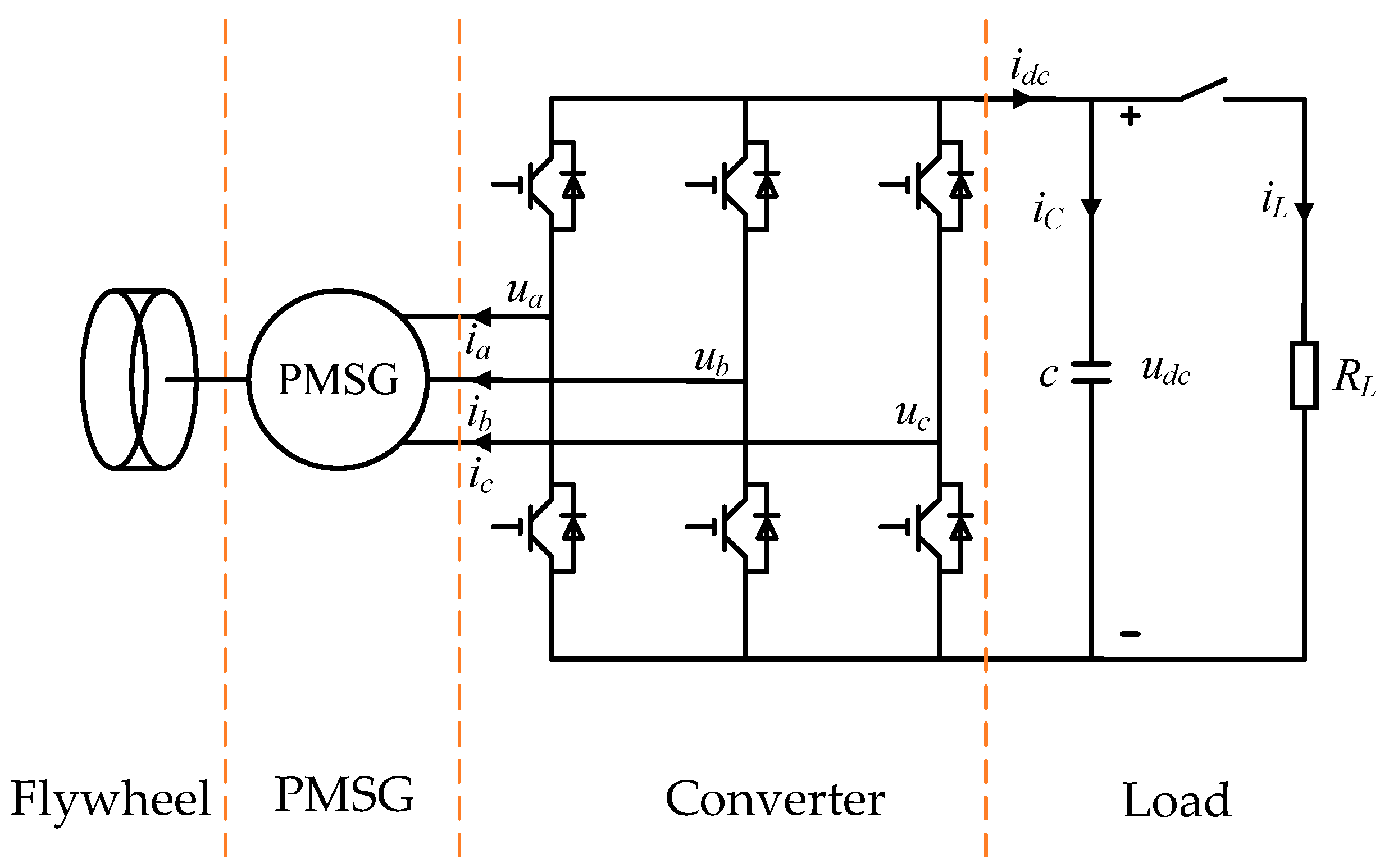
The flywheel energy storage system comprises a flywheel rotor, a permanent magnet synchronous motor (PMSG), a three-phase full-bridge pulse-width modulation (PWM) converter, and a DC-side capacitor (C). The main circuit topology is illustrated in Figure 1. In this configuration, , , and represent the three-phase voltage output from the AC side of the converter, while , , and denote the three-phase input currents of the permanent magnet synchronous motor. Additionally, , , , and correspond to the DC-side voltage of the converter, the output current on the DC side, the charging current of the capacitor, and the equivalent load current on the DC side, respectively. Using the relationship between the reference direction of voltage and stator current, the FESS equation is derived. A transformation is then applied to convert this equation into the first through fifth equations in the synchronous coordinate system (1), where the d-axis aligns with the ψf-axis, and the q-axis is orthogonal to the ψf-axis. The power balance between the PMSG and the directional converter is represented in the sixth equation of Equation (1), where the negative sign indicates the direction of the current as defined in Figure 1.
where , , , , , correspond to the d-axis and q-axis stator current, voltage, and inductance components, respectively. represents the stator resistance, while and are the electrical and mechanical angular velocities, respectively. is the permanent magnet flux linkage, and is the number of pole pairs. , , , and are the moment of inertia, mechanical damping coefficient, mechanical load torque, and electromagnetic torque, respectively. , , and indicate the voltage, current, and capacitance of the DC link, respectively. denotes the switching loss of the insulated gate bipolar transistor (IGBT) device, and is the load equivalent resistance. In this paper, the d-axis direction is chosen to align with the direction of the permanent magnet flux linkage, which effectively simplifies control and reduces instability in the control process.
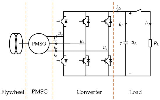
Figure 1.
Topology diagram of the main circuit of the FESS.
The fixed gain of the traditional Linear Active Disturbance Rejection Controller (LADRC) makes it challenging to simultaneously reduce overshoot and enhance the system’s disturbance immunity. To further investigate this issue, it is essential to first establish its mathematical model. The traditional LADRC typically employs a voltage–current double closed-loop control system, where the input of the voltage outer loop is and the output is . To derive the dynamic relationship between and , the first, second, and fifth equations in Equation (1) are substituted into the sixth equation, resulting in Equation (2):
Define the state variable, then Equation (2) can be converted into Equation (3):
The righthand side of Equation (3) is considered to be a perturbation except for , which is denoted as , with differentiating , , giving the derivative of to obtain Equation (4):
By defining , the third-order linear system (5) can be obtained:
where and are the bus voltage and its differential, respectively; is the newly expanded state variable in the Linearly Expanding State Observer (LESO). The physical interpretation of is the total perturbation sum of the system, encompassing both the changes in the internal dynamics and the external forces that are independent of the system and originate from the environment. This variable is denoted as ; ; .
Construct the expansion state observer LESO:
where , , and are the observed values of the state variables , , and , respectively; is the observation error; and is the gain coefficient corresponding to the linear feedback, with subscripts .
The disturbance compensation link is designed as:
where and are the controller parameters.
The disturbance compensation link is designed as:
According to the pole configuration method [24], the conventional LESO in Equation (4) is configured as follows:
is the controller bandwidth; w0 is the observer bandwidth; and is the damping ratio.
3. Traditional LADRC Maladaptive Analysis Is Section
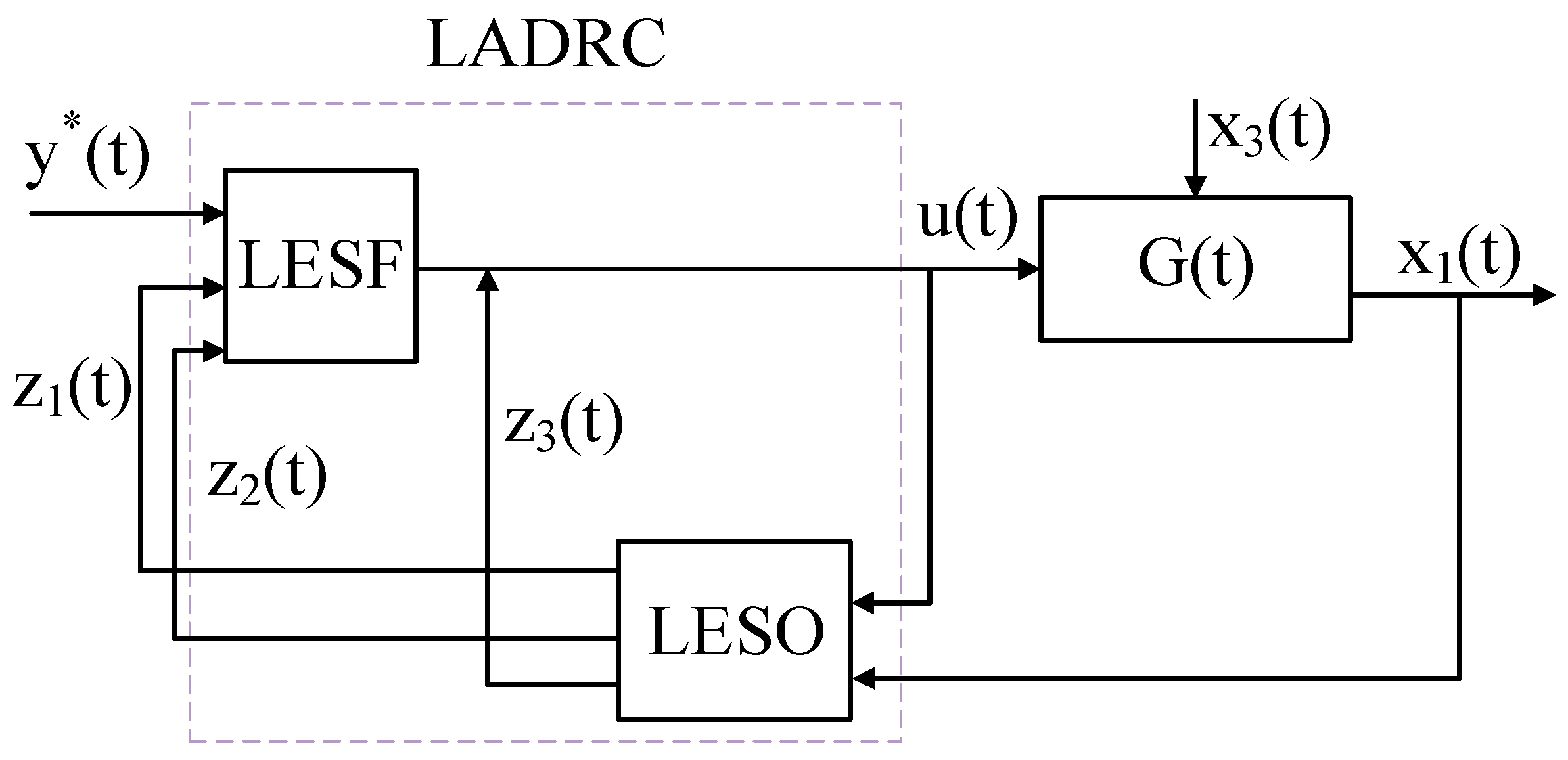
The advantage of linear self-immunity control lies in its ability to simplify parameter tuning, the design of the controller can be accomplished by merely determining the bandwidth. From Equations (9) and (10), it is evident that the bandwidth is fixed. However, a fixed bandwidth does not necessarily represent the optimal solution. In the system, an increase in observer bandwidth can enhance the system’s anti-jamming capability, but it may also lead to overshooting oscillations and other undesirable effects. To establish the relationship between observer bandwidth and control signal, this paper employs frequency domain analysis to examine how variations in observer bandwidth impact control performance. The LADRC-based system is illustrated in Figure 2. In this system, there are two external inputs: the reference signal and the disturbance , with one output, . Additionally, for the controller, the external inputs consist of and , while the output is the control signal . The first step is to construct the transfer function that relates these elements.
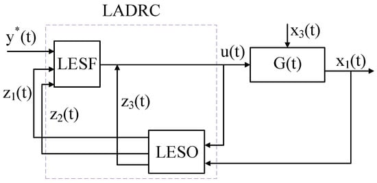
Figure 2.
LADRC-based system.
The error system between the original systems represented by Equations (5) and (6) is derived from Equation (11):
Converting it to the s-domain, it is expressed as Equation (12) and its solution is Equation (13):
Joining Equation (13) with Equation (8) results in Equation (14):
In addition, the relationship between the system state variable and the disturbance variable can be determined using Mason’s formula:
According to the superposition theorem, the following relationship can be derived from Equations (14) and (15):
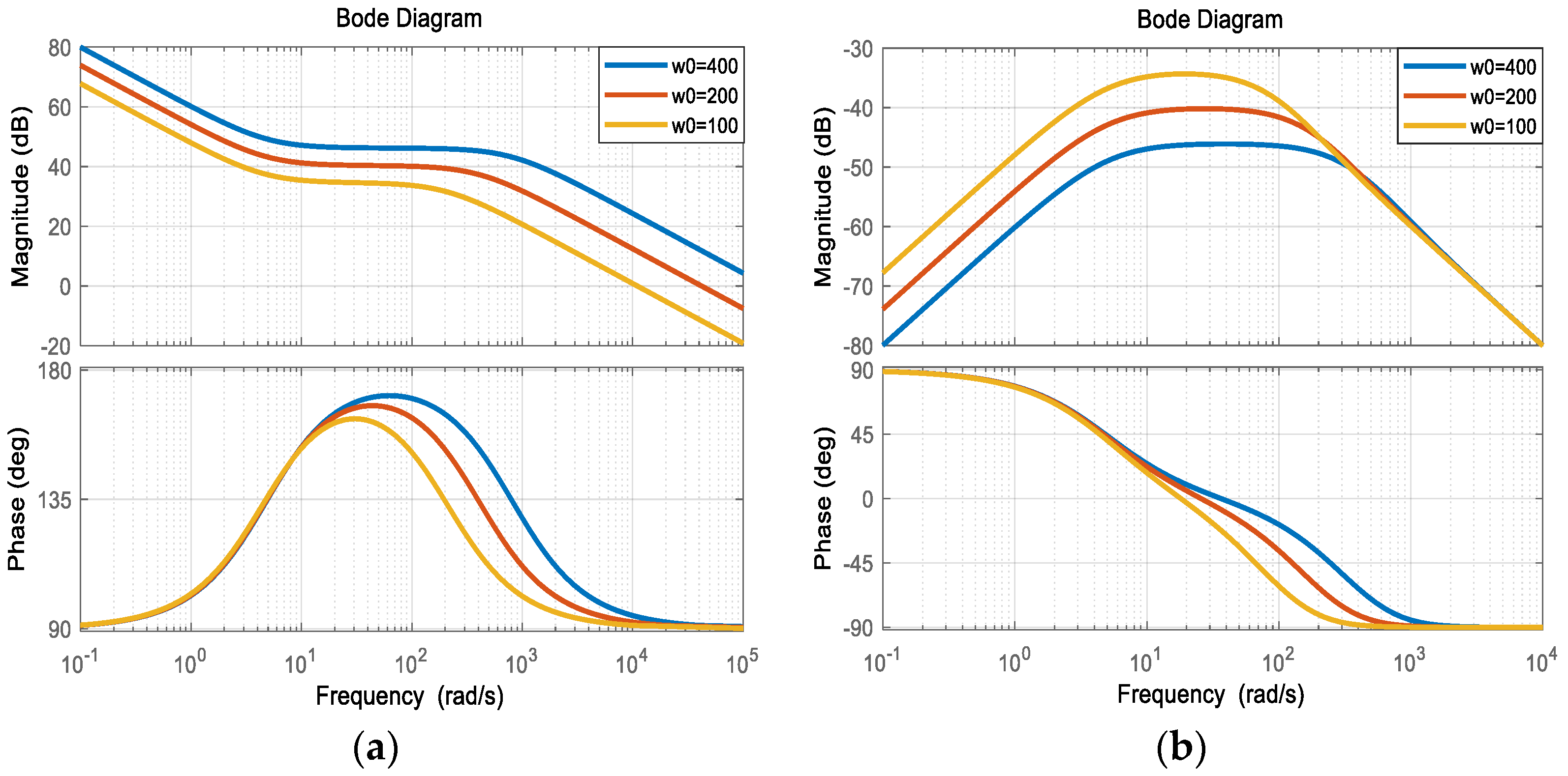
Figure 3 displays the Bode plots of Equations (16) and (17), where , , and takes the values of 400, 200, and 100, respectively.
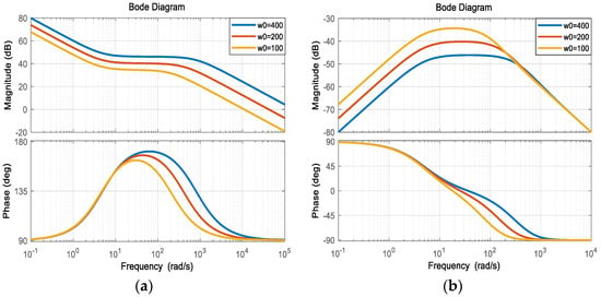
Figure 3.
(a) Bode diagram of the ratio of the output signal to the input signal , which mainly reflects the relationship between them; (b) Bode diagram of the ratio of the input signal to the perturbation signal , which mainly reflects the relationship between them.
From Figure 3, the following can be observed:
- The amplitude of the control signal increases with an increase in ;
- When is larger, the curve representing the system state in response to perturbation becomes flatter, indicating that the sensitivity of state to perturbation is reduced. This suggests that the system exhibits high anti-interference performance.
For LADRC-based systems, a fixed gain is not optimal for ensuring system robustness and control signal smoothing. In the precise regulation of the control system, when faced with significant external perturbations, a higher controller gain is indeed necessary to achieve a rapid response from the flywheel energy storage system and to quickly stabilize the DC bus voltage through discharge behavior. However, it is impractical to maintain a high gain setting when the intensity of perturbations is low, as this will cause the control signal to remain at a consistently high amplitude. While this may accelerate the dynamic response of the flywheel and aid in voltage stabilization, the inertial characteristics of the flywheel can complicate the management of its speed variations over time, thereby increasing the risk of overshooting.
In the event of overshooting, the controller attempts to compensate through a feedback mechanism. However, due to the inertia of the flywheel, this regulatory effect may be delayed. If the regulation process is repeated improperly, it can induce oscillatory behavior in the system and potentially lead to instability, threatening both system stability and control effectiveness. To mitigate these issues, the control strategy should avoid maintaining the control signal at a high amplitude for extended periods. Since the amplitude of the perturbation is not constant, it is essential to appropriately reduce the controller gain when the level of perturbation decreases. Such adaptive adjustments can effectively minimize the occurrence of overshooting without compromising control performance, thereby ensuring the stability and efficiency of the system.
4. Feasibility Analysis of DVGESO and Its Design
The core design of the discrete variable-gain expanded state observer (DVGESO) is centered around the implementation of an error-based dynamic gain mechanism. This mechanism enhances the flywheel energy storage system’s ability to reject both internal and external disturbances. By dynamically adjusting the observation gain during continuous system operation, the dynamic tracking performance is optimized without compromising steady-state accuracy. The design of DVGESO considers potential variations in system parameters and model uncertainty. By incorporating a variable gain mechanism, the observer can adapt to these fluctuations and ensure the accuracy of the estimation. This design enhances the robustness of the system, enabling it to sustain a stable performance despite uncertainties and non-ideal conditions in real-world applications.
4.1. DVGESO Design
In order to better adapt to the needs of digital control systems, the system must first be discretized. Equation (5) is expressed in its general form:
where x(t) is the state vector; u(t) is the control input; f(t) represents the external perturbation; and A, Bu, Bd are the system matrices. , , .
The discretization is performed using a zero-order hold (ZOH), which maintains the control input constant throughout the sampling period in practical digital control. By substituting ZOH into Equation (18), the discrete dynamic model of the PMSG is derived as follows:
where represents the discretized state transfer matrix of the system, denotes the input influence matrix, and signifies the product of the perturbations over the sampling period. , , , represents the sampling period, while denotes the output matrix, .
In this section, we propose a new discrete variable-gain extended state observer (DVGESO) to estimate unmeasurable system states and total perturbations. The DVGESO is designed as follows:
where, , . The gain matrix, denoted as , is dynamically adjusted based on the estimation error, . The parameters Lc, , , and represent the bandwidth parameters as referenced in [25]; . A nonlinear gain function is represented by , with , , , and as adjustable positive constants.
The estimation error is ; therefore, its dynamic equation is:
where .
When the DVGESO controller detects a disturbance in the system, it first calculates the error function as described in the equation . Next, it employs the equation to determine the variable gain function . Subsequently, the equation is utilized to derive the gain matrix , which is dynamically adjusted based on the estimation error. Finally, the observer is updated using the equation , allowing the observer gain to be dynamically modified in response to the error, thereby achieving adaptability.
4.2. DVGESO Stability Analysis
The stability analysis of DVGESO is conducted next, and the analytical procedure necessitates the use of two lemmas:
Lemma 1
([26]). Given the system , where is the state, is the external input, and is the mapping matrix. If and , one has .
Lemma 2
([27]). Let matrix and s(A) be the spectral radium of A. Then, for any , there exists an induced consistent norm such that .
DVGESO stability is analyzed in the following manner:
Calculation , where , , . Let , . The characteristic equation of can be derived:
where , The three types of eigenvalues are discussed next:
- 1.
- If all the eigenvalues are positive real numbers and , then we obtain and . Therefore . In order for the characteristic equation to hold, then ;
- 2.
- If all eigenvalues are negative real numbers and , it is first necessary to construct an auxiliary function , where ε is a positive constant. With images, it follows that when or , , for this case, holds if . Setting , then , so that holds when , and , so that . Since and , . Similar to (1), in order for the characteristic equation to hold, ;
- 3.
- If both positive and negative real eigenvalues exist, the discussion for positive real eigenvalues is the same as that under condition (1), and the discussion for negative real eigenvalues is the same as that under condition (2).
From the above discussion, it follows that , and hence the spectral radius of satisfies . By Lemma 2, there exists a positive constant and an induced paradigm such that:
is the perturbation maximum term of .
Since the initial estimation error is bounded, as stated in Lemma 1, it can be concluded that is convergent. Therefore, the designed observer DVGESO is stable.
5. Simulation and Experimental Analysis
In order to verify the effectiveness of the proposed control strategy and parameter selection method, a simulation study and analysis were conducted using MATLAB/Simulink. The parameters utilized in the simulation are presented in Table 1, and the voltage reference is set at 300 V.

Table 1.
Parameters of the main circuit of FESS.
The initial speed of the flywheel energy storage system is set at 12,000 r/min, and the perturbation involves a sudden increase in the DC side load from 300 Ω to 600 Ω. In a no-load condition, the initial voltage of the DC link is 300 V. The controller parameters are detailed in Table 2. To evaluate the effectiveness of the proposed control strategy in addressing the trade-off between steady-state error and overshoot, experiments are conducted and compared with traditional linear extended state observers that have varying parameter bandwidths, specifically the following—LESO1: , LESO2: , and LESO3: .

Table 2.
Controller parameters.
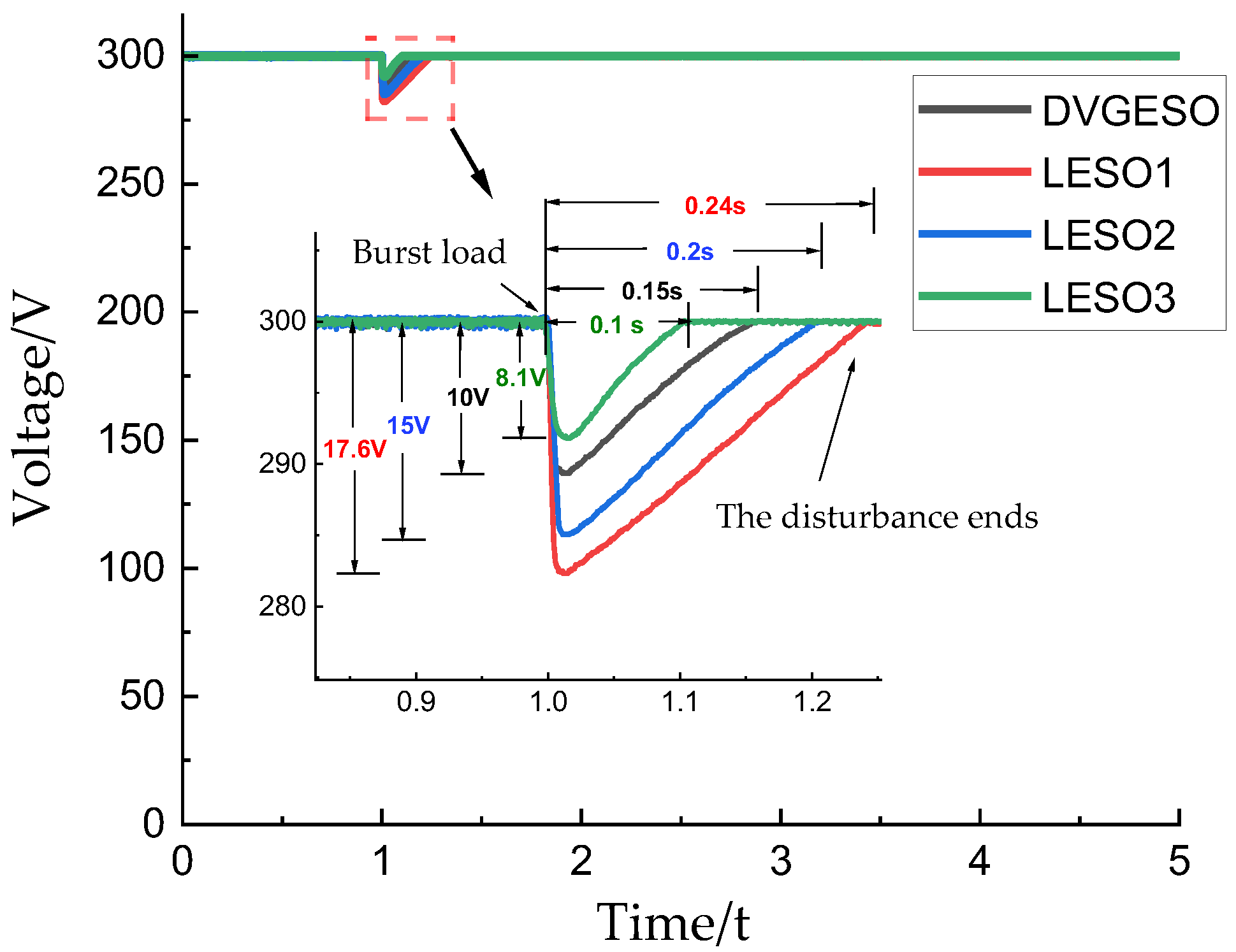
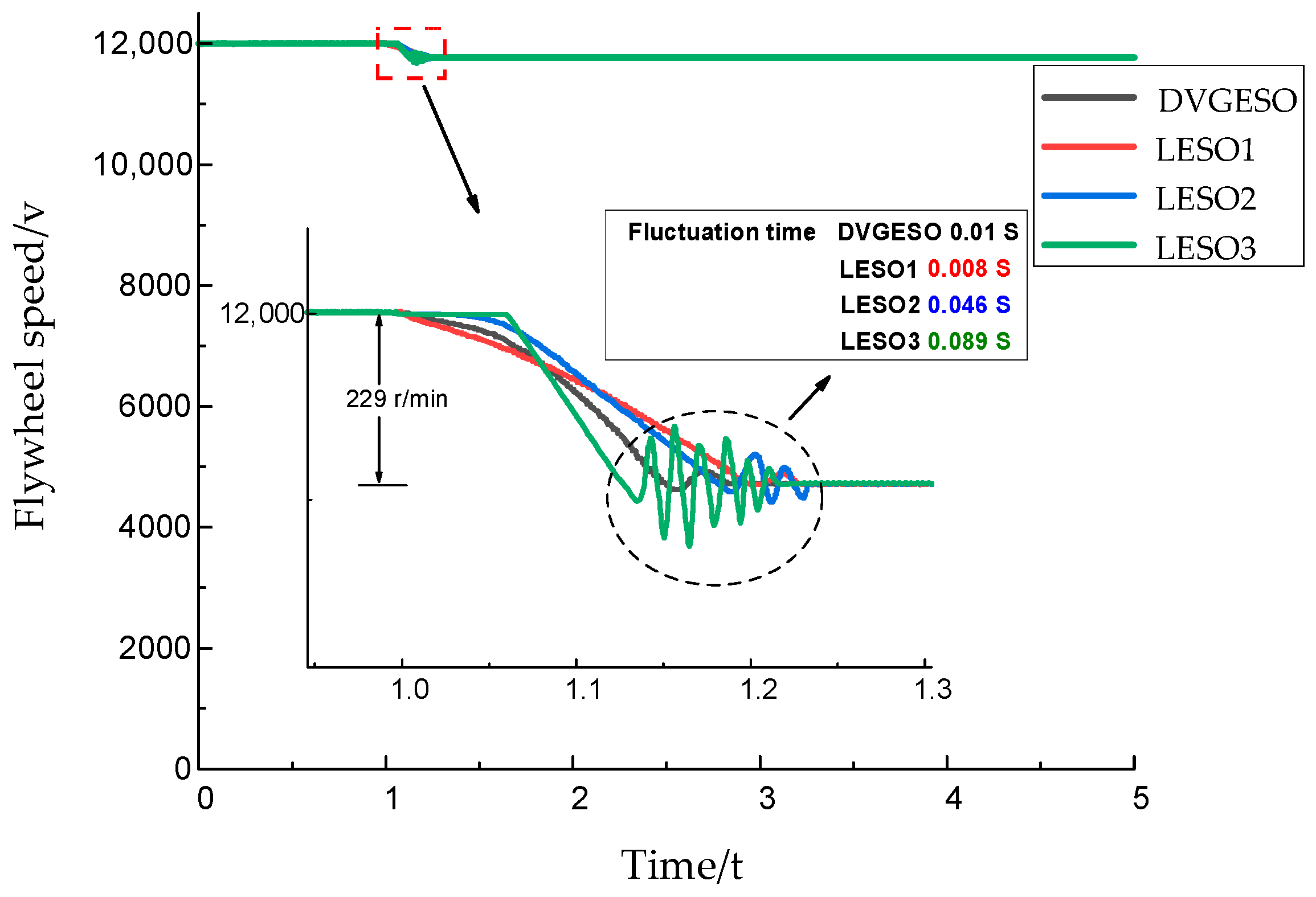
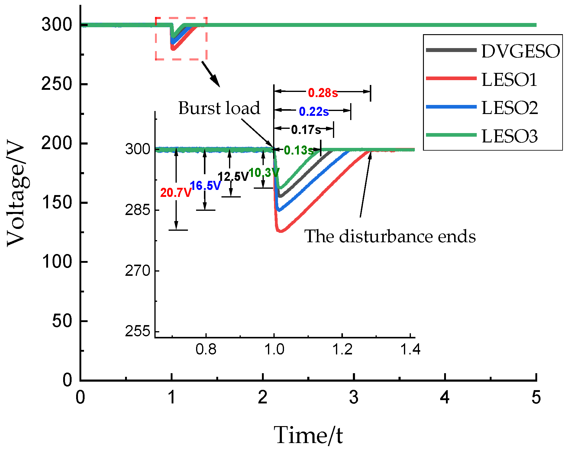
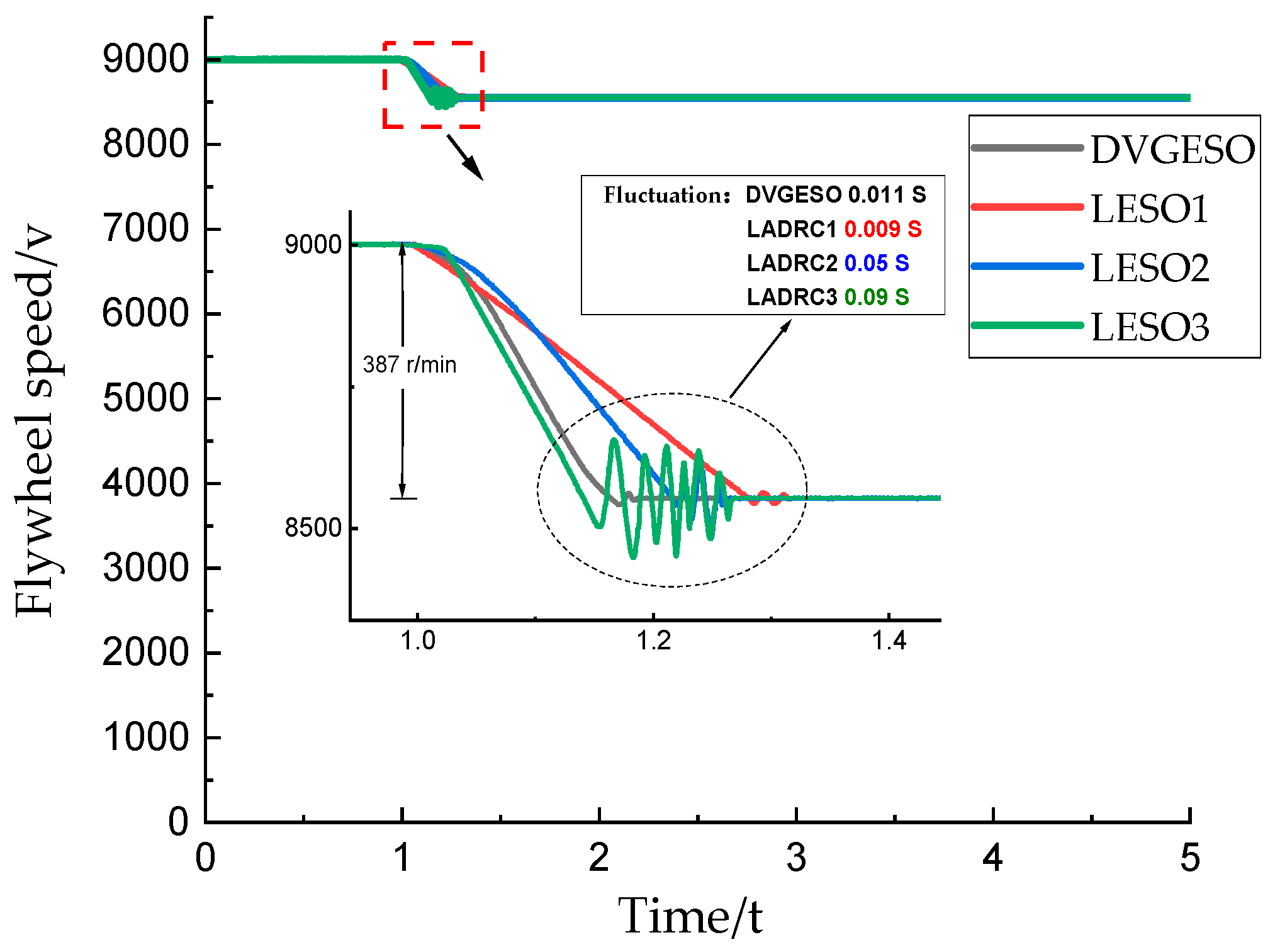
Figure 4 and Figure 5 and Figure 6 and Figure 7 illustrate the simulation results for voltage drop and flywheel oscillation at initial speeds of 12,000 r/min and 9000 r/min, respectively. Table 3 provides a summary of the detailed simulation results. Based on the findings of this study, the following conclusions can be drawn.
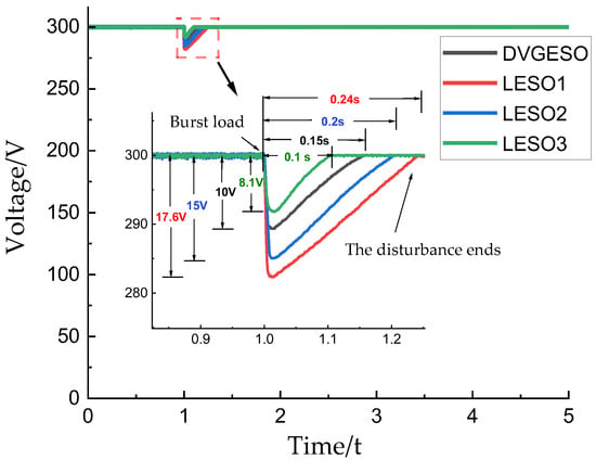
Figure 4.
Busbar voltage comparison chart (12,000 r/min).
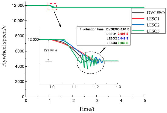
Figure 5.
Flywheel oscillation comparison chart (12,000 r/min).
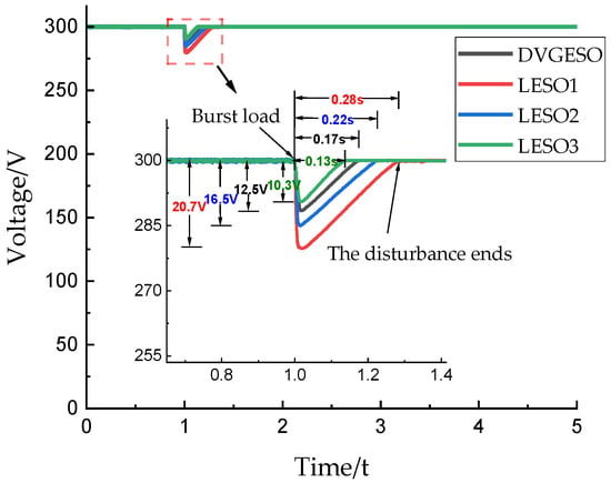
Figure 6.
Busbar voltage comparison chart (9000 r/min).
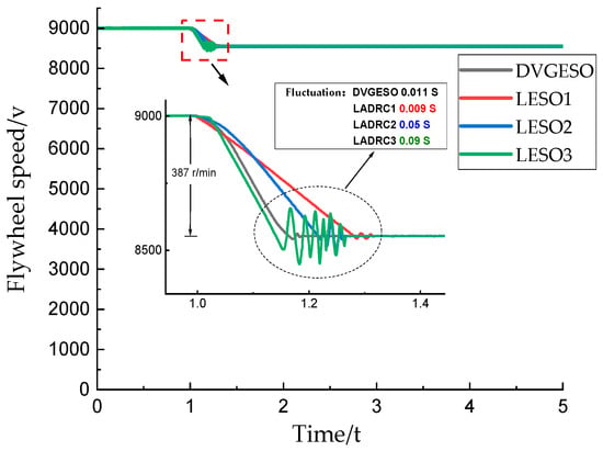
Figure 7.
Flywheel oscillation comparison chart (9000 r/min).

Table 3.
Specific experiment results.
- When the LESO-based system has a large observer bandwidth, its resistance to disturbances increases. As illustrated in Figure 4 and Figure 6, as well as in Table 3, it is evident that when a disturbance occurs, the state change of LESO1 is the most significant, followed by LESO2 and LESO3. In Figure 4, the voltage drop of LESO1 is 117% of that for LESO2 and 217% of that for LESO3. Additionally, the disturbance recovery time for LESO1 is 120% of that for LESO2 and 240% of that for LESO3, respectively. Similarly, in the experiment depicted in Figure 6, the voltage drop of LESO1 is 125% of that for LESO2 and 201% of that for LESO3, with recovery times of 127% and 215%, respectively. As the initial speed of the flywheel decreases, the energy stored in the flywheel energy storage system diminishes, resulting in a greater bus voltage drop at an initial speed of 9000 r/min for the same disturbance.
- The control signal u(t) generated by the LESO with a larger bandwidth increases in amplitude, thereby exacerbating the flywheel oscillation. From Figure 5 and Figure 7, as well as Table 3, it is evident that the peak value of u(t) of LESO3 is the highest, followed by LESO2 and LESO1. At 12,000 r/min, the maximum peak value of oscillations for LESO3 is 151% of that for LESO2 and 332% of that for LESO1, respectively. The minimum peak value is 193% of that for LESO2 and 297% of that for LESO1, respectively. The highest peak values of oscillations for LESO3 in Figure 7 are 162% for LESO2 and 282% for LESO1, while the lowest peaks are 213% and 270% for LESO1, respectively. Additionally, the decrease in rotational speed in Figure 7 is 169% of that in Figure 5, further confirming the impact of the reduction in the initial speed of the flywheel on its ability to resist interference.
- By adaptively adjusting the gain, the proposed DVGESO can prevent excessive oscillation of the flywheel caused by an increase in the control signal, while also ensuring the system’s ability to resist interference during disturbances. When the initial speed of the flywheel was 12,000 r/min, the voltage drop of DVGESO was 123%, 66.7%, and 56.8% of that observed in LESO3, LESO2, and LESO1, respectively. The disturbance recovery times were 130%, 77.3%, and 60.7%, respectively. The degree of flywheel oscillation reached 42.7%, 64.7%, and 142% of the highest peak, and 35.3%, 68.3%, and 105% of the lowest peak, respectively. The oscillation times were 11.2%, 21.7%, and 125%, respectively. The same results were observed at 9000 r/min, which are not repeated here.
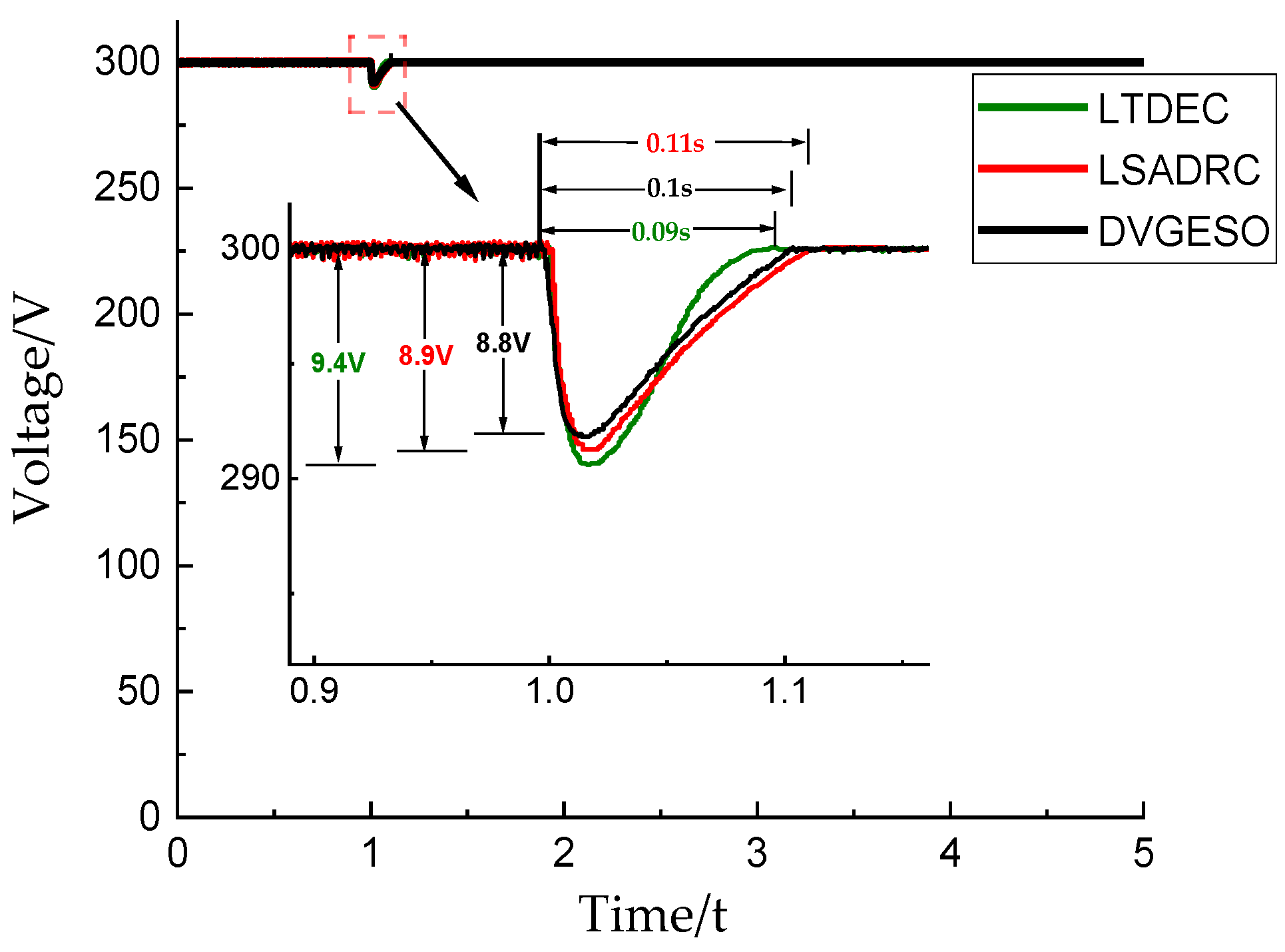
In order to further verify the effectiveness of the proposed control strategy, the flywheel speed is set to 12,000 r/min. The DVGESO is compared with the linear tracking differentiator-based energy controller presented in reference (LTDEC) [10] and the linear switching self-resistant controller discussed in reference (LSADRC) [21]. The comparison results are illustrated in Figure 8 and Figure 9.
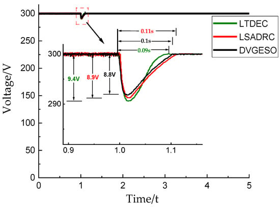
Figure 8.
A comparison plot of bus voltage at 12,000 r/min for various control strategies.
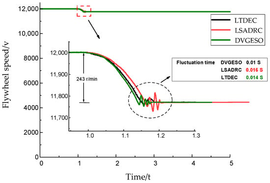
Figure 9.
Comparison of flywheel pendulum oscillations under different control strategies at 12,000 r/min.
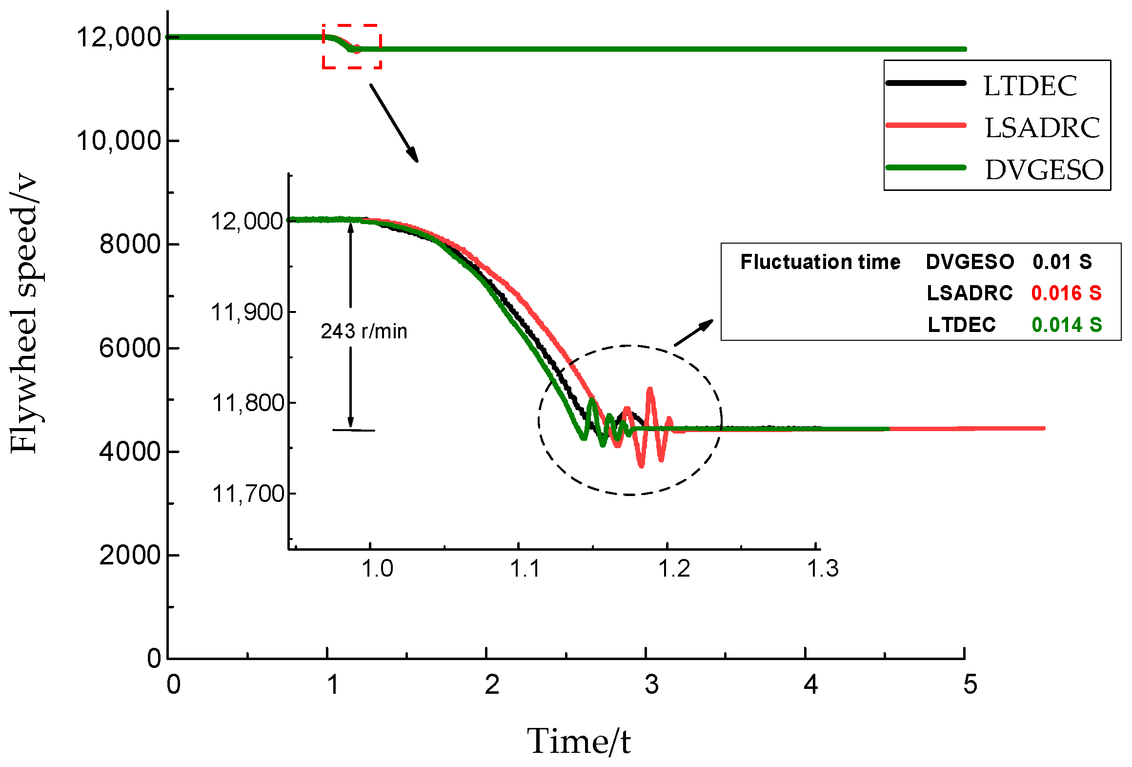
As illustrated in Figure 8 and Figure 9, after the system experiences a disturbance, DVGESO exhibits the lowest voltage drop of 8.8 V, while LTDEC demonstrates the fastest recovery speed of 0.09 s. However, the flywheel oscillation in LTDEC is more pronounced than that in DVGESO, with LTDEC oscillating for a duration of 0.014 s and an oscillation amplitude of 50 r/min. In contrast, LSADRC exhibits the most severe oscillation, with an amplitude of 86 r/min.
6. Conclusions
In order to address the trade-off between steady-state error and transient response, and due to the fixed gain in traditional linear active disturbance rejection control, this paper proposes a variable-gain discrete linear active disturbance rejection control method for flywheel energy storage systems. This approach enhances the system’s ability to suppress disturbances, such as load changes in DC bus voltage, and reduces the occurrence of overshoot compared to traditional control algorithms. The following conclusions are drawn from this study:
- Through theoretical analysis and mathematical modeling, this study quantitatively explores the influence of observer bandwidth on the interference suppression efficiency of the system, revealing the internal relationship between bandwidth and the amplitude of the control signal. It is found that increasing the observer’s bandwidth can enhance the system’s resistance to external disturbances; however, this also leads to an inevitable increase in the amplitude of the control signal. This phenomenon highlights the inherent challenges faced by traditional linear active disturbance rejection control in balancing system stability with anti-interference performance, underscoring its limitations in achieving optimal control performance.
- The structure of the DVGESO control model is presented in this study, and the implementation of the discrete design for the digital control system achieves real-time optimization of the controller parameters. By dynamically adjusting the gain function, the model overcomes the limitations of traditional fixed-gain controllers, enhancing the system’s anti-interference capability and robustness. This approach offers a new perspective for designing flywheel energy storage control systems.
- DVGESO enhances the robustness and stability of the system by dynamically adjusting the observer gain to effectively respond to variations in system parameters and internal perturbations. This improvement not only increases the efficiency and response speed of the flywheel energy storage system but also reduces energy loss caused by system deviations, which is crucial for enhancing energy utilization efficiency and lowering operational costs. Additionally, the real-time performance and adaptive capabilities of DVGESO minimize the need for manual intervention, further enhancing the system’s reliability. These advantages of DVGESO will yield significant economic and environmental benefits for flywheel energy storage systems when implemented in practice. Future studies will explore the performance of DVGESO under various operating conditions and its potential applications in optimizing energy storage and grid stability.
Author Contributions
Conceptualization, P.Y.; methodology, J.S.; software, P.Y.; validation, P.Y. and X.S.; formal analysis, P.Y.; investigation, P.Y.; resources, J.S.; data curation, P.Y.; writing—original draft preparation, P.Y.; writing—review and editing, P.Y.; visualization, J.S.; supervision, J.S.; project administration, X.S.; funding acquisition, J.S. All authors have read and agreed to the published version of the manuscript.
Funding
This work was supported by the National Natural Science Foundation of China, grant number 52077120.
Data Availability Statement
The data presented in this study are available on request from the corresponding author.
Conflicts of Interest
The authors declare no conflicts of interest.
References
- Benqian, D.; Pengyue, W.; Haibo, W.; Sen, S.; Fei, W.; Yantong, Z.; Haibo, P.; Jiandong, L.H.T. Primary frequency modulation technology of flywheel energy storage assisted thermal power plant. Therm. Power Gener. 2024, 53, 81–88. [Google Scholar] [CrossRef]
- Sheng, A.; Zhongrui, L.; Ziling, N. Charge and Discharge Control Strategy of Flywheel Energy Storage System Based on the Double Hysteresis Loop. Power Electron. 2023, 57, 57–59. [Google Scholar]
- Badrzadeh, B.; Cardozo, C.; Hishida, M.; Shah, S.; Huq, I.; Modi, N.; Morton, A. Grid-Forming Inverters: Project Demonstrations and Pilots. IEEE Power Energy Mag. 2024, 22, 66–77. [Google Scholar] [CrossRef]
- Hutchinson, A.J.; Gladwin, D.T. Flywheel Energy Storage for ancillary services: A novel design and simulation of a continuous frequency response service for energy limited assets. IEEE Open Access J. Power Energy 2024, 22, 434–445. [Google Scholar] [CrossRef]
- Xu, C.; Jinfeng, H.; Conglin, L. Improved high-order sliding mode active disturbance rejection control for bipolar DC microgrids. Power Syst. Prot. Control 2024, 52, 111–122. [Google Scholar] [CrossRef]
- Jing, L.; Zhao, H.; Su, S.; Wei, W. A Fuzzy Incremental Proportional Integral Derivative Control Strategy for Flywheel Energy Storage Machines in Autonomous Vehicles. IEEE Trans. Autom. Sci. Eng. 2024, 21, 2374–2386. [Google Scholar] [CrossRef]
- Phosung, R.; Areerak, K.; Areerak, K. Improvement in the Stability of DC Electrical Power Distribution Systems in More Electric Aircraft. IEEE Access 2024, 12, 100908–100920. [Google Scholar] [CrossRef]
- Chen, X.; Tian, R.; Xu, S.; Jiang, W.; Wang, Y.; Hashimoto, S. A Novel Voltage-Current Dual-Drop Control Method for Shipboard DC Micro-Grid With Energy Storage Systems. IEEE Access 2024, 12, 62912–62925. [Google Scholar] [CrossRef]
- Zhongrui, L.; Ziling, N.; Sheng, A.; Jie, X.; Meihe, C. An Optimized Charging Control Strategy for Flywheel Energy Storage System Based on Nonlinear Disturbance Observer. Trans. China Electr. Electron. Soc. 2023, 38, 1506–1518. [Google Scholar] [CrossRef]
- Chen, Y.; Zhang, X.; Li, S.; Yang, J. Capacitance Energy Control for FESSs: Tracking Performance Analysis and Robust Design Against Variations of Speed, Load, and Capacitance. IEEE Trans. Energy Convers. 2024, 39, 974–987. [Google Scholar] [CrossRef]
- Si, X.; Duan, J.; Fan, S. Design of an adaptive frequency control for flywheel energy storage system based on model predictive control to suppress frequency fluctuations in microgrids. Electr. Power Syst. Res. 2024, 235, 110900. [Google Scholar] [CrossRef]
- Le, W.; Chunxia, Z.; Ziyu, Z.; Fang, P. Charge and discharge control technology of flywheel energy storage system based on weak field control. Power Syst. Technol. 2024, 1–11. [Google Scholar] [CrossRef]
- Jingqing, H. From PID Technique to Active Disturbances Rejection Control Technique. Control Eng. China 2002, 9, 13–18. [Google Scholar]
- Mohapatra, S.P.; Dash, P.K.; Bisoi, R. A new approach to instantaneous power based control of DFIG using active disturbance rejection control. e-Prime Adv. Electr. Eng. Electron. Energy 2024, 9, 100740. [Google Scholar] [CrossRef]
- Tian, P.; Le, Y.; Zhao, F.; Tian, K. Active Compensation Method for Magnetic Interference in Magnetically Shielded Room Based on Improved Linear Extended State Observer. IEEE Trans. Instrum. Meas. 2024, 73, 4009208. [Google Scholar] [CrossRef]
- Ur Rahman, A.; Campagna, N.; Pellitteri, F.; Oscar Di Tommaso, A.; Miceli, R. Stability-Centric Design of a Droop-Mounted Adaptive Nonlinear Control for EV Charging in DC Microgrid. IEEE Access 2024, 12, 123362–123375. [Google Scholar] [CrossRef]
- Haoran, X.; Chunfu, H.; Meng, L.; Xiao, L.; Shoudao, H. Research on Speed Control Strategy for Permanent Magnet Linear Synchronous Motor Based on Cascaded Linear-nonlinear Active Disturbance Rejection Controller. Proc. CSEE 2024, 44, 6158–6169. [Google Scholar] [CrossRef]
- Lin, P.; Zhang, S.; Wu, Z.; Li, J.; Sun, X.-M. A Linear–Nonlinear Switching Active Disturbance Rejection Voltage Controller of PMSG. IEEE Trans. Transp. Electrif. 2022, 8, 3367–3378. [Google Scholar] [CrossRef]
- Zhou, X.; Guo, S.; Ma, Y.; Li, Y.; Ma, C. DC bus voltage fluctuation suppression strategy of a converter system based on improved active disturbance rejection. Power Syst. Prot. Control 2023, 51, 68–78. [Google Scholar] [CrossRef]
- Zhang, X.; Yang, J. A DC-Link Voltage Fast Control Strategy for High-Speed PMSM/G in Flywheel Energy Storage System. IEEE Trans. Ind. Appl. 2018, 54, 1671–1679. [Google Scholar] [CrossRef]
- Wang, R.; Wu, Z.; Lin, P.; Sun, X.-M. Speed and Voltage Controllers Design for the Permanent Magnet Starter/Generator. IEEE Trans. Ind. Electron. 2023, 70, 8314–8323. [Google Scholar] [CrossRef]
- Pulikonda, M.; Kokil, P. Stability of Interfered Discrete-Time System with Concatenations of Quantization and Overflow. Circuits Syst. Signal Process 2023, 43, 302–317. [Google Scholar] [CrossRef]
- Meng, H.; Zhang, J.; Li, S. Design and analysis of event-triggered predictive sliding mode control for discrete-time constrained system. Int. J. Robust. Nonlinear Control 2023, 34, 1358–1369. [Google Scholar] [CrossRef]
- Gao, Z. Scaling and bandwidth-parameterization based controller tuning. In Proceedings of the 2003 American Control Conference, Denver, CO, USA, 4–6 June 2003, ISSN 0743-1619. [Google Scholar] [CrossRef]
- Li, S.; Zhang, J.; Gu, S. Discrete Time Trajectory Tracking Control for Four-Mecanum-Wheeled Mobile Vehicle: An Variable Gain ADRC Method. IEEE Rob. Autom. Lett. 2024, 9, 7771–7778. [Google Scholar] [CrossRef]
- Zhu, J.; Liu, J. A simple and scalable particle swarm optimization structure based on linear system theory. Memet. Comput. 2024, 16, 219–231. [Google Scholar] [CrossRef]
- Schmidt, J.W. Iterative Solution of Nonlinear Equations in Several Variables; Society for Industrial and Applied Mathematics: Philadelphia, PA, USA, 2000. [Google Scholar] [CrossRef]
Disclaimer/Publisher’s Note: The statements, opinions and data contained in all publications are solely those of the individual author(s) and contributor(s) and not of MDPI and/or the editor(s). MDPI and/or the editor(s) disclaim responsibility for any injury to people or property resulting from any ideas, methods, instructions or products referred to in the content. |
© 2024 by the authors. Licensee MDPI, Basel, Switzerland. This article is an open access article distributed under the terms and conditions of the Creative Commons Attribution (CC BY) license (https://creativecommons.org/licenses/by/4.0/).

