Article

Quantitative Risk Assessment of Steam Reforming Process by Hydrogen Generator, Using PHAST Model

by
Jongseok Lee
,
Hyunjun Kwak
and
Seungho Jung
*
Department of Environmental and Safety Engineering, Ajou University, Suwon 16499, Republic of Korea
*
Author to whom correspondence should be addressed.
Energies 2024, 17(22), 5704; https://doi.org/10.3390/en17225704
Submission received: 11 September 2024 / Revised: 7 November 2024 / Accepted: 12 November 2024 / Published: 14 November 2024
(This article belongs to the Special Issue Safety of Hydrogen Energy: Technologies and Applications)

Abstract

:
This study applied a risk assessment technique to the steam reforming process in hydrogen production facilities to generate baseline data for preparing safety protocols in related workplaces. To this end, consequence analysis (CA) was conducted using DNV-PHAST v.8.9., focusing on the reforming process, which operates at the highest temperature and pressure among related processes. This study predicted jet fire damage resulting from the total failure of a 65 mm syngas pipe at the rear end of the reformer, with a projected flame length of up to 23.6 m based on a radiant heat of 5 kW/m2. As per the assessment, a vapor cloud explosion (VCE) caused damage of up to 42.6 m at an overpressure of 0.07 bar (1 psi), while a flash fire had an impact range of approximately 12.7 m based on hydrogen’s LFL (lower flammable limit). This quantitative risk assessment of the general steam reforming process provides valuable basic data for the design and operation of related facilities.

1. Introduction

In the current global push toward carbon neutrality by 2050, many major countries and companies are committing to the ‘RE100’ (Renewable Electricity 100) global campaign promoting the use of electricity obtained from 100% renewable energy sources [1]. Among the new and renewable energy sources, hydrogen is gaining attention due to its ability to transfer a significant amount of stored energy without carbon emissions during the transition from fuel to electricity and vice versa [2]. The Hydrogen Council, where nearly 100 CEOs of global companies gather to share and promote a long-term vision for the hydrogen economy, predicts an annual hydrogen consumption of 540 million tons by 2050. This is approximately six times the current hydrogen usage and will represent a substantial 18% of global energy consumption by 2050. Bloomberg NEF predicts that the share of hydrogen energy will reach 22% by 2050 [3]. While hydrogen is currently used primarily as an additive and raw material in oil refining and industrial processes, its use as an energy source is expected to increase rapidly in the future. According to Korea’s ‘Hydrogen Industry Roadmap’, domestic demand for hydrogen is projected to reach 17 million tons by 2050, accounting for approximately 21% of total energy consumption [4].
The frequency of hydrogen accidents is increasing alongside rising hydrogen demand. According to the Ministry of Employment and Labor, a total of 23 accidents involving hydrogen-related fires, explosions, and leaks occurred over the 12 years from 2011 to 2022, resulting in 4 fatalities and 11 injuries. Notably, the number of such accidents has been increasing since 2017 [5].
Hydrogen, which is currently produced in large quantities around the world, is generated through a method called steam reforming. When methane (CH4), the main component of natural gas, reacts with pure water (H2O) at a temperature of 700 °C or higher, hydrogen (H2) and carbon monoxide (CO) are produced. The carbon monoxide is then reacted with water to generate additional hydrogen and carbon dioxide (CO2) as a by-product. Hydrogen can also be produced through a ‘by-product hydrogen’ method in which a gas mixture incidentally generated during petrochemical or steelmaking processes is simply purified to isolate hydrogen. Currently, most of the hydrogen produced in Korea is by-product hydrogen. Although Korea produces approximately 2 million tons of by-product hydrogen annually; most of it is internally reused in petrochemical and steelmaking processes, and only about 50,000 tons are distributed externally. As of the end of 2020, hydrogen produced worldwide was 78% reformed hydrogen and 18% by-product hydrogen [6]. Therefore, it is crucial to identify risk factors in the reforming process, evaluate the frequency of accidents, and predict accident damage.
Previous studies have addressed similar concerns. For instance, Kwak and Jong-Beom [7] verified the validity of site conditions by conducting a quantitative risk assessment on hydrogen charging stations in urban areas based on the Land-Use Planning (LUP) of the UNECE (United Nations Economic Commission for Europe). Gye and Hye-Ri [8] and others conducted a quantitative risk assessment (QRA) for high-pressure hydrogen charging stations in urban areas with a large population and high congestion between devices and equipment. Their study identified leakage and explosion of tube trailers and dispensers as the main risk factors, and additional mitigation devices such as compressors and firewalls for dispensers were suggested as alternatives for the safety of charging station operators, customers, and surrounding populations. Park and Byung-Jik [9] adopted a combination of LOPA (Layer of Protection Analysis) and RISKCURVES to conduct a risk assessment of hydrogen charging stations in urban areas. This method can potentially be applied not only to hydrogen charging stations but also for risk assessment and risk reduction for other highly flammable and explosive substances because it can shorten working time compared to existing risk assessments through CFD (Computation Fluid Dynamics) analysis. Kwak and Hyun-Jun [10] recommended applying a dual shutoff valve system in urban hydrogen refueling stations (HRSs) to safely limit the risk below the As Low As Reasonably Practicable (ALARP) criteria. Jeon and Bo-Il [11] assessed the quantitative risk of a hydrogen refueling station (HRS) in Cheonan City, South Korea, using process hazard analysis (PHA) software and a hydrogen risk assessment model. The study focused on evaluating the societal risk associated with potential accidents, specifically jet fire and overpressure events resulting from hydrogen leaks. The quantitative risk assessment revealed that the risks from jet fires and overpressures at the HRS are relatively low, falling below the ALARP level. Kim and Eun-Jung [12] simulated hydrogen leaks and explosions at hydrogen fueling stations in Korea. The study used computational fluid dynamics (CFD) software, FLACS, to model various scenarios involving leaks from pressurized hydrogen tanks. The simulations considered different pressures and leak hole sizes, validating the results against experimental data. The findings show that the location and size of the hydrogen leak significantly affect the spatial distribution of the explosion. The study also evaluates the effectiveness of a protective wall in mitigating the impact of explosions.
As a result of previous studies, research has been conducted to establish safety standards at hydrogen charging stations and hydrogen tube trailer supply facilities. While significant progress has been made in improving hydrogen production efficiency through catalyst design [13] and purification technologies [14], there remains a critical gap in the exploration of safety hazards associated with hydrogen production processes—particularly those utilizing the steam reforming method. Existing research has neglected a comprehensive analysis of major risk factors and the potential damage effects related to these facilities. As the number of hydrogen production facilities increases globally, understanding the risks of leaks, fires, and explosions in these environments is paramount for improving workplace safety.
This study aims to bridge this gap by performing a quantitative risk assessment of the hydrogen production process using steam reforming. Unlike previous studies, our research focuses on identifying the most hazardous points within the process and evaluating the impact range of potential accidents, thereby providing essential data for developing effective safety measures in related work environments. The paper will begin with a detailed introduction to the steam methane reforming (SMR) process, followed by a comprehensive risk assessment methodology. In subsequent sections, we will present the identification of hazardous points and analyze the calculated impact ranges of fires and explosions resulting from material leaks using the PHAST program. The relevance of our findings will be discussed in the context of enhancing safety protocols for hydrogen production facilities.

2. Methodology

2.1. Process Description

The subject of this study is hydrogen production by steam reforming natural gas. In this process, methane (CH4) gas, the main component of natural gas, reacts with pure water (H2O) at temperatures above 700 °C to produce hydrogen (H2) and carbon monoxide (CO). The carbon monoxide then reacts with water to produce additional hydrogen and carbon dioxide (CO2) by-product. Afterwards, the hydrogen concentration is increased through condensate separation and Pressure Swing Adsorber (PSA) processes. This study used data based on the case of company A, which produces hydrogen through steam methane reforming [15], to identify potential risks in the reforming process operated under the highest temperature and pressure conditions of the entire process. Details of each process step are summarized in Figure 1 and Table 1.

2.2. Selection of Accident Scenarios

This study applied a risk assessment centering on the reforming process, which operates at the highest temperature and pressure among the processes. In this plant, the 65 mm pipe at the rear of the reformer is a pipe connected by a flange, and it is the most dangerous pipe in the field due to high temperature and high pressure. For the accident scenario, fire and explosion damage were predicted considering the process conditions. For this, the accident damage prediction program, PHAST (Version 8.9), was used. It was developed by Det Norske Veritas (DNV) to analyze accident damage in chemical plants [16]. Accident scenarios were selected for unit facilities that handle chemicals, calculated considering both the worst-case and alternative accident scenarios. The method required to implement risk assessment for the process was referenced from the “Technical Guidelines on Consequence Analysis (CA) Techniques” of the Korea Occupational Safety & Health Agency [17]. Also, the leakage size of the pipe was based on the “Technical Guidelines on Leaking source modeling” of the same agency [18]. Table 2 presents three types of leak sizes and the worst and alternative scenarios.
Syngas, which was selected as the target material for the accident damage prediction, contains about 48 mol-% of hydrogen as a mixture, and the remaining 52% includes moisture (H2O), carbon dioxide (CO2), carbon monoxide (CO), and methane (CH4). Since hydrogen is the primary component of syngas, the substance was analyzed according to the behavior of hydrogen to obtain more conservative results for the impact range.
The weather conditions of the worst-case scenario were selected based on the “Technical Guideline for the Selection of Worst and Alternative Accident Scenarios” of the Korea Occupational Safety & Health Agency [19]. For the alternative-case scenario, the air temperature, ground temperature, and relative humidity were based on the average of the recent one-year (October 2022–October 2023) records in Pyeongtaek city, where the facility is located. Table 3 presents the weather conditions of the worst and alternative scenarios.
Complete fracture of the 65 mm diameter syngas pipeline, large leak, and medium leak cases were studied considering jet fire, vapor cloud explosion (VCE), and flash fire scenarios for 10 min leakage periods. The input data conditions for PHAST simulation are shown in Table 4.

3. Results and Discussion

3.1. Scenario and Damage Prediction Results

The damage prediction results for the scenario input conditions are shown in Table 5 below.

3.2. Results for Jet Fire

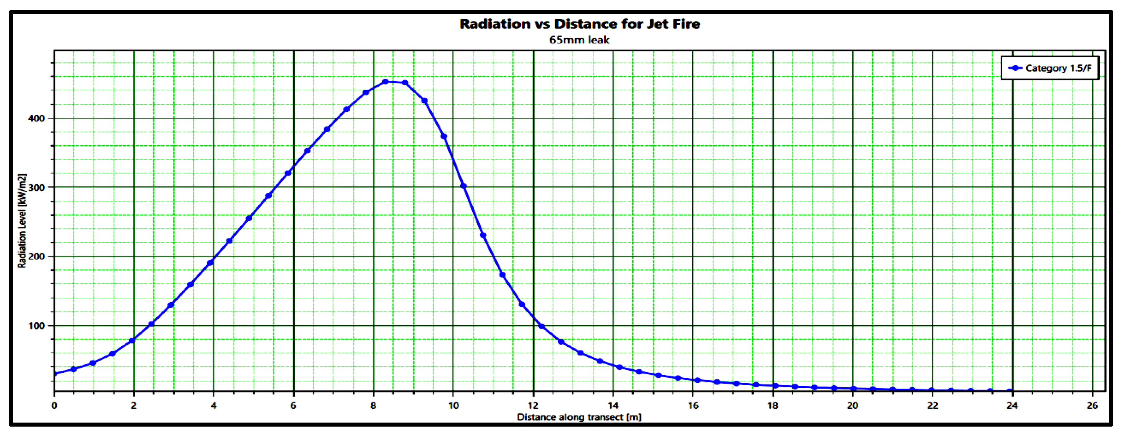
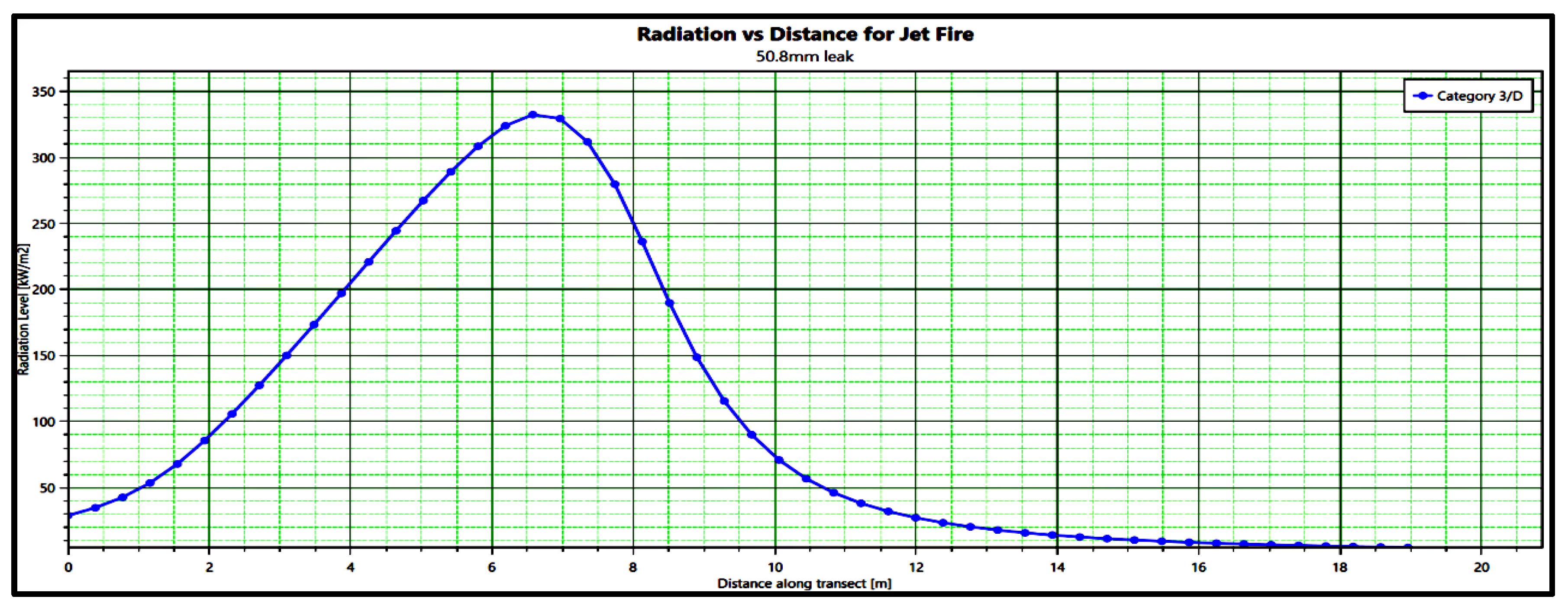
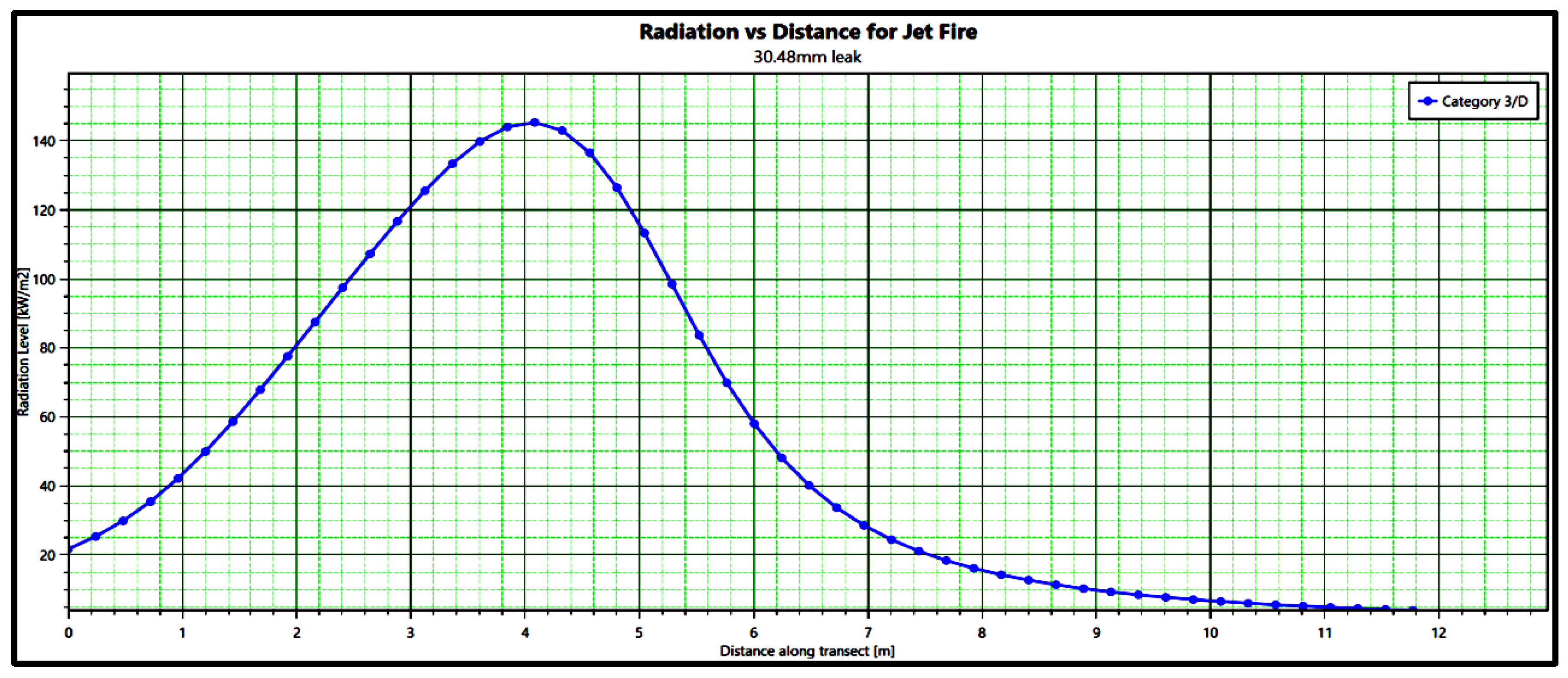
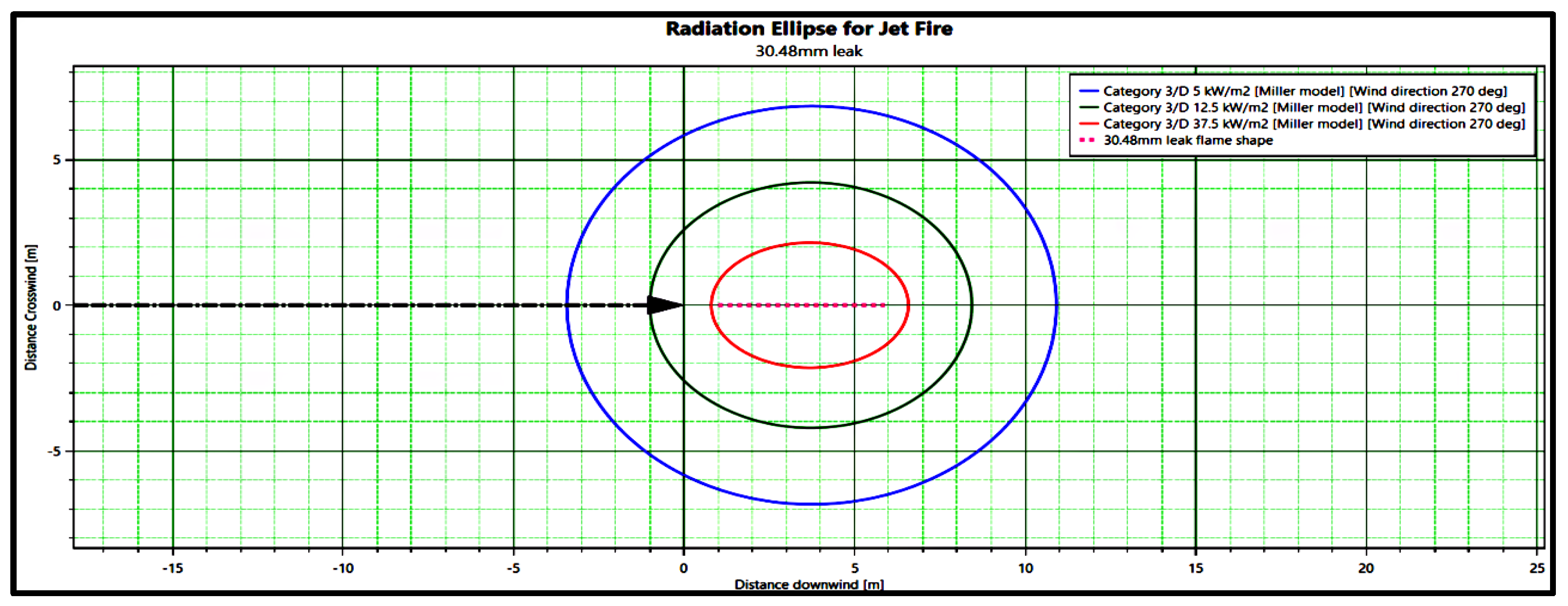
The Derek Miller Jet Fire Model was applied for jet fire analysis in this study. Table 6 shows the range of radiant heat effects of jet fire by leakage scenario. Figure 2, Figure 3 and Figure 4 illustrate the radiant heat value for each location from the source to the endpoint of the jet fire, while Figure 5, Figure 6 and Figure 7 depict the impact range by radiant heat for the jet fire. The flame length and radiant heat impact range are proportional to the size of jet fire leak hole.
In the case of a jet fire, it takes only a few seconds for a fire to occur. Therefore, it is necessary to select an evacuation route that allows workers within 24 m to evacuate based on radiant heat of 5 kW/m2.

3.3. Results for Vapor Cloud Explosion (VCE)

Examples of hydrogen-related vapor cloud explosions include the accident at the Muskingum River Power Plant in Ohio, USA, in 2007, and the accident at the Silver Eagle Refinery in Woods Cross, UT, USA, in 2009.
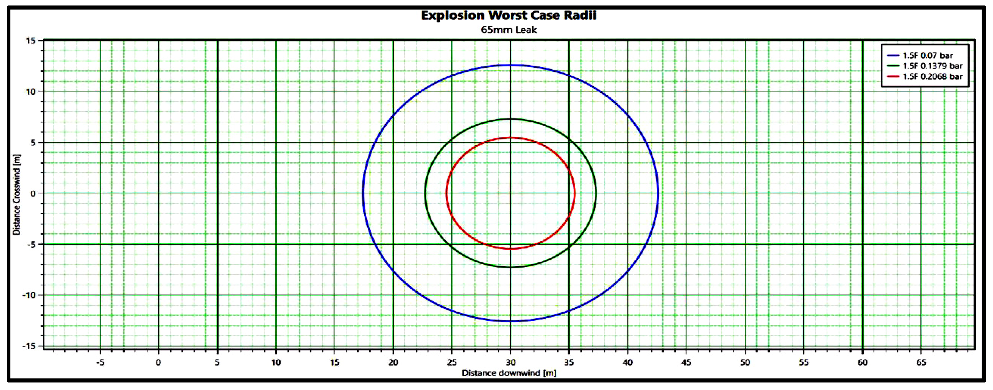
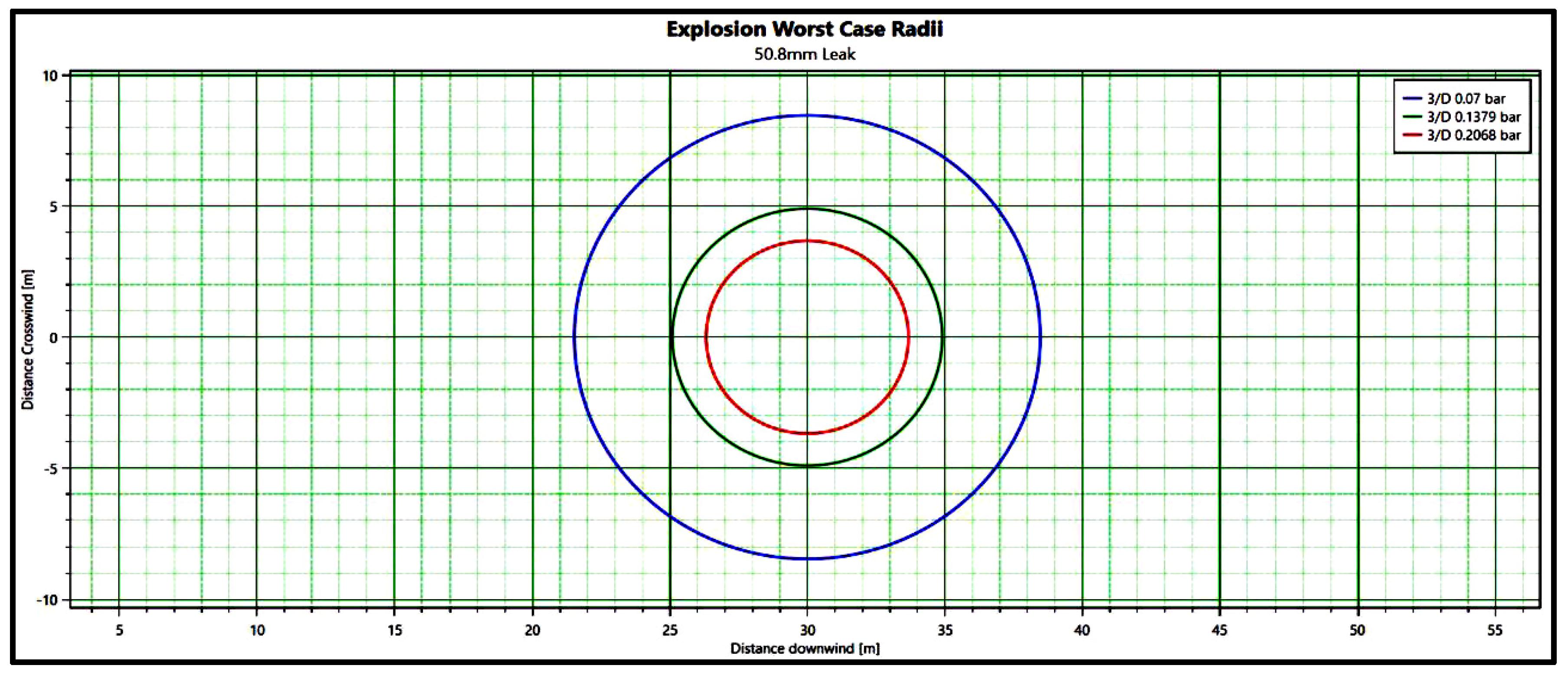
Table 7 and Figure 8, Figure 9 and Figure 10 show the overpressure impact distance according to the vapor cloud explosion by scenario. When a vapor cloud explosion occurs due to pipeline total failure at a 65 mm leak hole, it exhibits an impact range of 42.6 m at an overpressure of 0.07 bar (1 psi), and up to 35.5 m at an overpressure of 0.207 bar (3 psi). The smaller the leak hole, the smaller the range of vapor cloud formed, indicating a tendency to decrease the range of impact of the overpressure due to the explosion.

3.4. Results for Flash Fire

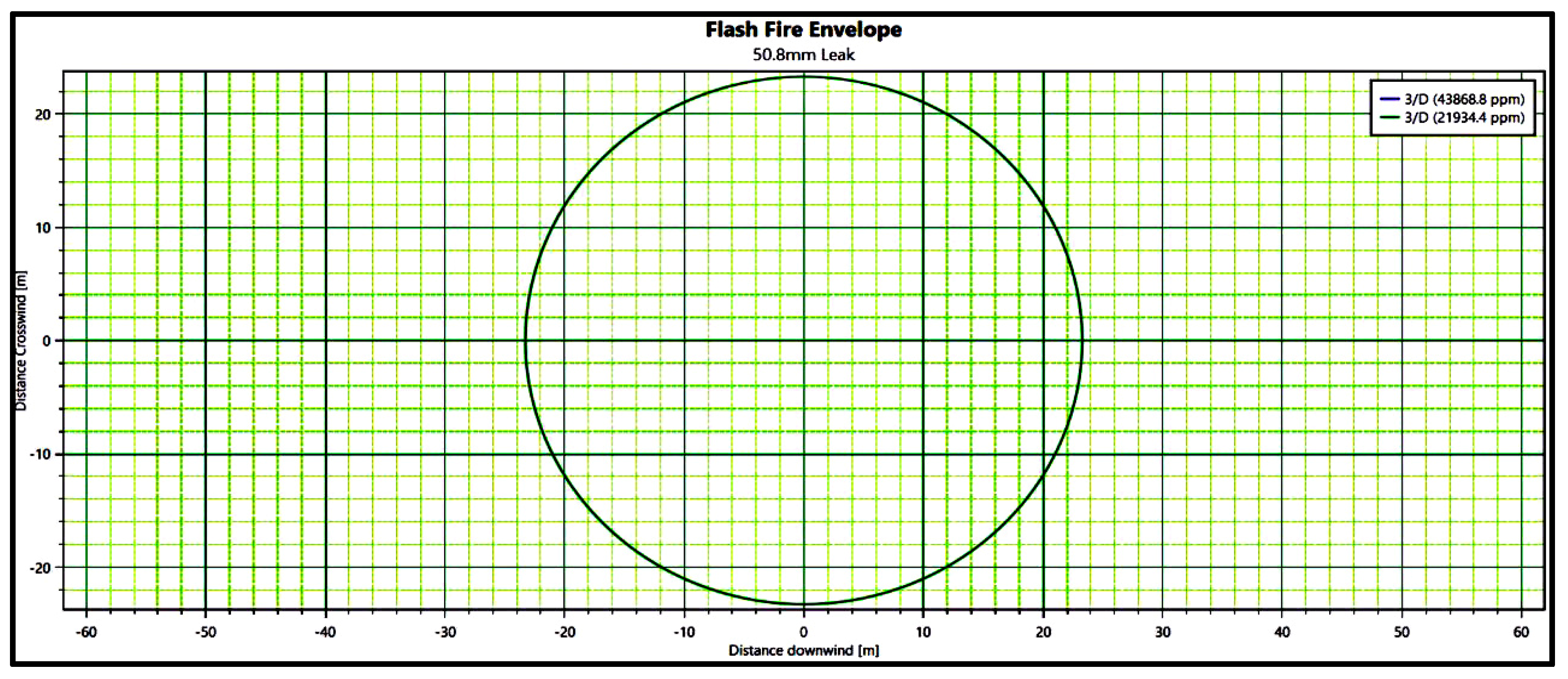
Table 8 and Figure 11 and Figure 12 show the impact distance according to the occurrence of a flash fire. For a flash fire occasioned by a 65 mm pipeline total failure, the impact range for the 4% concentration, which is the lower flammable limit (LFL) of hydrogen, was 12.7 m. In contrast, for 50.8 mm large leak and 30.48 mm medium leak scenarios, there was no flash fire at the LFL. Essentially, the larger the leak hole, the greater the impact range of the resultant flash fire.

3.5. Discussion

The analysis confirmed that larger leak holes result in greater impact ranges for jet fire, VCE, and flash fire scenarios. For jet fires, the flame length and radiant heat impact range are proportional to the size of the leak hole. Given that jet fires can occur within seconds of a leak, it is crucial to establish evacuation routes that allow workers within 24 m to evacuate quickly, based on a radiant heat threshold of 5 kW/m2. In case of VCEs, smaller leak holes result in smaller vapor cloud formations, which tend to decrease the overpressure impact range. For flash fires, larger leak holes lead to greater impact ranges. A quantitative risk assessment was conducted using PHAST v.8.9, a widely accepted and validated software for process safety analysis in the chemical process industries. Research on the sensitivity analysis and validation of the PHAST model for toxic or flammable materials supports its suitability [20,21]. This study further supports the model’s suitability through its extensive use in evaluating the consequences of leaks, fires, and explosions in similar high-temperature and high-pressure processes. The input data, detailed in Section 2.2, were carefully selected based on site conditions and guidelines [19]. Since there is no material information for syngas in the PHAST program, simulation was conducted by composing an approximate ratio of the composition. Most of the syngas composition is hydrogen, and the analysis was conducted according to the hydrogen’s behavior, resulting in more conservative results. This study is able to be used as data in related facilities as a quantitative risk assessment for a general steam reforming process.

4. Conclusions

This study applied CA to the steam reforming process of a hydrogen-generating facility to provide basic data for establishing safety measures at related workplaces. PHAST Professional version 8.9, developed by Det Norske Veritas (DNV), was used for the accident consequence damage analysis. The study focused on syngas, a substance flowing through the 65 mm mixed-gas pipe leak at the rear end of the reformer. Since hydrogen is the primary component of syngas, the substance was analyzed based on the behavior of hydrogen to obtain more conservative results for impact range. The accident damage prediction analysis for syngas, a flammable material, indicated that the primary risks to the plant are fires and explosions. While the worst-case scenarios have a relatively low frequency of occurrence compared to other scenarios, their potential for damage is significantly greater. It is necessary to prepare for such scenarios, as they can recur during long-term plant operation. It is also important to prevent large-scale accidents such as fires/explosions caused by flammable material leaks. Further, it is imperative to devise and work on ways to minimize damage in the event of an accident.
Focusing on the reforming process, which is operated at the highest temperature and pressure, accident damage predictions were conducted for jet fire, vapor cloud explosion (VCE), and flash fire scenarios involving a 65 mm syngas pipe at the rear end of the reformer. During total failure of 65 mm piping, the jet fire had a flame length of up to 23.6 m based on a radiant heat of 5 kW/m2. VCE presented damage of up to 42.6 m at an overpressure of 0.07 bar (1 psi), and flash fire exhibited an impact range of approximately 12.7 m based on the lower combustion limit of hydrogen. These findings should be considered when designing emergency evacuation routes and handling facilities in related workplaces. To be specific, the fire hazard area of hydrogen-generating facilities should be an explosion-proof area with gas detectors that can detect leaks early. In addition, hot work, designation of non-smoking areas, and isolation of ignition sources should be managed in accordance with safety standards. Efforts should be made to prevent fires and minimize damage in the event of a fire through employee education. These measures should be included in emergency response plans considering the extent of damage to the neighborhood.
This study is a quantitative risk assessment for general steam reforming processes and can be used as a baseline for the design and operation of related facilities.

Author Contributions

Conceptualization, J.L.; methodology, J.L.; software, H.K.; validation, S.J.; investigation, J.L.; data curation, H.K.; writing—original draft preparation, J.L.; writing—review and editing, S.J.; supervision, S.J. All authors have read and agreed to the published version of the manuscript.

Funding

This work was supported by the Korea Environment Industry & Technology Institute (KEITI) through the Advanced Technology Development Project for Predicting and Preventing Chemical Accidents Program, funded by the Korea Ministry of Environment (MOE) (RS-2023-00218759, 2480000084).

Data Availability Statement

The original contributions presented in the study are included in the article, further inquiries can be directed to the corresponding author.

Acknowledgments

This work was supported by the Korea Environment Industry & Technology Institute (KEITI) through the Advanced Technology Development Project for Predicting and Preventing Chemical Accidents Program, funded by the Korea Ministry of Environment (MOE) (RS-2023-00218759, 2480000084).

Conflicts of Interest

The authors declare that this study received funding from Korea Environment Industry & Technology Institute (KEITI). The funder was not involved in the study design, collection, analysis, interpretation of data, the writing of this article or the decision to submit it for publication.

References

  1. Lui, S.; Kuramochi, T.; Smit, S.; Roelfsema, M.; Hsu, A.; Weinfurter, A.; Chan, S.; Hale, T.; Fekete, H.; Lütkehermöller, K.; et al. Correcting course: The emission reduction potential of international cooperative initiatives. Clim. Policy 2021, 21, 232–250. [Google Scholar] [CrossRef]
  2. Capurso, T.; Stefanizzi, M.; Torresi, M.; Camporeale, S.M. Perspective of the role of hydrogen in the 21st century energy transition. Energy Convers. Manag. 2022, 251, 114898. [Google Scholar] [CrossRef]
  3. Cheung, A. New Energy Outlook 2021—Roads to Carbon Neutrality: COP26 Nordic Pavilion; Bloomberg NEF: London, UK, 2021; p. 11. [Google Scholar]
  4. Hydrogen Coalition Members’ Study Team. Hydrogen Roadmap Korea—A Vision, Roadmap and Recommendation to Develop Korea’s Hydrogen Economy; Hydrogen Council: Brussels, Belgium, 2018; p. 8. [Google Scholar]
  5. Ministry of Employment and Labor Press Release. Ministry of Employment and Labor Holds a Meeting to Prevent Accidents Preemptively in New Industries and Distributes ‘Hydrogen Safety Manual’; Ministry of Employment and Labor: Sejong City, Republic of Korea, 2022; p. 3. [Google Scholar]
  6. Lee, M.H.; Yoon, Y.J.; Lee, W.Y. Hydrogen Economy—2050 Carbon Emission Zero, Hydrogen Is the Answer; Max Media: Seoul, Republic of Korea, 2022; pp. 134–135. [Google Scholar]
  7. Kwak, J.B.; Lee, H.T.; Park, S.M.; Park, J.H.; Jung, S.H. Risk Assessment of a Hydrogen Refueling Station in an Urban Area. Energies 2023, 16, 3963. [Google Scholar] [CrossRef]
  8. Gye, H.R.; Seo, S.K.; Bach, Q.V.; Ha, D.G.; Lee, C.J. Quantitative risk assessment of an urban hydrogen refueling station. Int. J. Hydrogen Energy 2019, 44, 1288–1298. [Google Scholar] [CrossRef]
  9. Park, B.J.; Kim, Y.K.; Lee, K.W.; Paik, S.W.; Kang, C.K. Risk assessment method combining independent protection layers (IPL) of layer of protection analysis (LOPA) and RISKCURVES software: Case study of hydrogen refueling stations in Urban Areas. Energies 2021, 14, 4043. [Google Scholar] [CrossRef]
  10. Kwak, H.J.; Kim, M.J.; Min, M.M.; Park, B.J.; Jung, S.H. Assessing the Quantitative Risk of Urban Hydrogen Refueling Station in Seoul, South Korea, Using SAFETI Model. Energies 2024, 17, 867. [Google Scholar] [CrossRef]
  11. Jeon, B.I.; Kim, S.J.; Yoon, Y.S.; Jung, S.H. Quantitative Risk Assessment of Hydrogen Refueling Station in Cheonan City of South Korea. Energies 2023, 16, 7138. [Google Scholar] [CrossRef]
  12. Kim, E.J.; Park, J.D.; Cho, J.H.; Moon, I. Simulation of hydrogen leak and explosion for the safety design of hydrogen fueling station in Kora. Hydrog. Energy 2013, 38, 1737. [Google Scholar] [CrossRef]
  13. Zhang, H.; Sun, Z.; Hu, Y.H. Steam reforming of methane: Current states of catalyst design and process upgrading. Renew. Sustain. Energy Rev. 2021, 149, 111330. [Google Scholar] [CrossRef]
  14. Sun, M.; Duan, L.; Zhou, Y.; Zhang, H.; Huang, L.; Zheng, N. Study on a novel hydrogen purification approach base on methane steam reforming process with CO-preferential oxidation and CO2 removal. Appl. Energy 2025, 377, 124727. [Google Scholar] [CrossRef]
  15. Air Products. Could On-Site Hydrogen Production Save You Money? Available online: https://www.youtube.com/watch?v=UpUxaFiDKFg (accessed on 19 October 2024).
  16. DNV. PHAST Save Lives by Understanding Fire, Explosion, and Toxic Effects, Phast Flyer; DNV: Oslo, Norway, 2023. [Google Scholar]
  17. Korea Occupational Safety and Health Agency. Technical Guidelines on Consequence Analysis (CA) Techniques (P-102-2021); Korea Occupational Safety and Health Agency: Ulsan Metropolitan City, Republic of Korea, 2021. [Google Scholar]
  18. Korea Occupational Safety and Health Agency. Technical Guidelines on Leaking Source Modeling (P-92-2023); Korea Occupational Safety and Health Agency: Ulsan Metropolitan City, Republic of Korea, 2023. [Google Scholar]
  19. Korea Occupational Safety and Health Agency. Technical Guidelines on Selection of Worst and Alternative Leakage Scenarios (P-107-2020); Korea Occupational Safety and Health Agency: Ulsan Metropolitan City, Republic of Korea, 2020. [Google Scholar]
  20. Pandya, N.; Gabas, N.; Marsden, E. Sensitivity analysis of Phast’s atmospheric dispersion model for three toxic materials (nitric oxide, ammonia, chlorine). Loss Prev. 2012, 25, 20. [Google Scholar] [CrossRef]
  21. Witlox, H.; Fernandez, M.; Harper, M.; Oke, A.; Stene, J.; Xu, Y. Verification and validation of Phast consequence models for accidental releases of toxic or flammable chemicals to the atmosphere. Loss Prev. 2018, 55, 457–470. [Google Scholar] [CrossRef]
Figure 1. PFD (Process Flow Diagram) of hydrogen production from SMR.
Energies 17 05704 g001
Figure 2. Radiation vs. distance for jet fire: worst leak scenario.
Energies 17 05704 g002
Figure 3. Radiation vs. distance for jet fire: alternative leak scenario 1.
Energies 17 05704 g003
Figure 4. Radiation vs. distance for jet fire: alternative leak scenario 2.
Energies 17 05704 g004
Figure 5. Radiation ellipse for jet fire: worst leak scenario.
Energies 17 05704 g005
Figure 6. Radiation ellipse for jet fire: alternative leak scenario 1.
Energies 17 05704 g006
Figure 7. Radiation ellipse for jet fire: alternative leak scenario 2.
Energies 17 05704 g007
Figure 8. Overpressure impact range for VCE: worst explosion scenario.
Energies 17 05704 g008
Figure 9. Overpressure impact range for VCE: alternative explosion scenario 1.
Energies 17 05704 g009
Figure 10. Overpressure impact range for VCE: alternative explosion scenario 2.
Energies 17 05704 g010
Figure 11. Lower flammable limit range for flash fire: worst fire scenario.
Energies 17 05704 g011
Figure 12. Lower flammable limit range for flash fire: alternative fire scenario 1.
Energies 17 05704 g012
Table 1. Steam methane reforming process.
StepProcessDescriptionCondition
1Pre-
Treatment
(1)
Dehydration process: Remove moisture through adsorbents inside the dryer bed.
(2)
Desulfurization process: To prevent contamination of catalysts in subsequent reforming and transfer reaction processes, sulfur is removed through adsorbents inside the desulfurizer bed.
-
2Natural Gas CompressingCompression of natural gas to provide heat to the process.
Pressure: 1.0–1.3 MPa
Temperature: 100–150 °C
3Steam
Methane
Reforming
Natural gas and steam react under a nickel catalyst to produce syngas (synthesis gas).
(Reaction formula: CH4 + H2O↔3H2 + CO)
Pressure: 0.9–1.0 MPa
Temperature: 700–900 °C
H2 Purity: 40–50%-Mole
4Shift
Reaction
Carbon monoxide (CO) among syngas components reacts with steam (H2O) to produce additional hydrogen (H2) and carbon dioxide (CO2). (Reaction formula: CO + H2O↔H2 + CO2)
Pressure: 0.9–1.0 MPa
Temperature: 400–500 °C
5Steam
Generating
Using waste heat and deionized water from the process, steam is produced for the reforming reaction.
Pressure: 0.9–1.0 MPa
Temperature: 150–200 °C
6Condensate SeparatingRemove moisture before syngas moves to the PSA process.
Pressure: 0.8–0.9 MPa
Temperature: 30–50 °C
7Pressure Swing
Adsorber
Purity of hydrogen, the final product, is increased through the adsorbent, and off-gas is recycled as a heat source to heat the reformer.
Pressure: 0.8–0.9 MPa
Temperature: 30–50 °C
H2 Purity: 99%-Mole over
Note: Pressure is based on absolute pressure.
Table 2. Accident scenario data for SMR.
NameDescriptionLeak Size
Worst
scenario
Reformer outlet syngas pipe flange leak
(total failure)
65 mm
(2.56″)
Alternative
scenario 1
Reformer outlet syngas pipe flange leak (large leak)50.8 mm
(2″)
Alternative
scenario 2
Reformer outlet syngas pipe flange leak
(medium leak)
30.48 mm
(1.2″)
Table 3. Weather condition.
ItemWorstAlternative
Wind Speed/
Atmospheric Stability
1.5/F3.0/D
Air Temperature25 °C13.2 °C
Ground Temperature9.85 °C15.3 °C
Atmosphere Pressure1.013 bar1.013 bar
Relative Humidity50.0%69.2%
Solar Radiation Heat0.5 kW/m20.5 kW/m2
Table 4. Input data for PHAST simulation.
ItemInput DataRemark
Leak SourcePipe Flange-
Leak Source Diameter65 mmReformer outlet pipe
Operation Pressure9.32 Bar, gGauge Pressure
Operation Temperature565 °C-
Total Leak Quantity349.9 kg/hTotal leak
Table 5. Scenario and consequence analysis results.
ClassificationWorst Scenario
(65 mm Total Failure)
Alternative Scenario 1
(50.8 mm Large Leak)
Alternative Scenario 2
(30.48 mm Medium Leak)
Weather and topographic data
Wind Speed (m/s)1.53.03.0
Atmospheric stabilityFDD
Air Temperature (°C)2513.213.2
Relative Humidity (%)50.069.269.2
Materials and facilities
Material nameSyngasSyngasSyngas
PhaseGasGasGas
Facility name (piping part)Reformer rear endReformer rear endReformer rear end
Operation pressure (Bar, g)9.329.329.32
Operation temperature (°C)565.0565.0565.0
Size of leakage (mm2)3316.632025.80729.29
Damage prediction results/leakage result
Calculation (kg/s or kg)349.9 kg/h
(Reformer rear-end flow rate)
349.9 kg/h
(Reformer rear-end flow rate)
349.9 kg/h
(Reformer rear-end flow rate)
Facility/pipe (kg/s)1.5 kg/s (Phast mass flow rate)0.9 kg/s (Phast mass flow rate)0.3 kg/s (Phast mass flow rate)
Damage result
Fire—radioactive heat
distance (m)—jet fire
5 kW/m212.5 kW/m237.5 kW/m25
kW/m2
12.5 kW/m237.5 kW/m25
kW/m2
12.5 kW/m237.5 kW/m2
23.618.214.318.714.411.310.98.46.6
Explosion—overpressure
distance (m)
0.07 bar0.138 bar0.207 bar0.07 bar0.138 bar0.207 bar0.07 bar0.138 bar0.207 bar
42.637.335.538.534.933.714.812.812.1
Table 6. Radiation heat impact range by jet fire.
ItemWorst
(Total Failure)
Alternative1
(Large Leak)
Alternative2
(Medium Leak)
Leak Size (mm)6550.830.48
Flame Length 1) (m)12.29.76.0
Radiation heat (kW/m2)Impact Range (m)
523.618.710.9
12.518.214.48.4
37.514.311.36.6
Note—1) flame length: distance between the end and midpoint of the flame.
Table 7. Overpressure impact range by vapor cloud explosion.
ItemWorst
(Total Failure)
Alternative1
(Large Leak)
Alternative2
(Medium Leak)
Leak Size (mm)6550.830.48
Overpressure (bar)Impact Range (m)
0.0742.638.514.8
0.13837.334.912.8
0.20735.533.712.1
Table 8. Lower flammable limit impact range by flash fire.
ItemWorst
(Total Failure)
Alternative1
(Large Leak)
Alternative2
(Medium Leak)
Leak Size (mm)6550.830.48
Lower Flammability LimitImpact Range (m)
LFL (4 % v/v)12.7--
1/2 LFL (2 % v/v)29.023.3-
Disclaimer/Publisher’s Note: The statements, opinions and data contained in all publications are solely those of the individual author(s) and contributor(s) and not of MDPI and/or the editor(s). MDPI and/or the editor(s) disclaim responsibility for any injury to people or property resulting from any ideas, methods, instructions or products referred to in the content.