Review

Power Quality Control Using Superconducting Magnetic Energy Storage in Power Systems with High Penetration of Renewables: A Review of Systems and Applications

by
António J. Arsénio Costa
and
Hugo Morais
*
INESC-ID—Instituto de Engenharia de Sistemas e Computadores-Investigação e Desenvolvimento, Instituto Superior Técnico (IST), Universidade de Lisboa (UL), Rua Alves Redol, 9, 1000-029 Lisbon, Portugal
*
Author to whom correspondence should be addressed.
Energies 2024, 17(23), 6028; https://doi.org/10.3390/en17236028
Submission received: 12 November 2024 / Revised: 24 November 2024 / Accepted: 26 November 2024 / Published: 29 November 2024

Abstract

:
The increasing deployment of decentralized power generation based on intermittent renewable resources to reach environmental targets creates new challenges for power systems stability. Several technologies and approaches have been proposed in recent years including the use of superconducting magnetic energy storage. This study focuses on the review of existing superconducting magnetic energy storage systems for power quality control purposes. Such systems can supply and absorb the rated power level within seconds, promoting fast power quality regulation. Systems for power quality services such as frequency regulation, power oscillation damping, power fluctuation suppression, and active power filtering are identified and described. First, the physical characterization of superconducting magnets concerning geometries, materials, associated inductances, and nominal magnetic energy storage capacities is conducted. Then, the functional description of several current conversion circuits and systems used as interfaces for superconducting magnets is performed. The existing methodologies and systems to perform the control of current converters for different power control services and applications are also identified and described. Finally, the results regarding the number of different systems identified for each power quality control service are presented, and their applicability is discussed based on the adopted control approach. Challenges concerning the development of new systems to improve the power quality on grids with high penetration of decentralized energy resources from intermittent renewables are also identified.

1. Introduction

With the large integration of renewable intermittent energy resources and adaptive technologies to comply with the environmental targets, the power system storage capacity should increase to reserve energy for periods when there is no power generation. The existing electrical energy storage technologies were classified and mapped in terms of storage capacity and charging or discharging time [1]. A detailed description of the working principles of several electrical energy storage technologies was performed [2]. The stacking of energy storage services (ESS) to improve the power systems’ economic potential was performed [1].
The intermittency of renewable resources causes instability in the grid power quality. To perform a fast regulation of the power quality, high levels of power should be exchanged with the grid in a short time. Superconducting magnetic energy storage (SMES) systems have the technical advantage of being able to charge or discharge the rated power within seconds, performing a fast re-establishment of the grid power balance to address instabilities. The most powerful SMES systems reach peak powers of almost  100   M W  [3] and several SMES systems can reach  10   M W , with high-temperature superconducting (HTS) toroidal magnets [4], HTS solenoidal magnets [5], and low-temperature superconducting (LTS) four-pole magnets [6]. Due to their ability to supply or absorb high power in a short time, their use is recommended for rapid grid power regulation to address imbalances between production and consumption, thereby ensuring the quality of supply.
The use of battery energy storage systems (BESS) for power quality control was studied [7]. Lithium-ion BESS are characterized by charging and discharging times in the range of tens of minutes [1,2]. Ultracapacitors are also able to charge and discharge within seconds. The maximum rated power with ultracapacitors is about  1   M W  [8]. Once there are SMES systems with  100   M W , the maximum possible rated powers with SMES systems are about one hundred times higher than with ultracapacitors. The energy density of ultracapacitors is within the range of  2.5 15   k W h / k g  and that of SMES systems is within the range of  0.5 5   k W h / k g  [9]. SMES systems present round-trip efficiencies within  80 97 %  while ultracapacitors within  75 95 %  [10]. Although ultracapacitors reach energy densities three times higher than SMES systems, the efficiency of SMES is slightly higher.
The advantages of using SMES in power quality services, due to SMES’s high power density, high energy storage efficiency, and low discharging time of the rated power, were highlighted in [11]. The application of SMES to control the power quality in grids with several types of renewable power generation sources [12] and unbalanced loads was identified in [13]. The use of SMES to regulate the power quality from wind double-fed induction generators (DFIG) was highlighted [14]. Improving the performance of a PV/wind microgrid was studied [15]. Hybrid storage using SMES to cooperate with BESS in mitigating photovoltaic (PV) power fluctuations was proposed [16]. The adaptative control of a hybrid SMES/BESS to smooth power fluctuation and enlarge battery lifetime was studied [17]. A hybrid SMES/BESS to help increase the power density in electric vehicle (EV) applications was proposed [9]. The application of SMES to enable high power density in naval applications was identified [18].
Several reviews were published referring to the use application of SMES. The general classification of energy storage technologies including SMES, mapping of their storage capacities and discharging times, possible storage services, and optimization of their stacking was reviewed [1]. A detailed technical description of the working principles of several electrical energy storage (EES) technologies including the SMES and different existing BESS technologies was performed [2]. This included their classification in terms of rated capacity, discharging time duration, specific power and energy capacity, cycle efficiency, capital, and operation/maintenance costs. The review of SMES devices and identification of potential application scenarios in grids with distributed generation systems and integrated with multiple EES technologies was performed [19]. A review of power system frequency control solutions and new challenges looking forward to the high penetration of renewable energy generation in power grids was performed [20]. A comprehensive review of the new trends and future directions in load and frequency control in a flexible power system using several EES technologies and with multiple power generation sources was presented [21]. An overview of the cryocooler-based cooling systems for SMES was performed [22]. The existing reviews are focused on the identification of ESS and the identification of applications and services for the ESS including SMES. Nevertheless, there is no comprehensive synthesis that thoroughly explores the performance and control approaches of SMES to ensure the overall power quality of the system.
Considering the contributions and gaps of the previous review papers, the novelty of this research work consists of:
  • Reviewing the different SMES systems that perform power quality control and regulation services for several power applications. The following main power quality control and regulation services are addressed: Frequency regulation; Power oscillation damping; Power fluctuation suppression; Voltage sags and flickering compensation; and Active harmonics filtering.
  • For each type of service that SMES can provide, the main gaps and research trends are identified. This analysis is crucial for guiding future developments in the field.
  • An overview of the literature is quantified allowing a visual perspective of the works published about the use of SMES in power quality control and regulation services.
After the present introductory section, Section 2 presents the materials and methodology adopted in the current research work. Section 3 presents an introductory description of the several components of SMES systems, their characteristics, functionalities, and reference costs. Section 4, Section 5, Section 6 and Section 7 are dedicated to the identification, description, and classification of existing SMES systems designed to perform, respectively, frequency regulation, power oscillation damping, power fluctuation suppression, and active harmonics filtering. The applicability of each SMES system depending on the adopted type of control is also discussed. Research and development challenges concerning the evolution of the SMES systems for each power quality control service are also proposed. Section 8 is dedicated to the presentation of results concerning the number of different SMES systems identified for each power quality control service.

2. Review Methodology

The survey of existing documentation related to the subject in the study was based on a systematic review methodology. The search for references was performed using the IEEE\Xplore, ScienceDirect, and MDPI database platforms. The diagram from Figure 1 shows performed queries, the number of searches, and final references from the adopted systemic review methodology. The used search terms are between quotation marks. As a primary search, queries were made looking for the existence of two different terms in the document titles.
The total number of papers initially identified from the queries performed was  372 . After the screening of their abstracts and detailed analysis of the body text, a total of  93  references were considered.

3. Superconducting Magnetic Energy Storage System Components

This section begins with the physical characterization of superconducting magnets in terms of geometries, materials, inductances, and nominal magnetic energy storage capacities. Then, a functional description of several current conversion circuits and systems is performed. At final an overview of SMES reference costs is presented.

3.1. Superconducting Magnets

The magnetic energy  W m  stored in a superconducting magnet is given by (1), where  I S C  is the current through the coil and  L S C  a superconducting magnet inductance.
W m = L S C   I S C 2 2
From the manipulation in (2), a variation    I S C  in the superconducting magnet current results in a variation    W m  in the stored magnetic energy given by (3).
W m +   W m = L S C   ( I S C +   I S C ) 2 2 = L S C       I S C 2 2 + L S C 2     I S C     I S C +   I S C 2 2
  W m = L S C I S C     I S C +   I S C 2 2
From (3), the stored magnetic energy variation depends on the initial magnet current  I S C .
Several superconducting magnets have been designed and fabricated for SMES applications. Many magnets use HTS materials. A hybrid energy storage system with a  60   k J  solenoid magnet with double pancake coils (DPC) of yttrium barium copper oxide (YBCO) tapes and lithium-ion batteries to smooth the fluctuated power from wave energy converters was proposed [23]. The design of a  1   M J / 100   k W  magnet using DPC of YBCO tapes operating at  22   K  was described [24]. The design, coil fabrication and  30   k J  magnet with DPC of bismuth strontium calcium copper oxide (BSCCO) tapes were presented [25]. The conceptual design of a  100   M J  magnet with magnesium diboride (MgB2) coils was described [26]. Induction current losses and magnetization losses were analyzed for a 2.5 MJ toroidal magnet with DPC of YBCO tapes [27]. The operational losses of a real manufactured  10   k J  class toroidal magnet with DPC of BSCCO tapes were analyzed [28]. Its design and manufacturing for a real-time power quality enhancement simulator were described [29]. The conceptual design of a  200   k J  solenoidal magnet with DPC of YBCO tapes was performed [30]. A toroidal magnet with six helicoidal coils of YBCO tapes was studied [31]. The development of a prototype machine using such a magnet was described [32]. A  10   k J  class solenoidal magnet with DPC of YBCO tapes for a real-time grid connection study was designed [33]. The design and fabrication of another  10   k J  solenoidal magnet with DPC of BSCCO tapes were presented [34]. A kW class solenoidal magnet with single coils of gadolinium barium copper oxide GdBCO wires for a hybrid storage dynamic voltage restorer application was designed and evaluated [35]. A toroidal magnet with DPC of BSCCO tapes was studied [36]. The preliminary tests of the pancakes from a  12   T  insulated solenoidal magnet with rare-eart barium copper oxide (ReBCO) tapes were presented [37].
Other magnets use LTS materials. A  3   M J / 750   k V A  solenoidal magnet with 64-layer coils of niobium-titanium (NbTi) wires for improving power quality was described [38]. Experimental results of the toroidal magnet with 3 helical NbTi coils were presented [39]. The quench properties of this magnet were studied [40]. A solenoid magnet with 16-layer coils of NbTi wires was described [41].
Table 1 states the characteristics of superconducting magnets in the literature, including the: geometry, coil materials, operating temperature  T o , inductance  L , operating current  I o  and energy capacity  E c .
The geometries of superconducting magnets are solenoidal and toroidal. The use of double pancake coils was proposed for most of these two geometries. There are a few toroidal geometries composed of helicoidal coils. Many magnets using HTS materials are cooled at temperatures much lower than the liquid nitrogen (LN2) boiling temperature of  77   K  to increase the critical current  I c  and the magnetic energy storage capacity.

3.2. Current Conversion Circuits and Systems

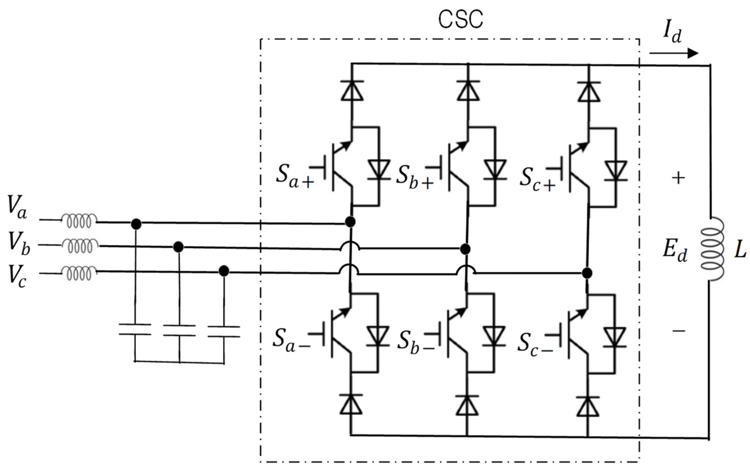
To perform the charge and discharge of active power to and from an SMES, the current converters used should be bidirectional. Three different types of bidirectional current converters can be used to interface the SMES coils with the AC grid [42]. These are namely: (1) set with a voltage source converter (VSC) and a DC chopper; (2) current source controller (CSC); and (3) silicon-controlled rectifier (SCR) “Thyristor”.
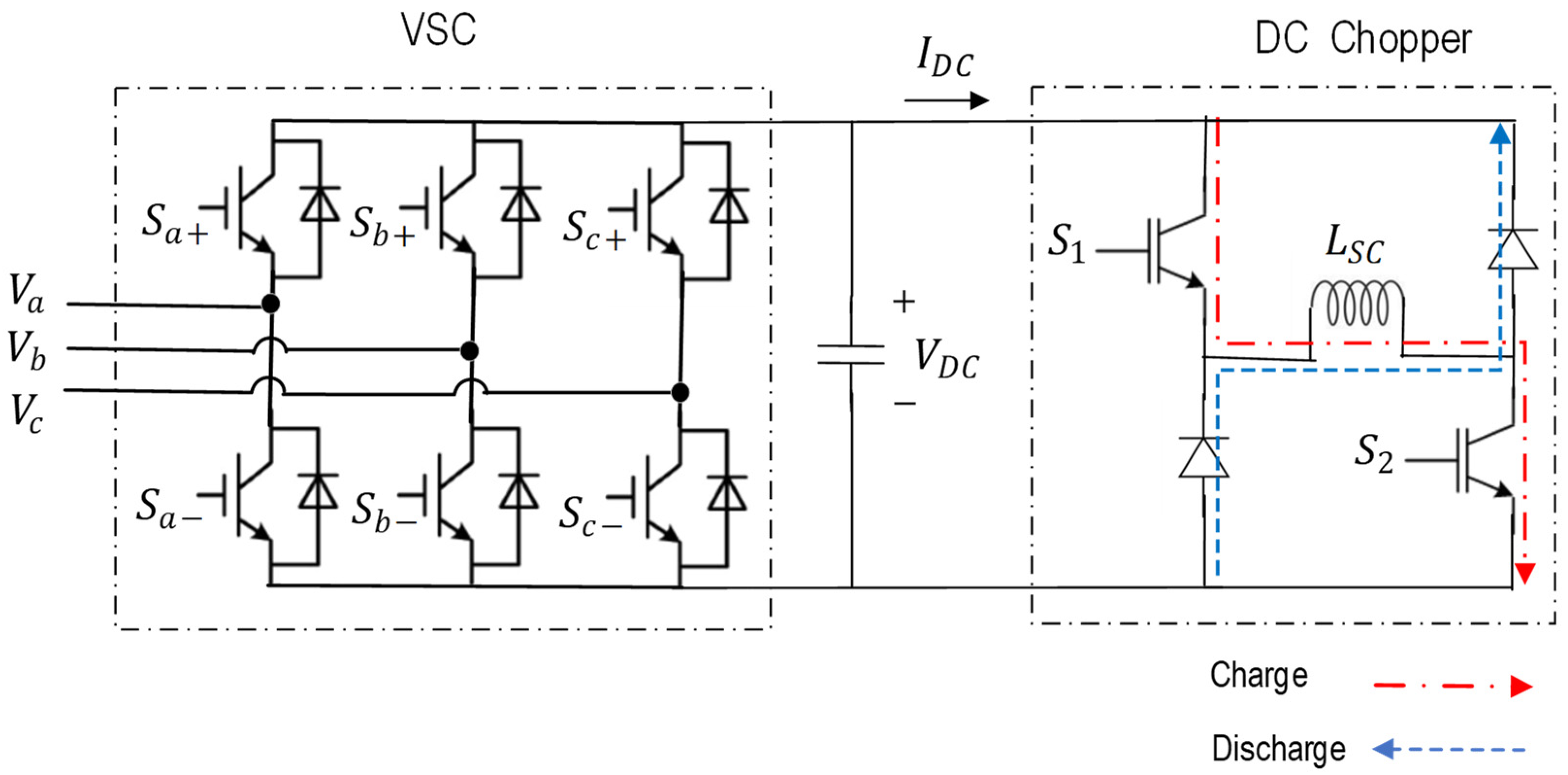
The voltage source controllers (VSCs) are AC-DC voltage converters, with six insulated gate bipolar transistors (IGBT) and six diodes, that allow a bidirectional flow of power from the AC grid to a DC link and vice versa [43]. The six diodes act as a voltage rectifier from the AC grid to the DC-Link. The six IGBT constitute a voltage inverter that is controlled with space vector pulse-width modulation (SVPWM).
The DC choppers control the flow of charged and discharged power to a load that in this case is the superconducting coil (SC) of an SMES. The application of a DC chopper for dynamic DC voltage restorer was presented [44]. Figure 2 shows the set with a VSC and DC-chopper used to connect the SMES to the AC grid controlling the amount of active power charged and discharged to and from the SC. An example of using this set for power fluctuation suppression and active harmonic filtering is presented [45]. To convert the level of AC voltage, this set should be connected via a transformer to the AC grid point of common coupling (PCC).
The SMES could also be connected via an individual DC chopper to the DC-link of double-fed induction generators (DFIG) or the DC-links between inverters and permanent magnet synchronous generators (PMSG) or photovoltaic (PV)-arrays.
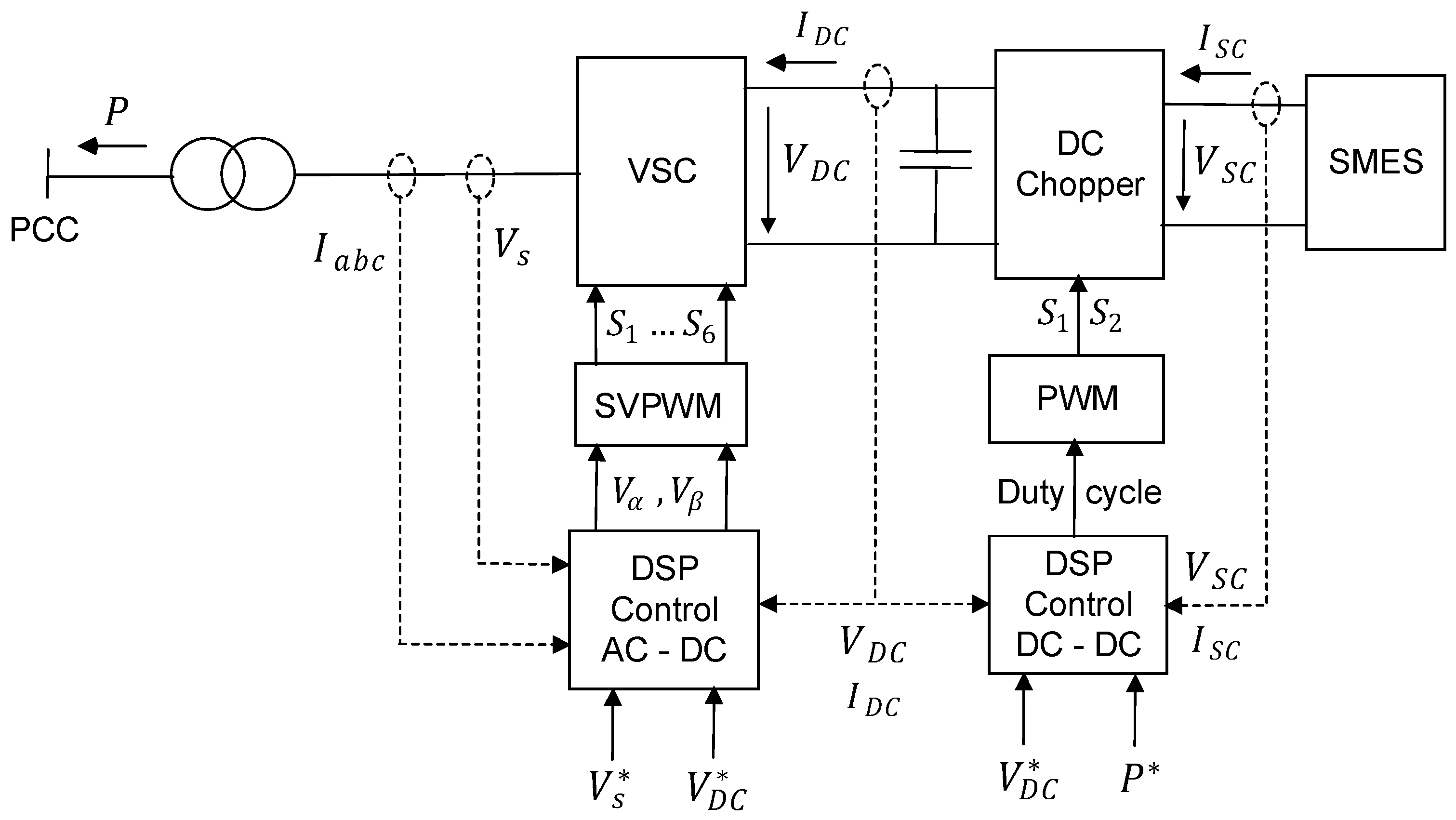
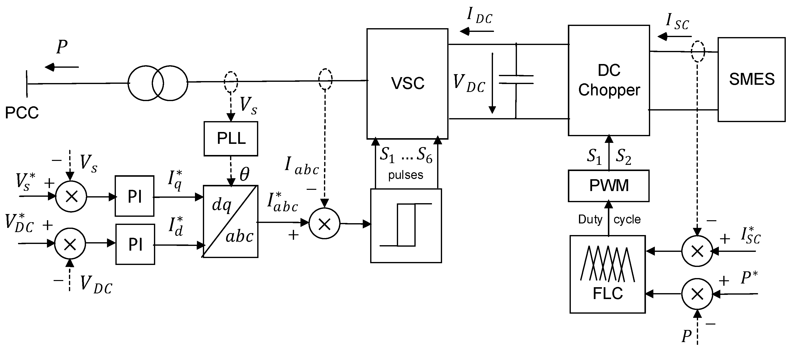
Figure 3 schematizes at a high level the state input variables and reference values in the digital signal processors (DSP) that control the VSC and DC chopper [46].
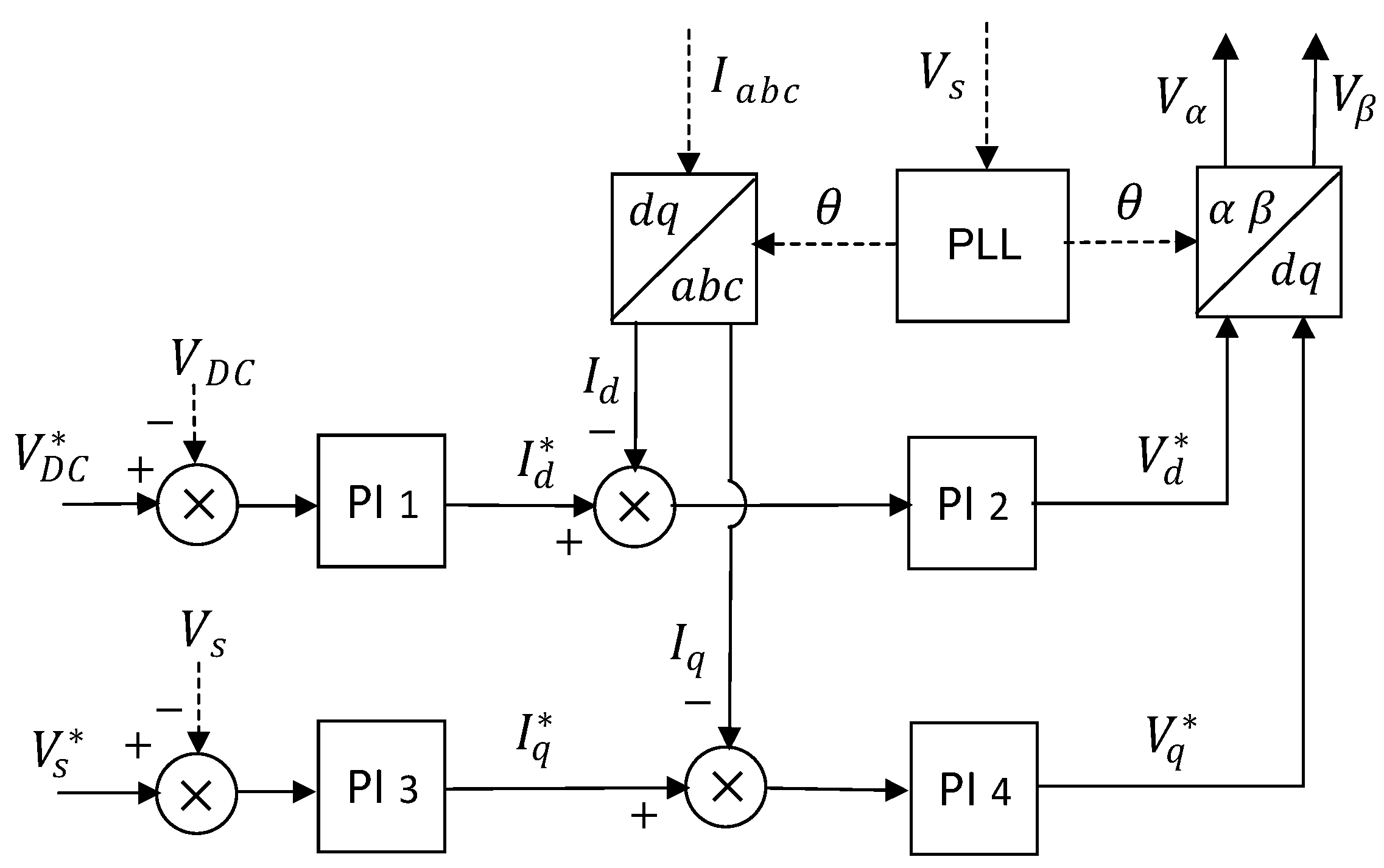
The six gates of the  S a b c +  and  S a b c  are controlled using space vector pulse-width modulation (SVPWM) [47]. The DSP that controls the VSC reads the AC line currents  I a b c , line voltage  V s , DC-bus current  I D C  and voltage  V D C . For the control, we consider reference evolutions for the line voltage  V s *  and DC-bus voltage  V D C * . The Clarke space vector components  V α  and  V β  that generate SVPWM for controlling the VSC are computed by the system presented in Figure 4. This system has four PI regulators that process the current and voltage Park components dq0. A phase-locked loop (PLL) circuit is used to determine the line voltage phase  θ  to compute the Park and Clarke transformations [48].
The DC chopper [44] governs the charging and discharging of active power between the DC-link and the SC. When  S 1  and  S 2  are simultaneously “on” (closed), the current  I D C  is positive flowing from the grid to the SC (red dashed-dotted line). When  S 1  and  S 2  are simultaneously “off” (open), there could be a discharge of the SC when the current  I D C  becomes negative flowing toward the grid direction (blue dashed line) and the two diodes start conducting. If the duty cycle  D , defined by the percentage of time that  S 1  and  S 2  are simultaneously on, is greater than 50% there is a charging effect of the SC. On the contrary, the SC is discharged. When the SC is charged, the memorized current and magnetic field increase. These memorized quantities tend to decrease when the SC is discharged.
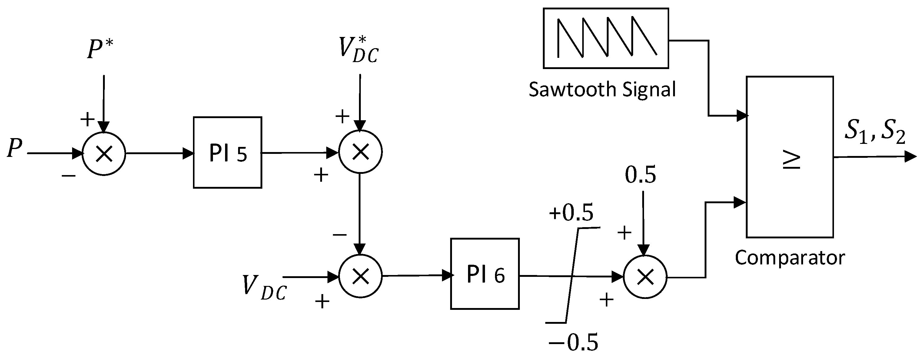
Figure 5 shows the system to compute the duty cycle  D . This system has two PI regulators. The value of  D  is computed by comparing the measured active power  P  and the desired active power  P * . The DC-link voltage  V D C  is regulated to follow its reference  V D C *  and the DC-link current  I D C  adjusted to reach the desired active power. The PI output is compared with a sawtooth signal to generate the duty cycle switching.
The circuit scheme for a CSC is shown in Figure 6. This circuit performs as a rectifier towards the SMES coil and an inverter towards the AC grid. The six IGBT gates  S a b c + , and  S a b c  are controlled by the outputs of a pulse-width modulator (PWM). The duty cycles  D  to control the inverter’s three phases are generated by comparing the phase voltages  V a b c  with a sawtooth signal. When the phase voltages are higher than  E d / 2 , the plus IGBT are directly polarized and the minus IGBT are inversely polarized. Otherwise, when the phase voltages are lower than  E d / 2 , the plus IGBT are inversely polarized and the minus IGBT are directly polarized. The IGBT directly polarized and with gate signal “On” contribute to the increase in the current through the SC and increase in the stored magnetic energy. When there is significant energy consumption by loads on the AC grid side, the power flows from the SC to the grid functioning the CSC as an inverter.
Figure 7 shows an alternative bidirectional AC-DC converter composed of a twelve-pulse silicon-controlled rectifier (SCR) bridge and bypass SCR gate. The charge or discharge of the coil is performed when the firing angle  α  is less or higher than  90 ° .
This time converter was proposed for SMES systems used in the automation of an interconnected hydrothermal generation system [49], optimized tilt fractional order cooperative controllers for preserving frequency stability [50], load frequency control of deregulated power system [51], synthetic inertia system control to enhance frequency dynamic performance in microgrids with high renewable penetration [52] for frequency regulation of power systems with dynamic participation from DFIG based wind farm [53].
With the interconnection of various renewable energy resources and adaptive technologies, the voltage quality and frequency stability of modern power systems are becoming unstable. The dynamic characteristic of SMES allows for rapid exchange of electrical power with the grid during small and large disturbances to address those instabilities.

3.3. Performance and Investment Indicators for Real Systems

A real SMES system with  100   M J  storage capacity was installed at the center for advanced power systems (CAPS) at Florida State University (FSU), and connected to a  4.16   k V  bus from a  5   M V A  generator and a  5   M W  motor [3]. An SMES system with  20   M J  storage capacity and a power of  10   M V A , to compensate for active load fluctuation compensation was implemented and connected to a real  11   k V  power grid in Nikko City, Tochigi Prefecture, Japan [6]. Field test results have shown that the efficiency of this SMES system converter was about  98 %  or more.
Typical SMES-specific power costs are within  200 350   $ / k W  and specific energy costs within  1 k 10 k   $ / k W h  [10]. The ranges  130 515   $ / k W  and  700 10 k   $ / k W h  were also stated [54].
The SMES capital expenditures (CaPex) marginal costs are within:  21 25 %  for the superconducting magnet,  15 30 % , for the power current converters,  8 12 %  for the cryostats, being the reminder for other costs such as buildings, installations, grid connections, and licensing [55].
Studies on return on investment (ROI) were performed for four SMES, two belonging to the San Diego gas and electricity and the other two to the West Coast utilities [55]. ROI values of  17 % ,   24 % ,   46 % , and  71 %  were determined, meaning that all four cases showed a positive net present value (NPV).
Although SMES presented positive NPV on some applications, SMES technology requires broader adoption to enhance its maturity and reduce the investment risks typically associated with emerging technologies. To address this challenge, a new policy framework is needed to incentivize the adoption of SMES, similar to what was implemented for certain renewable technologies. Additionally, with the expected proliferation of renewables and the consequent reduction in system inertia, power quality control will become increasingly challenging. In this context, SMES can emerge as a key technology to mitigate these challenges.
The main challenge of the technology is to reduce the upfront cost, as well as address operation and maintenance, mainly concerning the provision and replenishment of cryogen. However, it should be highlighted that its high efficiency could compensate for maintenance costs and, in time, upfront costs.

4. Frequency Regulation

In a single isolated grid with power from one driving synchronous machine, the frequency varies depending on the non-balance between the active power generation by the synchronous machine  P M  and active power consumption by resistive loads  P L  according to expression (4),
P M P L = d W c d t         ;          W c = I   ω 2 2
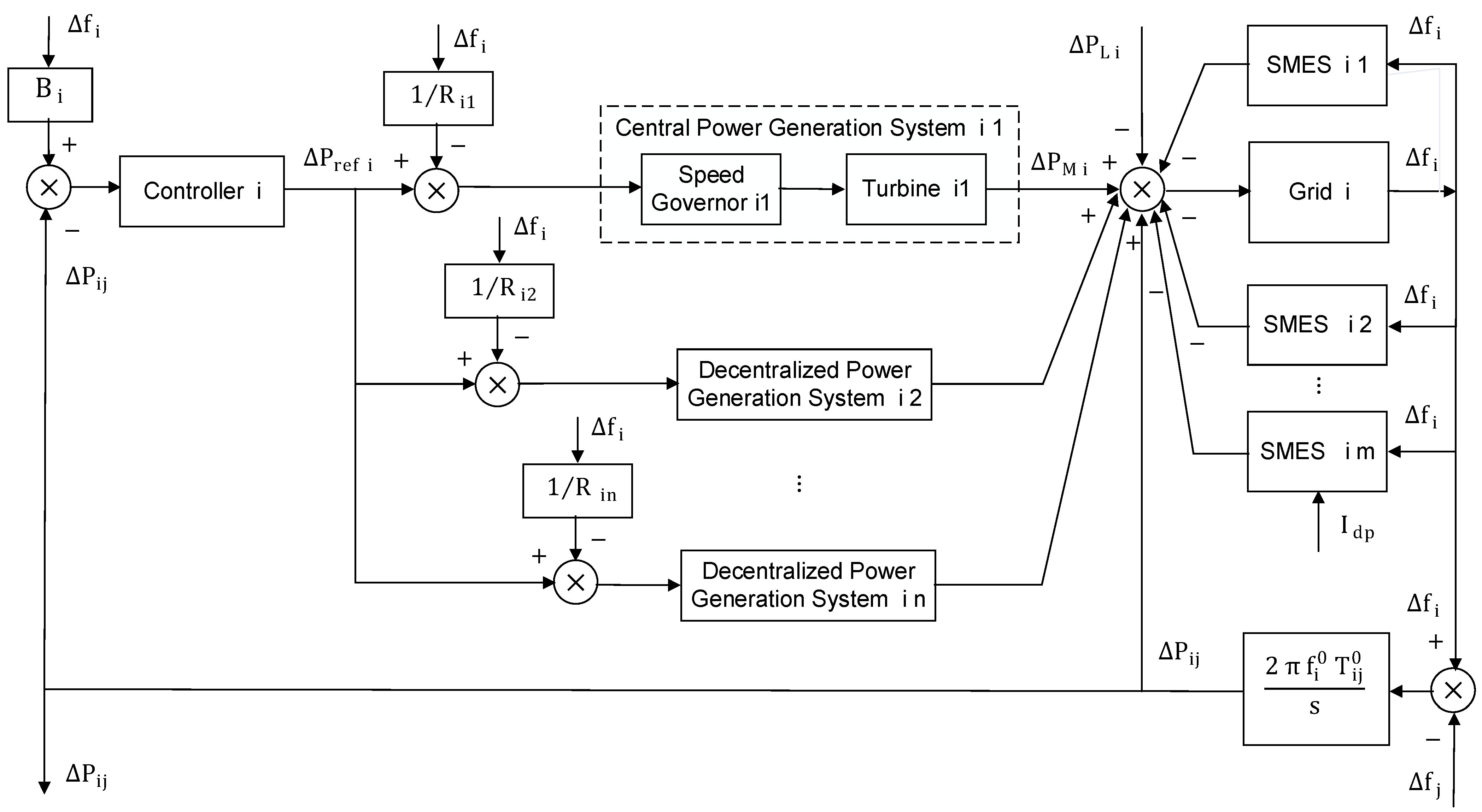
where  W c  the kinetic energy,  I  the moment of Inertia, and  ω  the angular velocity from the synchronous machine rotor mass. So, the grid frequency tends to increase or decrease when the difference  P M P L  is, respectively, positive or negative. Grid areas could be interconnected with other grid areas. Each area could be supplied by one or more central power generation systems and several decentralized power generation systems. When the difference between the active power injected by all generation systems and the active power demanded by all loads is positive the grid frequency tends to increase. Otherwise, when the difference is negative the grid frequency tends to decrease. Frequency regulation can be made by injecting or absorbing active power to compensate for the active power missing or in excess.
In Continental Europe, the standard frequency range should be within  ± 0.05   H z  with a maximum instantaneous deviation of  ± 0.8   H z  and a maximum steady-state deviation of  ± 0.2   H z  [56].

4.1. Global Frequency Regulation System Models and Parameters

The global frequency regulation system for a specific grid area  i  connected to another grid area  j , is shown in Figure 8. The grid area  i  integrates auxiliary SMES systems that perform active power compensation contributing to the grid frequency regulation. The difference between the active power resulting from all synchronous machines and the active power to all loads generates a specific frequency variation  f i  in grid area  i . The speed of the turbines in the central generation system is regulated by a speed governor that controls the valves of the fluid flow to the turbines.
Each grid area  i  is defined by a specific frequency bias constant  B   i  that defines the ratio between grid area active power variation  P i  and the frequency variation  f i . Each central  n  in a specific area  i  is defined by a specific governor speed regulation parameter  R i n  that defines the ratio between the frequency variation and the power to regulate the fluid flow valve. The tie-line delay coefficient  T i j  defines the frequency synchronization time between areas  i  and  j .
Thermal and hydro turbines are generally used in central power generation systems. The transfer function for the set of speed governor and thermal turbine without reheat is given by (5),
1 1 + s   T g   1 1 + s   T t
where  T g  is the speed governor time constant and  T t  the thermal turbine time constant. The transfer function for the set of speed governor and thermal turbine with reheat is instead given by (6),
1 1 + s   T g   1 + s   K r T r 1 + s   T t 1 + s   T r
where  K r  and  T r  are, respectively, the gain and time constant to account for the reheating effect.
The transfer function for the set of speed governor and hydro turbine is given by (7),
1 1 + s   T 1       1 + s   T R 1 + s   T 2       1 + s   T w 1 + 0.5   s   T w
where  T 1  is the time constant of the hydraulic governor,  T 2  the time constant of the hydraulic droop transient,  T R  the reset time and  T w  the water starting time of the hydro turbine.
The transfer function for the grid, having as input the difference between powers from generator machines and the powers to the loads and as output the resulting frequency variation, is given by (8),
K p 1 + s   T p
where  K p  and  T p  are the grid gain and time constant.
Several frequency regulation systems using SMES were defined. An optimized hybrid fractional order controller was proposed to model SMES in the frequency regulation of multi-area power systems [57]. The modeling of magnetic energy storage in frequency stabilization [58], frequency control of multi-source multi-area hydrothermal systems [59], load frequency control of power systems with renewable integration [60], and frequency control of multi-area power systems with hybrid energy storage devices including SMES was studied [61]. Also, the use of SMES in the predictive load frequency control of hybrid multi-interconnected plants comprising renewable energy was discussed [62], as well as frequency regulation of solar and wind-integrated multi-area systems [63], the optimized fractional-order PI-based SMES to perform frequency control of a PV/Wind-Integrated system [64], and the automatic generation control with SMES in power systems [65]. An optimal design frequency fluctuation control system with SMES unit was presented [66]. Table 2 states typical values for the several model parameters in the global frequency regulation system.
The transfer functions for wind, PV [21], and diesel [62] decentralized power generation systems are expressed, respectively, by (9), (10) and (11),
G w = K p w 1 1 + s   T p w 1 1 + s   K p w 2 1 + s   T p w 2     K p w 3 1 + s  
where  K p w 1 K p w 2 , and  K p w 3  are the gains,  T p w 1 T p w 2 , and  T p w 3  are the time constants of the wind plant system.
G P V = K P V 1   s + K P V 2 s 2 + T P V 1   s + T P V 2
where  K P V 1 , and  K P V 2 , are the gains  T p w 1 , and  T p w 2  are the time constants of the PV system with maximum power point tracking (MPPT).
G D = K d i e s   1 + s 0.025   s 2 + s
where  K d i e s  is the gain of the diesel generator. Typical values for the gains and time constants in expressions (9)–(11), are stated in Table 3 [62].
Several types of control such as proportional-integral (PI) proportional integral derivative (PID), fractional order proportional integral derivative (FOPID), and tilt integral derivative (TID) were tested for the secondary controller to calculate  P r e f  [57].

4.2. Superconducting Magnetic Energy Storage System Models

Frequency regulation using SMES is performed by storing or restoring active power from or into the grid to maintain the system frequency. Figure 9 shows the two-stage lead-lag system model to characterize the SMES in frequency stabilization. The gain and time constants of the SMES coil are given by  K S M E S  and  T S M E S . The time constants of the two-stage lead-lag compensator are defined by  T 1 T 2 T 3 , and  T 4 . Table 4 states typical values for these parameters.
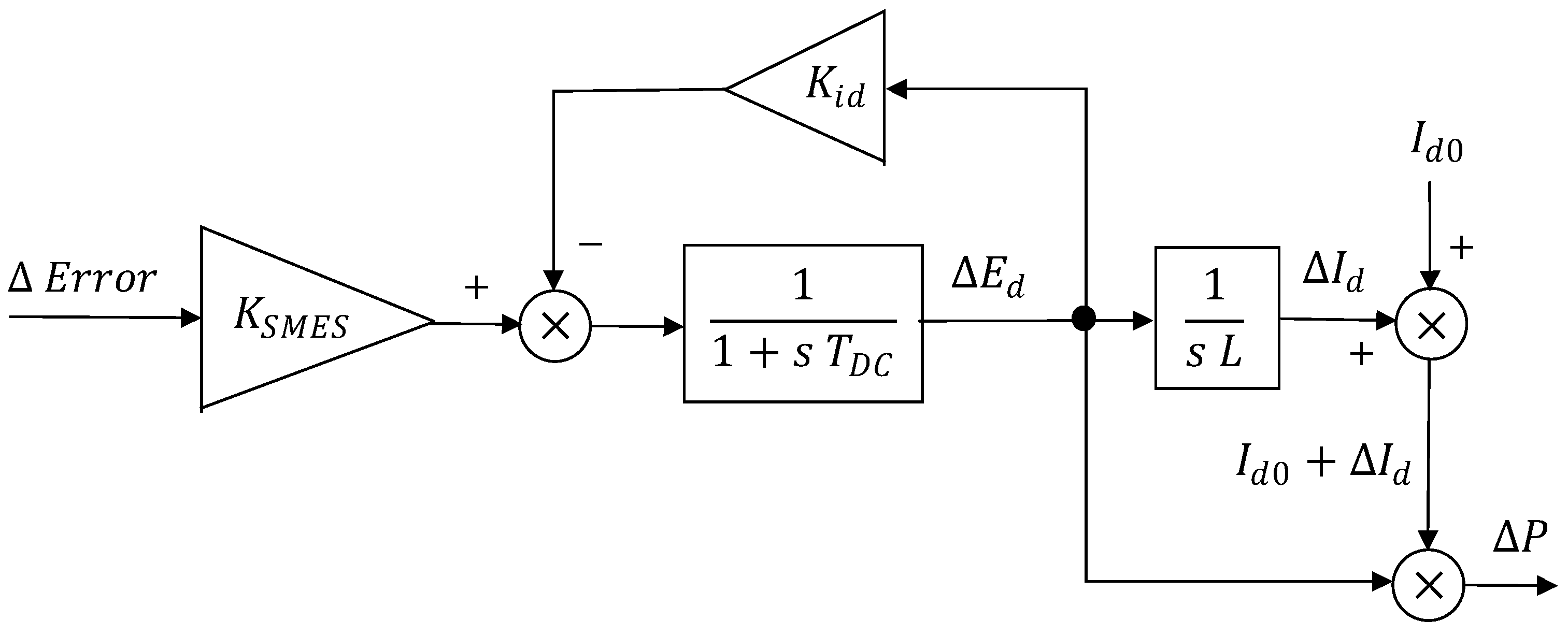
Figure 10 shows the SMES system model with fractional-order proportional integral (FOPI). The converter gain and time delay are given by  K S M E S  and  T D C . Quantities  E d  and  I d  are the incremental change of the coil DC voltage and current. The DC bias to the SMES coil is given by  I d 0 . The control loop gain is given by  K i d .
The input  E r r o r , corresponding to the area control error (ACE), is given by expression (12), where  B  is the area frequency bias constant  f  the frequency variation and  P t i e  the sum of the power variations in the tie interconnections to other grid areas.
E r r o r = B   f + P t i e
Table 5 states typical parameter values for the SMES system model with FOPI.
The modeling of an SMES system to regulate the frequency with an equivalent PI control was proposed and studied [66]. The optimal proportional and integral gains,  K P  and  K I , of the SMES equivalent PI control were computed, first using the Ziegler–Nichols method, and then using a fuzzy logic controller with rules that look at the frequency variation  F  and the output power variation  P .

4.3. Systems Overview and Development Challenges in Frequency Control

Several studies on frequency regulation with SMES have been conducted. Some proposed that SMES system models are based on PI lead-lag control and others on FOPI. Table 6 classifies the studies on frequency regulation with SMES systems in terms of: (i) the number of grid areas considered; (ii) types of centralized and decentralized generation resources by area; (iii) system control level (primary or secondary); (iv) type of SMES current conversion interface; and (v) type of SMES system control.
Most of the scenarios considered systems of two grid areas. There was one study on a system with four grid areas [61] and another on a system with six grid areas [62]. Decentralized renewable power generation was considered in half of the frequency regulation studies with SMES. The twelve-pulse SCR bridge was considered as an SMES current converter interface for most of the frequency regulation studies. Concerning the SMES system control, the FOPI and PI lead-lag are the most common systems used. There was one study using PID [57] and another study using a PI-FLC [66].
In terms of research challenges, studies are necessary on the:
(1)
Optimization of the SMES energy storage capacity looking for the renewable resources potential and expected load demanding profile.
(2)
Use of predictive control for anticipating the possibility that the maximum frequency deviation is exceeded based on the prediction of renewable resources evolution.
(3)
Study and assessment of SMES system control techniques for frequency regulation on grids with significant renewable power generation.

5. Power Oscillation Damping

Power oscillation results from the variation of the synchronous generators’ rotor speed mainly after the connection of synchronous generators (SG) or connection/disconnection of significant loads or grid sections. Also, during the connection/disconnection of decentralized renewable power generation plants including DC-AC converters, characterized by different dynamics.

5.1. Power Oscillation Damping Systems Using Superconducting Magnetic Energy Storage

The use of an SMES system with a current source controller (CSC) to damp power oscillations in the connection between an SG and the grid utility was studied in [67]. Figure 11a shows the general unifilar connection scheme with a current source-controlled SMES connected to the point of common coupling (PCC) in between the SG and the connection to the grid utility. When the SG is connected to the power grid there is a transient period when there is an oscillation on the generated active power  P  traduced by an oscillation on the phase-angle  δ  around the target phase-angle  δ o . Consequently, there is oscillation of the angular velocity  ω r  around the synchronous rotor velocity  ω r o . There is transmission of active power  P  towards the power grid, if the phase-angle  δ o  corresponding to the difference between the SG electromotive force angle and the PCC voltage angle is positive. Also, the difference  β  between the PCC voltage  V  and grid voltage  U  should be positive.
A proportional Integral controller with Integral alleviation (PI-IA) is proposed for the CSC to control the SMES direct current variation  I s c  depending on the verified SG rotor speed variation  ω r . The PI-IA transfer function is expressed by (13). According to [67], optimal values for the proportional, integral, and back loop gains are, respectively,  k p = 470 k i = 10 , and  k b = 0.056 . A deep reinforcement learning (DRL)-based agent was proposed to obtain the optimal parameters. [68]. Figure 11b schematizes the system diagram of the PI-IA in the CSC.
G C S C = s   k p + k i s + k i   k b  
A simple conventional PI control could cause the deep SMES charging or discharging not to effectively dampen the power oscillation.
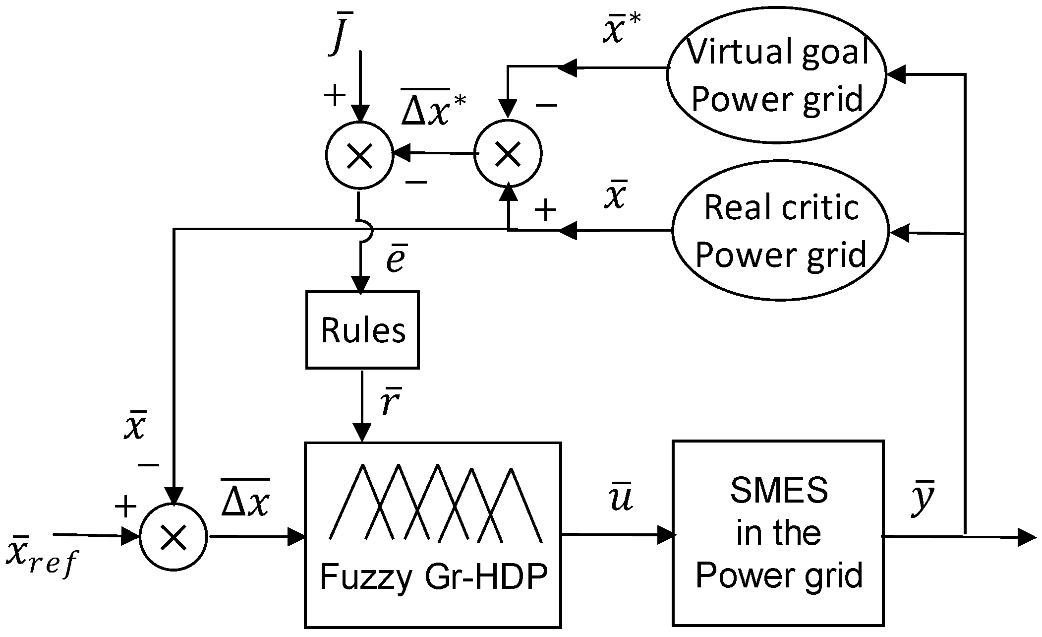
The use of SMES with an adaptive learning controller by using a fuzzy-based goal representation heuristic dynamic programming (Fuzzy-GrHDP) algorithm to perform power oscillation damping on a grid with several generators looking for other SG states is proposed in [69]. The Fuzzy-GrHDP algorithm belongs to the adaptative critic design (ACD) family. The differences between the rotor angles of different generators  Δ ω i j , that is, their synchronous deviations, are considered as input entries. Also, the delays  τ i j  that account for the response time due to transient changes on the state of different SG are considered as input entries. The state input vector  x ¯  is expressed as (14), where  N S G  are the number of synchrounous generators throughout the grid.
x ¯ = Δ ω 12 , , Δ ω i j , τ 12 , τ i j       ;       i j      ;      i , j = 1 , I , N S G  
The fuzzy logic looks at the deviation  x ¯  between the actual state input vector  x ¯  and the desired reference state input vector  x ¯ r e f  and generates the control vector  u ¯  with the set of current increments  Δ I s c i  to be set on the different SMES throughout the grid nodes as expressed by (15), where  N  is the number of SMES in the power grid.
u ¯ = Δ I s c 1 , , Δ I s c N  
Then, an output vector  y ¯  is defined by the set of increments of injected active power  Δ P i  by the different SMES in the power grid, as expressed by (16).
y ¯ = Δ P 1 , , Δ P N  
The set of increments of injected active power  y ¯  creates a new state of synchronous deviations  x ¯  between the different SG in the real critical power grid. Also, the values of the output vector  y ¯  are used as inputs into a virtual goal power grid to compute optimal values of synchronous deviations  x ¯ * . The difference vector  x * = x ¯ x ¯ *  is then compared with the objective vector  J ¯  generating an error vector  e ¯  that is used as input to update the vector  r ¯  of fuzzification and de-fuzzification rules. The increment in the rules  r ¯  is given by a variation in the set weight functions  μ ¯  calculated according to (17).
r ¯ = μ ¯ · e ¯ r ¯  
The new vector of synchronous deviations  x ¯  is then compared again with  x ¯ r e f  generating new input  x ¯  for the Fuzzy-GrHDP inference system. Figure 12 schematizes the distributed control using Fuzzy-GrHDP of multiple SMES looking for the synchronous deviations between different SG in a power grid.
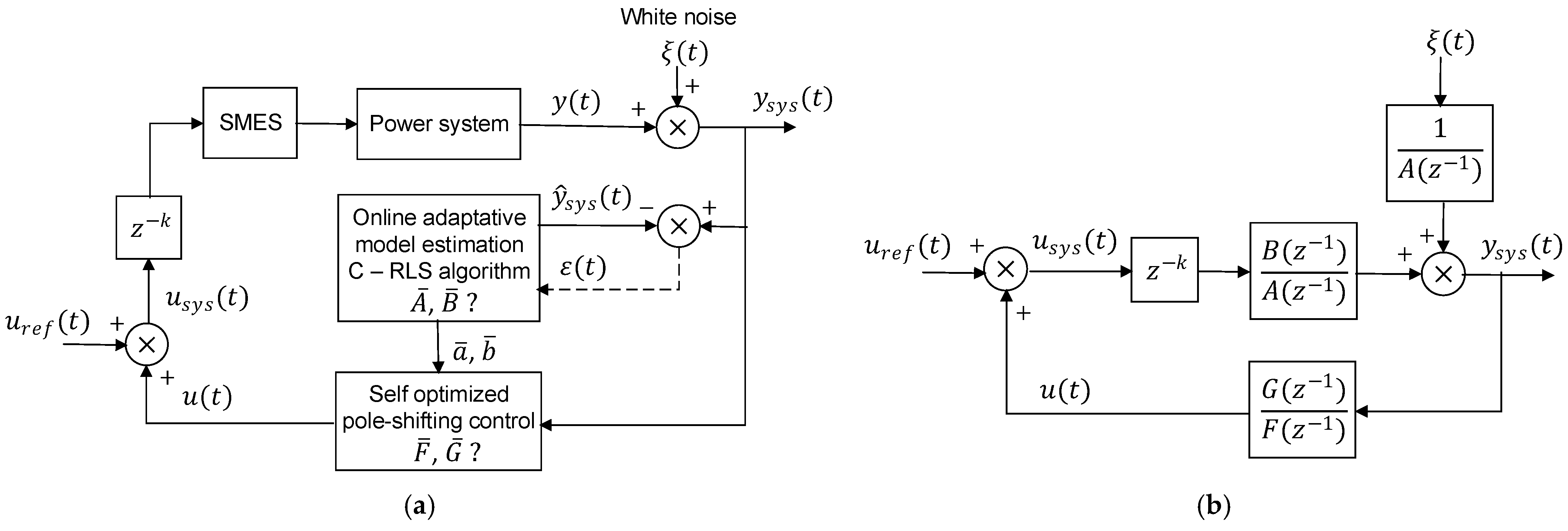
Discrete adaptive self-optimizing pole-shifting controls were proposed in [70] to mitigate the power oscillations at the connections between different areas supplied by different synchronous generators. An adaptive pole-shift control technique was proposed [71]. The dynamics from renewable power generation (like Wind and PV) inverters are different than from SG. Hence, the connection/disconnection of renewable power generation inverters imposes different power oscillation dynamics. This discrete adaptive self-optimizing pole-shifting is a flexible technique for use in SMES control to damp power oscillations when the produced power is not only from SG but also from inverters of renewable power generation plants. Adaptative control enables damping from different power oscillation dynamics, not only in the connection of SG but also in the connection of inverters from renewable resources.
Figure 13a shows the principle of the discrete adaptative control system. Figure 13b shows the corresponding z-transform system diagram. The control input  u ( t )  is the current variation  Δ I s c , and the system output  y ( t )  the active power variation  Δ P .
The coefficients of the numerator  b ¯ = b 1 , , b N b  and of the denominator  a ¯ = a 1 , , a N a  from the open loop transfer function are estimated using an adaptative constrained recursive least square (C-RLS) algorithm. From the open loop poles are calculated the closed loop poles using a self-optimized pole-shifting, so that the closed-loop system becomes stable and its damping is maximized (poles with a negative real part of maximum amplitude). The coefficients of the numerator  g ¯ = g 1 , , g N g  and denominator  f ¯ = f 1 , , f N f  of the back loop transfer function are then estimated based on the optimized pole-shifting and trying to match the gain between the open loop system inputs  u ( t )  and outputs  y s y s ( t ) , according to Equation (18).
u ( t ) y s y s ( t ) = G ( z 1 ) F ( z 1 )

5.2. Systems Overview and Development Challenges in Oscillation Damping

Several SMES systems for power oscillation damping have been proposed and studied. A system with CSC using PI-IA to damp power oscillations in the connection between an SG and the grid utility was studied [58,59]. Another system uses a distributed FLC with GrHDP to damp power oscillations based on the measurements of synchronous deviations between rotor angles of different SG in the grid [69]. An adaptative control was proposed to damp power oscillations from the dynamics of WTG [70]. Another was based on the adaptative pole-shifting technique [71]. Finally, an SMES system using multi-loop feedback control to cancel the resonant peak of the LCL filter in the link between an SG and the PCC was proposed and studied [72]. Table 7 classifies the different SMES systems identified for power oscillation damping in terms of: (i) point of connection to the grid; (ii) type of current converter interface; and (iii) adopted SMES control strategy.
The SMES systems proposed in [67,68,69] are applicable for grids with power generation from SG. The SMES systems based on adaptative control [70,71], also apply to grids with power generation from intermittent renewable energy resources characterized by dynamics different from SG.
In terms of research challenges, studies are necessary on the:
(1)
Optimization of the SMES energy storage capacity for a specific damping coefficient.
(2)
Analysis of the damping gain from using the distributed Fuzzy-GrHDP on a grid with several SG, looking for the synchronous deviations between different SG, instead of performing the power oscillation damping based only on the local generator phase angle.
(3)
Use of distributed adaptative control SMES systems, with adaptative algorithms based on the measurements of power oscillations also from other decentralized renewable power generation plants in the same distribution grid.

6. Power Fluctuation Suppression

The integration of even more renewable power resources, such as photovoltaic (PV) and wind turbine generators (WTG), causes power fluctuation due to the inconstancy of the power injected into the grid. A predictive control model to manage power flow on a hybrid wind-PV and diesel microgeneration power plant with additional storage capacity was proposed [73]. The wind forecast at medium voltage distribution networks was performed [74]. Also, with the increase in the number of electrical vehicles (EVs), there are peaks of consumption during specific periods when the EV batteries are charged [75]. With the increase in the imbalance between production and consumption, there is an increase in power fluctuation [76].

6.1. Power Fluctuation Suppression Systems Using Superconducting Magnetic Energy Storage

This subsection presents a review of SMES systems to mitigate power fluctuation, thus increasing the stability of power systems. SMES systems may connect to the PCC of the AC power grid utility using a VSC and DC chopper. SMES may also connect to the DC-link of DFIG or DC  μ -grids between inverters and PMSG or PV arrays, using only a DC chopper.
An SMES with YBCO and BSCCO coils connected to the grid using a VSC and DC chopper controlled by a dual processor with a digital signal processor (DSP) and a micro-programmed control unit (MCU) was implemented and tested to compensate for the power fluctuation [46]. The VSC is commanded by SVPWM and the DC Chopper by PWM with a scheme like the one presented in Figure 3.
A fuzzy logic-based and hysteresis current system is proposed in [77] to control the energy exchange between an SMES coil and the DFIG of wind turbine generators (WTG) to reduce fluctuations of the generated power, shaft speed, electromagnetic torque, and the DC-link voltage. The SMES is connected to the DC-link of the DFIG via a DC Chopper, which, with an appropriate fuzzy logic controller (FLC), manages the energy exchange between the SMES and the power system. The set of fuzzy logic rules is developed based on the deviations of the DFIG-generated power  P G = P G P G *  and of the SMES current  I S C = I S C I S C * , with the objective of balancing the SMES current  I S C  with the generated power  P G . The desired SMES current increment  I S C  is obtained by setting a specific PWM duty cycle to the DC chopper control.
The hysteresis current controller (HCC) generates gate pulses  S 1 S 6  for VSC switching based on the comparison between the reference line current  I a b c *  and the measured line current  I a b c  to minimize voltage flicking and power fluctuation. The reference line’s current  I a b c *  determined from the reference direct current  I d *  and reference quadrature current  I q *  with the Park’s inverse transformation. These last two current quantities are obtained using proportional-integral (PI) transformation from the line voltage deviation  V s = V s * V s  and the DC-link voltage deviation  V D C = V D C * V D C , respectively. Figure 14 schematizes this compensation system with fuzzy logic and hysteresis current-based control.
A similar fuzzy logic basic system was proposed in [78]. In this last one, the FLC that controls the DC chopper looks at the fuzzy logic rules developed based on the deviations of the wind speed  V w i n d = V w i n d V w i n d *  and of the SMES current  I S C = I S C I S C * , to balance the SMES current  I S C  with the DFIG power curve. The FLC rules help to decide on the appropriate duty cycle to command the DC chopper PWM switching. The adopted VSC switching control is based on the scheme of Figure 3.

6.1.1. Wind Power Generation

The doubly fed induction generator (DFIG) wind turbine presents the problems of generating power fluctuation due to the power generation inconstancy and low voltage ride-through (LVRT) performance. The second consists of the ability to continue connected to the grid during periods when the grid voltage is under the regulated range during short-circuit fault periods, which is not desired. This ability of DFIG is also known as fault ride-through (FRT).
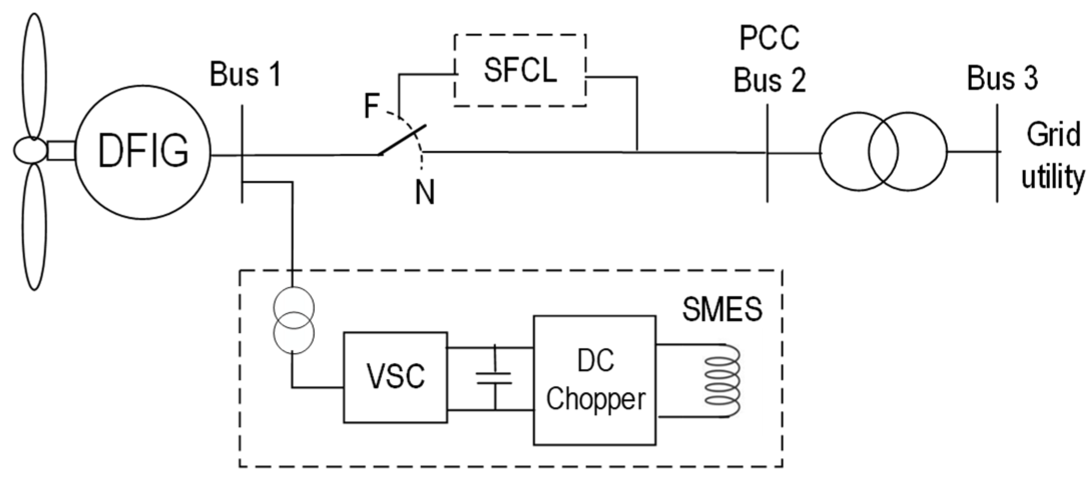
The simultaneous use of SMES with the DC chopper and VSC connected to the AC bus to mitigate power fluctuations and a separate cooperative superconducting fault current limiter (SFCL) that protects the connection to the grid during short-circuit faults was proposed and studied in [79]. Figure 15 illustrates the unifilar scheme of such a system, with simultaneous use of SMES connected with the VSC and DC chopper to the AC bus and cooperative SCFL. When a fault occurs, the SFCL is used to limit the fault current, alleviate the terminal voltage drop, and transient power fluctuation, and avoid the DFIG continuing operating on LVRT conditions. Subsequently, the remaining power fluctuation is suppressed by the SMES. The resistive value of the SFCL as well as the inductance of the SMES coil are simultaneously optimized to minimize the sudden increase in the DFIG kinetic energy during faults, the SFCL energy loss, and the output power fluctuation.
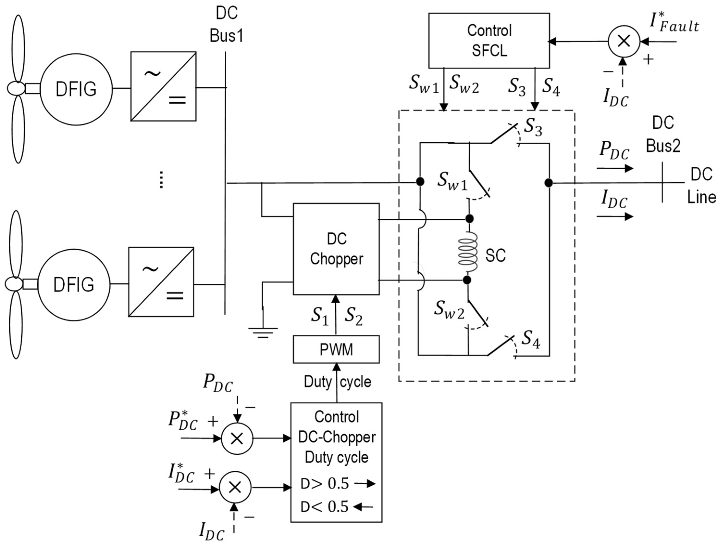
A circuit configuration using superconducting magnetic energy storage with fault current limiting function (SMES-FCL) in the DC microgrid of a DFIG was presented in [80]. Figure 16 shows the unifilar scheme of such a circuit configuration. The SMES-FCL circuit mainly consists of two DC choppers with a common superconducting coil (SC). During normal operation, the SMES-FCL acts as the SMES unit to suppress the power fluctuation of DFIG. When severe faults occur in the system, the SC is automatically used as the fault current limiter. Consequently, the combined SMES-FCL system compensates for power fluctuations and performs protection during short-circuit faults. The energy function method is used to formulate the optimization problem of SC inductance, initial stored energy, and the proportional-integral control parameters of DC-DC choppers. The SMES-FCL in the DC  μ -grid of DFIG enhances the LVRT capability and regulates power fluctuation.
The logic switching scheme for the SFCL switches  S w 1 S w 2 S 3 , and  S 4  is schematized in Figure 17. Switches  S w 1  and  S w 2  present simultaneously the same logic state. This is also true for switches  S 3  and  S 4 . These two sets with two switches each present simultaneously opposite states. When  S w 1  and  S w 2  are both “on” (closed),  S 3  and  S 4  are both “off” (open) and the SC is working as SFCL. In the other case, the SC is connected to the DC Chopper and works as an SMES. In this last case with the SC serving as SMES, when switches  S 1  and  S 2  of the DC chopper are both “on” and the SMES is in the charging mode. Otherwise, when  S 1  and  S 2  are both “off”, the SMES is in the discharging mode.
The control that determines the duty cycle  D  of the PWM that commands  S w 1 , the DC chopper switches  S 1  and  S 2  is based on the logic scheme presented in Figure 4.
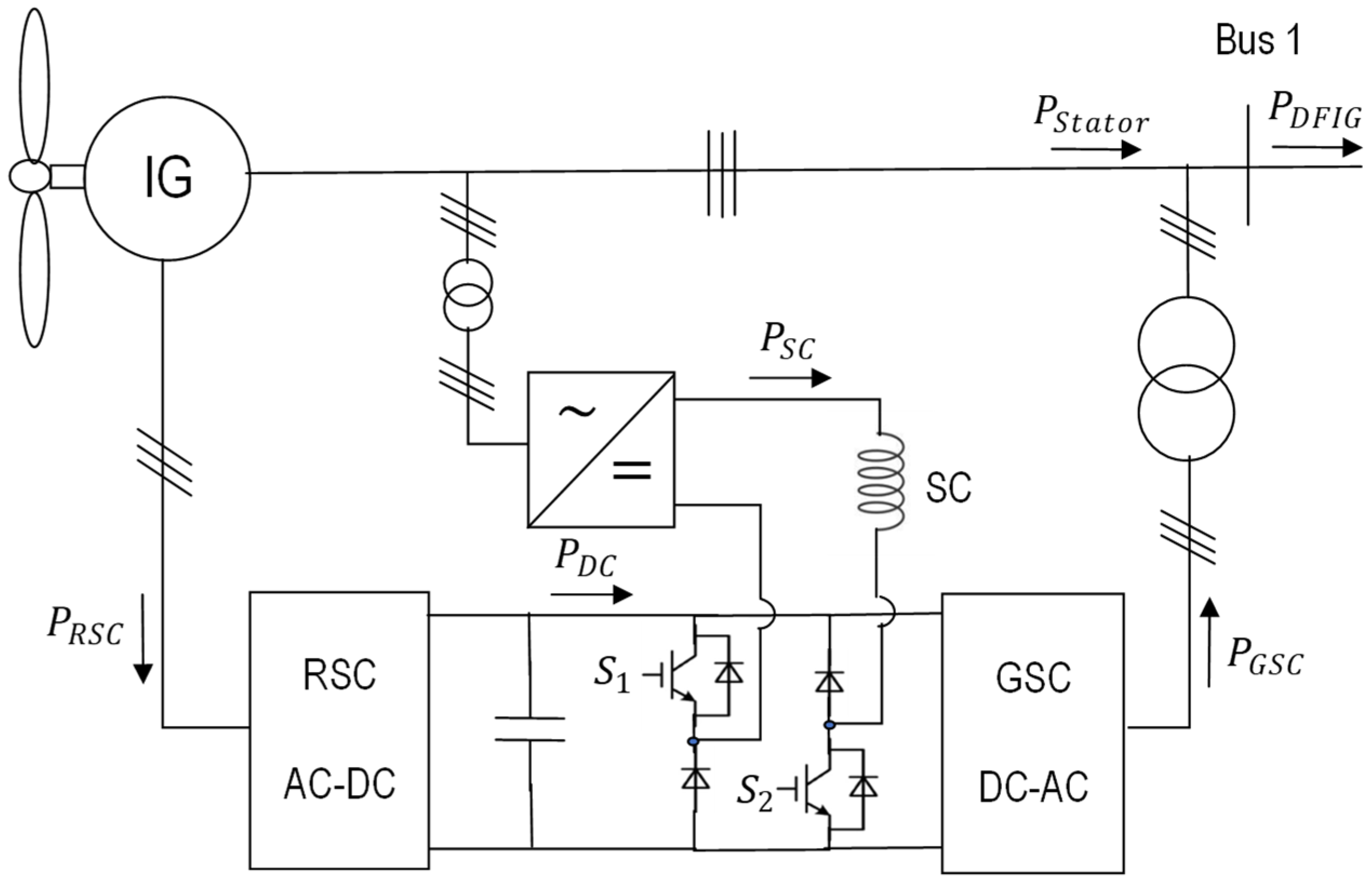
Figure 18 shows the scheme of a system with the optimal superconducting coil (SC) integrated into the DC-link of the DFIG wind turbine, to avoid operation with FRT and suppress output power fluctuation, that was proposed and studied in [81]. The SC is connected using an AC-DC converter from the DFIG stator terminal to the DC  μ -grid between the rotor side converter (RSC) and the grid side converter (GSC). A DC chopper controls the exchanged energy to and from the SC. During normal operation, the SC acts as an energy storage device to exchange energy with the system so that the power fluctuation of the DFIG wind turbine can be alleviated. When the switches  S 1  and  S 2  of the DC chopper are both “on” (closed) the SC is charged. Otherwise, the SC is discharged. When severe short-circuit faults occur in the system, the SC is used as the current limiting inductor to suppress both overcurrent in the rotor and stator, and overvoltage in the DC link of the DFIG.
A particle swarm optimization (PSO) was performed to optimize the inductance of the SC, the initial current, the initial necessary stored energy in the SC, and the proportional-integral (PI) parameters of the GSC and RSC, to achieve the following objectives: (1) alleviation of the output power fluctuation; (2) reduction in the DC-link overvoltage; and (3) suppression the overcurrent in both stator and rotor. The DFIG wind turbine with the optimal SC maximizes the power suppression effect and enhances the FRT capability. Although the cost of integrating the optimized SC into the DFIG, this solution has the benefits of smoothing power fluctuations, avoiding the operation with FRT, limiting fault current, and improving the power system’s transient stability.
An interline AC-DC unified power quality conditioner (UPQC) protection device with SMES was proposed and designed to avoid the operation with low voltage ride through (LVRT) and smooth output power for doubly fed induction generator (DFIG)/permanent magnet synchronous generator (PMSG) hybrid wind energy conversion system (WECS) [82]. The AC side of the proposed UPQC is connected in series with the terminal of DFIG as a dynamic voltage restorer (DVR). The DC side of the UPQC is connected in parallel with the DC bus of PMSG for DC bus voltage maintenance and output power adjustment.

6.1.2. Photovoltaic Power Generation

Connecting intermittent sources to the grid introduces challenges in various technical aspects such as power quality, protection, generation dispatch control, and reliability. In this context, leveling intermittent source output is necessary to maintain the grid’s stability. A comprehensive literature review on problems when intermittent PV is connected to the grid and the methods of smoothing the output power fluctuation from PV was performed [83].
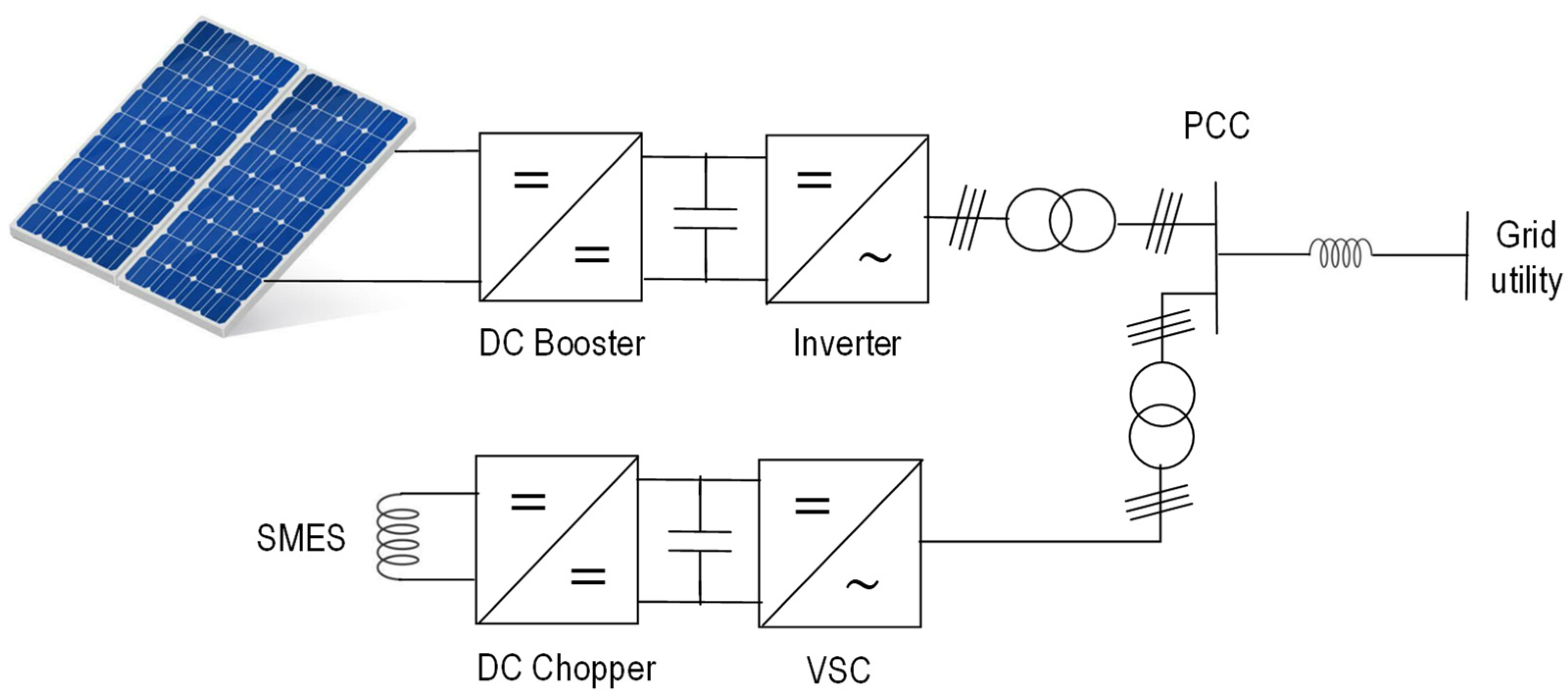
An SMES with the dual functions of active power storing for smoothing power fluctuations and shunt active power filter (SAPF) for constraining harmonic and unbalanced currents in a photovoltaic (PV) microgrid was proposed and studied [45]. As shown in Figure 19, the SMES is interfaced with a DC chopper and VSC to the PCC. A control scheme like the one shown in Figure 14, using PI-based and hysteresis current control (HCC) of the VSC and FLC of the DC chopper was proposed for this system.
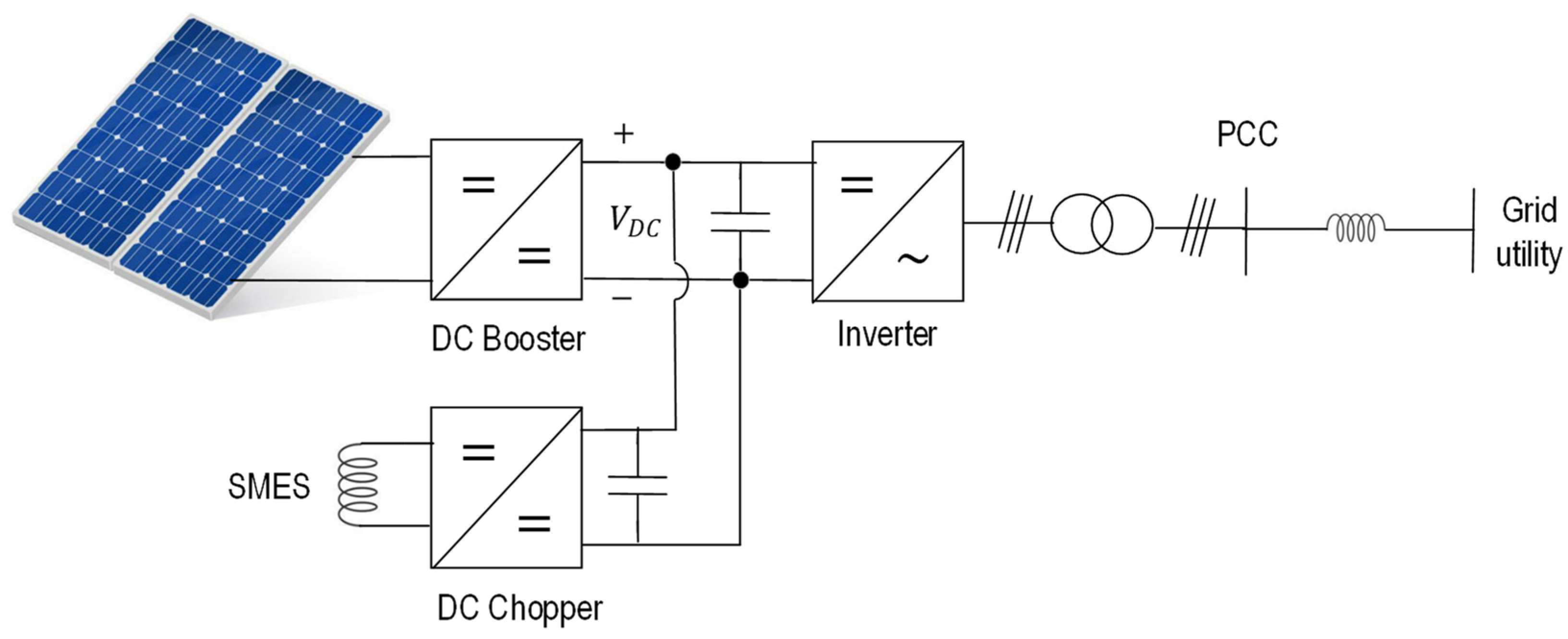
Figure 20 shows another system with SMES connected with a DC-chopper to the DC-link between the DC booster and inverter of a PV system to perform power fluctuation suppression and active current filtering control that was proposed in [84]. An improved sliding mode controller (SMC) was developed for the DC chopper to stabilize the DC-link voltage. The stability of the proposed SMC controller was demonstrated based on the Lyapunov stability theory.

6.2. Systems Overview and Development Challenges in Fluctuation Suppression

Several SMES systems identified to mitigate the power fluctuations caused by the intermittency of renewable resources such as PV and wind are stated in Table 8. For the ones that connect to the AC grid, the VSC was controlled by a PI following the grid line reference voltage  V S * . In some of the VSCs, switches were commanded using SVPWM. In other VSCs, switches were commanded using HCC. The DC chopper switches were commanded using PWM controlled by a PI following the DC link reference voltage  V D C *  or the DC link reference current  I D C * . Some of the DC chopper switches were commanded using PWM controlled by FLC. The use of SMC based on the Lyapunov stability theory was proposed for controlling the DC chopper to stabilize the DC-link voltage.
In some DFIG, the SMES coil becomes a SFCL when the line current exceeds a maximum reference value  I F a u l t  to disconnect the DFIG during short-circuit fault periods because of its LVRT capability [79,80,81].
In terms of research challenges, the following are necessary:
(1)
Studies comparing the efficiency, time-response and fluctuation suppression precision of SMES systems connected via VSC and DC chopper to the AC grid bus or via only a DC-Chopper to the DC-link of DFIG or to the DC  μ -grid of wind or PV generation plants.
(2)
Studies of the transient effects when a superconducting magnet with both SMES and SFCL functionalities, changes from a specific stored magnetic energy to support a short-circuit fault current.
(3)
Studies comparing the precision of SVPWM and HCC modulations on the control of VSC in an SMES system for power suppression.
(4)
The proposal and study of adaptative control techniques that continuously adapt to the system response and improve the power fluctuation suppression.

7. Voltage Sags and Flickering Compensation

Voltage sags and flickers are caused by reactive power decompensation. In Continental Europe, the standard voltage range should be within  ± 5 %  [85].
An SMES voltage sag compensation system with  0.3   M J  NbTi magnet able to absorb or inject reactive power that compensates for the phase angle deviation created by reactive loads, was designed and implemented [86]. The performance of an SMES System with a DC-chopper and VSC with hysteretic voltage control (HVC) to compensate for the steady voltage sag caused by phase angle deviation was evaluated [87]. An SMES system with a  3   M J  superconducting magnet, a DC-chopper with FLC, and a VSC with HVC, to reduce the sag and flicker was studied [88].

8. Active Harmonics Filtering

With the increasing deployment of power electronic converters, current harmonics are injected into the grid affecting the quality of the supplied energy. Thus, it is even more necessary to perform current harmonics filtering to not affect sensitive consumer loads. Table 9 resumes the maximum voltage total harmonic distortion (THD) depending on the voltage level according to [89].
Passive or active filters can be used to remove current harmonics from the grid. Passive filters are based on the creation of a lower impedance absorption path for higher frequency current harmonics. Active filters are based on the cancellation of the harmonic content by subtraction of symmetric amplitude harmonics.

8.1. Active Harmonics Filtering Systems Using Superconducting Magnetic Energy Storage

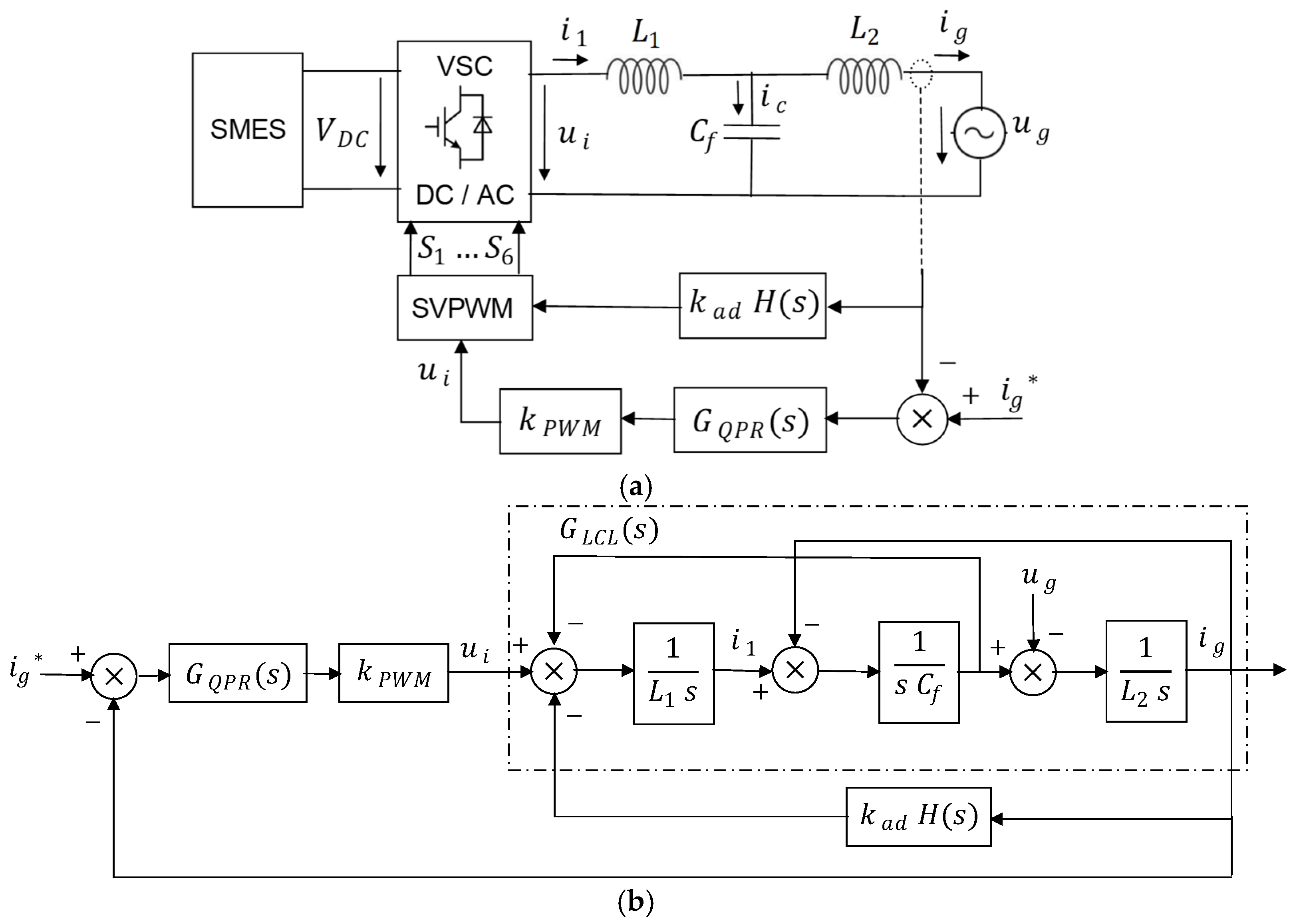
Optimized active control of voltage source controllers (VSCs) connecting SMES systems to the grid utility via LCL filter is studied in [72]. This active control method to perform the damping of the LCL resonant peak uses a multi-loop feedback control. A negative band pass filter (NBPF) on one feedback looks to suppress the resonant peak generated by the LCL mesh and another feedback looks to control the generated line current deviation. A quasi-proportional resonant (QPR) regulator is adopted for the inner loop to realize the sinusoidal current without static error. Figure 21a shows the diagram for active control of VSC with SMES connected to the grid via LCL mesh. Figure 21b shows the block diagram of VSC feedback control based on LCL virtual impedance and NBPF.
The transfer function of the NBPF is expressed by Equation (19), where  Q  is the quality factor and  ω r e s  the central resonance angular frequency.
H ( s ) = s   ω r e s / Q s 2 + s   ω r e s / Q + ω r e s 2
The transfer function of the QPR regulator is expressed in Equation (20), where  K p K R , and  ω c  are constants that enable to control of the poles’ location maximizing the damping.
G Q P R ( s ) = K p + 2   K R   ω c   s s 2 + 2   ω c   s + ω o 2
To obtain system stability, the damping feedback coefficient  k = K P W M   k a d  and quality factor  Q  should satisfy the relationship (21).
0 < k < L 1 + L 2   Q   ω r e s
The synchronous reference frame (SRF) theory [90,91], is used to perform the determination of the harmonic content. Figure 22 shows the basic system that determines the harmonic content based on the SRF theory.
The three-phase current components  I a b c  from the grid are converted into quadrature components  I α β  using Clarke’s transformation and then into  I d q  using Park’s transformation. The quadrature components  I d q  are then filtered by a low pass filter (LPF) to remove higher harmonic content. The resulting filtered quadrature components (identified with  f  in the index) are again converted by the inverse Park and Clarke transformations into final three-phase current components without harmonic content. These last ones are subtracted from the initial three-phase current components to find the harmonic content in each phase. The obtained harmonic content is used for the cancellation of harmonic by active filters.
An active harmonics filter by appropriate control of a VSC and DC-chopper connecting an SMES to the grid was analyzed and simulated [92]. A PI with HCC was adopted for the VSC control to follow the reference line voltage and current. The two switches of the DC chopper are controlled by a comparator of the DC-link voltage with the reference voltage value.
As described in the previous Section 6.1.2, the two SMES systems that execute power fluctuation suppression in PV generation perform also active current harmonics filtering.

8.2. Active Harmonics Filtering Challenges

With respect to the active harmonics filtering challenges will be on the:
(1)
Determination of the minimum optimum SMES energy storage capacity that is necessary to generate cancellation currents equal in magnitude but opposite in phase to the detected harmonics.
(2)
Development of VSC control systems based simultaneously on the SRF theory presented in Figure 21 to perform active harmonics filtering [90,91], and on the multiloop VSC feedback control with LCL virtual impedance and NBPF shown in Figure 21b to prevent LCL filter resonance [72].

9. Quantitative Overview

Each SMES system is defined by current converters and types of control used. Some SMES systems to suppress fluctuations from DFIG act also as fault current limiters to avoid the LVRT effect during periods when the grid voltage reduces significantly during the occurrence of short-circuit faults. Also, some SMES systems to suppress fluctuations from PV power generation also perform active harmonic filtering.
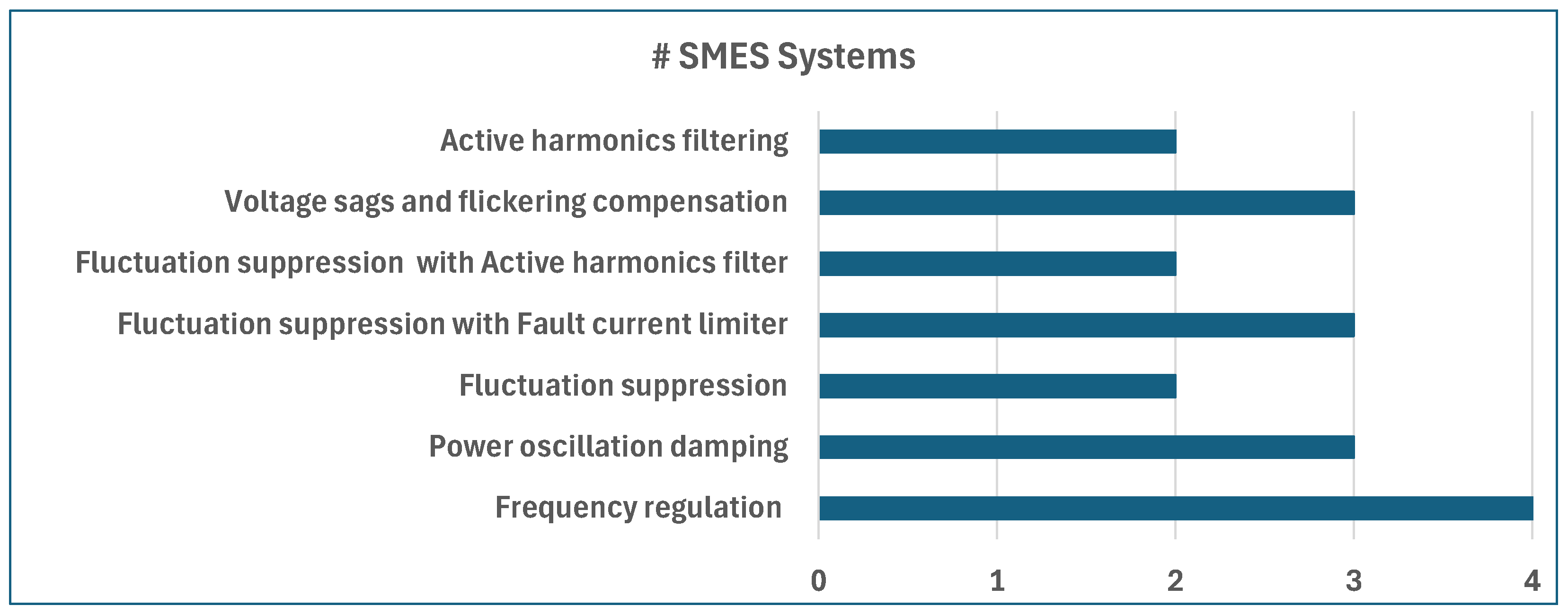
Figure 23 presents a graphic of the number of identified systems for each class of power quality regulation service. The systems for only fluctuation suppression and the ones with fault current limiter or active current harmonics were considered in different classes.
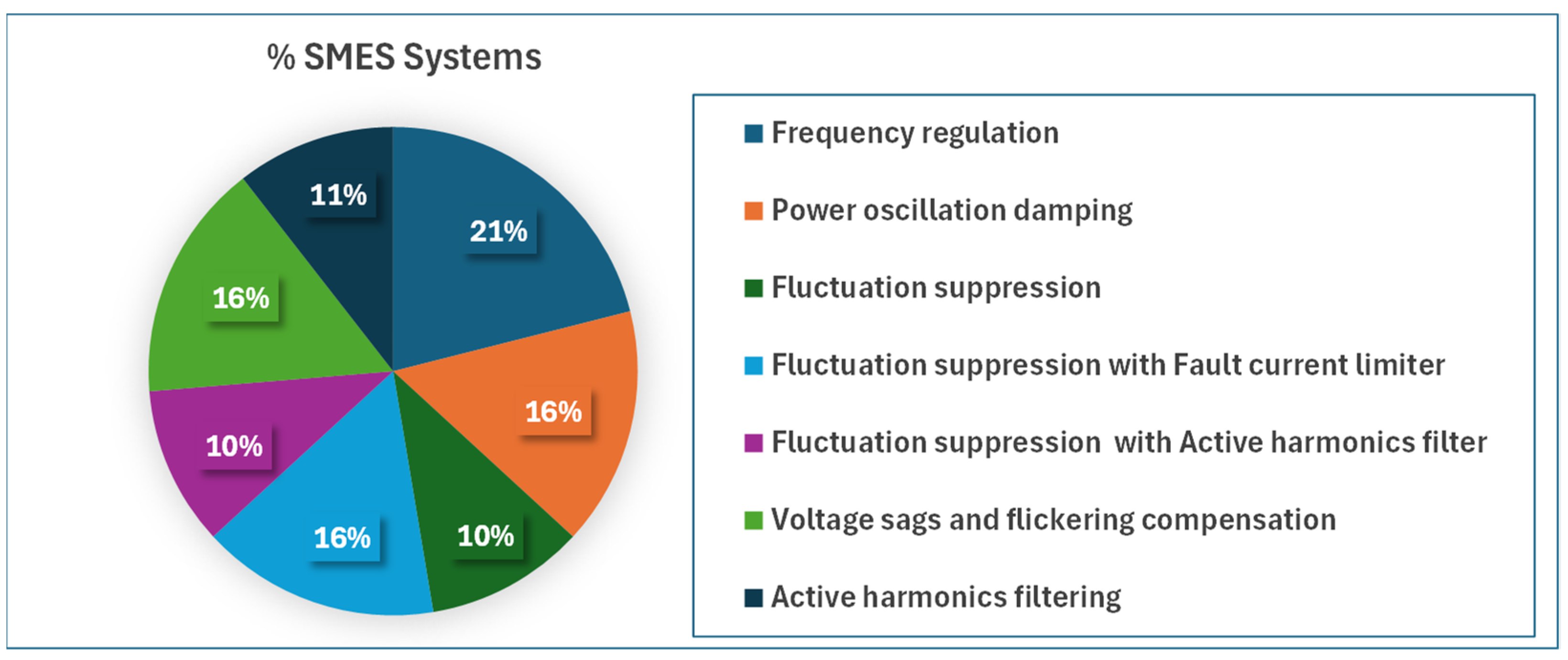
Figure 24 presents a pie chart with the percentage of identified systems for each class of power quality regulation service.
The percentage of identified SMES systems that perform power fluctuation suppression is about  50 % , power oscillation damping  19 % , and frequency regulation  25 % . Special attention has been paid to suppressing the power fluctuations created by the intermittency of decentralized energy renewable resources, especially from wind and photovoltaic generation.

10. Conclusions

Superconducting magnetic energy storage (SMES) systems can charge, present high-rated powers, high efficiencies, and very short charge and discharge periods of a few seconds. Because of their ability to perform a fast high active power compensation, their applicability is more suited to power quality control and regulation purposes. Studies have also shown the potential economic viability of SMES systems for grid applications.
As a result of this research, several SMES systems for power quality control and regulation services were identified and classified. This classification was performed concerning the type of power quality control and regulation service, point of connection, power current converters used, and the control strategies adopted.
Different models of SMES systems for frequency regulation purposes were identified to enable modeling the contribution of these systems in an overall frequency regulation system. These include models of SMES systems as a second-order lead-lag compensator or as a fractional order proportional integral (FOPI) controller.
The connection or disconnection of decentralized renewable power generation plants with inverters, to or from the grid, is characterized by a different dynamic from that of traditional synchronous generators (SG). Adaptative SMES systems have also been proposed to track the different power oscillation dynamics that result from the connection or disconnection of different power generation systems. Distributed control SMES systems using fuzzy logic control to account for the influence of other non-local generators on power oscillations were also proposed.
Power generation from distributed energy resources (DER) based on renewable resources is intermittent, creating power fluctuation in the grid. Special attention has been paid recently to proposing SMES systems for power fluctuation suppression. Several SMES systems have been proposed to suppress the power fluctuation from wind energy conversion systems (WECS) and photovoltaic (PV) systems. Some SMES fluctuation suppression systems were designed specifically for double-fed induction generators (DFIG). These include an extra fault current limiting capability to avoid DFIG in continuing injecting power during short-circuit faults when the grid voltage is low, due to their low voltage ride-through (LVRT) capability. Others include active harmonic filtering to mitigate the total harmonic distortion from inverters.
This document identifies SMES system solutions for power quality control and regulation services within grids with increasing instability due to the even greater integration of power generation from DER based on renewable resources.

Author Contributions

Conceptualization, A.J.A.C. and H.M.; methodology, A.J.A.C. and H.M.; software, A.J.A.C. and H.M.; validation, A.J.A.C. and H.M.; formal analysis, A.J.A.C. and H.M.; investigation, A.J.A.C. and H.M.; resources, H.M.; data curation, A.J.A.C. and H.M.; writing—original draft preparation, A.J.A.C.; writing—review and editing, A.J.A.C. and H.M.; visualization, A.J.A.C. and H.M.; supervision, H.M.; project administration, H.M.; funding acquisition, H.M. All authors have read and agreed to the published version of the manuscript.

Funding

This research was funded by project C644914747-00000023/56—“Aliança para a Transição Energética”, financed by the Recovery and Resilience Plan (RRP)—Component 5: “Agendas Mobilizadoras para a Inovação Empresarial”, included in the Next Generation EU funding program.

Data Availability Statement

The original contributions presented in the study are included in the article, further inquiries can be directed to the corresponding author.

Acknowledgments

The authors acknowledge the support given by the laboratories from the electrical engineering department of IST-UL.

Conflicts of Interest

The authors declare no conflicts of interest.

References

  1. Hjalmarsson, J.; Thomas, K.; Boström, C. Service stacking using energy storage systems for grid applications—A review. J. Energy Storage 2023, 60, 106639. [Google Scholar] [CrossRef]
  2. Luo, X.; Wang, J.; Dooner, M.; Clarke, J. Overview of current development in electrical energy storage technologies and the application potential in power system operation. Appl. Energy 2015, 137, 511–536. [Google Scholar] [CrossRef]
  3. Luongo, C.A.; Baldwin, T.; Ribeiro, P.; Weber, C.M. A 100 MJ SMES demonstration at FSU-CAPS. IEEE Trans. Appl. Supercond. 2003, 13, 1800–1805. [Google Scholar] [CrossRef]
  4. Sparacio, S.; Napolitano, A.; Savoldi, L.; Viarengo, S.; Laviano, F. Design of a Module for a 10 MJ Toroidal YBCO Superconducting Magnetic Energy Storage. IEEE Trans. Appl. Supercond. 2022, 32, 5700105. [Google Scholar] [CrossRef]
  5. Zhao, Z.; Wang, Y.; Gao, Y.; Yang, Z.; Li, Z.; Pi, W. Mechanical characterization of a 10-MJ HTS SMES magnet wound by quasi-isotropic strands and directly stacked tape conductors. Superconductivity 2023, 5, 100042. [Google Scholar] [CrossRef]
  6. Katagiri, T.; Nakabayashi, H.; Nijo, Y.; Tamada, T.; Noda, T.; Hirano, N.; Nagata, T.; Nagaya, S.; Yamane, M.; Ishii, Y.; et al. Field Test Result of 10MVA/20MJ SMES for Load Fluctuation Compensation. IEEE Trans. Appl. Supercond. 2009, 19, 1993–1998. [Google Scholar] [CrossRef]
  7. Singh, H.; Vadhera, S. Comparative analysis between SMES and BESS in application of VSC-HVDC system. In Proceedings of the 2015 Annual IEEE India Conference (INDICON), New Delhi, India, 17–20 December 2015; pp. 1–6. [Google Scholar]
  8. Adetokun, B.B.; Oghorada, O.; Abubakar, S.J. Superconducting magnetic energy storage systems: Prospects and challenges for renewable energy applications. J. Energy Storage 2022, 55, 105663. [Google Scholar] [CrossRef]
  9. Molina-Ibáñez, E.-L.; Rosales-Asensio, E.; Pérez-Molina, C.; Pérez, F.M.; Colmenar-Santos, A. Analysis on the electric vehicle with a hybrid storage system and the use of Superconducting magnetic energy storage (SMES). Energy Rep. 2021, 7, 854–873. [Google Scholar] [CrossRef]
  10. Kebede, A.A.; Kalogiannis, T.; Van Mierlo, J.; Berecibar, M. A comprehensive review of stationary energy storage devices for large scale renewable energy sources grid integration. Renew. Sustain. Energy Rev. 2022, 159, 112213. [Google Scholar] [CrossRef]
  11. Huang, Y.; Ru, Y.; Shen, Y.; Zeng, Z. Characteristics and Applications of Superconducting Magnetic Energy Storage. J. Phys. Conf. Ser. 2021, 2108, 012038. [Google Scholar] [CrossRef]
  12. Jin, J.X.; Chen, X.Y. Study on the SMES Application Solutions for Smart Grid. Phys. Procedia 2012, 36, 902–907. [Google Scholar] [CrossRef]
  13. Alkhafaji, A.S.; Trabelsi, H. Uses of Superconducting Magnetic Energy Storage Systems in Microgrids under Unbalanced Inductive Loads and Partial Shading Conditions. Energies 2022, 15, 8597. [Google Scholar] [CrossRef]
  14. Yunus, A.M.S.; Saini, M. Overview of SMES units application on smart grid systems. In Proceedings of the 2016 International Seminar on Intelligent Technology and Its Applications (ISITIA), Lombok, Indonesia, 28–30 July 2016; pp. 465–470. [Google Scholar]
  15. Jacques, B.J.; Armel, T.K.F.; Astrid, M.N.B.; René, T. Contribution to the improvement of the performances of PV/wind microgrids integrating a hybrid SMES/battery energy storage unit. J. Energy Storage 2024, 85, 111011. [Google Scholar] [CrossRef]
  16. Wang, P.; Lu, J.; Wu, Y.; Xu, L.; Li, J.; Mao, H.; Tian, Y.; Xu, B.; Huang, J. A Novel Cooperative Control for SMES/Battery Hybrid Energy Storage in PV Grid-Connected System. IEEE Trans. Appl. Supercond. 2024, 34, 5401605. [Google Scholar] [CrossRef]
  17. Papageorgiou, P.G.; Papafilippou, P.T.; Oureilidis, K.O.; Christoforidis, G.C. An Adaptive Controller of a Hybrid Storage System for Power Smoothing with Enlarged Battery Lifetime. IEEE Trans. Sustain. Energy 2024, 15, 2567–2580. [Google Scholar] [CrossRef]
  18. Hernando, C.; Munilla, J.; García-Tabarés, L.; Pedraz, G. Optimization of High Power SMES for Naval Applications. IEEE Trans. Appl. Supercond. 2023, 33, 5700205. [Google Scholar] [CrossRef]
  19. Jin, J.X.; Xu, W.; Chen, X.Y.; Zhou, X.; Zhang, J.Y.; Gong, W.Z.; Ren, A.L.; Xin, Y. Developments of SMES devices and potential applications in smart grids. In Proceedings of the IEEE PES Innovative Smart Grid Technologies, Washington, DC, USA, 16–20 January 2012; pp. 1–6. [Google Scholar]
  20. Bevrani, H.; Golpîra, H.; Messina, A.R.; Hatziargyriou, N.; Milano, F.; Ise, T. Power system frequency control: An updated review of current solutions and new challenges. Electr. Power Syst. Res. 2021, 194, 107114. [Google Scholar] [CrossRef]
  21. Khan, I.A.; Mokhlis, H.; Mansor, N.N.; Illias, H.A.; Awalin, L.J.; Wang, L. New trends and future directions in load frequency control and flexible power system: A comprehensive review. Alex. Eng. J. 2023, 71, 263–308. [Google Scholar] [CrossRef]
  22. Filippidis, S.; Bouhouras, A.; Poulakis, N.; Christoforidis, G. A Review of the Cryocooler-Based Cooling Systems for SMES. IEEE Trans. Appl. Supercond. 2021, 31, 4902713. [Google Scholar] [CrossRef]
  23. Zhang, H.; Nie, Z.; Xiao, X.; Aggarwal, R.; Kang, Q.; Ainslie, M.; Zhu, J.; Coombs, T.; Yuan, W. Design and Simulation of SMES System Using YBCO Tapes for Direct Drive Wave Energy Converters. IEEE Trans. Appl. Supercond. 2013, 23, 5700704. [Google Scholar] [CrossRef]
  24. Zimmermann, A.W.; Sharkh, S.M. Design of a 1 MJ/100 kW high temperature superconducting magnet for energy storage. Energy Rep. 2020, 6, 180–188. [Google Scholar] [CrossRef]
  25. Wang, Q.; Dai, Y.; Song, S.; Wen, H.; Bai, Y.; Yan, L.; Kim, K. A 30 kJ Bi2223 High Temperature Superconducting Magnet for SMES with Solid-Nitrogen Protection. IEEE Trans. Appl. Supercond. 2008, 18, 754–757. [Google Scholar] [CrossRef]
  26. Atomura, N.; Takahashi, T.; Amata, H.; Iwasaki, T.; Son, K.; Miyagi, D.; Tsuda, M.; Hamajima, T.; Shintomi, T.; Makida, Y.; et al. Conceptual design of MgB2 coil for the 100 MJ SMES of advanced superconducting power conditioning system (ASPCS). Phys. Procedia 2012, 27, 400–403. [Google Scholar] [CrossRef]
  27. Lee, S.; Park, S.-H.; Kim, W.-S.; Lee, J.-K.; Lee, S.; Park, C.; Bae, J.-H.; Kim, S.-H.; Seong, K.-C.; Choi, K.; et al. Analysis of Eddy Current Losses and Magnetization Losses in Toroidal Magnets for a 2.5 MJ HTS SMES. IEEE Trans. Appl. Supercond. 2011, 21, 1354–1357. [Google Scholar] [CrossRef]
  28. Kim, K.; Kim, A.-R.; Kim, J.-G.; Park, M.; Yu, I.-K.; Sohn, M.-H.; Eom, B.-Y.; Sim, K.; Kim, S.; Kim, H.-J.; et al. Analysis of Operational Loss Characteristics of 10 kJ Class Toroid-Type SMES. IEEE Trans. Appl. Supercond. 2011, 21, 1340–1343. [Google Scholar] [CrossRef]
  29. Kim, A.-R.; Kim, G.-H.; Kim, K.-M.; Kim, J.-G.; Kim, D.-W.; Park, M.; Yu, I.-K.; Kim, S.-H.; Sim, K.; Seong, K.-C. Design and Manufacturing of a SMES Model Coil for Real Time Digital Simulator Based Power Quality Enhancement Simulation. IEEE Trans. Appl. Supercond. 2010, 20, 1339–1343. [Google Scholar] [CrossRef]
  30. Trillaud, F.; Cruz, L.S. Conceptual Design of a 200-kJ 2G-HTS Solenoidal μ-SMES. IEEE Trans. Appl. Supercond. 2014, 24, 5700205. [Google Scholar] [CrossRef]
  31. Kamada, H.; Ninomiya, A.; Nomura, S.; Yagai, T.; Nakamura, T.; Chikaraishi, H. Development of 1-T Class Force-Balanced Helical Coils Using REBCO Tapes. IEEE Trans. Appl. Supercond. 2020, 30, 4600905. [Google Scholar] [CrossRef]
  32. Kimura, Y.; Kamada, H.; Nomura, S.; Yagai, T.; Nakamura, T.; Tsutsui, H.; Chikaraishi, H.; Yanagi, N.; Imagawa, S. Development of a Prototype Winding Machine for Helical Coils Using High-Temperature Superconducting Tapes. IEEE Trans. Appl. Supercond. 2016, 26, 4202104. [Google Scholar] [CrossRef]
  33. Kim, A.-R.; Jung, H.-Y.; Kim, J.-H.; Park, M.; Yu, I.-K.; Kim, S.-H.; Sim, K.; Kim, H.-J.; Seong, K.-C. Design of a 10 kJ Class SMES Model Coil for Real Time Digital Simulator Based Grid Connection Study. IEEE Trans. Appl. Supercond. 2009, 19, 2023–2027. [Google Scholar] [CrossRef]
  34. Wang, Q.; Song, S.; Lei, Y.; Dai, Y.; Zhang, B.; Wang, C.; Lee, S.; Kim, K. Design and Fabrication of a Conduction-Cooled High Temperature Superconducting Magnet for 10 kJ Superconducting Magnetic Energy Storage System. IEEE Trans. Appl. Supercond. 2006, 16, 570–573. [Google Scholar] [CrossRef]
  35. Zheng, Z.-X.; Chen, X.-Y.; Xiao, X.-Y.; Huang, C.-J. Design and Evaluation of a Mini-Size SMES Magnet for Hybrid Energy Storage Application in a kW-Class Dynamic Voltage Restorer. IEEE Trans. Appl. Supercond. 2017, 27, 5700911. [Google Scholar] [CrossRef]
  36. Jubleanu, R.; Cazacu, D. Design and Numerical Study of Magnetic Energy Storage in Toroidal Superconducting Magnets Made of YBCO and BSCCO. Magnetochemistry 2023, 9, 216. [Google Scholar] [CrossRef]
  37. Vialle, J.; Badel, A.; Tixador, P.; Ciceron, J.; Forest, F.; Pasquet, R. Preliminary Tests of Pancakes From a 12 T REBCO Insulated Solenoid Magnet. IEEE Trans. Appl. Supercond. 2021, 31, 4600805. [Google Scholar] [CrossRef]
  38. Kim, H.J.; Seong, K.C.; Cho, J.W.; Bae, J.H.; Sim, K.D.; Kim, S.; Lee, E.Y.; Ryu, K.; Kim, S.H. 3 MJ/750 kVA SMES System for Improving Power Quality. IEEE Trans. Appl. Supercond. 2006, 16, 574–577. [Google Scholar] [CrossRef]
  39. Nomura, S.; Kasuya, K.; Tanaka, N.; Tsuboi, K.; Tsutsui, H.; Tsuji-Iio, S.; Shimada, R. Experimental Results of a 7-T Force-Balanced Helical Coil for Large-Scale SMES. IEEE Trans. Appl. Supercond. 2008, 18, 701–704. [Google Scholar] [CrossRef]
  40. Nomura, S.; Kasuya, K.; Tanaka, N.; Tsuboi, K.; Tsutsui, H.; Tsuji-Iio, S.; Shimada, R.; Arai, K.; Ninomiya, A.; Ishigohka, T. Quench Properties of a 7-T Force-Balanced Helical Coil for Large-Scale SMES. IEEE Trans. Appl. Supercond. 2009, 19, 2004–2007. [Google Scholar] [CrossRef]
  41. Hayashi, H.; Hatabe, Y.; Nagafuchi, T.; Taguchi, A.; Terazono, K.; Ishii, T.; Taniguchi, S. Test Results of Power System Control by Experimental SMES. IEEE Trans. Appl. Supercond. 2006, 16, 598–601. [Google Scholar] [CrossRef]
  42. Ali, M.H.; Wu, B.; Dougal, R.A. An Overview of SMES Applications in Power and Energy Systems. IEEE Trans. Sustain. Energy 2010, 1, 38–47. [Google Scholar] [CrossRef]
  43. Sun, Q.; Lv, H.; Gao, S.; Wei, K.; Mauersberger, M. Optimized Control of Reversible VSC with Stability Mechanism Study in SMES Based V2G System. IEEE Trans. Appl. Supercond. 2019, 29, 5401106. [Google Scholar] [CrossRef]
  44. Chen, X.; Xie, Q.; Bian, X.; Shen, B. Energy-saving superconducting magnetic energy storage (SMES) based interline DC dynamic voltage restorer. J. Power Energy Syst. 2022, 8, 238–248. [Google Scholar] [CrossRef]
  45. Jin, J.X.; Wang, J.; Yang, R.H.; Zhang, T.L.; Mu, S.; Fan, Y.J.; Xing, Y.Q. A superconducting magnetic energy storage with dual functions of active filtering and power fluctuation suppression for photovoltaic microgrid. J. Energy Storage 2021, 38, 102508. [Google Scholar] [CrossRef]
  46. Zhu, J.; Bao, X.; Yang, B.; Chen, P.; Yang, Y.; Qiu, M. Dynamic Simulation Test Research on Power Fluctuation Compensation Using Hybrid SMES of YBCO and BSCCO Tapes. IEEE Trans. Appl. Supercond. 2012, 22, 5700404. [Google Scholar] [CrossRef]
  47. Abdalrahman, G.; Abdalla, O.H.; Jibril, M.I.; Awad, A.A. Space Vector Pulse Width Modulation Technique Applied to Two Level Voltage Source Inverter. SUST J. Eng. Comput. Sci. 2018, 19, 10–17. [Google Scholar]
  48. Shen, Y.; Zheng, Z.; Wang, Q.; Liu, P.; Yang, X. DC Bus Current Sensed Space Vector Pulsewidth Modulation for Three-Phase Inverter. IEEE Trans. Transp. Electrif. 2021, 7, 815–824. [Google Scholar] [CrossRef]
  49. Abraham, R.J.; Das, D.; Patra, A. Automatic generation control of an interconnected hydrothermal power system considering superconducting magnetic energy storage. Int. J. Electr. Power Energy Syst. 2007, 29, 571–579. [Google Scholar] [CrossRef]
  50. Elmelegi, A.; Mohamed, E.A.; Aly, M.; Ahmed, E.M.; Mohamed, A.-A.A.; Elbaksawi, O. Optimized Tilt Fractional Order Cooperative Controllers for Preserving Frequency Stability in Renewable Energy-Based Power Systems. IEEE Access 2021, 9, 8261–8277. [Google Scholar] [CrossRef]
  51. Pappachen, A.; Fathima, A.P. Load frequency control in deregulated power system integrated with SMES–TCPS combination using ANFIS controller. Int. J. Electr. Power Energy Syst. 2016, 82, 519–534. [Google Scholar] [CrossRef]
  52. Magdy, G.; Bakeer, A.; Alhasheem, M. Superconducting energy storage technology-based synthetic inertia system control to enhance frequency dynamic performance in microgrids with high renewable penetration. Prot. Control Mod. Power Syst. 2021, 6, 36. [Google Scholar] [CrossRef]
  53. Bhatt, P.; Ghoshal, S.P.; Roy, R. Coordinated control of TCPS and SMES for frequency regulation of interconnected restructured power systems with dynamic participation from DFIG based wind farm. Renew. Energy 2012, 40, 40–50. [Google Scholar] [CrossRef]
  54. Colmenar-Santos, A.; Molina-Ibáñez, E.-L.; Rosales-Asensio, E.; Blanes-Peiró, J.-J. Legislative and economic aspects for the inclusion of energy reserve by a superconducting magnetic energy storage: Application to the case of the Spanish electrical system. Renew. Sustain. Energy Rev. 2018, 82, 2455–2470. [Google Scholar] [CrossRef]
  55. Soman, R.; Ravindra, H.; Huang, X.; Schoder, K.; Steurer, M.; Yuan, W.; Zhang, M.; Venuturumilli, S.; Chen, X. Preliminary Investigation on Economic Aspects of Superconducting Magnetic Energy Storage (SMES) Systems and High-Temperature Superconducting (HTS) Transformers. IEEE Trans. Appl. Supercond. 2018, 28, 5400805. [Google Scholar] [CrossRef]
  56. European Union. Commission Regulation (EU) 2017/1485 of 2 August 2017 Establishing a Guideline on Electricity Transmission System Operation; European Union: Brussels, Belgium, 2017. [Google Scholar]
  57. Mohamed, E.A.; Ahmed, E.M.; Elmelegi, A.; Aly, M.; Elbaksawi, O.; Mohamed, A.-A.A. An Optimized Hybrid Fractional Order Controller for Frequency Regulation in Multi-Area Power Systems. IEEE Access 2020, 8, 213899–213915. [Google Scholar] [CrossRef]
  58. Banerjee, S.; Chatterjee, J.K.; Tripathy, S.C. Application of magnetic energy storage unit as load-frequency stabilizer. IEEE Trans. Energy Convers. 1990, 5, 46–51. [Google Scholar] [CrossRef]
  59. Chandrakala, V.; Sukumar, B.; Sankaranarayanan, K. Load Frequency Control of Multi-source Multi-area Hydro Thermal System Using Flexible Alternating Current Transmission System Devices. Electr. Power Compon. Syst. 2014, 42, 927–934. [Google Scholar] [CrossRef]
  60. Vyshna, K.; Thresia, M.M.; Shahin, M. Design of SMES for Load Frequency Control in Power Systems with Renewable Integration. In Proceedings of the 2023 5th International Conference on Energy, Power and Environment: Towards Flexible Green Energy Technologies (ICEPE), Shillong, India, 15–17 June 2023; pp. 1–6. [Google Scholar]
  61. Khan, I.A.; Mokhlis, H.; Mansor, N.N.; Illias, H.A.; Usama, M.; Daraz, A.; Wang, L.; Awalin, L.J. Load Frequency Control Using Golden Eagle Optimization for Multi-Area Power System Connected Through AC/HVDC Transmission and Supported with Hybrid Energy Storage Devices. IEEE Access 2023, 11, 44672–44695. [Google Scholar] [CrossRef]
  62. Ali, H.H.; Kassem, A.M.; Al-Dhaifallah, M.; Fathy, A. Multi-Verse Optimizer for Model Predictive Load Frequency Control of Hybrid Multi-Interconnected Plants Comprising Renewable Energy. IEEE Access 2020, 8, 114623–114642. [Google Scholar] [CrossRef]
  63. Pati, S.S.; Subudhi, U. Frequency regulation of Solar-Wind integrated multi-area system with SMES and SSSC. In Proceedings of the 2021 IEEE International Power and Renewable Energy Conference (IPRECON), Kerala, India, 24–26 September 2021; pp. 1–4. [Google Scholar]
  64. Alam, M.S.; Al-Ismail, F.S.; Abido, M.A. PV/Wind-Integrated Low-Inertia System Frequency Control: PSO-Optimized Fractional-Order PI-Based SMES Approach. Sustainability 2021, 13, 7622. [Google Scholar] [CrossRef]
  65. Tripathy, S.C.; Juengst, K.P. Sampled data automatic generation control with superconducting magnetic energy storage in power systems. IEEE Trans. Energy Convers. 1997, 12, 187–192. [Google Scholar] [CrossRef]
  66. Tran, X.K.; Chen, Y.; Phan, G.T.; Huynh, D.H. Optimal Design for Frequency Fluctuation Control System with SMES Unit. In Proceedings of the 2020 4th International Conference on Robotics and Automation Sciences (ICRAS), Chengdu, China, 14–16 June 2020; pp. 50–54. [Google Scholar]
  67. Li, T.; Xie, J.; Gong, X.; Chen, M.; Zeng, Q.; Chen, X. Mechanism Analysis and Controller Design of SMES-Based Power Oscillation Damping. IEEE Trans. Appl. Supercond. 2021, 31, 5403704. [Google Scholar] [CrossRef]
  68. Li, T.; Hu, W.; Zhang, B.; Zhang, G.; Zhang, Z.; Chen, Z. SMES Damping Controller Design and Real-Time Parameters Tuning for Low-Frequency Oscillation. IEEE Trans. Appl. Supercond. 2021, 31, 3800604. [Google Scholar] [CrossRef]
  69. Tang, Y.; Mu, C.; He, H. SMES-Based Damping Controller Design Using Fuzzy-GrHDP Considering Transmission Delay. IEEE Trans. Appl. Supercond. 2016, 26, 5701206. [Google Scholar] [CrossRef]
  70. Zhou, X.; Sun, H.; Jiang, L.; Zeng, P. A SMES-based adaptive damping controller design in wind power system. In Proceedings of the 2016 IEEE 8th International Power Electronics and Motion Control Conference (IPEMC-ECCE Asia), Hefei, China, 22–26 May 2016; pp. 212–216. [Google Scholar]
  71. Rai, D.; Gokaraju, R.; Faried, S.O. Adaptive Control Using Constrained RLS and Dynamic Pole-Shift Technique for TCSCs. IEEE Trans. Power Deliv. 2014, 29, 224–234. [Google Scholar] [CrossRef]
  72. Sun, Q.; Miao, Y.; Zhao, L.; Xu, J.; Gao, S.; Wei, K.; Wang, L. Study on LCL-Type Grid-Connected VSC Based on Optimized Active Damping with NBPF for SMES System. IEEE Trans. Appl. Supercond. 2024, 34, 5701505. [Google Scholar] [CrossRef]
  73. dos Santos Costa, A.J.A.; Valério, D.; da Costa Branco, P.J. Predictive control model to manage power flow on a hybrid wind-photovoltaic and diesel microgeneration power plant with additional storage capacity. IET Cyber-Phys. Syst. Theory Appl. 2018, 3, 206–211. [Google Scholar] [CrossRef]
  74. Amezquita, H.; Carvalho, P.M.S.; Morais, H. Wind Forecast at Medium Voltage Distribution Networks. Energies 2023, 16, 2887. [Google Scholar] [CrossRef]
  75. Amezquita, H.; Guzman, C.P.; Morais, H. Forecasting Electric Vehicles’ Charging Behavior at Charging Stations: A Data Science-Based Approach. Energies 2024, 17, 3396. [Google Scholar] [CrossRef]
  76. Zhang, W.; Zhang, D.; Mu, B.; Wang, L.Y.; Bao, Y.; Jiang, J.; Morais, H. Decentralized Electric Vehicle Charging Strategies for Reduced Load Variation and Guaranteed Charge Completion in Regional Distribution Grids. Energies 2017, 10, 147. [Google Scholar] [CrossRef]
  77. Yunus, A.M.S.; Abu-Siada, A.; Mosaad, M.I.; Albalawi, H.; Aljohani, M.; Jin, J.X. Application of SMES Technology in Improving the Performance of a DFIG-WECS Connected to a Weak Grid. IEEE Access 2021, 9, 124541–124548. [Google Scholar] [CrossRef]
  78. Salama, H.S.; Vokony, I. Voltage and Frequency Control of Balanced/Unbalanced Distribution System Using the SMES System in the Presence of Wind Energy. Electricity 2021, 2, 205–224. [Google Scholar] [CrossRef]
  79. Ngamroo, I.; Karaipoom, T. Cooperative Control of SFCL and SMES for Enhancing Fault Ride Through Capability and Smoothing Power Fluctuation of DFIG Wind Farm. IEEE Trans. Appl. Supercond. 2014, 24, 5400304. [Google Scholar] [CrossRef]
  80. Ngamroo, I.; Karaipoom, T. Improving Low-Voltage Ride-Through Performance and Alleviating Power Fluctuation of DFIG Wind Turbine in DC Microgrid by Optimal SMES with Fault Current Limiting Function. IEEE Trans. Appl. Supercond. 2014, 24, 5700805. [Google Scholar] [CrossRef]
  81. Karaipoom, T.; Ngamroo, I. Optimal Superconducting Coil Integrated into DFIG Wind Turbine for Fault Ride Through Capability Enhancement and Output Power Fluctuation Suppression. IEEE Trans. Sustain. Energy 2015, 6, 28–42. [Google Scholar] [CrossRef]
  82. Jin, J.X.; Yang, R.H.; Zhang, R.T.; Fan, Y.J.; Xie, Q.; Chen, X.Y. Combined low voltage ride through and power smoothing control for DFIG/PMSG hybrid wind energy conversion system employing a SMES-based AC-DC unified power quality conditioner. Int. J. Electr. Power Energy Syst. 2021, 128, 106733. [Google Scholar] [CrossRef]
  83. Shivashankar, S.; Mekhilef, S.; Mokhlis, H.; Karimi, M. Mitigating methods of power fluctuation of photovoltaic (PV) sources—A review. Renew. Sustain. Energy Rev. 2016, 59, 1170–1184. [Google Scholar] [CrossRef]
  84. Wang, J.; Mu, S.; Zhou, Q.; Li, Y.J.; Zhang, T.L. Design and Performance Analysis of PV-SMES-Based Microgrid Integrated with Power Fluctuation Suppression and Active Filtering Control. IEEE Trans. Appl. Supercond. 2021, 31, 5402705. [Google Scholar] [CrossRef]
  85. Masetti, C. Revision of European Standard EN 50160 on power quality: Reasons and solutions. In Proceedings of the 14th International Conference on Harmonics and Quality of Power—ICHQP 2010, Bergamo, Italy, 26–29 September 2010; pp. 1–7. [Google Scholar]
  86. Jiang, X.; Zhu, X.; Cheng, Z.; Ren, X.; He, Y. A 150 kVA/0.3 MJ SMES voltage sag compensation system. IEEE Trans. Appl. Supercond. 2005, 15, 1903–1906. [Google Scholar] [CrossRef]
  87. Zheng, Z.X.; Xiao, X.Y.; Li, C.S.; Chen, Z.; Zhang, Y. Performance Evaluation of SMES System for Initial and Steady Voltage Sag Compensations. IEEE Trans. Appl. Supercond. 2016, 26, 5701105. [Google Scholar] [CrossRef]
  88. Yunus, A.M.S.; Habriansyah, I.; Abu-Siada, A.; Masoum, M.A.S. Sag and Flicker Reduction Using Hysteresis-Fuzzy Control-Based SMES Unit. Can. J. Electr. Comput. Eng. 2019, 42, 52–57. [Google Scholar] [CrossRef]
  89. IEEE Std 519-2014; IEEE Recommended Practice and Requirements for Harmonic Control in Electric Power Systems. IEEE: Piscataway, NJ, USA, 2014. [CrossRef]
  90. Tong, L.; Qian, Z.; Kuang, N.; Lingxiao, X.; Peng, F.Z. Optimal Design of Synchronous Reference Frame Harmonic Detection Method. In Proceedings of the 2007 IEEE Power Electronics Specialists Conference, Orlando, FL, USA, 17–21 June 2007; pp. 1071–1076. [Google Scholar]
  91. Wang, X.; Liu, J.; Hu, J.; Meng, Y.; Yuan, C. Frequency characteristics of the d-q synchronous-frame current reference generation methods for active power filter. In Proceedings of the 2007 7th International Conference on Power Electronics, Daegu, Republic of Korea, 22–26 October 2007; pp. 945–950. [Google Scholar]
  92. Simoesõ, F.; Pires, V.F.; Murta-Pina, J. Assessment of Using Superconducting Magnetic Energy Storage for Current Harmonic Compensation. In Proceedings of the 2020 International Young Engineers Forum (YEF-ECE), Costa da Caparica, Portugal, 3 July 2020; pp. 73–77. [Google Scholar]
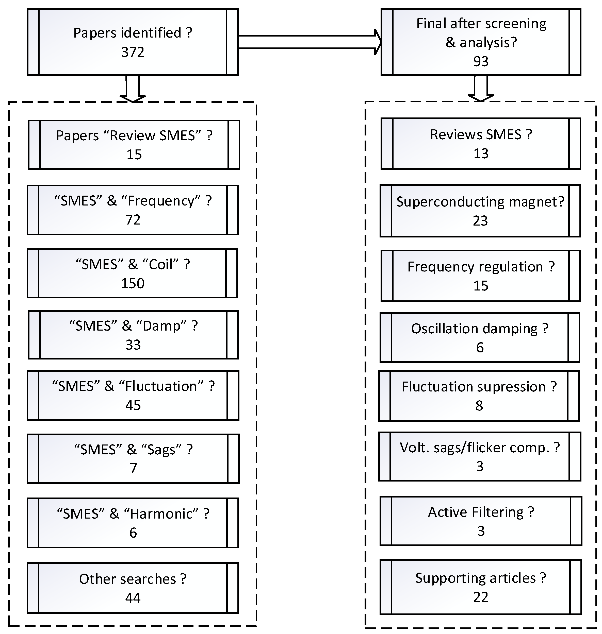
Figure 1. Searches and final references from the adopted systematic review methodology.
Energies 17 06028 g001
Figure 2. Set with a VSC and DC chopper to control the active power flow to and from an SMES.
Energies 17 06028 g002
Figure 3. State input variables and reference values in the DSP control of the VSC and DC chopper.
Energies 17 06028 g003
Figure 4. System to compute components  V α  and  V β  that generate the SVPWM to control the VSC.
Energies 17 06028 g004
Figure 5. The system to compute the duty cycle  D  for controlling DC-chopper switches  S 1  and  S 2 .
Energies 17 06028 g005
Figure 6. Bidirectional CSC used to interface the SMES coil with the AC grid.
Energies 17 06028 g006
Figure 7. Alternative bidirectional converter with twelve-pulse SCR bridge and SCR bypass gate.
Energies 17 06028 g007
Figure 8. Frequency regulation system using SMES, for a grid area  i  connected to other areas  j .
Energies 17 06028 g008
Figure 9. SMES system model with two-stage lead-lag compensator.
Energies 17 06028 g009
Figure 10. SMES system model with FOPI.
Energies 17 06028 g010
Figure 11. (a) General unifilar scheme of a current source controlled SMES in the connection from an SG to the power grid; (b) system diagram of the PI-IA in the CSC.
Energies 17 06028 g011
Figure 12. Distributed control using Fuzzy-GrHDP of multiple SMES looking for the synchronous deviations between different SG in a power grid.
Energies 17 06028 g012
Figure 13. Principle (a), and Z-transform diagram (b) of the discrete adaptative control system.
Energies 17 06028 g013
Figure 14. Compensation system with fuzzy logic and HCC to suppress power fluctuation.
Energies 17 06028 g014
Figure 15. SMES connected to the AC-bus with VSC and DC chopper and cooperative SCFL.
Energies 17 06028 g015
Figure 16. Unifilar scheme of a SMES-FCL in the DC  μ -grid of DFIG.
Energies 17 06028 g016
Figure 17. Logic switching scheme for the SFCL switches  S w 1 S w 2 S 3  and  S 4 .
Energies 17 06028 g017
Figure 18. A system with the optimal SC integrated into the DC link of the DFIG wind turbine.
Energies 17 06028 g018
Figure 19. PV System with SMES interfaced with a DC chopper and VSC to the PCC.
Energies 17 06028 g019
Figure 20. PV System using SMES connected with a DC chopper to the DC link between the DC Booster and inverter.
Energies 17 06028 g020
Figure 21. (a) Diagram for active control of VSC with SMES connected via LCL mesh to the power grid; (b) block diagram of VSC feedback control based on LCL virtual impedance and NBPF.
Energies 17 06028 g021
Figure 22. A system that determines the harmonic content based on the SRF theory.
Energies 17 06028 g022
Figure 23. Graphic with the number of identified systems for each class of power quality regulation service.
Energies 17 06028 g023
Figure 24. Pie chart with the percentage identified systems for each class of power quality regulation service.
Energies 17 06028 g024
Table 1. Characteristics of superconducting magnets: geometry, coil materials, operating temperature, inductance, operating current, and energy capacity.
MagnetSuperconductor T o   [ K ] L   [ H ] I o   [ A ] E c   [ k J ] Ref.
Solenoid ,   6  double pancake coilsYBCO 4 mm tape 65 24.5 70 60 [23]
Solenoid ,   7  double pancake coilsYBCO 12 mm tape 22 11.34 450 1148 [24]
Solenoid ,   14  double pancake coilsBSCCO tape 20 2.5 155 30 [25]
Toroid ,   18  single coilsMGB2 cable 20 12.6 4 × 10 3 100 × 10 3 [26]
Toroid ,   28  double pancake coilsYBCO 12 mm tape 14 5.42 960 2.5 × 10 3 [27]
Toroid ,   30  double pancake coilsBSCCO tape 6 0.229 300 10.3 [28,29]
Solenoid ,   31  double pancake coilsYBCO 12 mm tape 65 174.7 53.8 253 [30]
Toroid, 52-layer coilsYBCO 12 mm tape 50 2.1 3 × 10 3 10 × 10 3 [4]
Toroid ,   6  helicoidal coilsYBCO 5 mm tape 4.2 2.39 × 10 3 1 × 10 3 1.2 [31,32]
Solenoid ,   7  double pancake coilsYBCO 4 mm tape 33 1.02 142 10.3 [33]
Solenoid, 13 double pancake coilsBSCCO tape 20 4.68 86 17.4 [34]
Solenoid ,   6  single coilsGDBCO wire 77 3.25 × 10 3 250 0.1 [35]
Toroid, 16 double pancake coilsBSCCO tape 77 20.24 500 2.53 × 10 3 [36]
Solenoid ,   21  double pancake coilsReBCO 12 mm tape 4.2 2.79 850 1 × 10 3 [37]
Solenoid ,   13 × 26  coilsYBCO 4 mm tape 20 144.1 × 10 3 12 × 10 3 10.1 × 10 3 [5]
Solenoid ,   64 -layer coilsNbTi wires cable 4.2 6 1 × 10 3 3 × 10 3 [38]
Solenoid ,   44  double pancake coilsNbTi/Cu strand cable 4.2 10.8 4.3 × 10 3 100 × 10 3 [3]
4  poles coil configurationNbTi wires cable 4.2 21.1 1.35 × 10 3 19.2 × 10 3 [6]
Toroid ,   3    helical coilsNbTi/Cu strand cable 4.2 1.8 552 274 [39,40]
Solenoid, 16 layers coil NbTi wires cable 4.2 0.13 6.7 × 10 3 2.9 × 10 3 [41]
Table 2. Typical values for the several model parameters in the global frequency regulation system.
ParameterValuesReferences
B i   [ p u   M W / H z ] 0.425 [49,50,51,57,58,59,60,61,62,65]
R i   [ H z / p u   M w ] 2 R i 2.7 [49,50,51,57,58,59,60,61,62,65]
T i j   [ s ] 0.054 T i j 0.087 [49,50,51,57,58,59,60,61,62,65]
T g   [ s ] 0.07 T   g 0.1 [49,50,51,52,57,58,59,60,61,62,65]
T t   [ s ] 0.3 T   t 0.4 [49,50,51,52,57,58,59,60,61,62,65]
K r   [ H z / p u   M W ] 0.33 K r 0.5 [51,62,65]
T r   [ s ] 10 [51,62,65]
T 1   [s] 41.6 T 1 48.7 [49,50,51,57,59]
T 2   [ s ] 0.513 [49,50,51,57,59]
T R   [ s ] 5 [49,50,51,57,59]
T w   [ s ] 1 [49,50,51,57,59]
K p   [ H z / p u   M W ] 100 K p 120 [49,51,58,59,61,62,65]
T p   [ s ] 15 T p 25 [49,51,58,59,61,62,65]
Table 3. Typical parameter values for wind, PV, and diesel decentralized generation systems.
WindPVDiesel
K p w 1 K p w 2 K p w 3 T p w 1   [s] T p w 2   [ s ] K P V 1 K P V 2 T P V 1   [s] T P V 1   [ s ] K d i e s
1.25 1.4 - 6 0.041 18 900 100 50 16.5
Table 4. Typical parameter values for the SMES system model with a two-stage lead-lad compensator.
K S M E S  [1] T S M E S   [ s ] T 1   [ s ] T 2   [ s ] T 3   [ s ] T 4   [ s ] Reference
2.500 0.046 0.279 0.020 0.900 0.360 [53]
0.297 0.03 0.121 0.8 0.011 0.148 [51,59]
0.2035 0.03 0.2333 0.016 0.7087 0.2481 [21,61,62,63]
Table 5. Typical parameter values for the SMES system model with FOPI.
K S M E S   [ k V / p u M W ] K i d   [ k V / k A ] T D C   [ s ] I d 0   [ k A ] L   [ H ] Reference
100 0.2 0.03 4.5 2.65 [49,51,64]
100 0.2 0.03 4.5 0.03 [50]
1 0.01 0.03 1.732 3 [52]
100 0.5 0.026 4 1 [58]
10 0.4 0.003 0.3 2.65 [65]
Table 6. Overview of scenarios for studies on frequency regulation with SMES systems.
Ref.# AreasCentralized
Generation
Decentralized
Generation
System ControlSMES InterfaceSMES System Control
[21]11: Thermal1: PV + WindSecondaryNot specifiedPI
Lead-Lag
[49]21: Thermal
2: Hydro
-Secondary 12  pulse
SCR bridge
FOPI
[50]21: Thermal
2: Hydro
1: Wind;
2: PV
SecondaryNot specifiedFOPI
[51]21: Thermal
2: Hydro
-Secondary 12  pulse
SCR bridge
FOPI
[52]11: Thermal1: PV + WindSecondary 12  pulse
SCR bridge
FOPI
[53]21: Steam reheat
2: Hydro
1: WindSecondary 12  pulse
SCR bridge
PI
Lead-Lag
[57]21: Thermal
2: Hydro
1: Wind;
2: PV
SecondaryNot specifiedPID
[58]21: Thermal reheat
2: Thermal reheat
-Secondary 12  pulse
SCR bridge
FOPI
[59]21: Hydro + Thermal
2: Hydro + Thermal
-Secondary 12  pulse
SCR bridge
PI
Lead-Lag
[60]21: Thermal
2: Thermal reheat
-Secondary 12  pulse
SCR bridge
PI
Lead-Lag
[61]41, 2, 3, 4: Thermal-SecondaryNot specifiedPI
Lead-Lag
[62]61: Thermal; 2: Hydro
3: Thermal; 4: Hydro
5: Thermal; 6: Hydro
1: PV; 2: Wind
3: Diesel; 4: PV
5: Wind; 6: Diesel
Secondary 12  pulse
SCR bridge
PI
Lead-Lag
[63]21: Thermal + Hydro
2: Thermal + Hydro
1: Wind;
2: Diesel
SecondaryNot specifiedPI
Lead-Lag
[64]21: Thermal
2: Hydro
1: PV; 2: Wind
1: PV; 2: Wind
Secondary 12  pulse
SCR bridge
FOPI
[65]21: Thermal reheat
2: Thermal reheat
-PrimaryVSC +
DC Chopper
FOPI
[66]11: Thermal-PrimaryNot specifiedPI-FLC
Table 7. Different SMES systems that were identified for power oscillation damping.
ReferencesQuality ControlSMES System
Connection
SMES InterfaceSMES System
Control Strategy
[67,68]Power oscillation
damping
PCCCSCPI-IA
[69]Power oscillation
damping
PCCCSCDistributed FLC
Fuzzy GrHDP
[70,71]Power oscillation
damping
WTG
AC or DC bus
AdaptableAdaptative
Table 8. Overview of SMES systems to mitigate power fluctuations.
ReferencesQuality ControlSMES System
Connection
SMES InterfaceSMES System
Control Strategy
[46]Fluctuation
suppression
PCCVSC +
DC chopper
PI ( V S * ) SVPWM +
PI  ( V D C * ) PWM
[77]Fluctuation
suppression
PCCVSC +
DC chopper
PI ( V S * ) HCC +
FLC PWM
[79]Fluctuation
suppression + Fault limiter
DFIG
Stator terminal
VSC +
DC chopper +
SFCL
PI ( V S * ) SVPWM +
PI  ( V D C * ) PWM +
I F a u l t  comparator
[80]Fluctuation
suppression + Fault limiter
WTG
DC  μ grid
DC chopper +
SFCL
PI  ( I D C * ) PWM+
I F a u l t  comparator
[81]Fluctuation
suppression + Fault limiter
DFIG
DC link
RSC-GSC
AC-DC converter
DC Chopper
PI ( V S * ) SVPWM +
I F a u l t  comparator
[45,83]Fluctuation
suppression + Harmonics filter
PV
PCC
VSC +
DC chopper
PI ( V S * ) HCC +
FLC PWM +
Active filtering
[84]Fluctuation
suppression + Harmonics filter
PV
DC link
Boost-Inverter
DC ChopperSMC PWM
Lyapunov stability
Active filtering
Table 9. Maximum voltage total harmonic distortion (THD) depends on the voltage level.
Bus   Voltage   V   [ k V ] Maximum   THD   [ % ]
V     1   k V 8.0
1   k V < V     69   k V 5.0
69   k V < V     161   k V 2.5
V > 161   k V 1.5
Disclaimer/Publisher’s Note: The statements, opinions and data contained in all publications are solely those of the individual author(s) and contributor(s) and not of MDPI and/or the editor(s). MDPI and/or the editor(s) disclaim responsibility for any injury to people or property resulting from any ideas, methods, instructions or products referred to in the content.