
Analysis of the Radiator Loss Safety Boundary of a Space Reactor Gas Turbine Cycle with Multiple PCU Modules
Abstract
:1. Introduction
2. Mathematical Models
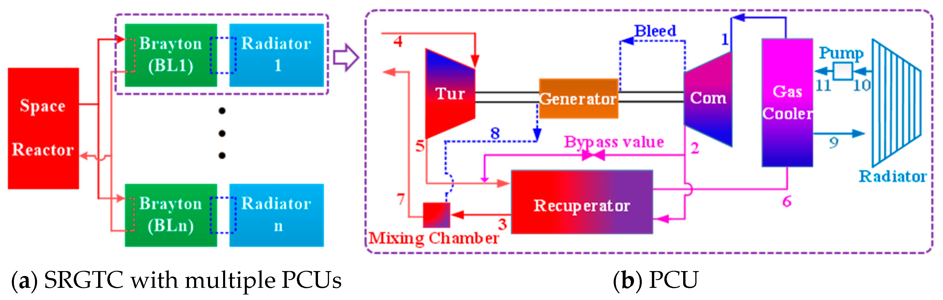
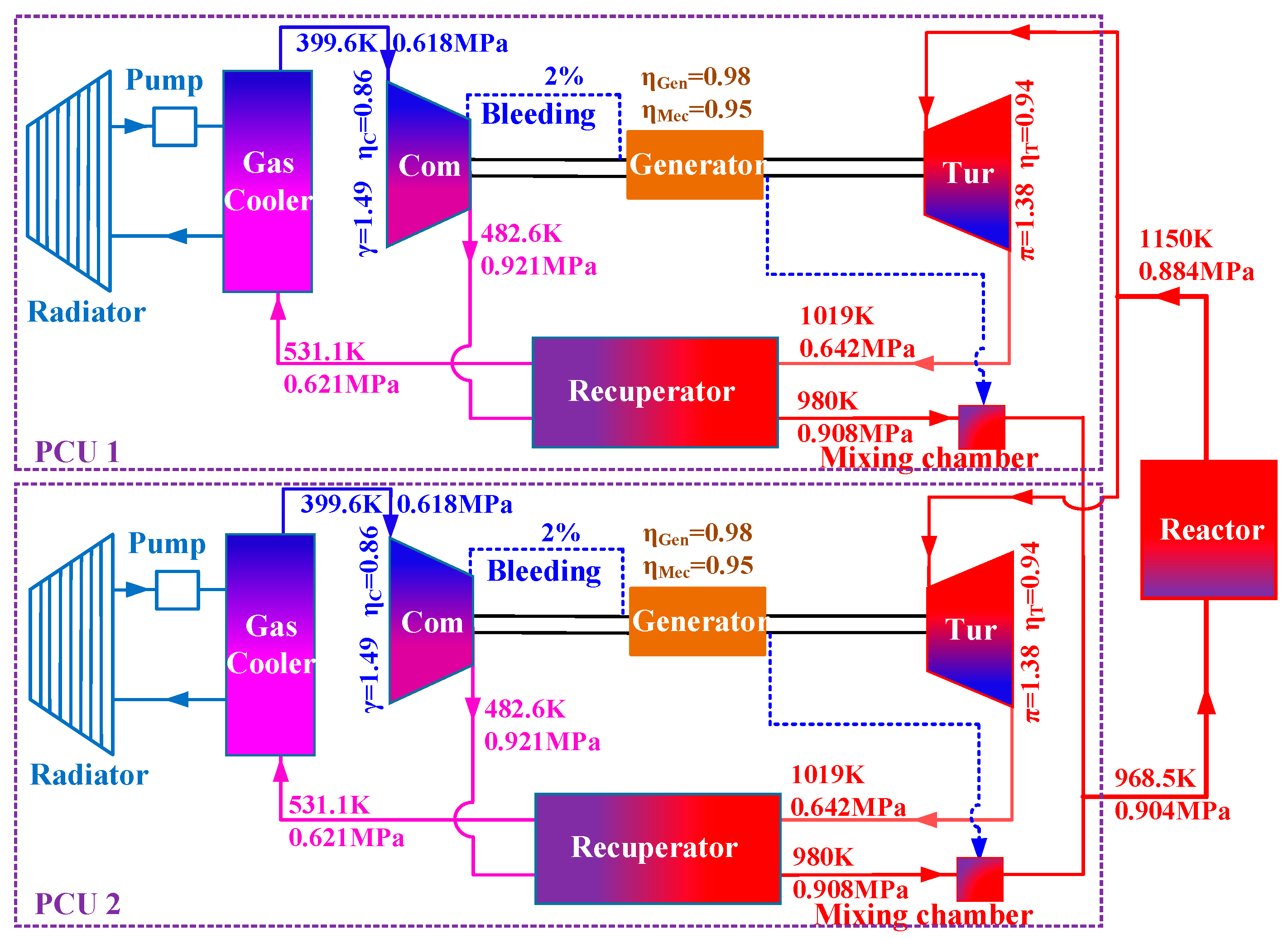
2.1. System Description
2.2. Dynamic Model of the SRGTC
- (1)
- The SRGTC is a closed adiabatic system, therefore, there is no working fluid leakage and component heat dissipation.
- (2)
- The proportion of accelerated pressure drop to the total pressure drop is small, therefore, the accelerated pressure drop in the momentum conservation equation is ignored.
- (3)
- To simplify the model and program and save computational costs, the one-dimensional lumped parameter model is adopted.
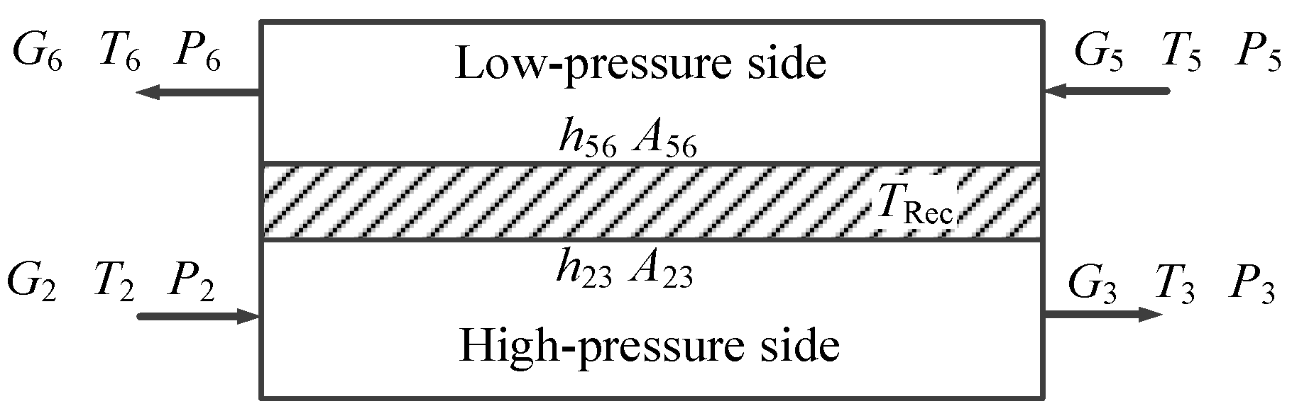
2.2.1. Recuperator
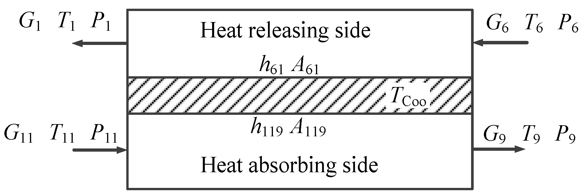
2.2.2. Gas Cooler
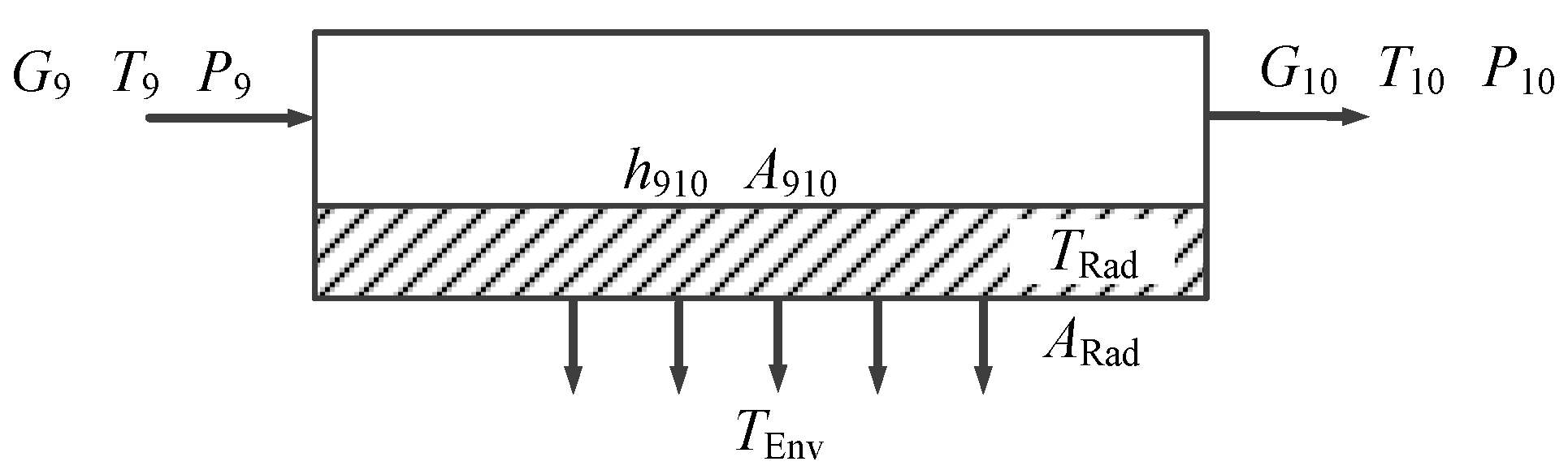
2.2.3. Radiator
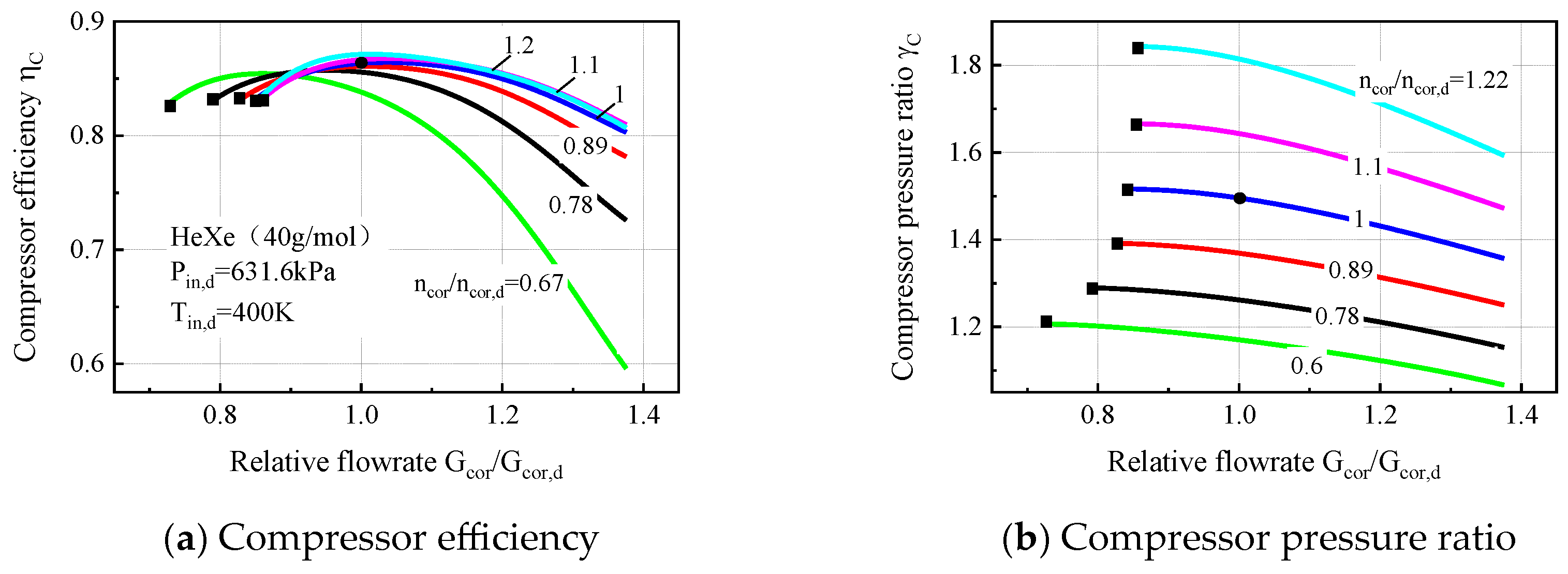
2.2.4. Turbomachine
2.2.5. Bypass Value
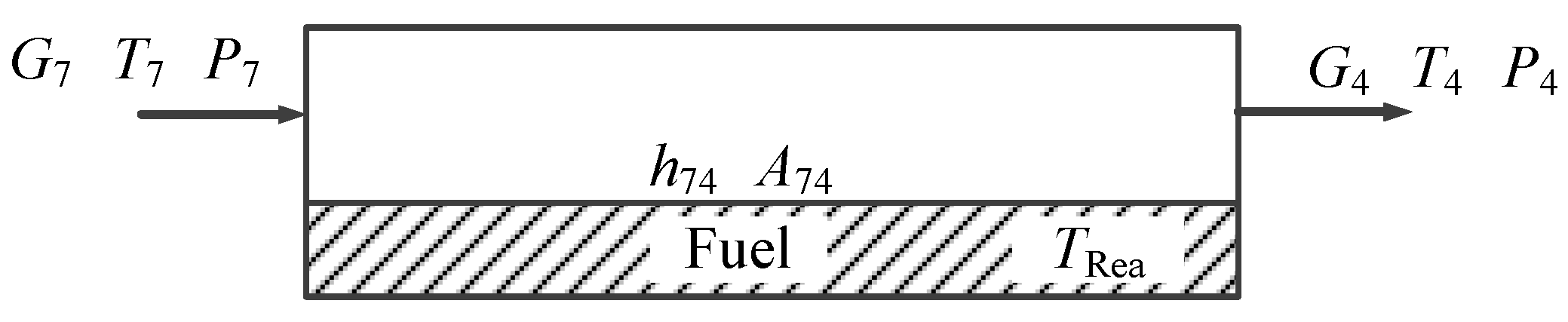
2.2.6. Reactor
2.2.7. Overall Parameters
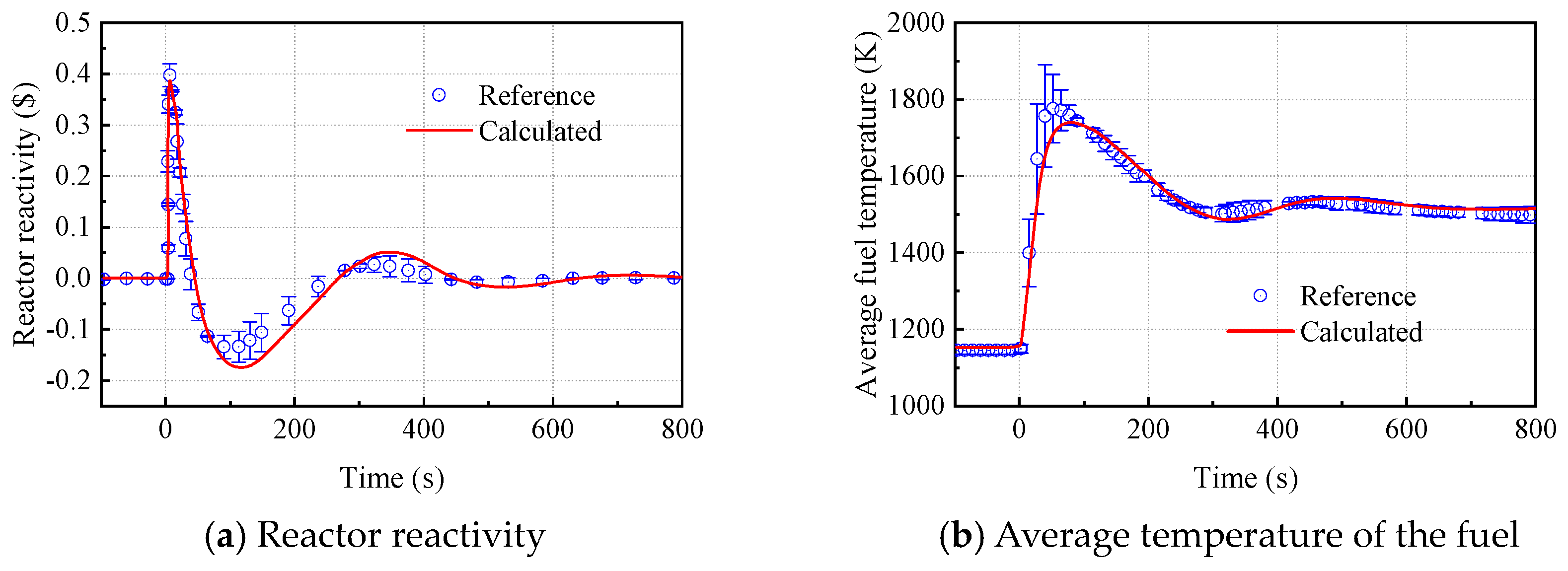
2.3. Model Validation
3. Results and Discussion
3.1. Influence of Radiator Loss on the SRGTC
3.2. Safety Boundary of the SRGTC for Radiator Loss Accidents
3.3. Coupling Influence of One-PCU Radiator Loss on Other PCUs
4. Conclusions
- (1)
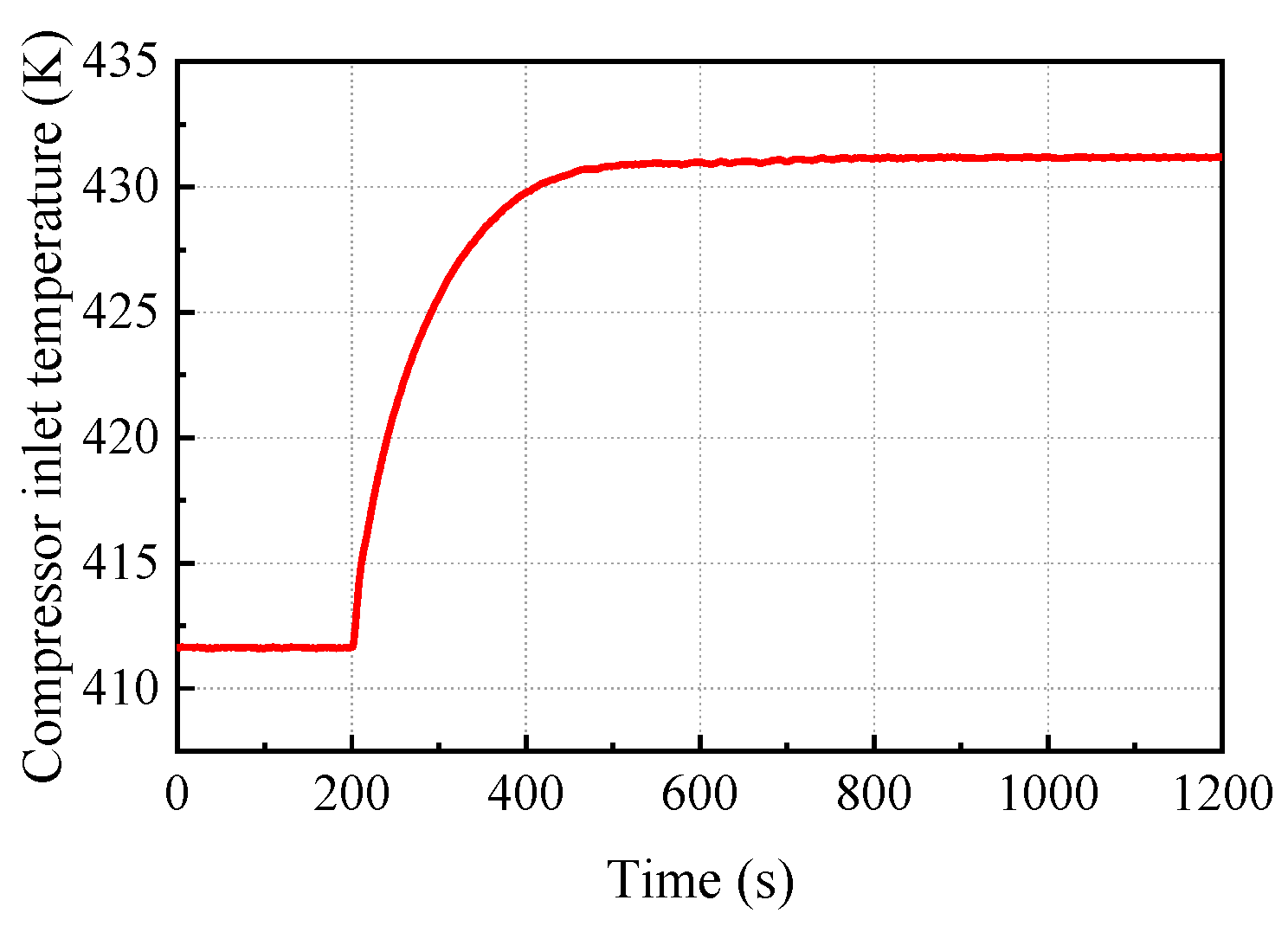
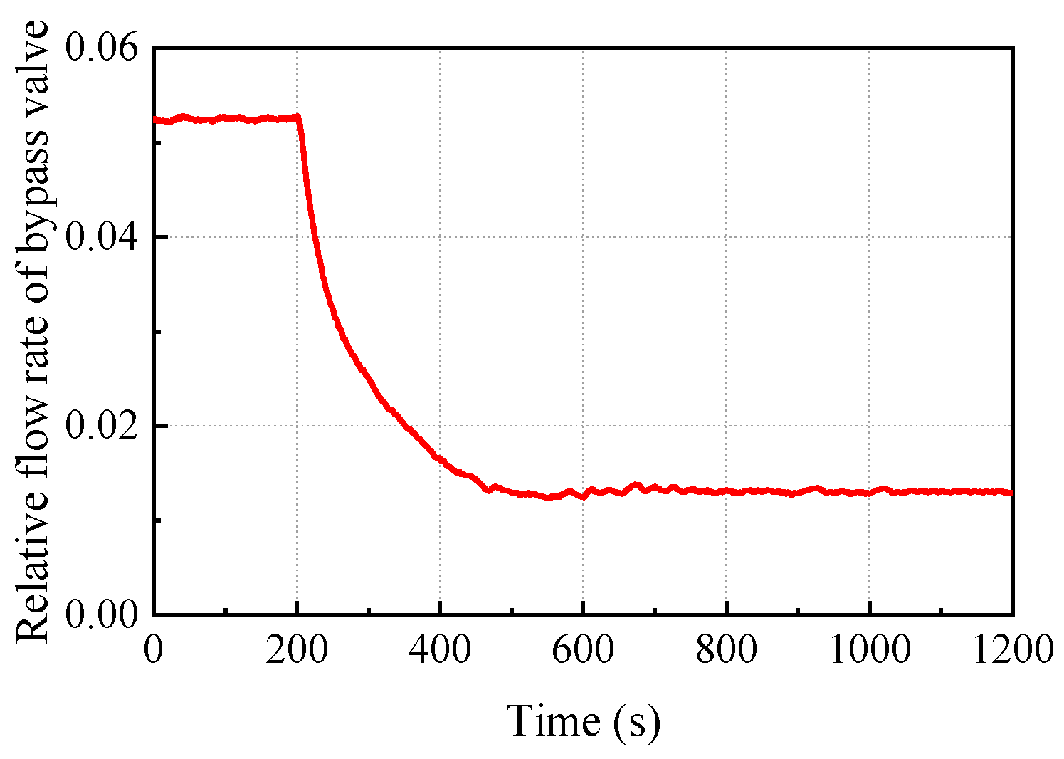
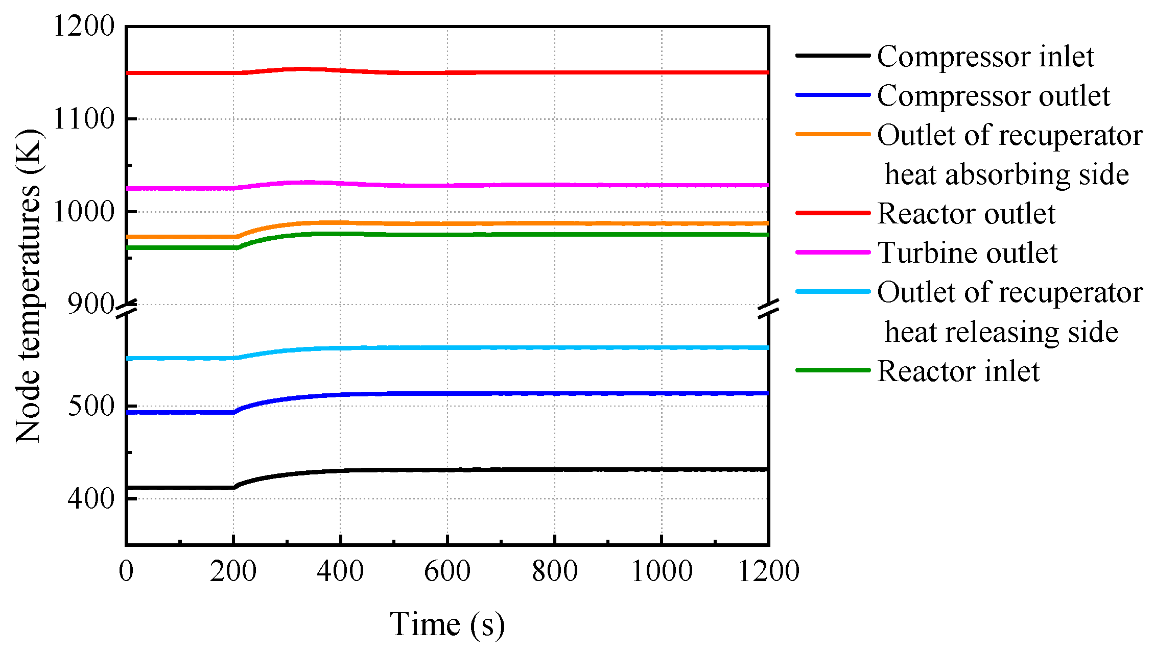
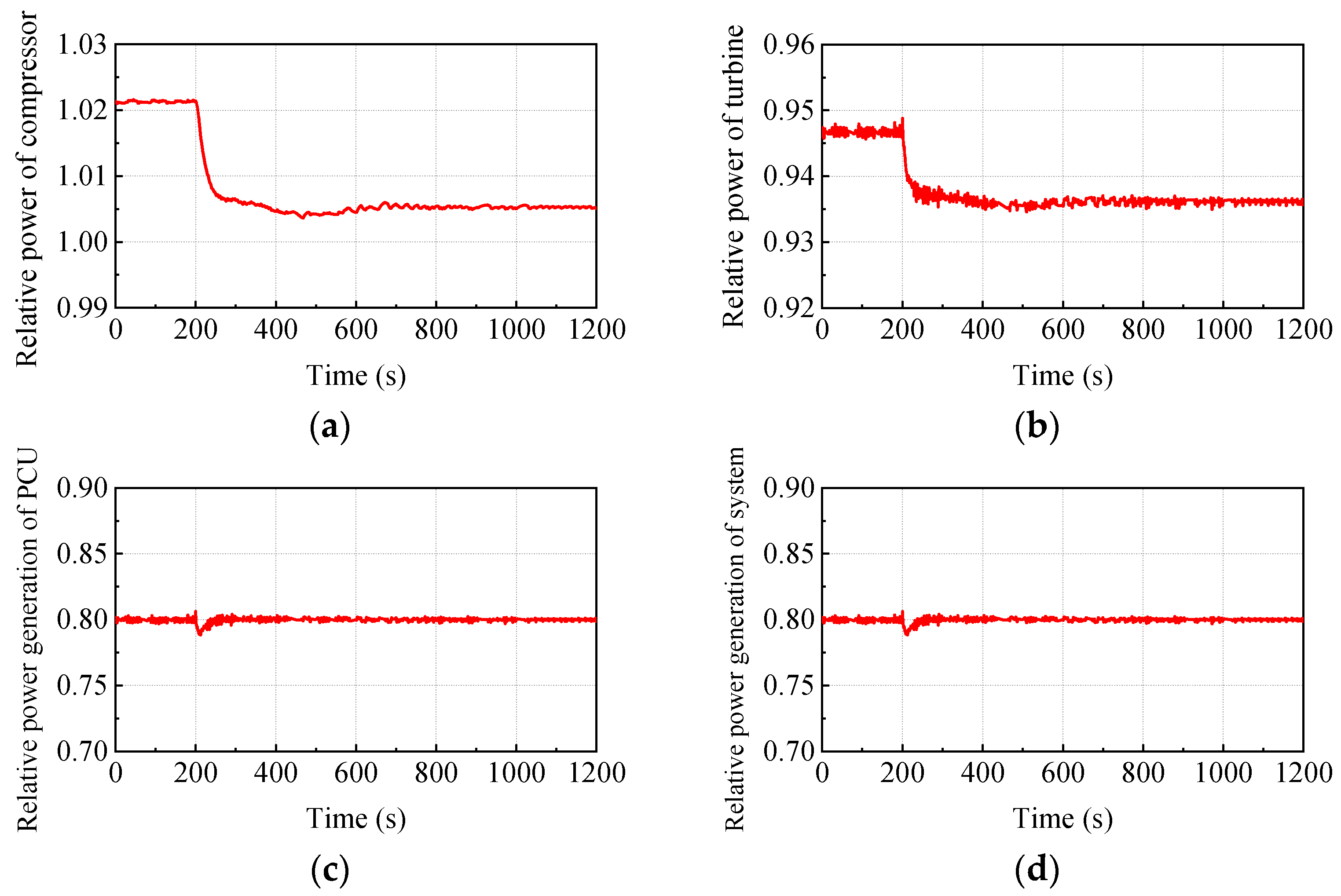
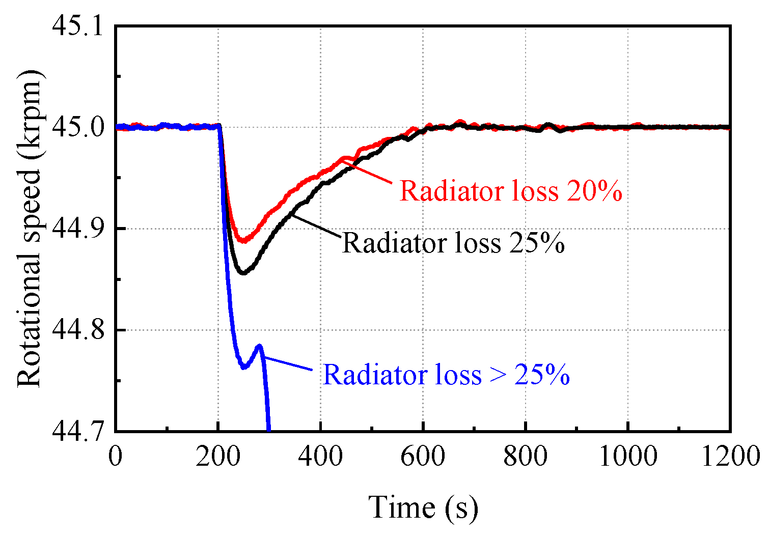
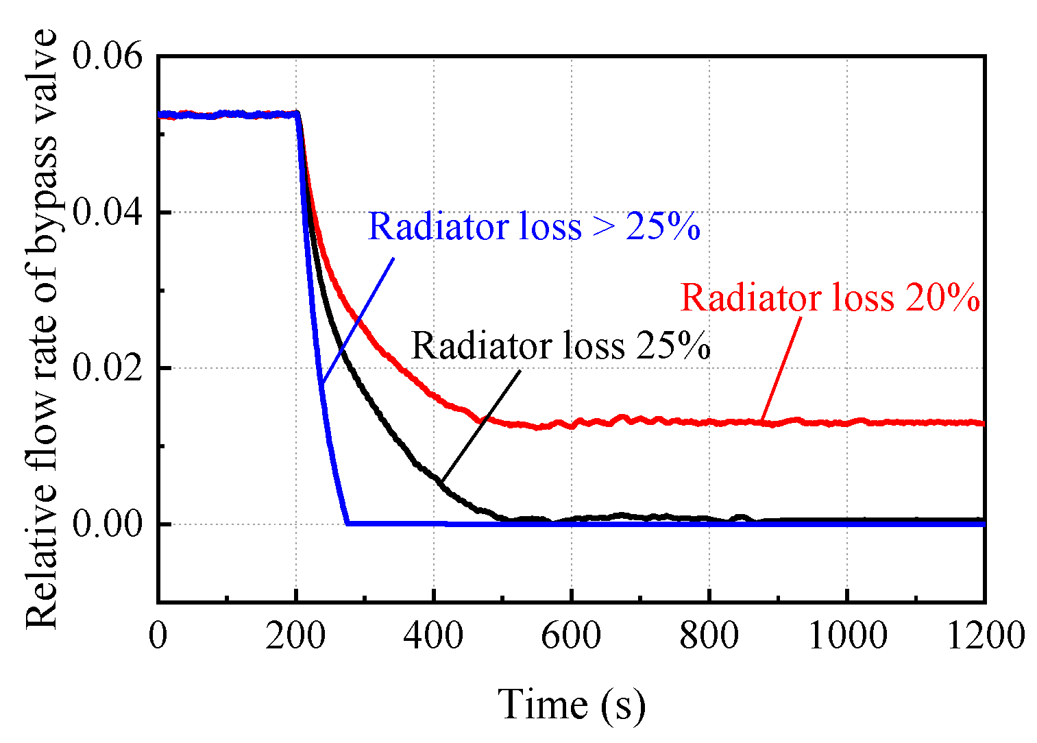
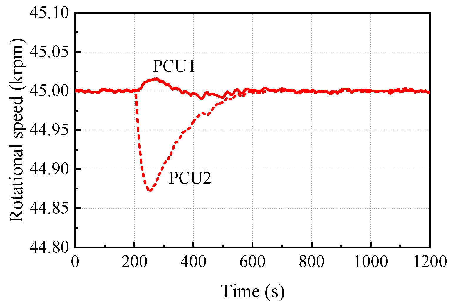
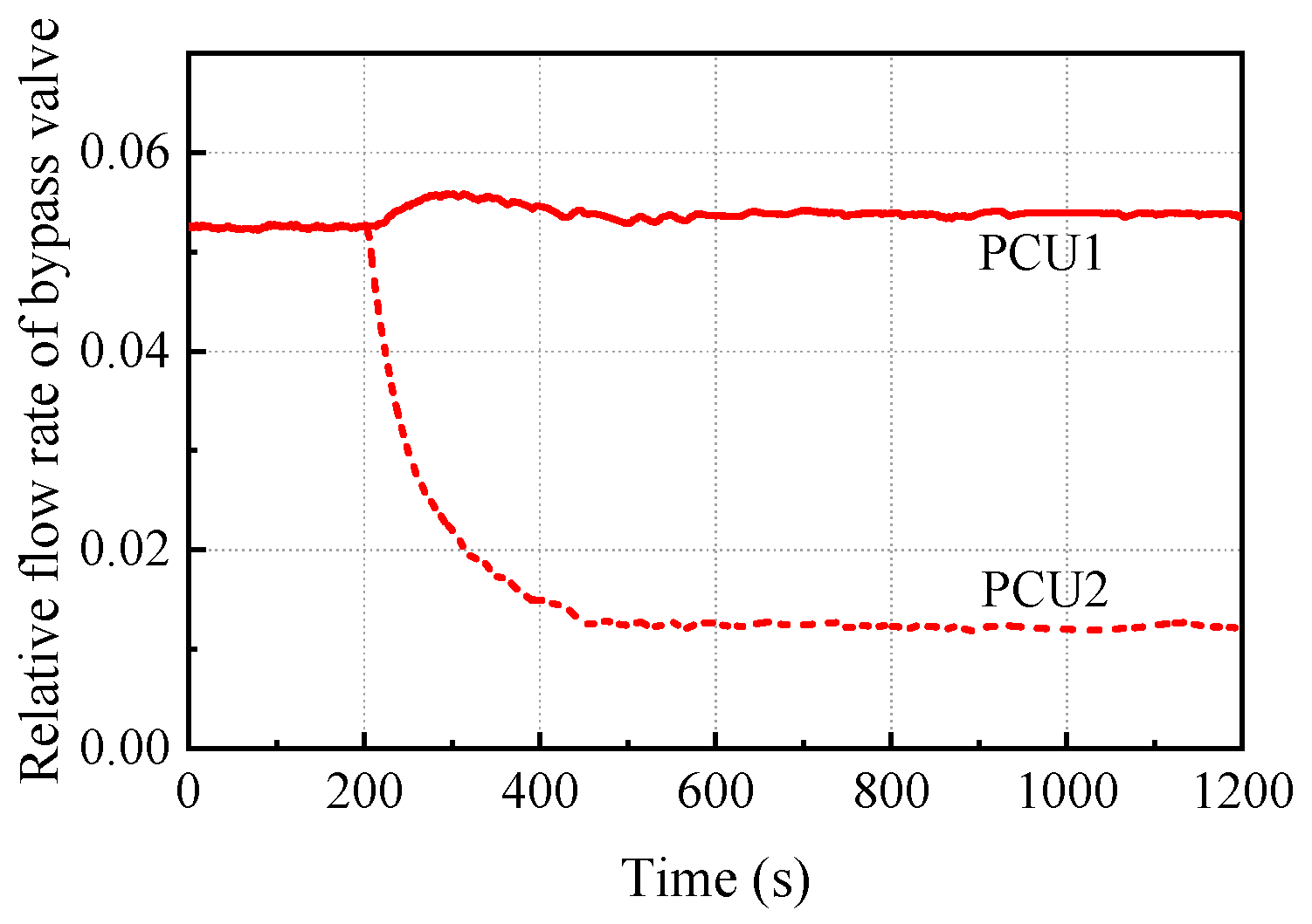
- The bypass valve control can ensure the safe and stable operation of the SRGTC. The waste heat of the system is accumulated in the radiator for the radiator loss, which increases the consumed power of the compressor and further leads to speed fluctuations. The bypass valve control and the temperature negative feedback effect can ensure the safe operation of the shaft and the reactor under partial radiator loss.
- (2)
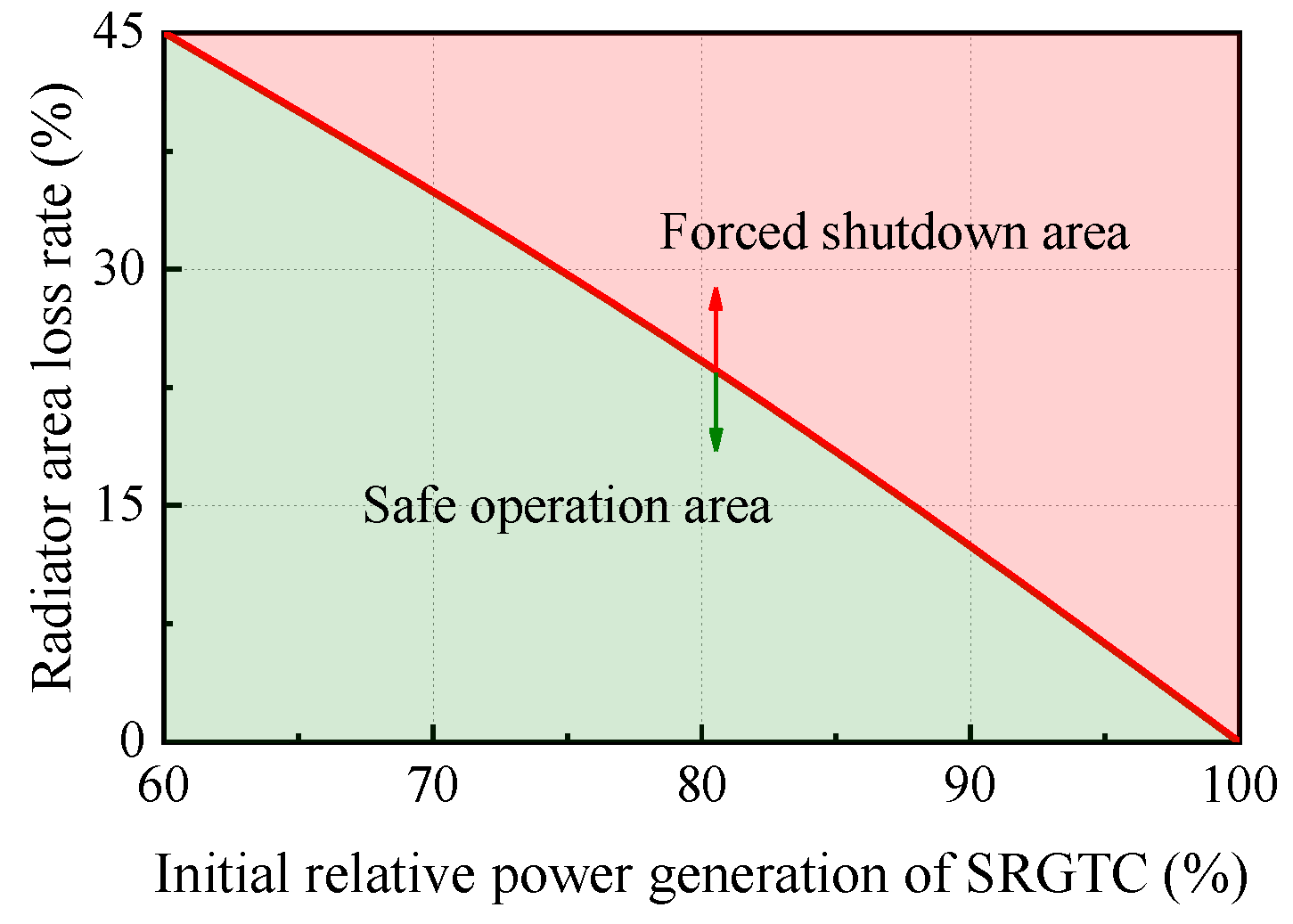
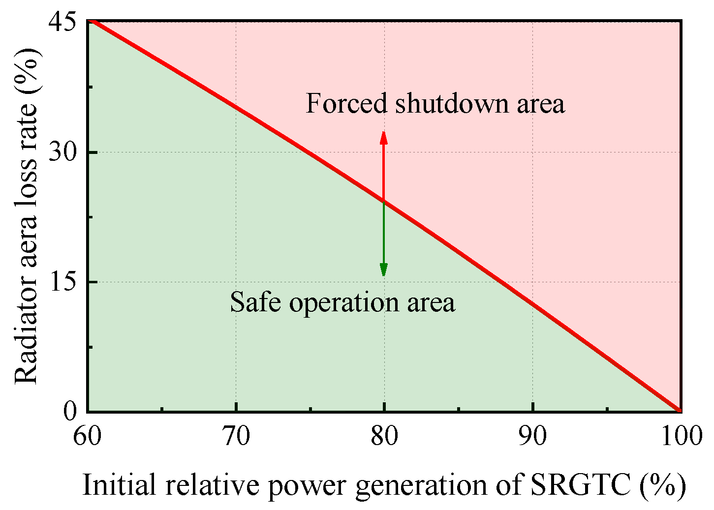
- It is found that the SRGTC has a safety boundary for radiator loss accidents. More heat sink loss increases the power consumption of the compressor. The speed decreases far below the rated speed and exceeds the safety margin of the bypass valve control. The continuous decrease in speed leads to system shutdown, and there is a safety boundary of the radiator area loss.
- (3)
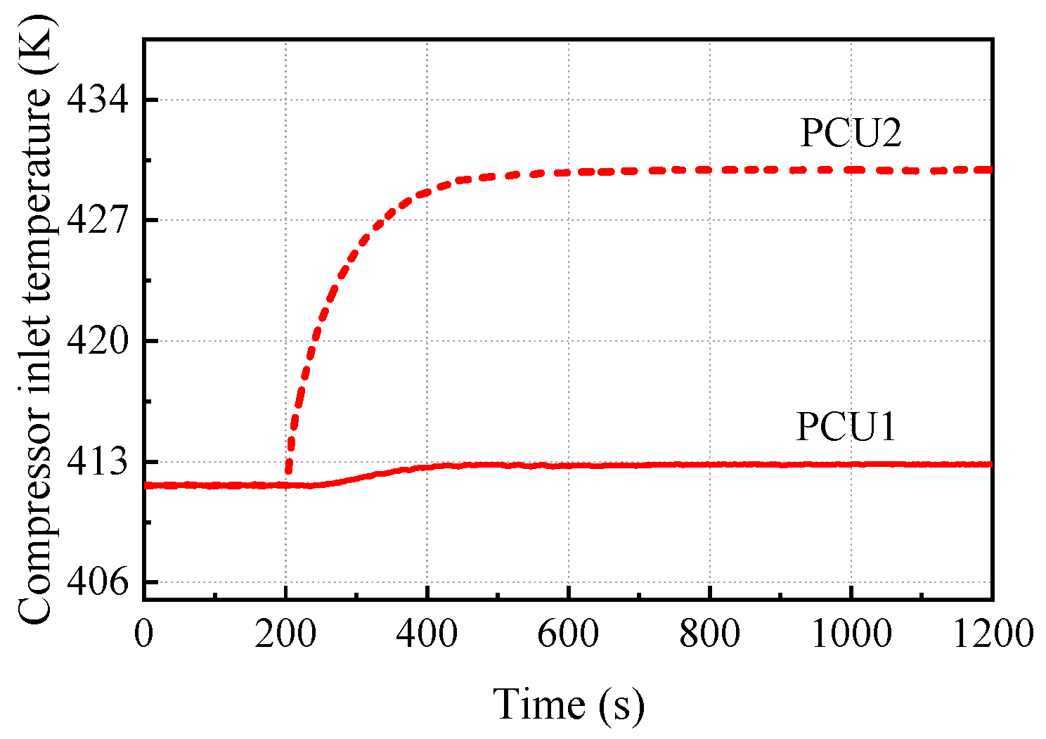
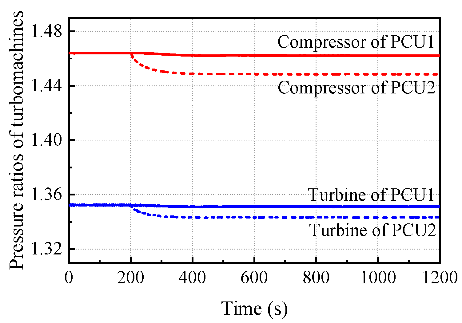
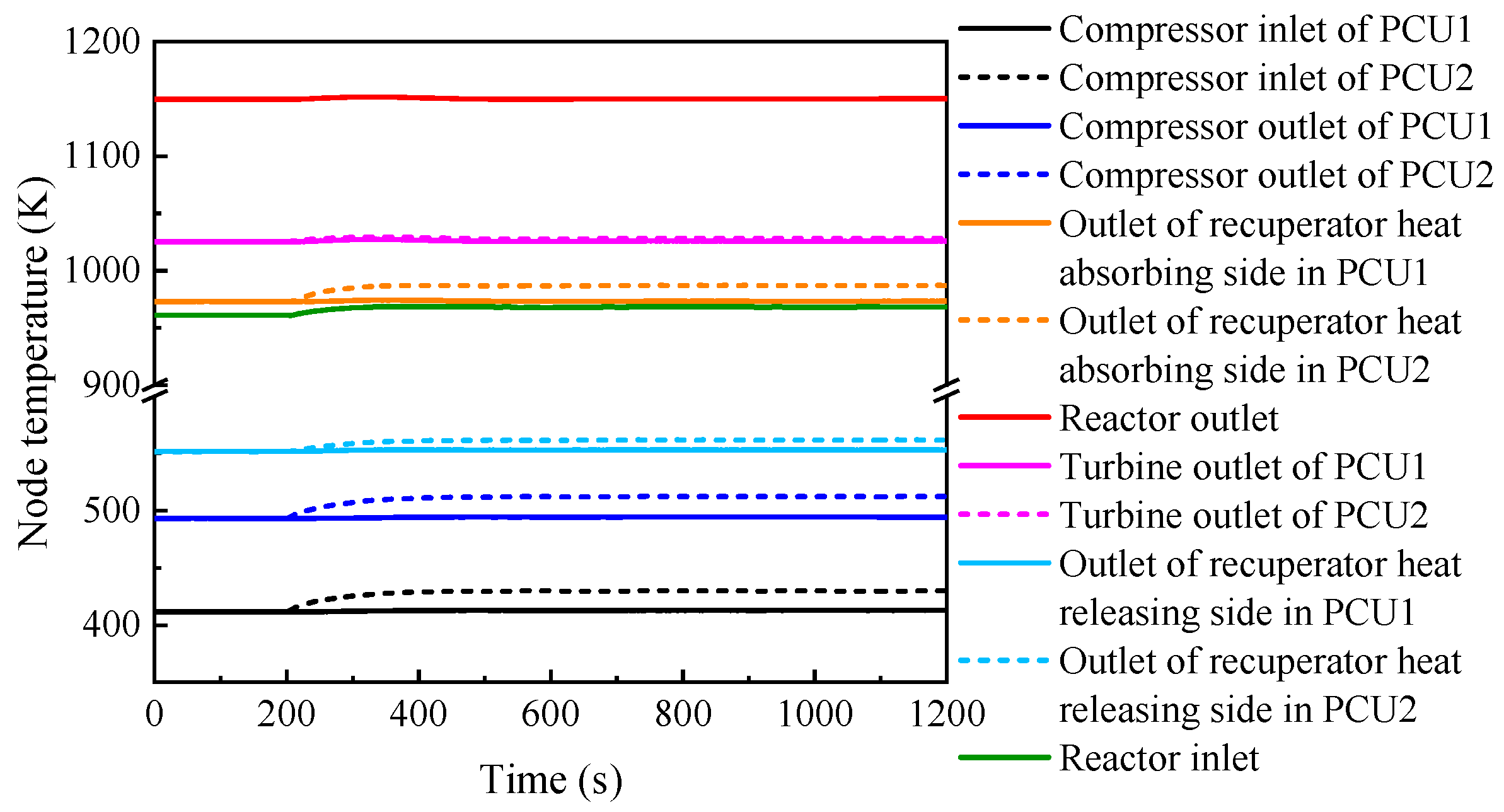
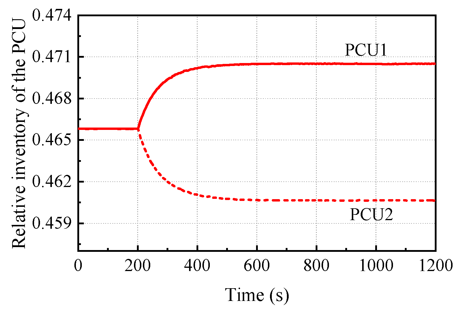
- There is a coupling effect between PCUs of the SRGTC after one-PCU radiator loss. It redistributes the working fluid inventory between the PCU modules. The accumulation of the waste heat in the accident PCU module increases the average temperature and decreases working fluid inventory of the accident PCU, which further increases safety boundary of the accident PCU.
Author Contributions
Funding
Data Availability Statement
Conflicts of Interest
Nomenclature
| area for heat transfer, [] | |
| specific heat of constant pressure, [] | |
| specific heat of component, [] | |
| density of the precursors | |
| diameter, [] | |
| friction loss coefficient | |
| local loss coefficient | |
| mass flow rate, [] | |
| heat transfer coefficient | |
| moment of inertia, [kg] | |
| proportional gain | |
| length of the flow channel, [] | |
| mass of the working fluid or component, [] | |
| inventory of helium and xenon, [] | |
| number of single PCU components | |
| number of power conversion units | |
| load of generator | |
| rotational speed of the shaft, [] | |
| relative neutron density | |
| pressure, [] | |
| power generation of the PCU, [] | |
| power generation of the system, [] | |
| thermal power of the reactor, [] | |
| power of the turbomachine, [] | |
| gas constant, [] | |
| temperature, [K] | |
| time, [s] | |
| velocity of the working fluid, [] | |
| volume of the component, [] | |
| gas compressibility factor |
Greek Letters
| feedback coefficient | |
| density, [] | |
| fraction of the delayed neutron | |
| pressure loss rate of the component | |
| pressure ratio of the turbomachine | |
| efficiency of components or system | |
| emissivity | |
| Stefan–Boltzmann constant | |
| integral and differential constant | |
| opening of the bypass valve |
Subscripts
| Byp | bypass |
| Com | compressor |
| Coo | cooler |
| Env | environment |
| Fue | fuel |
| Gen | generator |
| Loa | load |
| Rad | radiator |
| Rea | reactor |
| Rec | recuperator |
| Sys | system |
| Tur | turbine |
Abbreviations
| PCU | power conversion unit |
| SRGTC | space reactor gas turbine cycle |
| SRGTC-DPCU | SRGTC with dual PCUs |
References
- Ayodele, O.L.; Luta, D.N.; Kahn, M.T. A Micro-Nuclear Power Generator for Space Missions. Energies 2023, 16, 4422. [Google Scholar] [CrossRef]
- Ge, L.; Li, H.; Tian, X.; Ouyang, Z.; Kang, X.; Li, D.; Shan, J.; Jiang, X. Improvement and validation of the system analysis model and code for heat-pipe-cooled microreactor. Energies 2022, 15, 2586. [Google Scholar] [CrossRef]
- Cheng, K.; Li, J.; Yu, J.; Qin, J.; Jing, W. Dynamic Characteristics Analysis for a Novel Double-Rotor He-Xe Closed-Brayton-Cycle Space Nuclear Power Generation System. Energies 2023, 16, 6620. [Google Scholar] [CrossRef]
- Zhou, B.; Sun, J.; Sun, Y. Investigation on Laminar Flow and Heat Transfer of Helium–Xenon Gas Mixtures with Variable Properties. Energies 2023, 16, 1899. [Google Scholar] [CrossRef]
- Levine, B. Space Nuclear Power Plant Pre-Conceptual Design Report, for Information; Knolls Atomic Power Laboratory: Niskayuna, NY, USA, 2006. [Google Scholar]
- Zhang, R.; Guo, K.; Wang, C.; Zhang, D.; Tian, W.; Qiu, S.; Su, G.H.; Deng, J. Thermal-hydraulic analysis of gas-cooled space nuclear reactor power system with closed Brayton cycle. Int. J. Energy Res. 2020, 45, 11851–11867. [Google Scholar] [CrossRef]
- Qin, H.; Zhang, R.; Guo, K.; Wang, C.; Tian, W.; Su, G.; Qiu, S. Thermal-hydraulic analysis of an open-grid megawatt gas-cooled space nuclear reactor core. Int. J. Energy Res. 2021, 45, 11616–11628. [Google Scholar] [CrossRef]
- Li, Z.; Yang, X.; Wang, J.; Zhang, Z. Off-design performance and control characteristics of space reactor closed Brayton cycle system. Ann. Nucl. Energy 2019, 128, 318–329. [Google Scholar] [CrossRef]
- Wang, C.; Zhang, R.; Guo, K.; Zhang, D.; Tian, W.; Qiu, S.; Su, G. Dynamic simulation of a space gas-cooled reactor power system with a closed Brayton cycle. Front. Energy 2021, 15, 916–929. [Google Scholar] [CrossRef]
- Meng, T.; Cheng, K.; Zhao, F.; Xia, C.; Tan, S. Dynamic simulation of the gas-cooled space nuclear reactor system using SIMCODE. Ann. Nucl. Energy 2021, 159, 108293. [Google Scholar] [CrossRef]
- Ma, W.; Ye, P.; Gao, Y.; Yang, X. Study on the load loss characteristics of a space nuclear power system with multi Brayton loops. Ann. Nucl. Energy 2023, 185, 109702. [Google Scholar] [CrossRef]
- Wright, S. Preliminary Results of a Dynamic Systems Model for a Closed-Loop Brayton Cycle System Coupled to a Nuclear Reactor. In Proceedings of the International Energy Conversion Engineering Conference, Portsmouth, VA, USA, 17–21 August 2003. [Google Scholar]
- Wright, S.A.; Sanchez, T. Dynamic modeling and control of nuclear reactors coupled to closed-loop Brayton cycle systems using SIMULINK™. AIP Conf. Proc. Am. Inst. Phys. 2005, 746, 991–1004. [Google Scholar]
- Wright, S.A.; Lipinski, R.J.; Vernon, M.E.; Sanchez, T. Closed Brayton Cycle Power Conversion Systems for Nuclear Reactors; Sandia National Laboratory: Albuquerque, NM, USA, 2006. [Google Scholar]
- Jin, Z.; Wang, C.; Liu, X.; Dai, Z.; Tian, W.; Su, G.; Qiu, S. Operation and safety analysis of space lithium-cooled fast nuclear reactor. Ann. Nucl. Energy 2022, 166, 108729. [Google Scholar] [CrossRef]
- Jin, Z.; Wang, C.; Liu, X.; Dai, Z.; Tian, W.; Qiu, H.; Su, G. Thermal-hydraulic and Safety Analysis of Space Hundred-kilowatt Lithium-cooled Fast Reactor. At. Energy Sci. Technol. 2022, 56, 443. [Google Scholar]
- Ma, W.; Ye, P.; Gao, Y.; Yang, X. Comparative study on sequential and simultaneous startup performance of space nuclear power system with multi brayton loops. Acta Astronaut. 2022, 199, 142–152. [Google Scholar] [CrossRef]
- Johnson, P.; Mason, L. Performance and Operational Characteristics for a Dual Brayton Space Power System with Common Gas Inventory. In Proceedings of the 4th International Energy Conversion Engineering Conference and Exhibit (IECEC), San Diego, CA, USA, 26–29 June 2006. [Google Scholar] [CrossRef]
- Ashcroft, J.; Belanger, S.; Burdge, W.; Clementoni, E.; Jensen, K.; Proctor, N.B.; Zemo-Fulkerson, A. Key Factors Influencing the Decision on the Number of Brayton Units for the Prometheus Space Reactor. AIP Conf. Proc. 2007, 880, 522–540. [Google Scholar]
- Ma, W.; Ye, P.; Zhao, G.; Yang, X.; Wang, J. Effect of cooling schemes on performance of MW-class space nuclear closed Brayton cycle. Ann. Nucl. Energy 2021, 162, 108485. [Google Scholar] [CrossRef]
- Taylor, M.; Bauer, K.; McEligot, D. Internal forced convection to low-Prandtl-number gas mixtures. Int. J. Heat Mass Transf. 1988, 31, 13–25. [Google Scholar] [CrossRef]
- von Arx, A.V.; Ceyhan, I. Laminar heat transfer for low Prandtl number gases. AIP Conf. Proc. Am. Inst. Phys. 1991, 217, 719–722. [Google Scholar]
- Hong, J.; Lee, J.; Eoh, J. Study on convective heat transfer correlations for sodium-to-sodium heat exchanger based on STELLA-1 experimental results. Nucl. Eng. Des. 2020, 371, 110963. [Google Scholar] [CrossRef]
- Yuan, Z.; Zheng, Q.; Yue, G.; Jiang, Y. Performance evaluation on radial turbines with potential working fluids for space closed Brayton cycle. Energy Convers. Manag. 2021, 243, 114368. [Google Scholar] [CrossRef]
- Gallo, B.M.; El-Genk, M.S. Brayton rotating units for space reactor power systems. Energy Convers. Manag. 2009, 50, 2210–2232. [Google Scholar] [CrossRef]
- El-Genk, M.S.; Gallo, B.M. High-Power Brayton Rotating Unit for Reactor and Solar Dynamic Power Systems. J. Propuls. Power 2010, 26, 167–176. [Google Scholar] [CrossRef]
- Gallo, B.M.; El-Genk, M.S.; Tournier, J.M. Compressor and turbine models of Brayton units for space nuclear power systems. AIP Conf. Proc. 2007, 880, 472–482. [Google Scholar]
- El-Genk, M.; Gallo, B. High Performance Brayton Rotating Unit (UNM-BRU-3) for Space Reactor Power Systems. In Proceedings of the International Energy Conversion Engineering Conference, Denver, CO, USA, 2–5 August 2009. [Google Scholar]
- Ming, Y.; Liu, K.; Zhao, F.; Fang, H.; Tan, S.; Tian, R. Dynamic modeling and validation of the 5 MW small modular supercritical CO2 Brayton-Cycle reactor system. Energy Convers. Manag. 2022, 253, 115184. [Google Scholar] [CrossRef]
- Kim, J.H.; NO, H.C.; Kim, H.M.; Lim, H.S. A system analysis tool with a 2D gas turbine modeling for the load transients of HTGRS. Nucl. Eng. Des. 2009, 239, 2459–2467. [Google Scholar] [CrossRef]
- Nakoryakov, V.E.; Vitovsky, O.V. Study of heat transfer of a helium–xenon mixture in heated channels with different cross-sectional shapes. J. Appl. Mech. Tech. Phys. 2017, 58, 664–669. [Google Scholar] [CrossRef]
- Nakoryakov, V.E.; Elistratov, S.L.; Vitovsky, O.V.; Slesareva, E.Y. Experimental investigation of heat transfer in helium-xenon mixtures in triangle channels. J. Eng. Thermophys. 2015, 24, 139–142. [Google Scholar] [CrossRef]
- El-Genk, M.S.; Tournier, J.-M. Noble gas binary mixtures for gas-cooled reactor power plants. Nucl. Eng. Des. 2008, 238, 1353–1372. [Google Scholar] [CrossRef]
- Xu, C.; Kong, F.; Yu, D.; Yu, J.; Khan, M.S. Influence of non-ideal gas characteristics on working fluid properties and thermal cycle of space nuclear power generation system. Energy 2021, 222, 119881. [Google Scholar] [CrossRef]


| Node Parameters | Pressure (kPa) | Temperature (K) | ||||
|---|---|---|---|---|---|---|
| Simulated Values | Design Values | Error | Simulated Values | Design Values | Error | |
| Turbine inlet | 883.7 | 883.6 | 0.01% | 1150.7 | 1150 | 0.06% |
| Turbine outlet | 642.4 | 643.0 | −0.09% | 1019.4 | 1018.8 | 0.06% |
| Inlet of recuperator low-pressure side | 620.7 | 620.9 | −0.03% | 531.1 | 521.8 | 1.75% |
| Compressor inlet | 617.9 | 618.1 | −0.03% | 399.6 | 400 | −0.10% |
| Compressor outlet | 921.2 | 921.0 | 0.02% | 482.6 | 482.5 | 0.02% |
| Outlet of recuperator high-pressure side | 907.7 | 907.5 | 0.02% | 980.0 | 981.3 | −0.13% |
| Reactor inlet | 903.5 | 898.3 | 0.58% | 968.5 | 970.3 | −0.19% |
| System Parameters | Simulated Values | Design Values | Error |
|---|---|---|---|
| 47.26 | 47.91 | −1.38% | |
| 23.63 | 23.95 | −1.35% | |
| Reactor power (kWth) | 4561.4 | 4561 | 0.01% |
| PCU power generation (kW) | 503.2 | 499.8 | 0.68% |
| SRGTC power generation (kW) | 1006.4 | 999.6 | 0.68% |
| Power generation efficiency (%) | 22.06 | 21.91 | 0.68% |
Disclaimer/Publisher’s Note: The statements, opinions and data contained in all publications are solely those of the individual author(s) and contributor(s) and not of MDPI and/or the editor(s). MDPI and/or the editor(s) disclaim responsibility for any injury to people or property resulting from any ideas, methods, instructions or products referred to in the content. |
© 2024 by the authors. Licensee MDPI, Basel, Switzerland. This article is an open access article distributed under the terms and conditions of the Creative Commons Attribution (CC BY) license (https://creativecommons.org/licenses/by/4.0/).
Share and Cite
Ma, W.; Ye, P.; Gao, Y.; Hao, Y.; Yao, Y.; Yang, X. Analysis of the Radiator Loss Safety Boundary of a Space Reactor Gas Turbine Cycle with Multiple PCU Modules. Energies 2024, 17, 597. https://doi.org/10.3390/en17030597
Ma W, Ye P, Gao Y, Hao Y, Yao Y, Yang X. Analysis of the Radiator Loss Safety Boundary of a Space Reactor Gas Turbine Cycle with Multiple PCU Modules. Energies. 2024; 17(3):597. https://doi.org/10.3390/en17030597
Chicago/Turabian StyleMa, Wenkui, Ping Ye, Yue Gao, Yadong Hao, Yi Yao, and Xiaoyong Yang. 2024. "Analysis of the Radiator Loss Safety Boundary of a Space Reactor Gas Turbine Cycle with Multiple PCU Modules" Energies 17, no. 3: 597. https://doi.org/10.3390/en17030597