
Electromagnetic Characterization of Silicon–Iron Additively Manufactured Cores for Electric Machines


Abstract
1. Introduction
- Fragility of Material: Increased silicon content can make ferromagnetic sheets more brittle. This can lead to difficulties when processing and handling the sheets.
- High Production Costs: The introduction of high silicon content can result in higher production costs due to the need for more sophisticated machinery and processes to ensure the desired quality of the material.
- Weldability Issues: High silicon content can affect the weldability of sheets. Welding of materials with high silicon content may require additional attention and special techniques to avoid the formation of defects in welded joints.
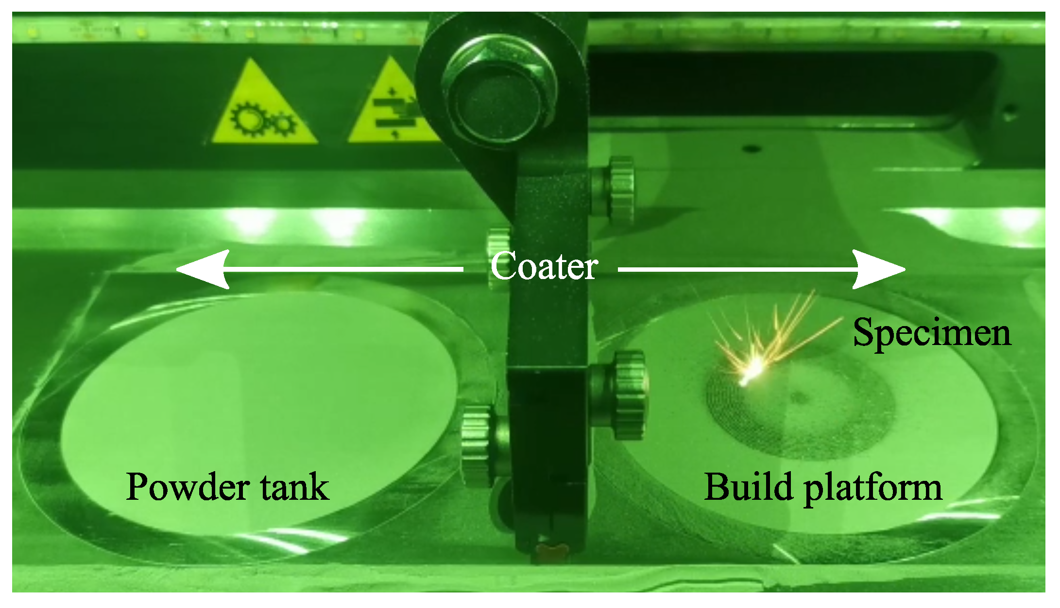
2. Description of the Manufacturing Process
- 1.
- The realization of a CAD model of the specimen to be produced;
- 2.
- The manufacturing process itself;
- 3.
- The post-process operations to finalize the sample.
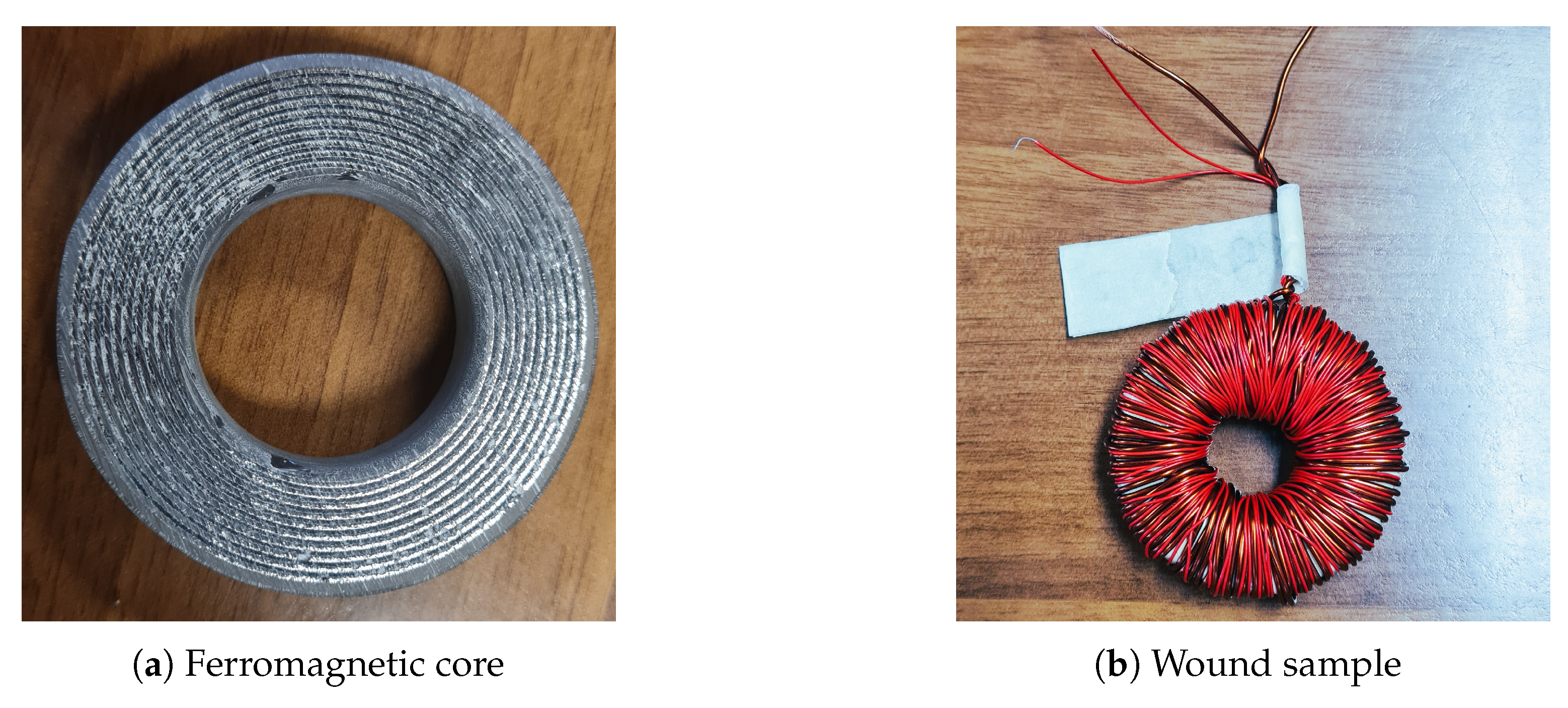
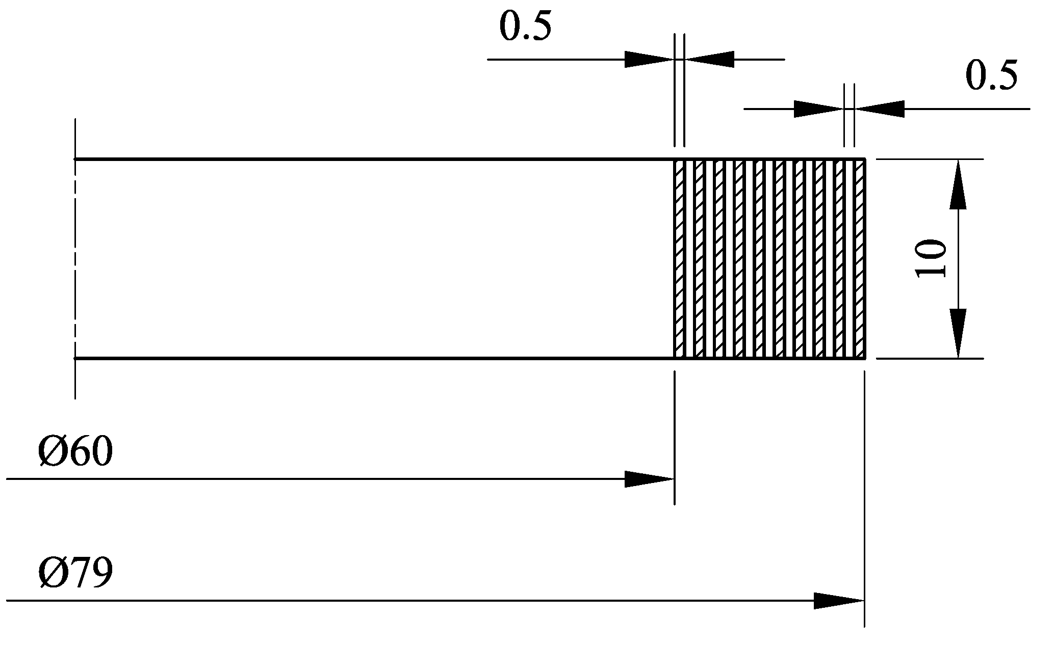
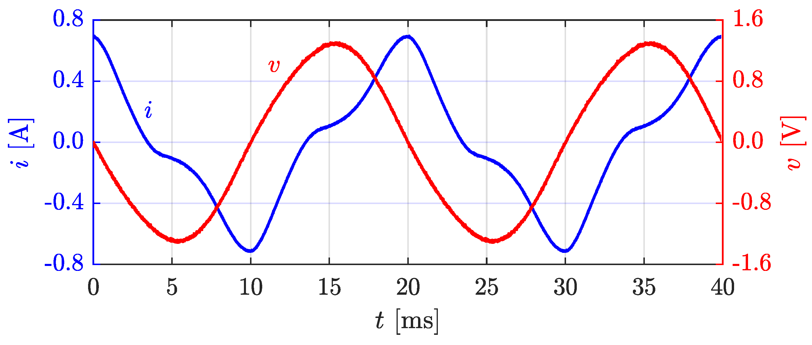
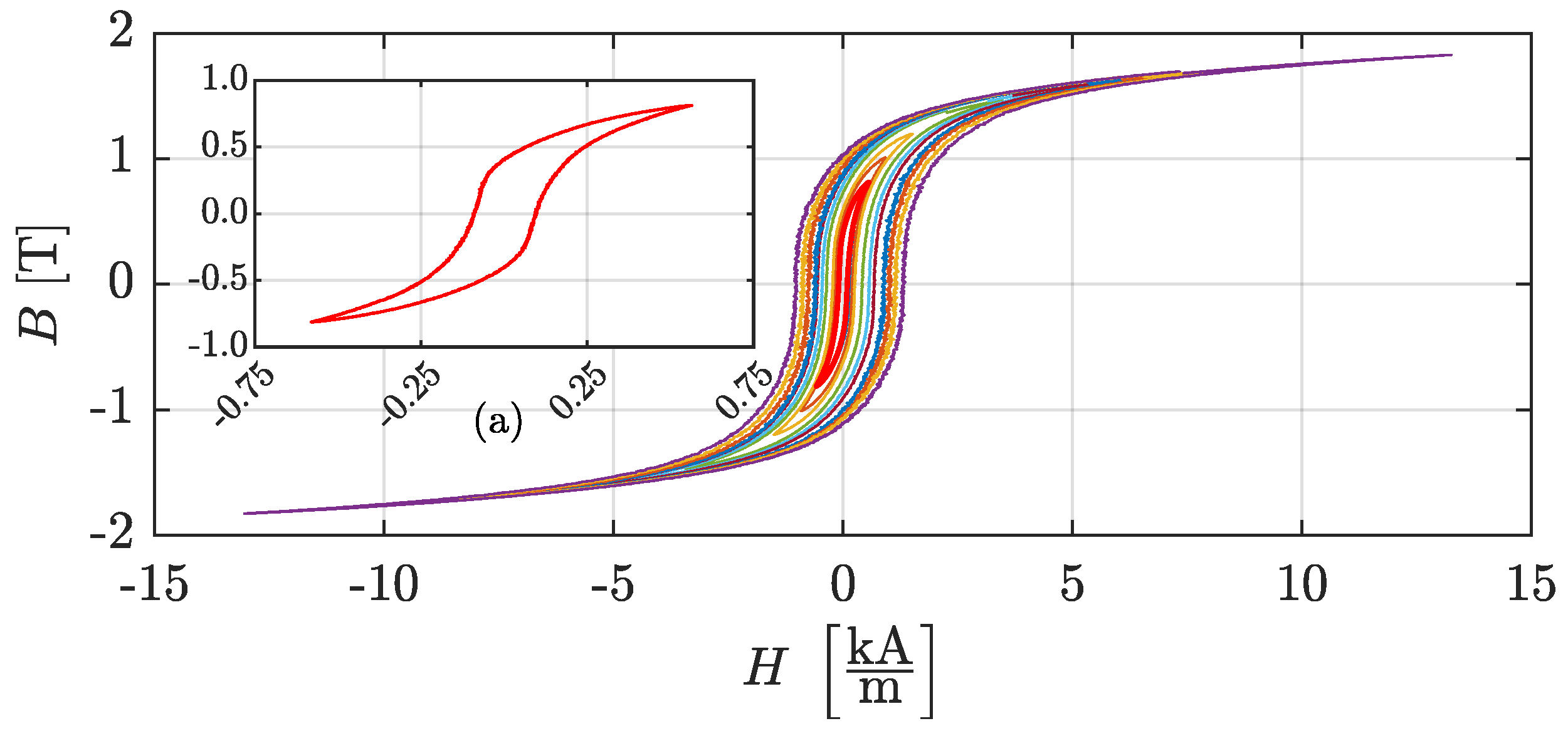
3. Characterization of the Toroid
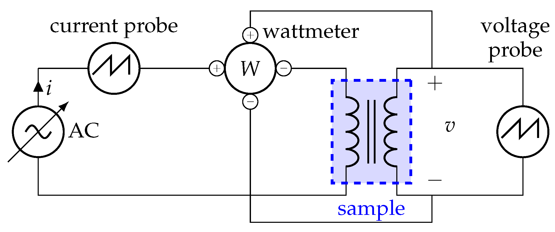
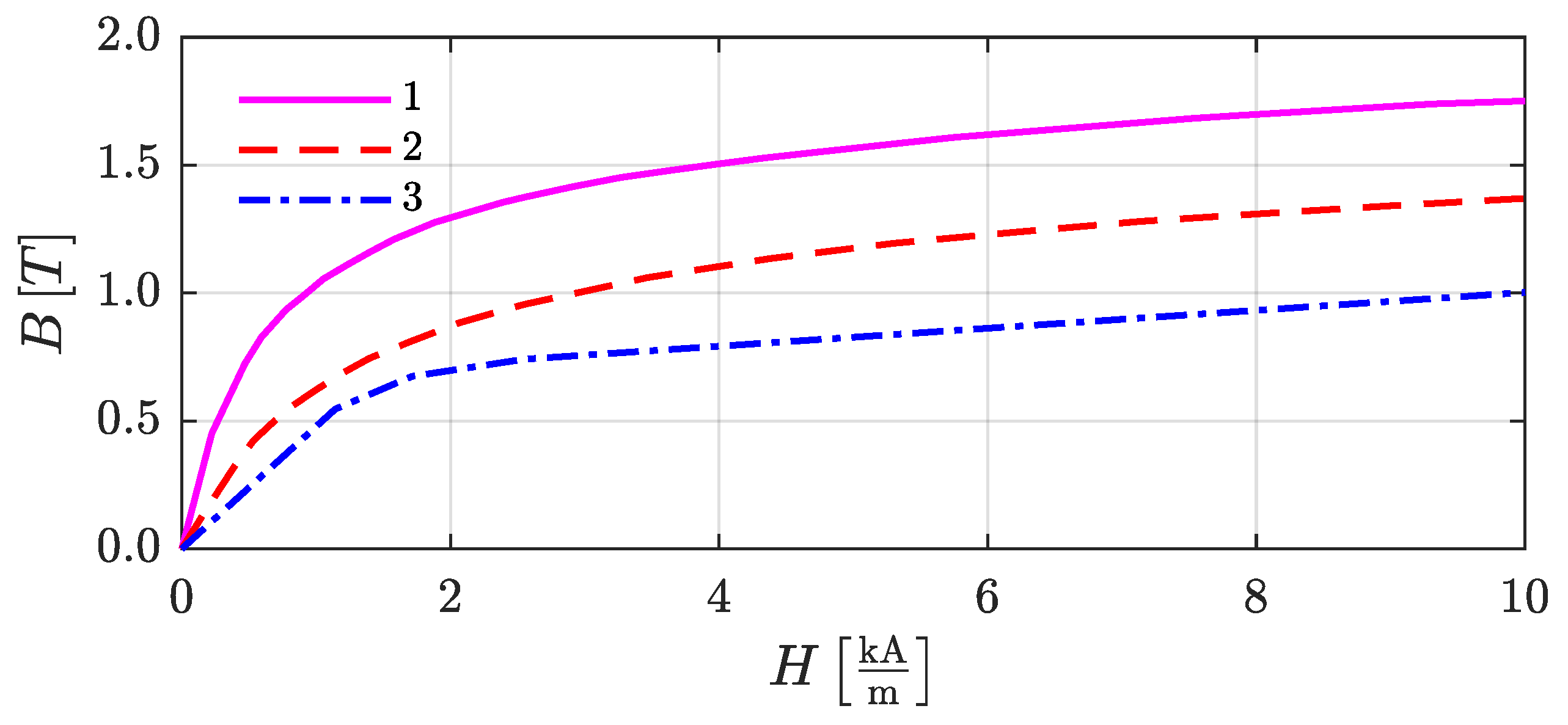
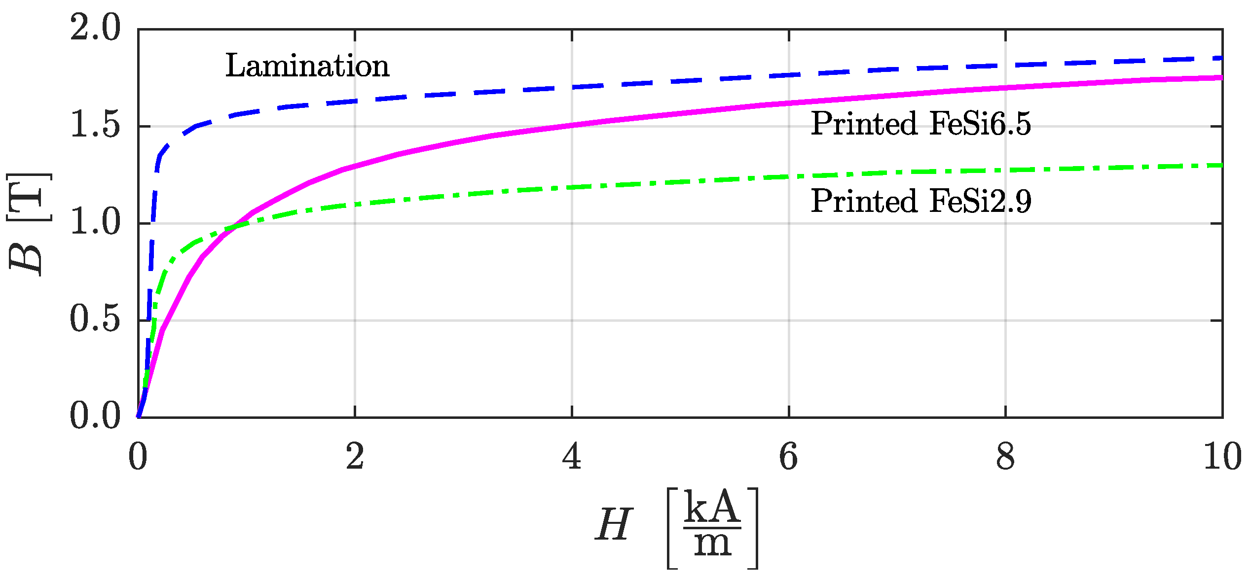
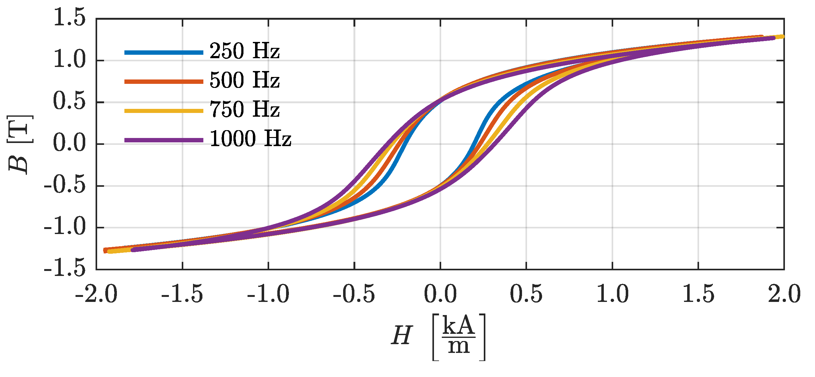
3.1. BH Curve
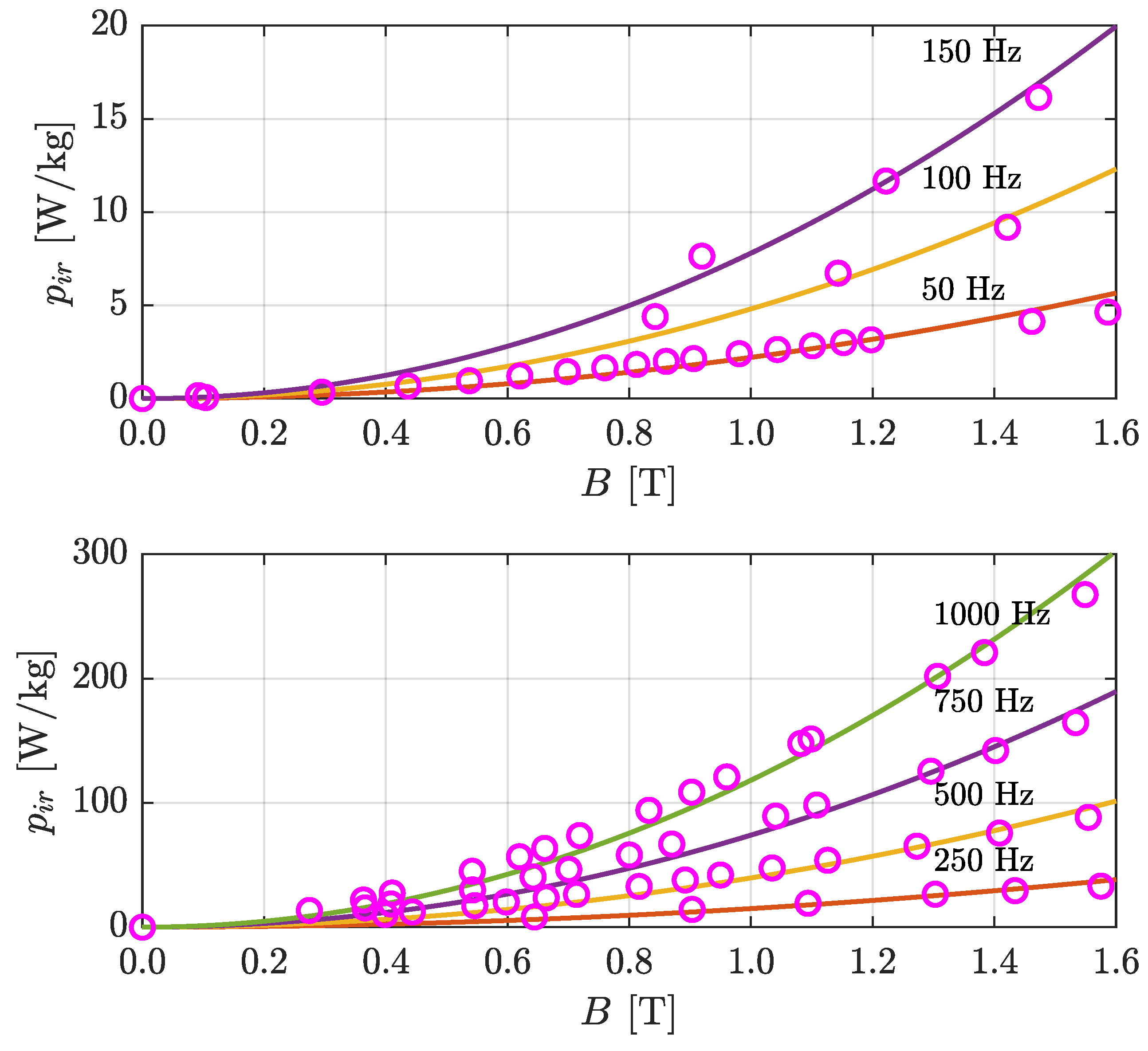
3.2. Power Losses
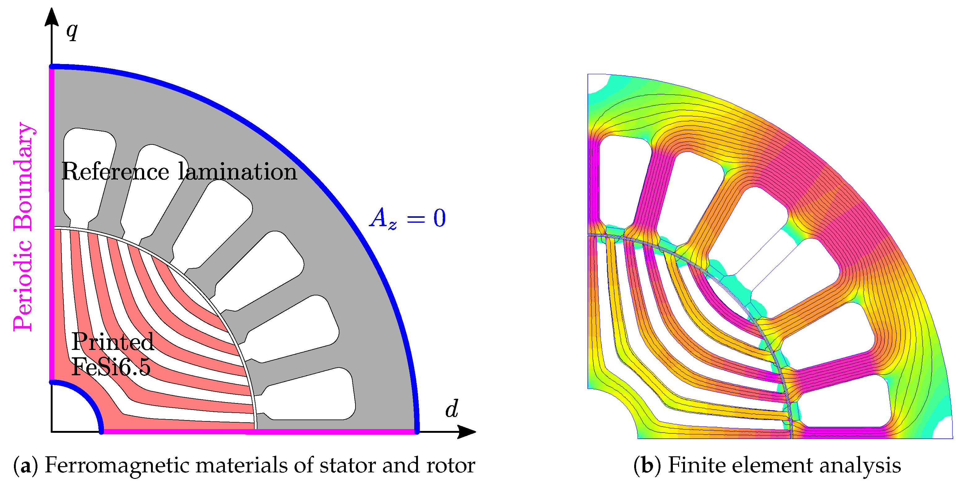
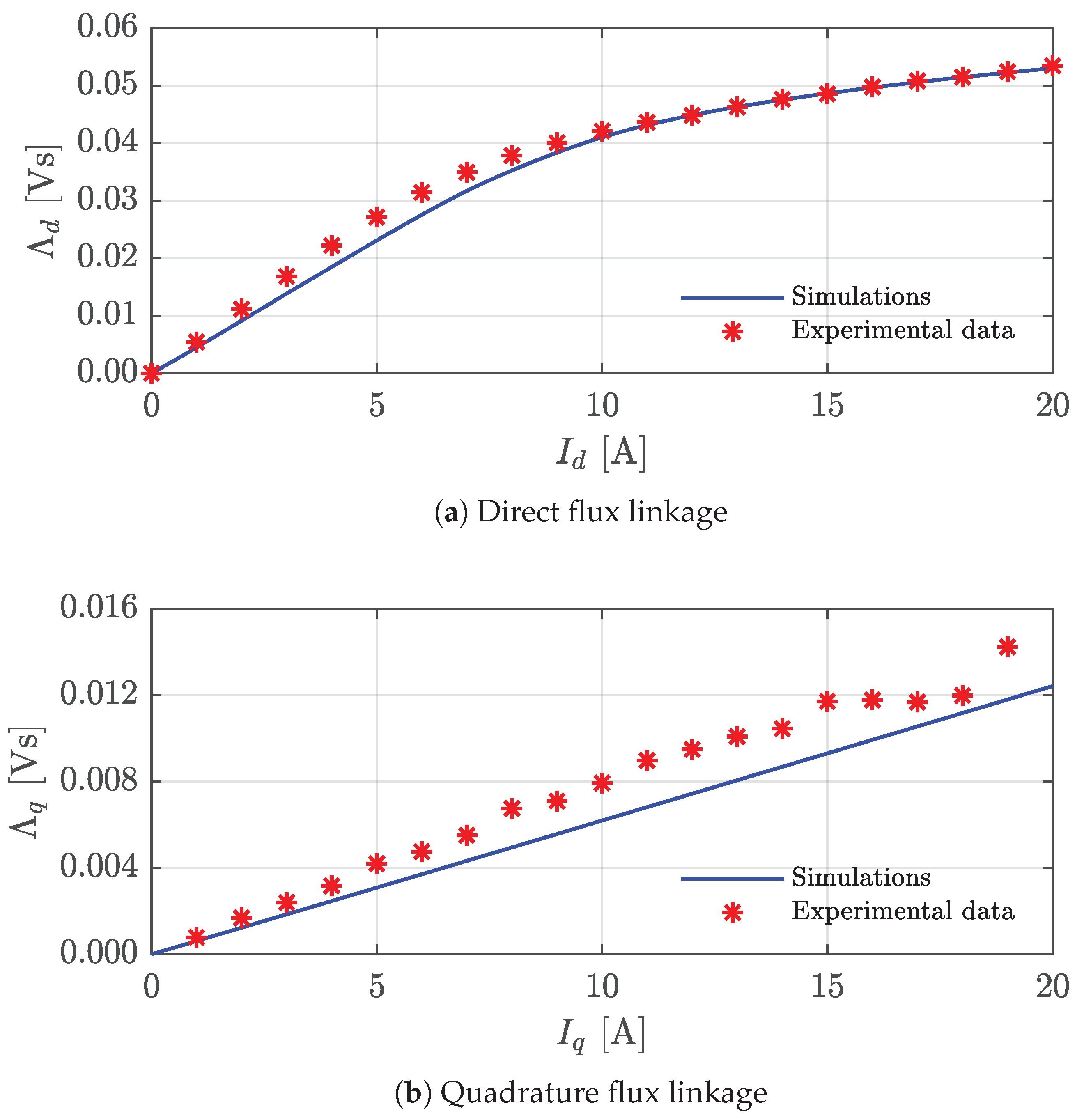
4. Application Example: Synchronous Reluctance Motor Magnetic Characteristic
5. Conclusions
Author Contributions
Funding
Data Availability Statement
Conflicts of Interest
References
- Lindzen, R.S. Climate Dynamics and Global Change. Annu. Rev. Fluid Mech. 1994, 26, 353–378. [Google Scholar] [CrossRef]
- Drouet, L.; Bosetti, V.; Padoan, S.A.; Aleluia Reis, L.; Bertram, C.; Dalla Longa, F.; Després, J.; Emmerling, J.; Fosse, F.; Fragkiadakis, K.; et al. Net zero-emission pathways reduce the physical and economic risks of climate change. Nat. Clim. Chang. 2021, 11, 1070–1076. [Google Scholar] [CrossRef]
- Davis, S.J.; Lewis, N.S.; Shaner, M.; Aggarwal, S.; Arent, D.; Azevedo, I.L.; Benson, S.M.; Bradley, T.; Brouwer, J.; Chiang, Y.M.; et al. Net-zero emissions energy systems. Science 2018, 360, eaas9793. [Google Scholar] [CrossRef] [PubMed]
- Fankhauser, S.; Smith, S.M.; Allen, M.; Axelsson, K.; Hale, T.; Hepburn, C.; Kendall, J.M.; Khosla, R.; Lezaun, J.; Mitchell-Larson, E.; et al. The meaning of net zero and how to get it right. Nat. Clim. Chang. 2021, 12, 15–21. [Google Scholar] [CrossRef]
- Azevedo, I.; Bataille, C.; Bistline, J.; Clarke, L.; Davis, S. Net-zero emissions energy systems: What we know and do not know. Energy Clim. Chang. 2021, 2, 100049. [Google Scholar] [CrossRef]
- Wong, K.V.; Hernandez, A. A Review of Additive Manufacturing. ISRN Mech. Eng. 2012, 2012, 208760. [Google Scholar] [CrossRef]
- Frazier, W.E. Metal Additive Manufacturing: A Review. J. Mater. Eng. Perform. 2014, 23, 1917–1928. [Google Scholar] [CrossRef]
- Bourell, D.L. Perspectives on Additive Manufacturing. Annu. Rev. Mater. Res. 2016, 46, 1–18. [Google Scholar] [CrossRef]
- Kim, H.; Lin, Y.; Tseng, T.L.B. A review on quality control in additive manufacturing. Rapid Prototyp. J. 2018, 24, 645–669. [Google Scholar] [CrossRef]
- Chen, Z.; Han, C.; Gao, M.; Kandukuri, S.Y.; Zhou, K. A review on qualification and certification for metal additive manufacturing. Virtual Phys. Prototyp. 2021, 17, 382–405. [Google Scholar] [CrossRef]
- Hasanov, S.; Alkunte, S.; Rajeshirke, M.; Gupta, A.; Huseynov, O.; Fidan, I.; Alifui-Segbaya, F.; Rennie, A. Review on Additive Manufacturing of Multi-Material Parts: Progress and Challenges. J. Manuf. Mater. Process. 2021, 6, 4. [Google Scholar] [CrossRef]
- Vafadar, A.; Guzzomi, F.; Rassau, A.; Hayward, K. Advances in Metal Additive Manufacturing: A Review of Common Processes, Industrial Applications, and Current Challenges. Appl. Sci. 2021, 11, 1213. [Google Scholar] [CrossRef]
- Mhetre, G.N.; Jadhav, V.S.; Deshmukh, S.P.; Thakar, C.M. A Review on Additive Manufacturing Technology. ECS Trans. 2022, 107, 15355–15374. [Google Scholar] [CrossRef]
- Wu, Y.; Lu, Y.; Zhao, M.; Bosiakov, S.; Li, L. A Critical Review of Additive Manufacturing Techniques and Associated Biomaterials Used in Bone Tissue Engineering. Polymers 2022, 14, 2117. [Google Scholar] [CrossRef]
- Srivastava, M.; Rathee, S.; Patel, V.; Kumar, A.; Koppad, P.G. A review of various materials for additive manufacturing: Recent trends and processing issues. J. Mater. Res. Technol. 2022, 21, 2612–2641. [Google Scholar] [CrossRef]
- Druzgalski, C.; Ashby, A.; Guss, G.; King, W.; Roehling, T.; Matthews, M. Process optimization of complex geometries using feed forward control for laser powder bed fusion additive manufacturing. Addit. Manuf. 2020, 34, 101169. [Google Scholar] [CrossRef]
- Colosimo, B.M.; Grasso, M.; Garghetti, F.; Rossi, B. Complex geometries in additive manufacturing: A new solution for lattice structure modeling and monitoring. J. Qual. Technol. 2021, 54, 392–414. [Google Scholar] [CrossRef]
- AM, M. Airbus Helicopters Begins High-Volume Metal Additive Manufacturing of A350 Components. Available online: https://www.metal-am.com/airbus-helicopters-begins-large-scale-metal-additive-manufacturing-of-a350-components/ (accessed on 9 January 2024).
- Metal, A.M. Boeing 777X Takes Flight with Reported 300 Additively Manufactured Parts in Each GE9X Engine. Available online: https://www.metal-am.com/boeing-777x-takes-flight-with-reported-300-additively-manufactured-parts-in-each-ge9x-engine/ (accessed on 9 January 2024).
- Simpson, N.; Mellor, P.H. Additive manufacturing of shaped profile windings for minimal AC loss in gapped inductors. In Proceedings of the 2017 IEEE International Electric Machines and Drives Conference (IEMDC), Miami, FL, USA, 21–24 May 2017. [Google Scholar] [CrossRef]
- Wohlers, C.; Juris, P.; Kabelac, S.; Ponick, B. Design and direct liquid cooling of tooth-coil windings. Electr. Eng. 2018, 100, 2299–2308. [Google Scholar] [CrossRef]
- Simpson, N.; North, D.J.; Collins, S.M.; Mellor, P.H. Additive Manufacturing of Shaped Profile Windings for Minimal AC Loss in Electrical Machines. IEEE Trans. Ind. Appl. 2020, 56, 2510–2519. [Google Scholar] [CrossRef]
- Compton, B.G.; Kemp, J.W.; Novikov, T.V.; Pack, R.C.; Nlebedim, C.I.; Duty, C.E.; Rios, O.; Paranthaman, M.P. Direct-write 3D printing of NdFeB bonded magnets. Mater. Manuf. Process. 2016, 33, 109–113. [Google Scholar] [CrossRef]
- Paranthaman, M.P.; Shafer, C.S.; Elliott, A.M.; Siddel, D.H.; McGuire, M.A.; Springfield, R.M.; Martin, J.; Fredette, R.; Ormerod, J. Binder Jetting: A Novel NdFeB Bonded Magnet Fabrication Process. JOM 2016, 68, 1978–1982. [Google Scholar] [CrossRef]
- Urban, N.; Huber, F.; Franke, J. Influences of process parameters on rare earth magnets produced by laser beam melting. In Proceedings of the 2017 7th International Electric Drives Production Conference (EDPC), Wuerzburg, Germany, 5–6 December 2017. [Google Scholar] [CrossRef]
- Pham, T.; Kwon, P.; Foster, S. Additive Manufacturing and Topology Optimization of Magnetic Materials for Electrical Machines—A Review. Energies 2021, 14, 283. [Google Scholar] [CrossRef]
- Tate, J.; Richardson, B.; Love, L. Additive Manufacturing for Low Volume Bearings; USDOE Office of Energy Efficiency and Renewable Energy: Washington, DC, USA, 2017. [CrossRef]
- Wrobel, R.; Mecrow, B. A Comprehensive Review of Additive Manufacturing in Construction of Electrical Machines. IEEE Trans. Energy Convers. 2020, 35, 1054–1064. [Google Scholar] [CrossRef]
- Cavagnino, A.; Vaschetto, S.; Pošković, E.; Fortunato, A.; Liverani, E. Magnetic Behavior and Loss Assessment of Additively Manufactured Fe-Si alloys. In Proceedings of the 2023 IEEE International Electric Machines & Drives Conference (IEMDC), San Francisco, CA, USA, 15–18 May 2023; pp. 1–6. [Google Scholar] [CrossRef]
- Tiismus, H.; Kallaste, A.; Belahcen, A.; Tarraste, M.; Vaimann, T.; Rassõlkin, A.; Asad, B.; Shams Ghahfarokhi, P. AC Magnetic Loss Reduction of SLM Processed Fe-Si for Additive Manufacturing of Electrical Machines. Energies 2021, 14, 1241. [Google Scholar] [CrossRef]
- Pham, T.Q.; Do, T.T.; Kwon, P.; Foster, S.N. Additive Manufacturing of High Performance Ferromagnetic Materials. In Proceedings of the 2018 IEEE Energy Conversion Congress and Exposition (ECCE), Portland, OR, USA, 23–27 September 2018. [Google Scholar] [CrossRef]
- Tiismus, H.; Kallaste, A.; Belahcen, A.; Vaimann, T.; Rassõlkin, A.; Lukichev, D. Hysteresis Measurements and Numerical Losses Segregation of Additively Manufactured Silicon Steel for 3D Printing Electrical Machines. Appl. Sci. 2020, 10, 6515. [Google Scholar] [CrossRef]
- Goll, D.; Schuller, D.; Martinek, G.; Kunert, T.; Schurr, J.; Sinz, C.; Schubert, T.; Bernthaler, T.; Riegel, H.; Schneider, G. Additive manufacturing of soft magnetic materials and components. Addit. Manuf. 2019, 27, 428–439. [Google Scholar] [CrossRef]
- Quercio, M.; Galbusera, F.; Poskovic, E.; Franchini, F.; Ferraris, L.; Canova, A.; Gruosso, G.; Demir, A.G.; Previtali, B. Functional characterization of L-PBF produced FeSi2.9 Soft Magnetic Material. In Proceedings of the 2022 International Conference on Electrical Machines (ICEM), Valencia, Spain, 5–8 September 2022. [Google Scholar] [CrossRef]
- Tong, C. Introduction to Materials for Advanced Energy Systems; Springer International Publishing: Cham, Switzerland, 2019. [Google Scholar] [CrossRef]
- Lesuer, D.R.; Syn, C.K.; Sherby, O.D.; Wadsworth, J.; Lewandowski, J.J.; Hunt, W.H. Mechanical behaviour of laminated metal composites. Int. Mater. Rev. 1996, 41, 169–197. [Google Scholar] [CrossRef]
- Moses, A. Electrical steels: Past, present and future developments. IEEE Proc. A (Phys. Sci. Meas. Instrum. Manag. Educ.) 1990, 137, 233–245. [Google Scholar] [CrossRef]
- Bourchas, K.; Stening, A.; Soulard, J.; Broddefalk, A.; Lindenmo, M.; Dahlén, M.; Gyllensten, F. Influence of cutting and welding on magnetic properties of electrical steels. In Proceedings of the 2016 XXII International Conference on Electrical Machines (ICEM), Lausanne, Switzerland, 4–7 September 2016; pp. 1815–1821. [Google Scholar] [CrossRef]
- Michieletto, D.; Alberti, L. Design and Realization of a Synchronous Reluctance Motor with Printed Rotor. In Proceedings of the IECON 2022—48th Annual Conference of the IEEE Industrial Electronics Society, Brussels, Belgium, 17–20 October 2022. [Google Scholar] [CrossRef]
- Michieletto, D.; Alberti, L. A Scalable Analytical Model for Printed Multi-Barrier Reluctance Rotor. In Proceedings of the 2023 IEEE International Electric Machines & Drives Conference (IEMDC), San Francisco, CA, USA, 15–18 May 2023; pp. 1–7. [Google Scholar] [CrossRef]
- Michieletto, D.; Alberti, L. On the performance of PMAREL and REL Synchronous Motor Prototypes with Printed Rotor. In Proceedings of the 2023 IEEE Energy Conversion Congress and Exposition (ECCE), Nashville, TN, USA, 29 October–2 November 2023; pp. 3953–3958. [Google Scholar] [CrossRef]
- Gibson, I.; Rosen, D.; Stucker, B.; Khorasani, M. Additive Manufacturing Technologies; Springer: Cham, Switzerland, 2021. [Google Scholar]
- Hossain, M.S.; Gonzalez, J.A.; Hernandez, R.M.; Shuvo, M.A.I.; Mireles, J.; Choudhuri, A.; Lin, Y.; Wicker, R.B. Fabrication of smart parts using powder bed fusion additive manufacturing technology. Addit. Manuf. 2016, 10, 58–66. [Google Scholar] [CrossRef]
- Sun, S.; Brandt, M.; Easton, M. Powder bed fusion processes. In Laser Additive Manufacturing; Elsevier: Amsterdam, The Netherlands, 2017; pp. 55–77. [Google Scholar] [CrossRef]
- Sisma. MySint100 Datasheet. Available online: https://www.sisma.com/en/products/mysint100/ (accessed on 9 January 2024).
- Höganäs. Available online: https://www.hoganas.com/en/ (accessed on 9 January 2024).
- Arató, P.; Bóc, I.; Gróf, T. Effect of composition on the loss of non-oriented medium silicon electric steels. J. Magn. Magn. Mater. 1984, 41, 53–55. [Google Scholar] [CrossRef]
- Hou, C.K. Effect of silicon on the loss separation and permeability of laminated steels. J. Magn. Magn. Mater. 1996, 162, 280–290. [Google Scholar] [CrossRef]
- Shimanaka, H.; Ito, Y.; Matsumara, K.; Fukuda, B. Recent development of non-oriented electrical steel sheets. J. Magn. Magn. Mater. 1982, 26, 57–64. [Google Scholar] [CrossRef]
- Kan, T.; Ito, Y.; Shimanaka, H. Magnetic properties of roller-quenched high silicon steel ribbons. J. Magn. Magn. Mater. 1982, 26, 127–129. [Google Scholar] [CrossRef]
- Nikon. Nikon Metrology MCT225 Datasheet. Available online: https://industry.nikon.com/en-aom/wp-content/uploads/sites/20/2021/11/mct225-en.pdf (accessed on 9 January 2024).
- King, W.E.; Barth, H.D.; Castillo, V.M.; Gallegos, G.F.; Gibbs, J.W.; Hahn, D.E.; Kamath, C.; Rubenchik, A.M. Observation of keyhole-mode laser melting in laser powder-bed fusion additive manufacturing. J. Mater. Process. Technol. 2014, 214, 2915–2925. [Google Scholar] [CrossRef]
- Wang, L.; Zhang, Y.; Chia, H.Y.; Yan, W. Mechanism of keyhole pore formation in metal additive manufacturing. npj Comput. Mater. 2022, 8, 22. [Google Scholar] [CrossRef]
- Huang, Y.; Fleming, T.G.; Clark, S.J.; Marussi, S.; Fezzaa, K.; Thiyagalingam, J.; Leung, C.L.A.; Lee, P.D. Keyhole fluctuation and pore formation mechanisms during laser powder bed fusion additive manufacturing. Nat. Commun. 2022, 13, 1170. [Google Scholar] [CrossRef] [PubMed]
- Qu, M.; Guo, Q.; Escano, L.I.; Clark, S.J.; Fezzaa, K.; Chen, L. Mitigating keyhole pore formation by nanoparticles during laser powder bed fusion additive manufacturing. Addit. Manuf. Lett. 2022, 3, 100068. [Google Scholar] [CrossRef]
- Mukherjee, T.; Zuback, J.S.; De, A.; DebRoy, T. Printability of alloys for additive manufacturing. Sci. Rep. 2016, 6, 19717. [Google Scholar] [CrossRef]
- Mukherjee, T.; DebRoy, T. Mitigation of lack of fusion defects in powder bed fusion additive manufacturing. J. Manuf. Process. 2018, 36, 442–449. [Google Scholar] [CrossRef]
- Ning, J.; Wang, W.; Zamorano, B.; Liang, S.Y. Analytical modeling of lack-of-fusion porosity in metal additive manufacturing. Appl. Phys. A 2019, 125, 797. [Google Scholar] [CrossRef]
- Bustillos, J.; Kim, J.; Moridi, A. Exploiting lack of fusion defects for microstructural engineering in additive manufacturing. Addit. Manuf. 2021, 48, 102399. [Google Scholar] [CrossRef]
- Wits, W.W.; Carmignato, S.; Zanini, F.; Vaneker, T.H.J. Porosity testing methods for the quality assessment of selective laser melted parts. CIRP Ann.-Manuf. Technol. 2016, 65, 201–204. [Google Scholar] [CrossRef]
- Fiorillo, F. Characterization and Measurement of Magnetic Materials; Elsevier: Amsterdam, The Netherlands, 2004. [Google Scholar] [CrossRef]
- Voestalpine. Isovac 350-50A Datasheet. 01/2018 Last Updated. Available online: https://www.voestalpine.com/division_stahl/content/download/32782/347314/file/DB_isovac_350-50A_E_280715.pdf, (accessed on 9 January 2024).
- Meeker, D.; Bianchi, N.; Gyselinck, J.; Sabariego, R.; Alberti, L.; Pellegrino, G.; Cupertino, F. Electrical machine analysis using free software. In Proceedings of the 2017 IEEE Energy Conversion Congress and Exposition (ECCE), Cincinnati, OH, USA, 1–5 October 2017. [Google Scholar]

| Min. dimension | Max. dimension | Avg. dimension |
| 3.72 | 59.3 | 27.7 |
| D10 | D50 | D90 |
| 18.7 | 27.2 | 37.5 |
Disclaimer/Publisher’s Note: The statements, opinions and data contained in all publications are solely those of the individual author(s) and contributor(s) and not of MDPI and/or the editor(s). MDPI and/or the editor(s) disclaim responsibility for any injury to people or property resulting from any ideas, methods, instructions or products referred to in the content. |
© 2024 by the authors. Licensee MDPI, Basel, Switzerland. This article is an open access article distributed under the terms and conditions of the Creative Commons Attribution (CC BY) license (https://creativecommons.org/licenses/by/4.0/).
Share and Cite
Michieletto, D.; Alberti, L.; Zanini, F.; Carmignato, S. Electromagnetic Characterization of Silicon–Iron Additively Manufactured Cores for Electric Machines. Energies 2024, 17, 650. https://doi.org/10.3390/en17030650
Michieletto D, Alberti L, Zanini F, Carmignato S. Electromagnetic Characterization of Silicon–Iron Additively Manufactured Cores for Electric Machines. Energies. 2024; 17(3):650. https://doi.org/10.3390/en17030650
Chicago/Turabian StyleMichieletto, Daniele, Luigi Alberti, Filippo Zanini, and Simone Carmignato. 2024. "Electromagnetic Characterization of Silicon–Iron Additively Manufactured Cores for Electric Machines" Energies 17, no. 3: 650. https://doi.org/10.3390/en17030650
APA StyleMichieletto, D., Alberti, L., Zanini, F., & Carmignato, S. (2024). Electromagnetic Characterization of Silicon–Iron Additively Manufactured Cores for Electric Machines. Energies, 17(3), 650. https://doi.org/10.3390/en17030650