Abstract
A two-layer control strategy for the participation of multiple battery energy storage systems in the secondary frequency regulation of the grid is proposed to address the frequency fluctuation problem caused by the power dynamic imbalance between the power system and load when a large number of new energy sources are connected to the grid. A comprehensive allocation model based on area regulation requirement (ARR) signals and area control error (ACE) signals is proposed to obtain the total output of the secondary frequency modulation (FM) demand with a higher degree of adaptation when the FM units respond to the automatic generation control command, and the total output is reasonably allocated to each FM unit by using the two-layer control. Considering the dynamic fluctuation of the grid frequency, the fluctuation is dynamically suppressed in real-time by applying model predictive control to successfully forecast the frequency deviation while realizing the deviation-free correction in the frequency dynamic correction layer. The optimal power distribution of FM units based on the distributed control concept, as well as the power depth of each unit, are coordinated in the equalization control layer while keeping a decent battery charge level. Finally, in Matlab/Simulink, the proposed control approach is simulated and validated. The findings show that the suggested control approach can suppress frequency difference fluctuation, keep the battery charged, and reduce the unit’s FM loss.
1. Introduction
The increasing penetration of new energy [1,2,3] raises concerns about the uncertainty and instability of its regulation, which could pose serious risks to the power system’s long-term safety. This could lead to low grid inertia and weak damping, which would increase frequency variability during power outages. Additionally, the traditional units responsible for frequency regulation’s limited capacity to regulate effectively make them unsuitable for promoting the safety and stability of the power grid, which is one of the reasons why the grid’s ability to use new energy is being restricted [4,5].
When comparing the response rate of energy storage to automatic generation control (AGC) commands with that of traditional FM units, it is found that among the various types of energy storage, the rate of the battery energy storage system (BESS) is more than 60 times that of traditional FM units [6,7]. As a result, the use of energy storage battery systems for frequency regulation is a hot topic of research. Energy storage has a strong short-time power throughput capability, bi-directional regulation, and accurate tracking [8]. According to the literature [9], battery storage systems have a lot of promise for offering grid-assisted services. This also suggests control algorithms and appropriate corrective energy measures to enable the batteries used in FM services to continually maintain their level of charge within tolerances. To address the issue of uneven BESS power distribution during fast FM, a model predictive control strategy method taking the FM rate features into consideration is put forth in the literature [10]. Large-scale battery energy storage is a new kind of flexible market actor that can arbitrage the energy market and make money by offering primary FM services, according to the literature [11].
One of the study foci of energy storage involvement in grid secondary frequency regulation has been the allocation method of area regulation requirement (ARR) signals and area control error (ACE) signals when the unit reacts to the AGC command and determines the total FM demand output [12,13]. Traditional allocation approaches include time/frequency domain allocation and proportional allocation [14,15], but they have low adaptability and a poor ability to match system output to overall FM demand output. The control benefits of ACE and ARR signals are contrasted and examined in the literature [16] to evaluate the FM effect of the allocation mode in combination with the technical characteristics of FM units. The technique did not fully take into account the FM features of the signal before and after integration. Instead, the literature [17] separated the ACE signal into three types of regulation regions with distinct priorities and computed the overall FM demand output based on different priorities. According to the literature [18], the steady-state frequency deviation in the middle and late FM periods can be recovered by the ARR signal, whereas the transient frequency deviation in the pre-fast FM period can be recovered by the ACE signal. The literature [19] proposed the sensitivity over zero point as the criterion for two signal modes switching in the complex frequency domain and analyzed at the theoretical level that the ACE signal assignment is favorable to the transient deviation while the ARR signal assignment is favorable to the steady-state deviation.
The distribution of the FM demand’s total output is now split into two categories: the proportionate allocation based on the power supply’s Dynamic Available AGC (DAA) and allocation based on the FM signal’s frequency domain characteristics [20,21]. Both [20,21] split the FM signal into high-frequency and low-frequency components using low-pass filters. The high-frequency component is then picked up by the BESS to assist in quickly recovering the transient frequency difference, and the low-frequency component is picked up by the conventional unit to assist in recovering the steady-state frequency difference. However, this strategy ignores the battery’s state of charge (SOC), which could result in irreversible damage to the long-term operating battery damage. The literature [22] allocates the FM responsibility to the variability of the FM cost of different units, which will lead to the frequent output of traditional units in the actual FM process. The literature [23] uses the distributed control principle to allocate the power output of the units involved in frequency regulation based on the FM loss cost but lacks the constraint on the system frequency deviation, which can easily lead to a poor overall FM effect. Traditional linked grids’ AGC control technique often rests on the mutual non-interference principle [24,25,26,27]. In other words, rather than coordinating mutual support, each control region governs the load variation within its own boundaries. The classic AGC control strategy is a pure communication-based strategy (i.e., only power fluctuation information on the contact line is exchanged) from the standpoint of non-cooperative games [28]. This control strategy converges, at most, with a Nash equilibrium (NE), which is typically distinct from the Pareto optimal solution. Consequently, in the current circumstances, the traditional AGC-based control notion limits the collaboration of AGC regulation resources throughout regions, which, in turn, leads to a shortage or idleness in AGC regulation resources in some provinces. Previous research primarily implements multi-region AGC joint frequency regulation based on two concepts. The first is the error diversity interchange (ADI) approach of decentralized area control. A method based on the idea of ADI was proposed by the literature [29], which examined the variance of control error (ACE) in each area and the control error of the entire network. It was shown that, after accounting for the correlation of the deviations, the variance of control error in the entire network would be smaller than the sum of the variance of control error in each area. Joint control in each area can effectively reduce the demand for regulation resources in each area. By modeling the behavior of the AGC system on the assumption that one control region determines the behavior of the entire system, ref. [30] implements an enhanced ADI approach. A dynamic ACE concept based on ADI is put forth in [31] to lessen the effect that the interconnected grid’s outgoing DC and the lack of high-power units in each region have on grid frequency regulation. Nevertheless, even though the ADI-based approach can lower the network-wide demand for AGC FM resources, it is unable to achieve the ideal distribution of ACE. The distributed optimal AGC method is the alternative. Large, networked power systems with communication and spatial constraints are well suited for the distributed control technique [32]. The idea of an ideal AGC was introduced in [33]. It was based on optimization theory and primal-dual transformations. It demonstrated that the multi-region distributed optimal AGC could be realized by utilizing the developed corresponding AGC control strategy with the dynamic equations of the interconnected system. A distributed economic AGC algorithm based on [10] was implemented in [34]; however, it is not universal and can only realize multieconomic optimization of regional AGC. From the standpoint of cooperative game theory, ref. [35] introduced cooperative game AGC (CG-AGC) based on optimum AGC and showed that the optimal solution produced by this tactic is consistent with the relevant optimal scheduling issue. Additionally, to achieve CG-AGC, the conventional fixed frequency control mechanism is employed; however, research [36] demonstrates that this approach is not ideal. The distributed secondary frequency control problem for multi-area systems with DC linkages is covered in [37]. While the model predictive control method can better realize the coordinated control of AGCs in each region, the online computation is too large to meet the actual control requirements. Moreover, ref. [38] proposed a cooperative-based distributed optimal AGC control strategy for synchronous grids. In order to realize mutual support between regions and improve the frequency quality of the grid, multi-region AGC joint frequency regulation inevitably permits a moderate amount of deviation from the planned current and deviation from the planned power. However, the above works of the literature ignored the power support of the contact line’s constraints. Real-time dispatch relies heavily on AGC. The primary challenge in implementing multi-region AGC joint frequency regulation is how to maintain contact line security while each region is under control and operated within the current dispatch framework. At the same time, the need for regulation resources must be effectively reduced in order to achieve an improved economy. Multi-region AGC optimum joint FM is essentially a multi-region AGC optimal real-time scheduling problem, given the nature of the task. The power system multi-region economic scheduling problem and the multi-region AGC optimal real-time scheduling are similar in that the multi-region economic scheduling problem can be solved under the coordinated influence of this multiplier [39]. In the multi-region economic scheduling problem, the aggregated utility function of the neighboring regions is expressed mathematically as the Lagrange multiplier of the contact line’s power balance constraint. This multiplier provides the essential information for the multi-region economic scheduling problem.
The literature mentioned above can prove the feasibility and necessity of BESS in participating in grid FM and also consider the coordination of unit response to total FM demand and the reasonableness of FM unit responsibility allocation, but there are some shortcomings, and thus, improvements are needed: (1) The FM unit cannot precisely fit the entire FM demand, and the combination of ACE and ARR signal characteristics is absent from the current research on FM signal distribution methods. (2) The existing literature [17,18,19,20,21] primarily distributes FM unit capacity based on the power dynamic adjustable capacity ratio; however, the method of the current literature lacks a thorough consideration of the grid FM demand and the FM capacity of the unit, making it impossible to fully utilize the advantages of the two FM signals and, as a result, also making it impossible for the FM unit’s output to be flexibly allocated based on maintaining the load level. The scenario where multiple groups of energy storage are involved in secondary FM is not taken into account by most of the current literature. When multiple groups of BESS are involved in FM together, it is easy to cause the BESS with a larger FM capacity to be overcharged and overdischarged, which is not conducive to the long-term use of energy storage. It is possible to redistribute the FM output of multiple groups of energy storage and traditional units using the consistency algorithm and distributed control principle.
Based on this, this paper puts forward the multiple battery energy storage system to participate in the secondary frequency modulation control strategy of the power grid under the new power system. First of all, based on the regional secondary frequency modulation model of the new power system scenario, the total output instruction of the secondary frequency modulation under AGC is determined, and the comprehensive distribution mode based on the ARR signal and ACE signal is proposed so as to give full play to the advantages of the two frequency modulation signals and consider the secondary frequency modulation capability of the power grid under the new power system. Second, the dual signal mode adaptive dynamic switching mode proposed considers the frequency dynamic correction and power equilibrium distribution of the double control strategy, using the model prediction control dynamic suppression frequency differences based on the consumption rate of the total demand output equilibrium allocation to the FM unit to stabilize the battery charge level and reduce the unit frequency modulation loss. Finally, the simulation verifies the effectiveness of the proposed strategy.
2. Regional Grid Frequency Regulation Model with Multiple BESSs
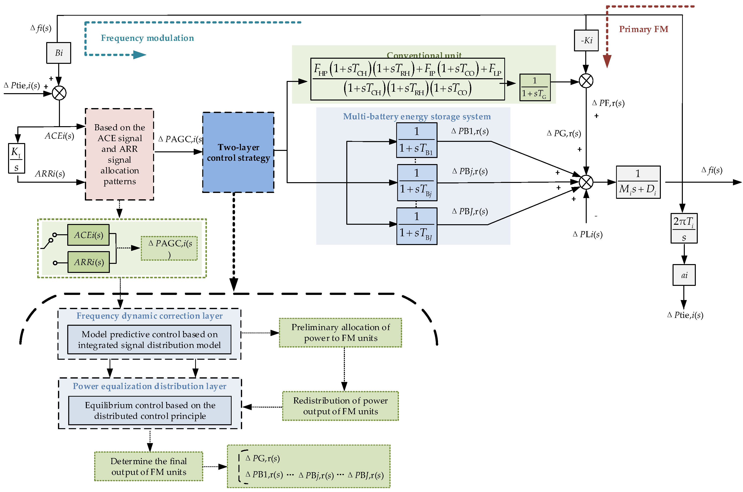
Based on the regional equivalence method to establish the regional grid frequency dynamic response model, the region is configured with 1 conventional unit and J BESS for frequency regulation, a total of 1 + J FM power sources. The input of the control system is the secondary FM demand output ΔPAGC,i(s), and the output is the active output of the FM unit. The dynamic response model of region i is shown in Figure 1 and the parameters in the model are defined as shown in Table 1 [40].

Figure 1.
Frequency dynamic response model of region i.

Table 1.
Definition of parameters in the model.
3. Distribution Model Based on ACE and ARR Signals
The signal assignment modes of BESS in response to AGC FM commands are area control demand (ARR) signal assignment-based and area control deviation (ACE) signal assignment-based, and the two signals can be converted by a PI controller. Based on the dynamic expressions of ACE and ARR signals in the literature [19], ΔPAGC,i(s) is introduced under the two signals as shown in Equations (1) and (2), respectively.
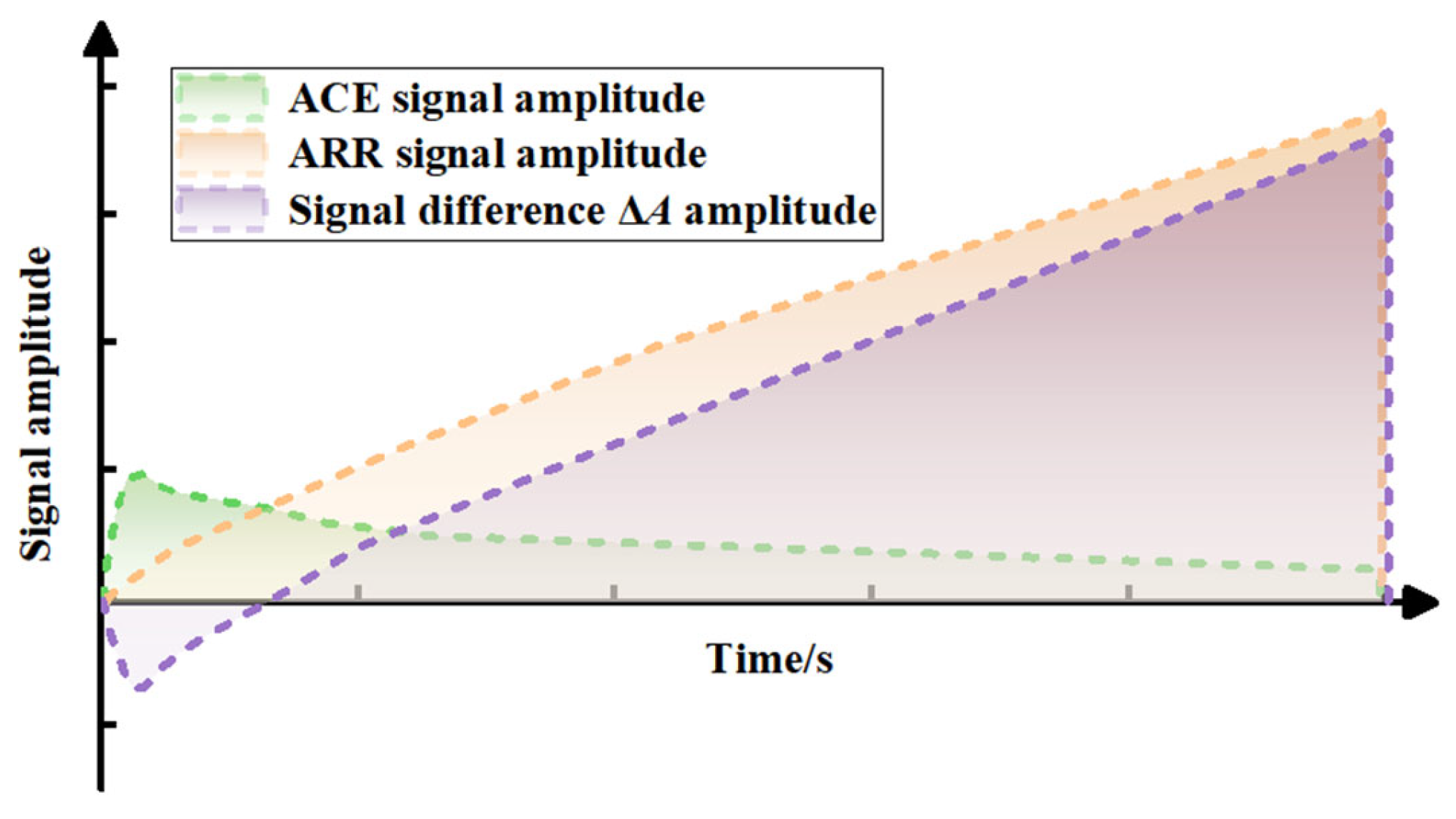
ΔA(s) is the difference between the ARR and ACE signals, and its expression is shown in Equation (3). The time domain curves of ACEi(s), ARRi(s), and ΔA are shown in Figure 2.

Figure 2.
Signal–time domain curve.
Whether the signal difference ΔA(s) crosses the zero point or not is used as the switching timing for the two modes.
- When ΔA(s) < 0
FM pre-frequency and ACE signal enhancement greater than the ARR signal is conducive to the system to quickly recover the transient frequency deviation, so take ACE control mode, the total demand out of the secondary FM ΔPAGC,i(s), as shown in Equation (1).
- When ΔA(s) > 0
In the middle and later stages of FM, the ACE signal weakens while the ARR signal is enhanced; at this time, the ACE signal plays a suppressive role in the later FM, and the ARR control is conducive to improving the steady-state frequency deviation of the system, so the ARR control mode is adopted, and the total demand out of the secondary FM ΔPAGC,i(s) is shown in Equation (2).
4. Two-Layer Control Strategy Based on FM Duty Assignment
4.1. Two-Tier Control Structure
For the allocation of the total demanded output ΔPAGC,i(s) of secondary frequency regulation when multiple BESS and conventional units participate in frequency regulation together, this paper takes into account the technical characteristics and economics of FM units and proposes a two-layer control strategy for multiple BESS and conventional units to respond to AGC commands in a coordinated manner based on meeting the demand of grid frequency regulation, and the structure diagram of the two-layer control is shown in Figure 3.
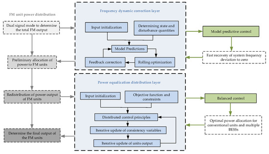
Figure 3.
Two-layer control structure in dual-signal mode.
The upper layer is the frequency dynamic correction layer that dynamically suppresses the frequency difference to zero, fully considering the actual working conditions of different FM units in response to AGC commands, using model predictive control to predict the correction of the frequency difference while making the preliminary allocation of the output of each FM unit obtain the expected output of each unit. The lower layer is the power balancing control layer, which achieves the optimal power distribution between conventional units and multiple storage batteries. The differences in technical characteristics of different FM units are fully considered, and the expected output of FM units obtained in the frequency dynamic correction layer is balanced and controlled based on the distributed control principle to finally determine the final output of each unit. The progressive optimization of the upper and lower control layers achieves the sustainable operation of multiple BESS and conventional units while satisfying the grid without differential frequency regulation.
4.2. Frequency Dynamic Correction Layer
In the combined allocation mode of both ARR and ACE signals, the first layer of the fuzzy controller takes the system frequency deviation Δf1 and the power signal PACE (or PARR) allocated to the FM unit in ACE (or ARR) mode as input quantities for the FM demand of the grid, thus determining the participation factor α for the energy storage response.
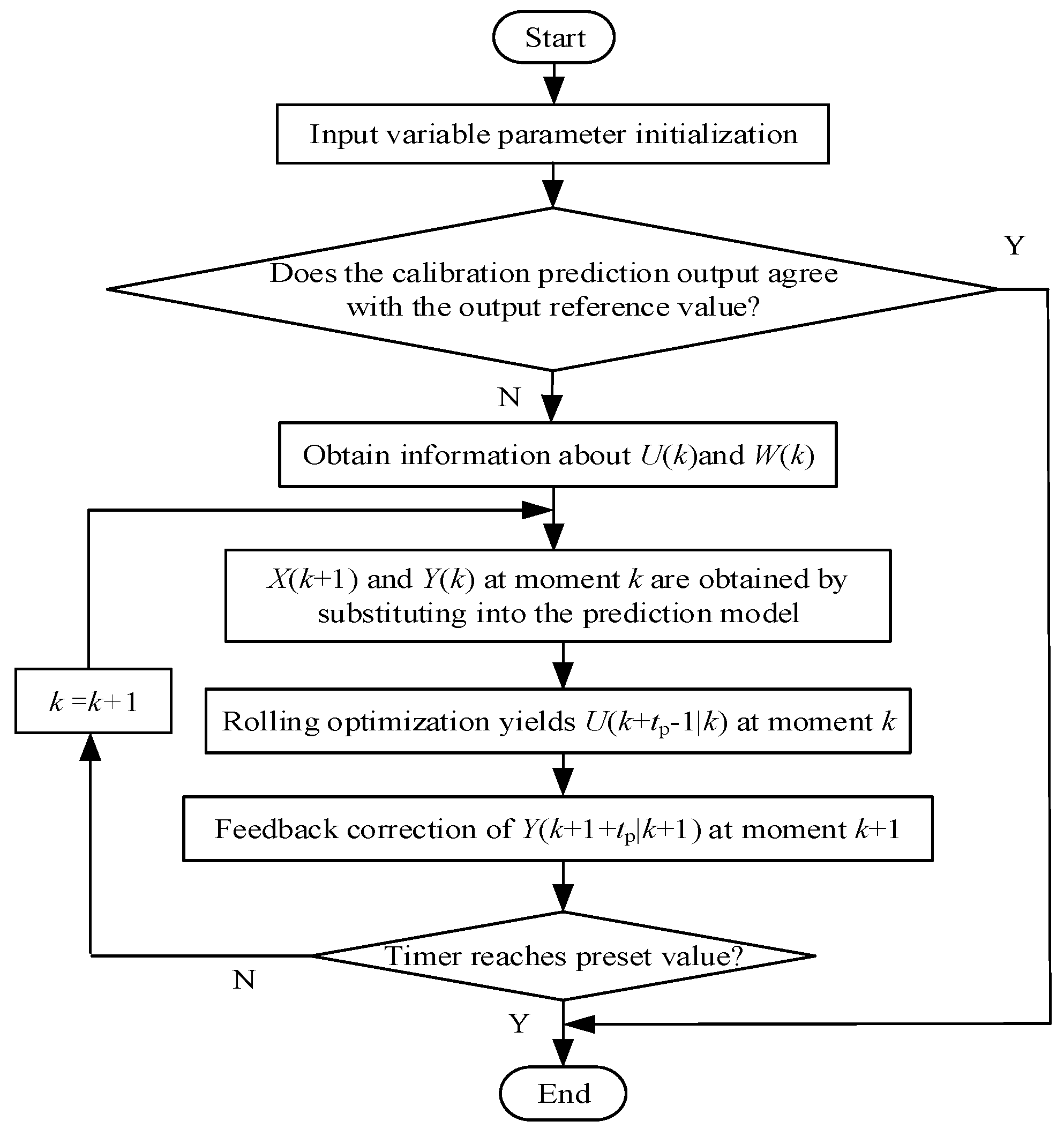
To correct the grid frequency deviation to zero by real-time prediction, model predictive control is used to dynamically suppress the frequency deviation while performing the initial allocation of power to each FM unit. The model predictive control algorithm generally consists of three parts: predictive model, rolling optimization, and feedback correction [41]. The principle is that the system state information of the previous moment is received, and then based on the predictive model of the system and the corresponding performance indicators, the optimal control sequence is solved and applied to the system; then, the rolling optimization is performed and the previous process is repeated. The principle of model predictive control is shown in Figure 4.
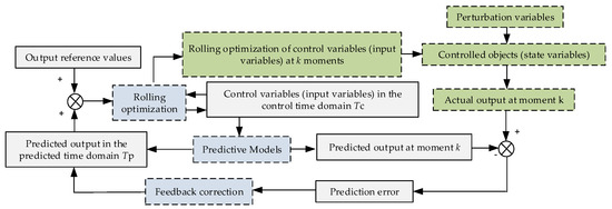
Figure 4.
Model predictive control structure diagram.
4.2.1. Model Predictions
A prediction model is built to analyze the historical states of system inputs and outputs, laying the foundation for realizing predictions of the control object’s output under different inputs.
The state space model of the frequency dynamic response at moment k is
where X(k), U(k), W(k), and Y(k) represent the state variables, input variables, disturbances, and outputs at moment k based on the settings in Figure 1, respectively, and A, B, R, and C represent the state matrix, input matrix, disturbance matrix, and output matrix of the system, respectively. The matrices can all be derived from the frequency dynamic response model of Figure 1 and are not repeated here. ΔP0G(k) and ΔP0Bj(k) denote the initialized inputs of the conventional unit and J energy storage units at the time of sampling at moment k. ΔY is the change of steam valve opening of the turbine.
After discretizing Equation (4) with Ts as the sampling period, the discrete state space model of the system at moment k is obtained as
4.2.2. Rolling Optimization
Based on the prediction model for the future output of the system, the change of the controlled object in the future moment is determined by minimizing the objective function. The objective function is
where Q and R are the output weighting matrix and control weighting matrix, respectively, Yr (k + tp|k) is the reference value of the output variables of the system at moment k for the future k + tp moment, and all the reference values of the output variables are set to 0. Y(k + tp|k) denotes the predicted output variables of the system at moment k for the future k + tc moment, where tp∈(1,Tp) and tp is the predicted time domain. U(k − 1 + tc|k) denotes the sequence of predicted optimal control variables of the system at moment k for the future k − 1 + tc moments, where tc∈(1,Tc), Tc is the control time domain, Umax and Umin are the upper and lower limits of the control variables of the system, and the upper and lower limits are set as the charging and discharging power constraints of the BESS.
The first column U(k) of U(k − 1 + tc|k) is applied to the system, and the optimization problem is updated and solved in the next period of time. The cycle advances continuously, thus achieving the purpose of rolling optimization.
4.2.3. Rolling Optimization
Feedback correction can reduce the deviation of the control system from the output prediction. After applying U(k) to the system at time k, the actual output of the system at time k + 1 can be measured as Ys(k + 1+tp|k + 1), and the predicted output Y(k + 1 + tp|k) and the actual output Ys(k + 1 + tp|k + 1) can be used to correct the predicted output at time k + 1 by weighting the actual output and the predicted error together.
The prediction error of the system at moment k is
The corrected predicted output of the system at moment k + 1 is
where H is the error correction weighting matrix.
4.2.4. MPC Implementation Frequency Dynamic Correction Process
Let the preset sampling interval of the timer be Δt1, and the flow of the k-moment MPC to achieve the dynamic correction of the grid frequency is as follow Figure 5.

Figure 5.
Flow chart of MPC to achieve dynamic correction of grid frequency.
4.3. Power Balancing Control Layer
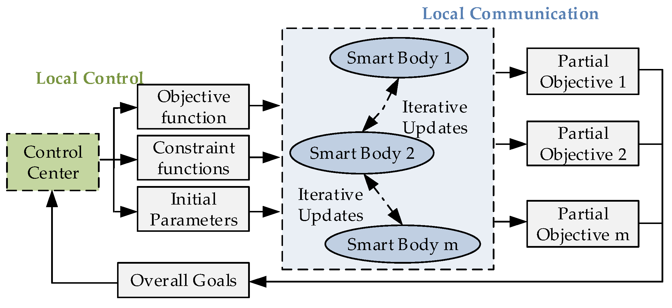
To achieve the optimal output allocation of conventional units and multiple BESS groups, the output results of the initial allocation are balanced and controlled based on the distributed control principle. The basic idea of power equalization control can be described as adjacent connected intelligences communicating with each other to achieve local goal consistency and then communicating signals to the control center to achieve overall goal consistency [40]. The power equalization control includes three parts: establishing the function, parameter initialization, and iterative update. The structure diagram of the equalization control is shown in Figure 6.
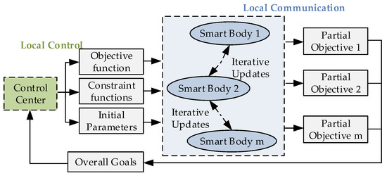
Figure 6.
Power balancing control structure diagram.
4.3.1. Objective Function and Constraint Function
Based on the demand of grid frequency regulation, the total power output of the FM units at the moment m needs to meet [42]
where PG,m is the FM output of the conventional unit at m moments, and PBj,m is the FM output of the BESS at m moments.
The FM loss is the change in operating cost brought about by the change in power output of the unit during the secondary FM process. The FM loss function of the conventional unit at m moments is
where DG,m is the FM loss of the conventional unit at moment m, aG is the weighting factor, RGmax and RGmin are the maximum and minimum values of the climbing rate of the conventional unit, PGmax,m and PGmin,m are the maximum and minimum values of the FM output of the conventional unit, and Δt2 is the timer preset sampling time interval.
The loss function of BESS consists of charge/discharge power and charge state, which can avoid the large FM loss of BESS when it assumes a large amplitude of steady-state frequency deviation. The FM loss function of each group of BESS at moment m is
where DG,m is the FM loss of BESS at moment m, aBj and bBj are the weighting coefficients, QSOCj,m is the charge state of BESS at moment m, QrefSOCj is the charge state of BESS at moment m, QrefSOCj is the expected reference value of BESS charge state during FM, QSOCjmax and QSOCjmin are the maximum and minimum values of BESS, RBjmax and RBjmin are the maximum and minimum values of the BESS climbing rate, and PBjmax,m and PBjmin,m are the maximum and minimum values of BESS FM output, respectively.
When PBj,m < 0, PBj,m = PcBj,m, BESS is the charging state, and when PBj,m > 0, PBj,m = PdBj,m, BESS is the discharging state. The charge state is further expressed as charging and discharging power by Equation (12), and finally, the BESS FM loss function shown in Equation (13) is obtained by combining Equation (11).
where QSOCj,m−1 is the charge state of BESS at m − 1 moment, and ηcj and ηdj are the BESS charging and discharging efficiency.
In summary, the power balance control objective function and its constraints are
4.3.2. Parameter Initialization
The consistency variable λ is the partial derivative of the loss function to the power output, and its magnitude can express the unit power cost of the FM unit. λ increases with the increase of the FM power output of the unit, and the consistency variable λ of each FM unit tends to be the same when the optimal power output distribution is achieved. λ is expressed as follows:
The result of FM unit output obtained from the frequency dynamic correction layer is used as the initial value of power balancing control, and the initial value of λ is obtained from Equation (15) as follows:
where P0Bj,m and P0G,m are the initial values of FM output for BESS and conventional units, respectively; λ0Bj,m and λ0G,m are the initial values of λ for BESS and conventional units, respectively; and PMPCBj,m and PMPCG,m are the output obtained from FM units using MPC.
4.3.3. Iterative Update
When iterating over λ, the unit changes its FM output so that its λ is approximately consistent with that of the adjacent power supply, thus achieving the purpose of power balancing control. Iterating over the FM unit α at m moments, the virtual consistency variable λn~α,m for the nth iteration is obtained by correcting λn−1α,m and unit output Pn−1α,m for the n − 1th iteration. The correction function is
where λn−1βd,m is the consistency variable of unit β adjacent to unit α, d∈[1,D], P0α,m is the initial value of unit α FM output, and σ1 and σ2 are correction factors.
If λn~α,m crosses the limit during the iteration, take the boundary value of its range as the actual consistency variable λnα,m. λnα,m for the nth iteration is
where λmax and λmin are the maximum and minimum values of the α consistency variable of the unit, respectively.
Substituting λnα,m into Equation (15) gives the theoretical output Pn~α,m of the FM unit, and using the same boundary value constraint gives the actual output Pnα,m as
where Pmax and Pmin are the maximum and minimum values of α FM output of the unit, respectively.
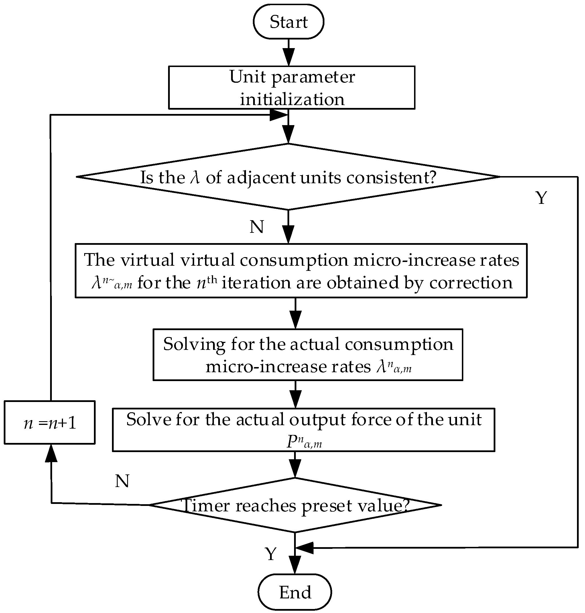
4.3.4. Power Balancing Control Process
Let the preset sampling time interval of the timer be Δt2. The process of realizing the power equilibrium distribution at time m in the n time iteration is shown in Figure 7.
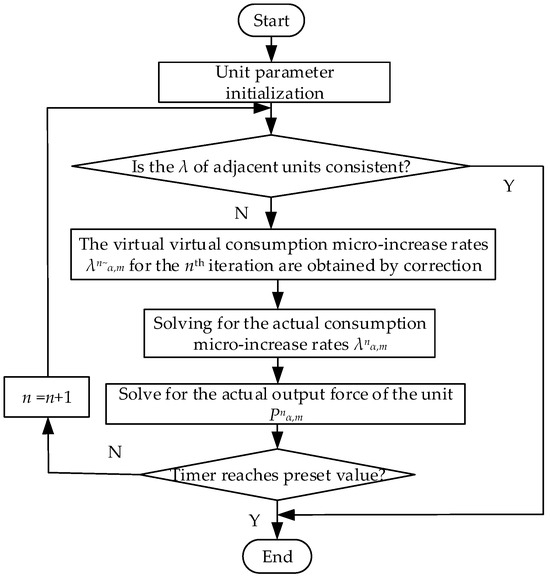
Figure 7.
Power balance distribution process chart.
5. Simulation Analysis
5.1. Simulation Parameters
The equivalent model of a typical regional power grid shown in Figure 1 is used to build a simulation in the Matlab/Simulink (version 2018) platform, and the maximum rated capacity of the unit and the rated frequency of 50 Hz are used as the reference values for the standardization. Two typical conditions of step disturbance and continuous disturbance are designed, and the effectiveness of this strategy (Scheme 3) is verified by comparing it with the dynamic frequency regulation capacity method (Scheme 2) and no energy storage (Scheme 1). The parameters of the FM unit are shown in Table 2 [42], and the system simulation parameters are shown in Table 1 [43].
Table 2.
FM unit parameters.
5.2. Step Perturbation
A step perturbation of ΔPLi of 0.01 is added in region i (rated at 100 MW). To better verify the effectiveness of the method in this paper based on the evaluation system, the variation curves of the frequency deviation, consistency variable, FM unit output, and battery charge state under the step perturbation of the three schemes are compared.
Figure 8a shows the frequency deviation variation curves of the system under step disturbance, and from the comparison curves of the three schemes, it can be obtained that all three schemes can adjust the frequency deviation without a difference, but compared with Scheme 1 and Scheme 2, Scheme 3 produces the smallest frequency deviation, and the frequency drop rate of Scheme 3 is 11.49% and 1.79% lower than that of Scheme 1 and Scheme 2, and the frequency recovery rate is 19.16% and 1.51% higher than that of Scheme 1 and Scheme 2 by 19.16% and 1.51%. Therefore, Scheme 3 can recover the frequency deviation to 0 in a shorter time, and at the same time, it can control the fluctuation of the frequency deviation in a smaller range during the recovery process.
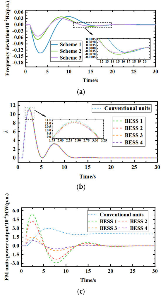
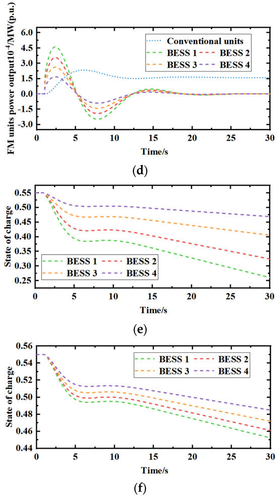
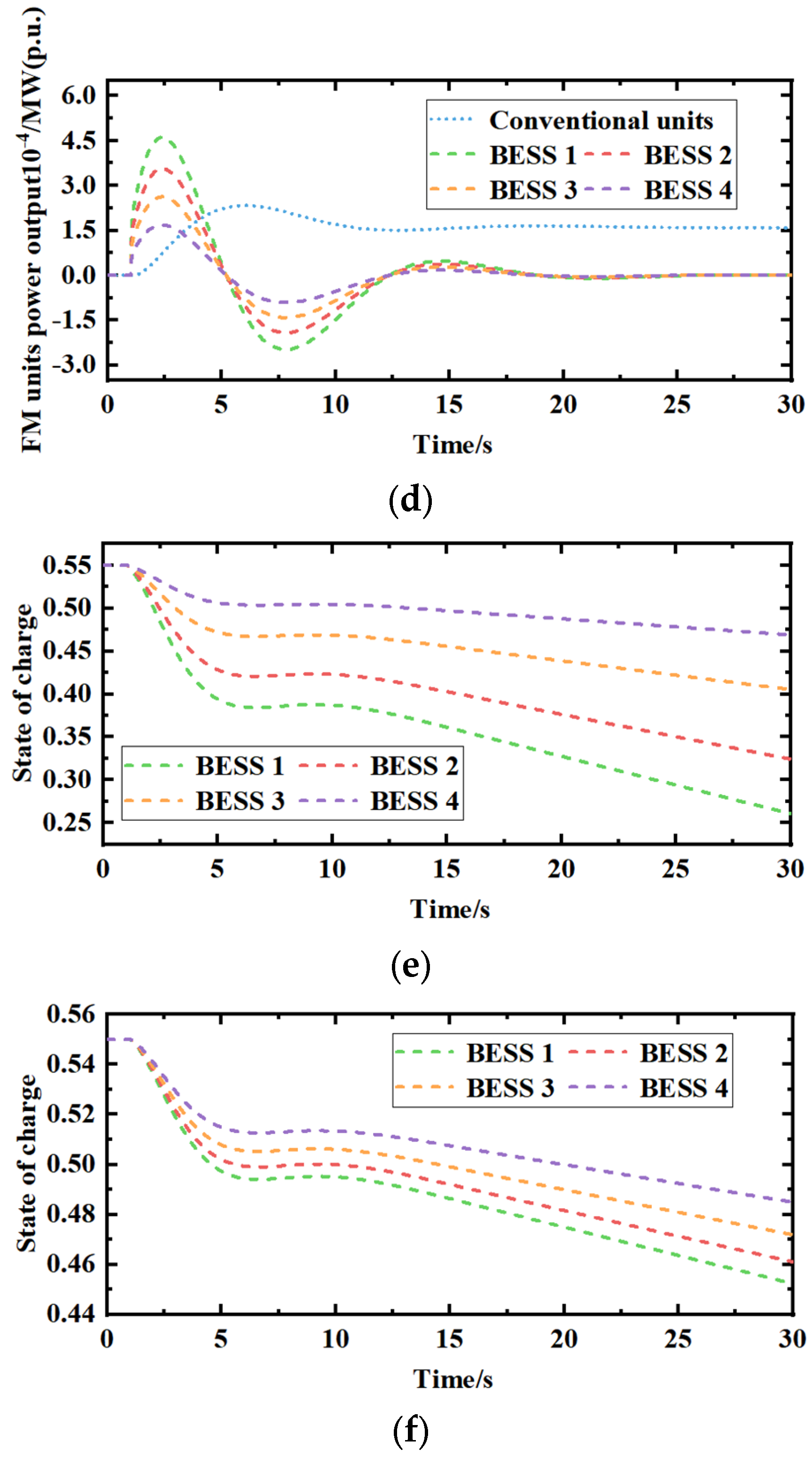
Figure 8.
(a). Frequency deviation comparison graph. (b). Variation of λ for FM units. (c). The output of FM units for Scheme 2. (d). The output of FM units for Scheme 3. (e). Battery charge state diagram for Scheme 2. (f). Battery charge state diagram for Scheme 3.
Figure 8b shows the consistency variable of FM units under Scheme 3, and Figure 8c,d show the output variation curves of FM units under Schemes 2 and 3, respectively. After adding the step disturbance, from Figure 8b–d, it can be obtained that (1) the high consistency of the consistency variable for each FM unit indicates that Scheme 3 has a good effect on the unit output balance control and (2) the BESS has a fast climbing rate and prioritizes the output, but the output varies due to the different FM capacities of each group of BESS, among which the capacity of BESS 1 is large and has more output, and the capacity of BESS 4 is small and has less output. Scheme 2 lacks the equalization control of the output of multiple groups of BESS; thus, the BESS with the large capacity is damaged due to taking too much output, and Scheme 3, after adding the equalization control, makes (3) the output of the conventional unit relatively smooth. Compared with Scheme 2, the output of the conventional unit in Scheme 3 is smoother after receiving the equalization control, which can effectively avoid the wear and tear caused by the fluctuation of its output.
Figure 8e,f show the charge state change curves of FM units under Scheme 2 and Scheme 3, respectively, and the initial charge state of each group of BESS is 0.55. From the figure, it can be obtained that the power output of each group of BESS in Scheme 2 is unbalanced, and the power output of BESS1 with a large capacity is too much, causing SOC to drop rapidly, while the power output of BESS 4 with a small capacity is less and SOC changes less, which may easily lead to the large-capacity BESS being overcharged and over-discharged, and the small capacity BESS is wasted. Compared with Scheme 2, the SOC variation of each group of BESS in Scheme 3 is balanced and less fluctuating, and it can stabilize the SOC variation in each group of BESS within 0.45~0.55. Comparing the average values of the charge states of Scheme 2 and Scheme 3 during operation, the maintenance level of the charge state of Scheme 3 is 66.6% higher than that of Scheme 2.
5.3. Continuous Perturbation
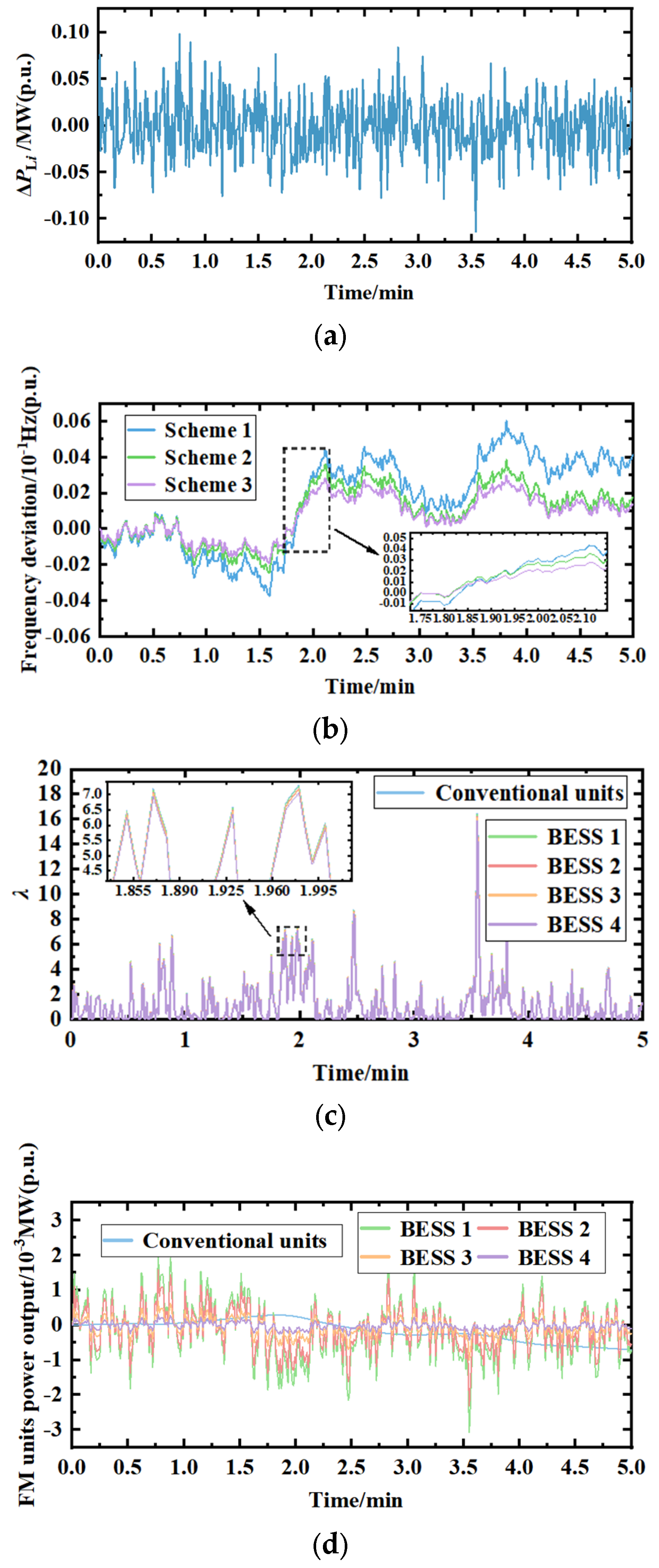
A 5 min continuous perturbation, as shown in Figure 9a, is added in region i (rated at 100 MW). To better verify the effectiveness of the method in this paper based on the evaluation system, the change curves of frequency deviation, consistency variable, FM unit output, and battery charge state under step perturbation of the three schemes are utilized for comparison.
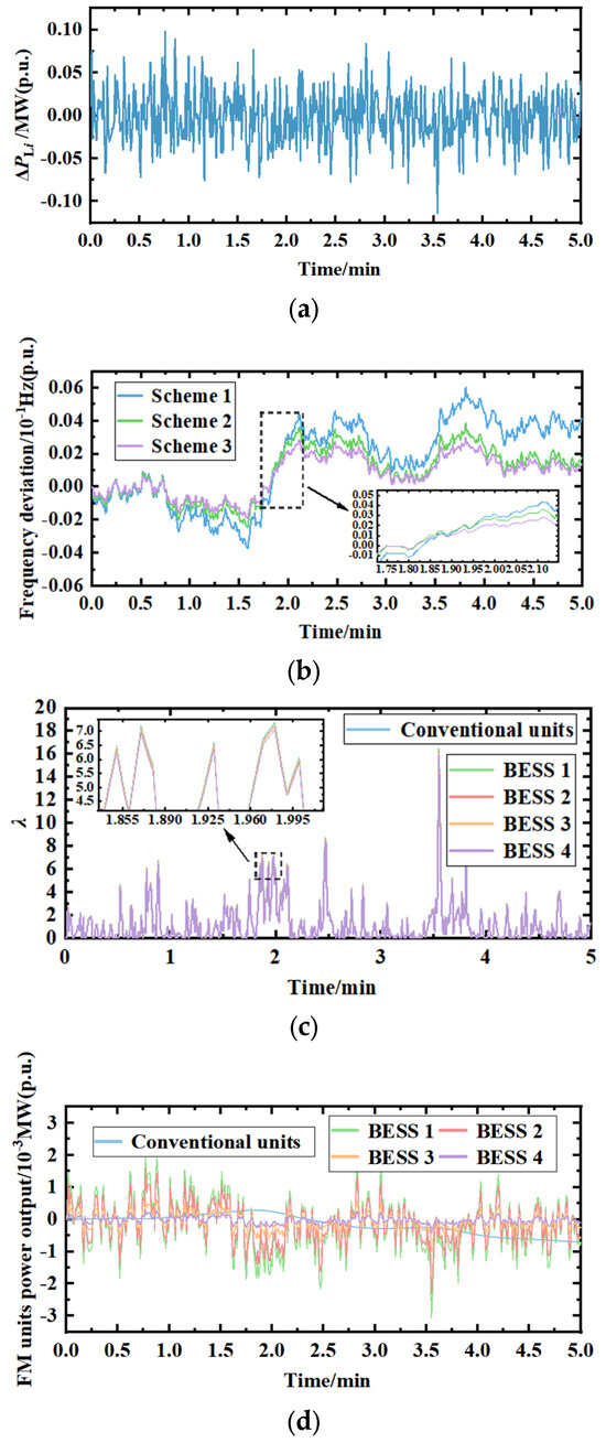
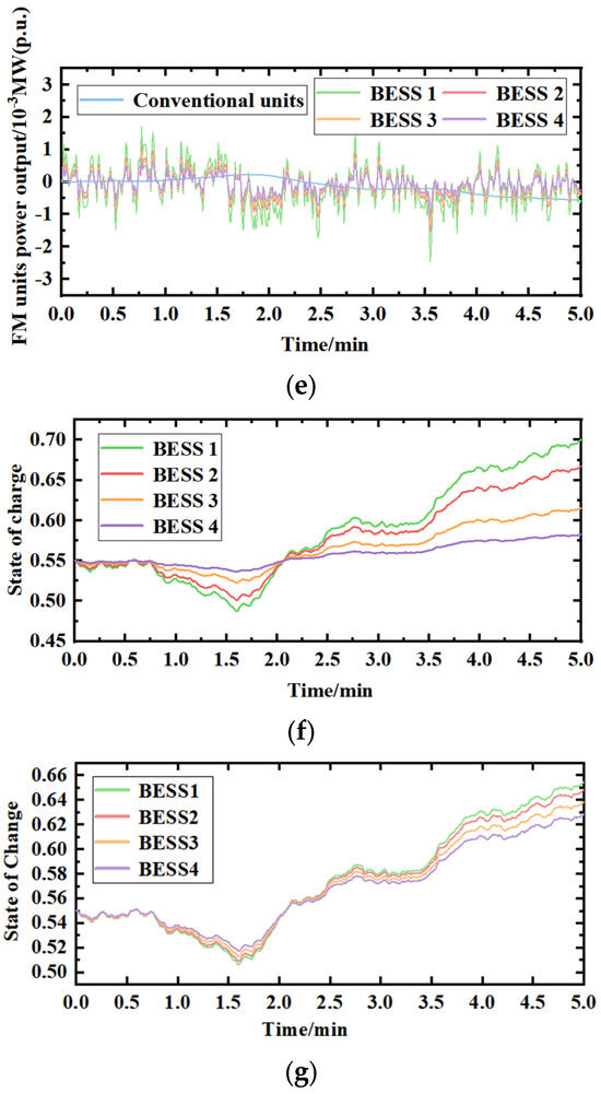
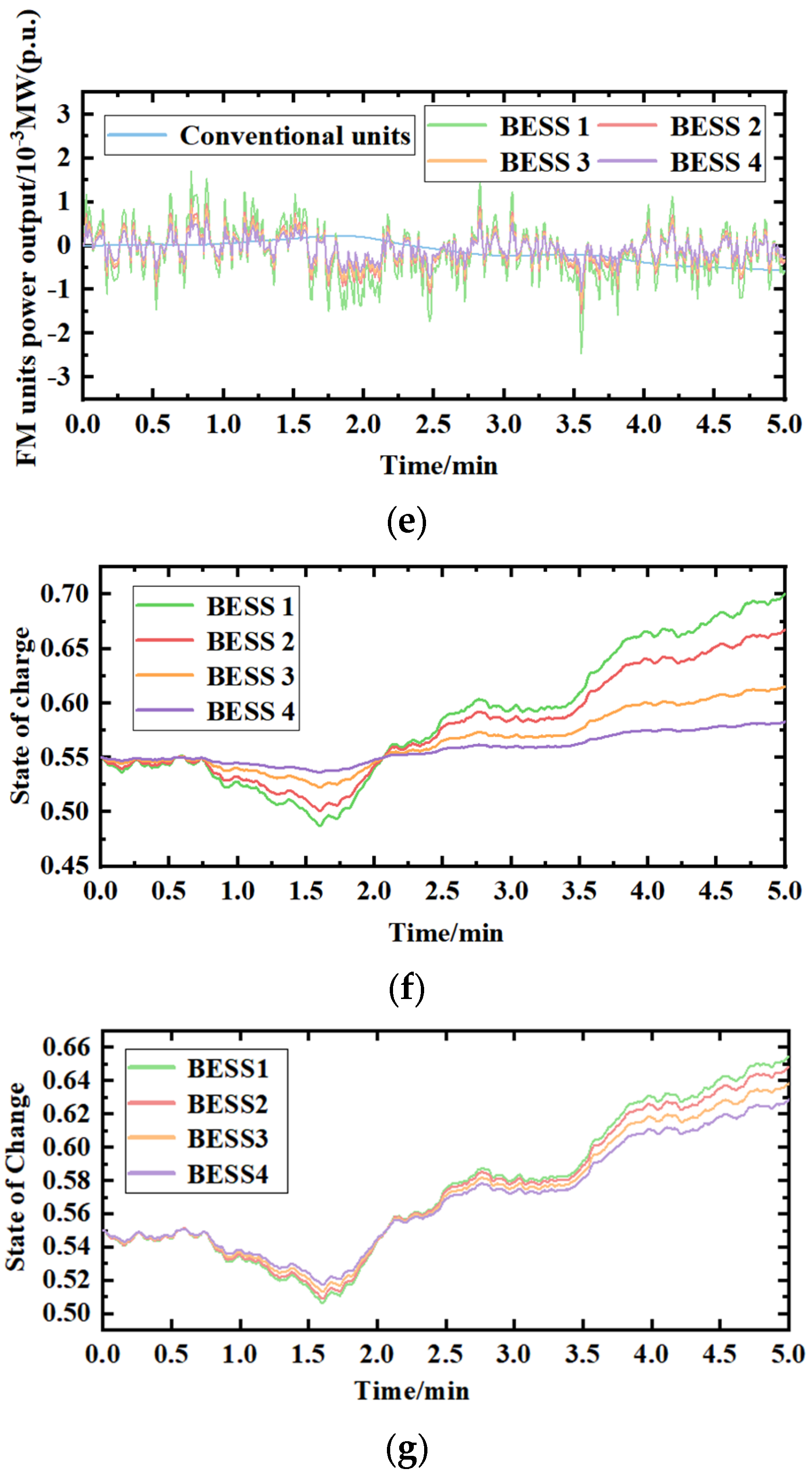
Figure 9.
(a). Continuous load perturbation. (b). Frequency deviation comparison graph. (c). Variation of λ for FM unit. (d). The output of FM units for Scheme 2. (e). The output of FM units for Scheme 3. (f). Battery charge state diagram for Scheme 2. (g). Battery charge state diagram for Scheme 3.
Figure 9b shows the frequency deviation variation curves of the system under continuous disturbance, and from the comparison curves of the three schemes, it can be obtained that the frequency deviation produced by Scheme 3 is the smallest, and the frequency drop rate of Scheme 3 is 8.87% and 1.55% lower than that of Schemes 1 and 2, and the frequency recovery rate is 9.50% and 1.97% higher than that of Schemes 1 and 2. In summary, Scheme 3 has better control of frequency deviation fluctuations.
Figure 9c shows the λ variation of the FM unit, and Figure 9d,e show the output variation curves of the FM unit under Scheme 2 and Scheme 3, respectively. After adding continuous disturbance, from Figure 9c–e, it can be obtained that (1) the approximate agreement of the consistency variable for each FM unit indicates that Scheme 3 has a good effect on the unit output balance control; (2) Scheme 2 lacks control of the output of multiple groups of Scheme 2 lacks balanced control of the output of multiple BESSs, and the output of each group of BESSs is seriously unbalanced, with the output of BESS 1 fluctuating more sharply and being more easily damaged, and the output of BESS 4 is too little, resulting in wasted resources. (3) Compared with Scheme 2, the conventional unit in Scheme 3 has a smoother output after receiving equalization control, which can effectively reduce mechanical wear and tear.
Figure 9f,g show the charge state change curves of FM units under Scheme 2 and Scheme 3, respectively, and the initial charge state of each group of BESS is 0.55. From the figure, we can obtain the following: the SOC changes of each group of BESS in Scheme 2 are relatively extreme, the SOC fluctuation of BESS 4 is too small, and the SOC fluctuation of BESS 1 is too large, which may easily reduce the life of large-capacity BESS in long-term use and easily cause the waste of small capacity BESS. Compared with Scheme 2, the SOC variation of each group of BESS in Scheme 3 is balanced and less fluctuating, and the SOC variation of each group of BESS can be stabilized within a certain range. Comparing the average values of the charge state during operation for Scheme 2 and Scheme 3, the maintenance level of the charge state for Scheme 3 is 47.2% higher than that of Scheme 2.
6. Conclusions
This paper proposes a multi-group battery energy storage system to participate in the new power system scenario. The dual signal allocation strategy in this strategy, through the timely conversion of two FM signals, can give full play to the advantages of the two frequency modulation signals and improve the matching degree of the system output response to the total demand of frequency modulation output. The frequency dynamic correction control of the upper layer control can predict and correct the power grid frequency difference in real time. When considering the actual working conditions of different FM units responding to the AGC instruction, the model prediction control is used to dynamically suppress the frequency difference. The power balance control of the lower level control can comprehensively consider the technical characteristics and economy of the FM unit. The equilibrium control of the upper predicted output is based on the principle of distributed control. Finally, the optimal output distribution of the FM unit is realized, and the final output of the FM unit is obtained. The simulation results show that the output situation and charge state of each group of BESS can be maintained at a good level compared with Scheme 2.
Based on the paper’s findings, a number of concerns pertaining to this subject require additional research. The inherent volatility of wind energy has led to a global boom in grid-connected wind power generation in recent years, and wind power has progressively become a critical component of capacity. To investigate the feasibility of altering the capacity in accordance with the wind power’s varying time period, more research into the wind power’s fluctuating characteristics is necessary. The internal control strategy of the power plant, the dispatch center’s control strategy, and the inter-regional coordination control strategy are all parts of the integrated control strategy, which is made up of a variety of control techniques and methodologies. Since the cooperation problem has not been thoroughly covered in this study, one area that needs more research is how to improve cooperation in this integrated control technique.
Author Contributions
Conceptualization, P.Z. and S.X.; methodology, P.Z.; software, Y.W.; validation, Q.X. and H.D.; formal analysis, C.C.; investigation, W.C.; resources, Y.W.; data curation, Q.X.; writing—original draft preparation, P.Z.; writing—review and editing, S.X. and Y.W.; visualization, P.Z.; supervision, H.D.; project administration, H.D.; funding acquisition, Y.W. and Q.X. All authors have read and agreed to the published version of the manuscript.
Funding
This research was funded by the Science and Technology Plan of State Grid Baiyin Power Supply Company, Gansu Province, China, grant number D23FZ2703007.
Data Availability Statement
Data are contained within the article.
Conflicts of Interest
Author Pan Zhang, Shijin Xin, Yunwen Wang and Qing Xu were employed by the State Grid Baiyin Power Supply Company, State Grid Gansu Power Company. Author Chunsheng Chen was employed by the State Grid Baiyin Pearl Power (Group) Co. The remaining authors declare that the research was conducted in the absence of any commercial or financial relationships that could be construed as a potential conflict of interest.
References
- Chen, W.; Sun, N.; Ma, Z.C.; Liu, W.F.; Dong, H.Y. A Two-Layer Optimization Strategy for Battery Energy Storage Systems to Achieve Primary Frequency Regulation of Power Grid. Energies 2023, 16, 2811. [Google Scholar] [CrossRef]
- Wu, Z.; Gao, D.W.; Zhang, H.; Yan, S.; Wang, X. Coordinated Control Strategy of Battery Energy Storage System and PMSG-WTG to Enhance System Frequency Regulation Capability. IEEE Trans. Sustain. Energy 2017, 8, 1330–1343. [Google Scholar] [CrossRef]
- Tang, R.; Yang, J.; Yang, W. Stability of Frequency Regulation of Pumped-Storage Plants with Multiple Units Sharing Common Penstock and Busbar. IOP Conf. Ser. Earth Environ. Sci. 2018, 163, 012094. [Google Scholar] [CrossRef]
- Nema, S.; Prakash, V.; Pandžić, H. Adaptive Synthetic Inertia Control Framework for Distributed Energy Resources in Low-Inertia Microgrid. IEEE Access 2022, 10, 54969–54979. [Google Scholar] [CrossRef]
- Nema, S.; Prakash, V.; Pandžić, H. Coordinated Synthetic Inertia Control Provision from Distributed Energy Resources and Energy Storage Systems. In Proceedings of the 2022 International Conference on Intelligent Controller and Computing for Smart Power (ICICCSP), Hyderabad, India, 21–23 July 2022; pp. 1–5. [Google Scholar]
- Lee, J.; Kim, J.M.; Yi, J.; Won, C.Y. Battery Management System Algorithm for Energy Storage Systems Considering Battery Efficiency. Electronics 2021, 10, 1859. [Google Scholar] [CrossRef]
- Wang, K.; Qiao, Y.; Xie, L.; Li, J.; Lu, Z.; Yang, H. A Fuzzy Hierarchical Strategy for Improving Frequency Regulation of Battery Energy Storage System. J. Mod. Power Syst. Clean Energy 2021, 9, 689–698. [Google Scholar] [CrossRef]
- You, J.; Jiang, T. Power Regulation Strategy of Virtual Pumped Storage Power Station Based on Compressed Air Energy Storage. IOP Conf. Ser. Mater. Sci. Eng. 2019, 677, 032030. [Google Scholar] [CrossRef]
- Hollinger, R.; Diazgranados, L.M.; Wittwer, C.; Engel, B. Optimal Provision of Primary Frequency Control with Battery Systems by Exploiting All Degrees of Freedom within Regulation. Energy Procedia 2016, 99, 204–214. [Google Scholar] [CrossRef]
- Subroto, R.K.; Lian, K.L.; Chu, C.-C.; Liao, C.-J. A fast frequency control based on model predictive control taking into account of optimal allocation of power from the energy storage system. IEEE Trans. Power Del. 2021, 36, 2467–2478. [Google Scholar] [CrossRef]
- Xia, W.; Liming, Y.; Kerui, W.; Shaoping, L. Bi-level non-convex joint optimization model of energy storage in energy and primary frequency regulation markets. Int. J. Electr. Power Energy Syst. 2021, 134, 107408. [Google Scholar]
- Tang, Y.; Yang, C.; Yan, Z.; Xue, Y.; He, Y. Coordinated Control of a Wind Turbine and Battery Storage System in Providing Fast-Frequency Regulation and Extending the Cycle Life of Battery. Front. Energy Res. 2022, 10, 927453. [Google Scholar] [CrossRef]
- Li, C.; Li, P.; Yu, H.; Li, H.; Zhao, J.; Li, S.; Wang, C. Optimal Planning of Community Integrated Energy Station Considering Frequency Regulation Service. J. Mod. Power Syst. Clean Energy 2021, 9, 264–273. [Google Scholar] [CrossRef]
- Jin, C.; Lu, N.; Lu, S.; Makarov, Y.V.; Dougal, R.A. A Coordinating Algorithm for Dispatching Regulation Services between Slow and Fast Power Regulating Resources. IEEE Trans. Smart Grid. 2014, 5, 1043–1050. [Google Scholar]
- Punyakaew, S.; Parnichkun, M. Vibration Energy Harvesting for Low Frequency Using Auto-Tuning Parametric Rolling Pendulum under Exogenous Multi-Frequency Excitations. Theor. Appl. Mech. Lett. 2020, 10, 448–455. [Google Scholar] [CrossRef]
- Cheng, Y.; Tabrizi, M.; Sahni, M.; Povedano, A.; Nichols, D. Dynamic Available AGC Based Approach for Enhancing Utility Scale Energy Storage Performance. IEEE Trans. Smart Grid 2014, 5, 1070–1078. [Google Scholar] [CrossRef]
- Lv, L.X.; Chen, S.H.; Zhang, X.B.; Pang, T.; Huang, C.X. A secondary frequency control strategy for power system considering the consistency of scaled battery energy storage. Thermoelectr. Power Gener. 2021, 50, 108–117. [Google Scholar]
- Zhou, W.Z. Research on State Estimation-Based Frequency Control Strategy for Energy Storage Battery-Assisted Power Grid. Master’s Thesis, Changsha University of Science and Technology, Changsha, China, 2021. [Google Scholar]
- Li, X.R.; Huang, J.Y.; Chen, Y.Y.; Li, S.J.; Ouyang, L.L. Sensitivity analysis-based control strategy for energy storage battery participation in secondary frequency regulation. J. Electr. Eng. Technol. 2017, 32, 224–233. [Google Scholar]
- Cao, X.; Zhao, N. A Cooperative Management Strategy for Battery Energy Storage System Providing Enhanced Frequency Response. Energy Rep. 2022, 8, 120–128. [Google Scholar] [CrossRef]
- Liao, X.B.; Liu, K.P.; Le, J.; Ran, X.H.; Wang, N.B.; Zhou, Z.H.; Wei, Q. Cooperative control strategy for cross-region AGC units based on two-layer model prediction structure. Chin. J. Electr. Eng. 2019, 39, 4674–4685+4970. [Google Scholar]
- Zhang, S.P.; Dong, S.F.; Xu, C.S.; Han, R.J.; Shou, T.; Li, J.B. A two-layer control strategy for large-scale energy storage participation in grid frequency regulation. Power Syst. Autom. 2020, 44, 55–62. [Google Scholar]
- Zhang, S.Q.; Liu, H.Y.; Wang, F.; Guo, H.; Shi, T.L. Distributed equilibrium control strategy of “PXP” energy storage cluster for secondary frequency regulation demand of power grid. Chin. J. Electr. Eng. 2022, 42, 886–900. [Google Scholar]
- Machowski, J.; Bialek, J.; Bumby, J. Power System Dynamics: Stability and Control, 2nd ed.; John Wiley & Sons: New York, NY, USA, 2008; pp. 342–343. [Google Scholar]
- Cohen, J.E. Cooperation and self-interest: Pareto-inefficiency of Nash equilibria in finite random games. Proc. Natl. Acad. Sci. USA 1998, 95, 9724–9731. [Google Scholar] [CrossRef] [PubMed]
- Oneal, A. R A simple method for improving control area performance: Area control error(ACE) diversity interchange ADI. IEEE Trans. Power Syst. 1995, 10, 1071–1076. [Google Scholar] [CrossRef]
- Zhou, N.; Etingov, P.V.; Makarov, Y.V.; Guttromson, R.T.; McManus, B. Improving area control error diversity interchange (ADI) program by incorporating congestion constraints. In Proceedings of the 2010 PES Transmission & Distribution, New Orleans, LA, USA, 19–22 April 2010; pp. 1–8. [Google Scholar]
- Apostolopoulou, D.; Sauer, P.W.; Domínguez-García, A. D Balancing authority area coordination with limited exchange of information. In Proceedings of the IEEE Power & Energy Society General Meeting, Denver, CO, USA, 26–30 July 2015; pp. 1–5. [Google Scholar]
- Andreasson, M.; Dimarogonas, D.V.; Johansson, K.H.; Sandberg, H. Distributed vs centralized power systems frequency control. In Proceedings of the European Control Conference (ECC), Zurich, Switzerland, 17–19 July 2013; pp. 3524–3529. [Google Scholar]
- Zhang, X.; Papachristodoulou, A. A real-time control framework for smart power networks with star topology. In Proceedings of the 2013 American Control Conference, Washington, DC, USA, 17–19 June 2013; pp. 5062–5067. [Google Scholar]
- Li, N.; Zhao, C.; Chen, L. Connecting automatic generation control and economic dispatch from an optimization view. In Proceedings of the American Control Conference (ACC), Portland, OR, USA, 4–6 June 2014; pp. 735–743. [Google Scholar]
- Wang, Z.; Liu, F.; Chen, L.; Mei, S. Distributed economic automatic generation control: A game theoretic perspective. In Proceedings of the IEEE Power & Energy Society General Meeting, Denver, CO, USA, 26–30 July 2015; pp. 1–5. [Google Scholar]
- Andreasson, M. Control of Multi-Agent Systems with Applications to Distributed Frequency Control Power Systems; KTH School of Electrical Engineering: Stockholm, Sweden, 2013. [Google Scholar]
- Andreasson, M.; Wiget, R.; Dimarogonas, D.V.; Johansson, K.H.; Andersson, G. Distributed secondary frequency control through MTDC transmission systems. In Proceedings of the 54th IEEE Conference on Decision and Control (CDC), Osaka, Japan, 15–18 December 2015; pp. 2627–2634. [Google Scholar]
- Venkat, A.N.; Hiskens, I.A.; Rawlings, J.B.; Wright, S.J. Distributed MPC strategies with application to power system automatic generation control. IEEE Trans. Control. Syst. Technol. 2008, 16, 1192–1206. [Google Scholar] [CrossRef]
- Chan, M.L.; Dunlop, R.D.; Schweppe, F. Dynamic equivalents for average system frequency behavior following major distribances. IEEE Trans. Power Appar. Syst. 1972, PAS-91, 1637–1642. [Google Scholar]
- Anderson, P.M.; Mirheydar, M. A low-order system frequency response model. IEEE Trans. Power Syst. 1990, 5, 720–729. [Google Scholar] [CrossRef]
- Cherukuri, A.; Cortés, J. Asymptotic stability of saddle points under the saddle-point dynamics. In Proceedings of the American Control Conference (ACC), Chicago, IL, USA, 1–3 July 2015; pp. 2020–2025. [Google Scholar]
- Boyd, S.; Vandenberghe, L. Convex Optimization; Cambridge University Press: Cambridge, UK, 2004; pp. 233–239. [Google Scholar]
- Zhang, Y.M.; Xu, C.L.; Qi, Q.; Zhang, B.; Li, J. Modeling study on secondary frequency regulation of energy storage battery-assisted thermal power generating units. Energy Sav. Technol. 2022, 40, 180–185. [Google Scholar]
- Zhang, S.Q.; Yuan, B.; Xu, Q.S.; Zhao, J.F. Optimal control strategy of grid secondary frequency regulation with the participation of scaled energy storage. Power Autom. Equip. 2019, 39, 82–88+95. [Google Scholar]
- Li, R.; Li, X.R.; Tan, Z.X.; Huang, J.Y.; Ma, W. An integrated control strategy considering energy storage battery participation in secondary frequency regulation. Power Syst. Autom. 2018, 42, 74–82. [Google Scholar]
- Chang, K.; Zhou, T.; Zhang, H.N.; Liu, S.F. Energy storage battery participation in grid secondary frequency regulation parameter optimization. Electron. Des. Eng. 2022, 30, 64–68. [Google Scholar]


Disclaimer/Publisher’s Note: The statements, opinions and data contained in all publications are solely those of the individual author(s) and contributor(s) and not of MDPI and/or the editor(s). MDPI and/or the editor(s) disclaim responsibility for any injury to people or property resulting from any ideas, methods, instructions or products referred to in the content. |
© 2024 by the authors. Licensee MDPI, Basel, Switzerland. This article is an open access article distributed under the terms and conditions of the Creative Commons Attribution (CC BY) license (https://creativecommons.org/licenses/by/4.0/).