Article

Finite Element Analysis and Validation of Wind Turbine Bearings

1
Department of Convergence Engineering, Jungwon University, Goesan-gun 28024, Republic of Korea
2
Institute for Advanced Engineering, Yongin 17180, Republic of Korea
*
Authors to whom correspondence should be addressed.
Energies 2024, 17(3), 692; https://doi.org/10.3390/en17030692
Submission received: 4 January 2024 / Revised: 25 January 2024 / Accepted: 28 January 2024 / Published: 31 January 2024
(This article belongs to the Section A3: Wind, Wave and Tidal Energy)

Abstract

:
The present study was conducted to evaluate the analytical precision of finite element analysis models of wind turbine bearings. In the finite element analysis models, balls were modeled as finite element meshes as a solid model or replaced by nonlinear springs as two kinds of spring models. In addition, test bench modeling was performed to calculate the displacement following the application of a turnover moment by means of a global model analysis and to calculate the contact stress by means of a sub-model analysis. The comparison of the results of the finite element analyses with the results of the bearing bench test showed that the analytical precision was 17% in the single-spring model, 9% in the Daidie spring model, and 3% in the finite element mesh ball model, indicating that the finite element mesh ball model exhibited the highest precision.

1. Introduction

Slewing bearings with a diameter of several meters, used in wind turbines, cranes, and mine industry applications, are subject to high turnover moments because the load is applied at positions some distance from the supporting point, unlike the case of general rolling bearings. A high turnover moment and axial and radial loads are alternatingly transmitted to pitch bearings due to the wind force acting on the blades. Pitch bearings for wind turbines are typical examples of large slewing bearings that connect the hub and the blades. In pitch bearings for wind turbines, as the capacity increases, the outer diameter of the bearing ring linearly increases compared to the cross-sectional area of the rolling element and bearing. Therefore, the accurate calculation of the lifetime and the evaluation of the safety of pitch bearings require analysis of the load distribution in bearings, the contract stress between the raceways of rolling elements and bearings, and the overall deformation of bearings. Finite element analysis (FEA) is an efficient analytical means for predicting the deformation and contact stress of pitch bearings which involves a complicated structure and multi-directional forces [1].
Large bearings generally include an inner ring and an outer ring and a multitude of rolling elements. Slewing bearings are designed such that rolling elements are in contact with both the inner and outer rings at two points, and thus, a single rolling element is in contact with four points. Finite element (FE) modeling performed with many rolling elements as three-dimensional solids needs fine elements and nodes, requiring high calculation costs and a long simulation time. To overcome this problem, various methods have been developed to produce an FE-bearing model that does not need to assume rolling elements as three-dimensional solids. In the design of bearings, research on numerical design preceded analytical methods in the analysis of contact stress between balls and raceways. In designing bearings, Harris [2], Houpert [3], and Antoine et al. [4] proposed a formula for calculating the contact stress based on the Hertz theory and in consideration of the equivalent load, raceway curvature, and ball size when a complex load is applied to a bearing. However, since this is a stress analysis that considers equivalent load by simplifying contact zones as much as possible, the deformation according to the stiffness of the ball bearings and other factors may not be sufficient. It is critical to the design of ball bearings to calculate the contact angle between the balls and the raceway, the change in the contact point upon applying a load, and the load applied to the rolling elements. Aguirrebeitia et al. [5,6] developed analytical procedures for evaluating the general load-carrying capacity of slewing bearings when load and moment are applied thereto.
Zupan and Prebil [7] determined the load-carrying capacity of bearings in terms of the contact angle and the geometric parameters. They proposed a model for calculating changes in contact angle based on the displacement of the contact point with the raceway when a load is applied to the bearing. They calculated the displacement and contact stress of the bearing using FEA based on the proposed model but did not present specific details about the procedures and methods of FEA. Daidie et al. [8] employed ABACUS 6.5 and IDEAS6.0, commercial software programs, and the load and displacement model formulated in previous studies to construct a nonlinear spring element model for ball bearings to calculate, through FEA, the reaction force acting on the springs. In addition, they constructed a model consisting of two rigid beams and rigid shells to calculate the contact angle between the balls and the raceway. This is a local–global approach for handling the rolling elements of bearings. Their study focused on the load-carrying mechanism of the bearings in the entire structure rather than an analysis of the bearings themselves. Duijvendijk et al. [9] performed a structural analysis in a case in which load is applied to wind turbine blade bearings for four types of boundary conditions corresponding to the spring section model, the 2.5D model, the contact section model, and the 180-degree half model and argued, based on the comparison of the consistency of the modeling results with the measurements, that the results from the contact section model were closest to the measurements. Gao et al. [10] built an eight-node hexagonal mesh model for the inner and outer rings of slewing bearings and replaced the contact point of the rolling elements with a single nonlinear spring element to calculate the load distribution on the raceway in consideration of the raceway stiffness. At this time, the stiffness of the spring element was numerically modeled based on Hertz’s theory. Starvin et al. [11] performed both experiments and numerical analyses including an analysis based on Hertz’s theory and FEA to calculate the stiffness of the balls in radial ball bearings and confirmed the nonlinearity of the displacement and load. In order to accurately predict the pitch and yaw bearings for wind turbines, Aguirrebeitia et al. [12] and Plaza et al. [13] adopted the nonlinear spring element, rigid bean element, and rigid surface element connections, which are the connection methods of balls and raceways by Daidie, and proposed a superelement-based FEA approach for downsizing the problem of the load applied to the blades using a superelement technique, thereby improving the precision of the deformation analysis of wind turbines. Schwack et al. [14] analyzed the effects of a free contact angle on the contract stress using FEA in the design validation of two-row four-contact blade bearings for 7.5 MW wind turbines. Zhang. H et al. [15] formulated the effects of the contact angle and radius of curvature on the contact stress of double-row four-point contact slewing ball bearings and performed 3D FEA analysis to compare the results, and the analytical analysis results were higher than those of FEA. Porziani et al. [16] proposed a toroid model to replace the ball of the bearing, calculated the elastic modulus and Poisson’s ratio to simulate the displacement of the bearing, and compared the displacement analysis results of the FE model and the toroid model according to the load applied to the bearing.
Validation through experiments is necessary to verify the deformation of bearings and the precision of stress analysis when a turnover moment and load are applied to slewing bearings. He et al. [17] compared the structural safety of bearings in consideration of the surface hardening depth for supporting against the high stress on the contact region between the balls and the raceway, with the strain measured at the bearing using a test bench and the results of the structural analysis to evaluate the structural similarity and then predict the fatigue life in consideration of the contact stress distribution. In order to verify the deformation of bearings when load is applied to pitch bearings, Graßmann [18] compared the strain obtained using FEA with the measurements obtained by a test using a Test Rig BETA1 tester and evaluated the consistency of the Daidie model and the 3D FE model, showing that the Daidie model exhibited larger displacement than the 3D FE model under the same load. He et al. [19] performed a global analysis by replacing the ball with a single spring element and then compared the analysis results according to the mesh density in the sub-modeling analysis with the analysis results of the test bench. The results of the FEA analysis were a minimum of 5% larger than the results of the loading formula based on the Hertz contact theory, and the difference from the formula decreased as the mesh density increased.
If the bearing is analyzed as a solid model, long analysis times and convergence problems may occur due to the excessive contact conditions between the ball and the raceway. When modeling bearings that are part of a large structure such as a wind turbine, a precise yet simplified bearing model is needed. Additionally, to verify the results of FEAs, the most effective method is to compare them with test results using actual bearings. In this study, we attempted to find the most precise analysis method by comparing the FEAs based on the ball modeling method and the displacement using a bearing test bench. To evaluate the analytical precision of FEA models, FEAs including the bearing and test bench were performed and compared with the results of the test bench. The test bench was capable of applying axial, radial, and turnover moments in a bearing test and was applicable to tests on bearings of up to 8 MW. After testing and modeling the bearings, FEAs were performed in the FE mesh ball model, the Daidie spring model, and the single-spring model. FEAs were carried out as global model analysis and sub-model analysis. In the global model analysis, a coarse mesh was generated to calculate the displacement, and the results were compared with the results of the bearing test using the test bench to confirm the precision of the FEAs. In pursuit of an accurate analysis of the contact stress, the sub-model analysis was performed using cut boundary constraints. To accurately assess the safety of the bearings, the analytical results of the contact stress from the FE model, which were the most similar to the results of the bearing test using the test bench, were used to calculate the safety factor to perform the structural safety evaluation.

2. Research Methodology

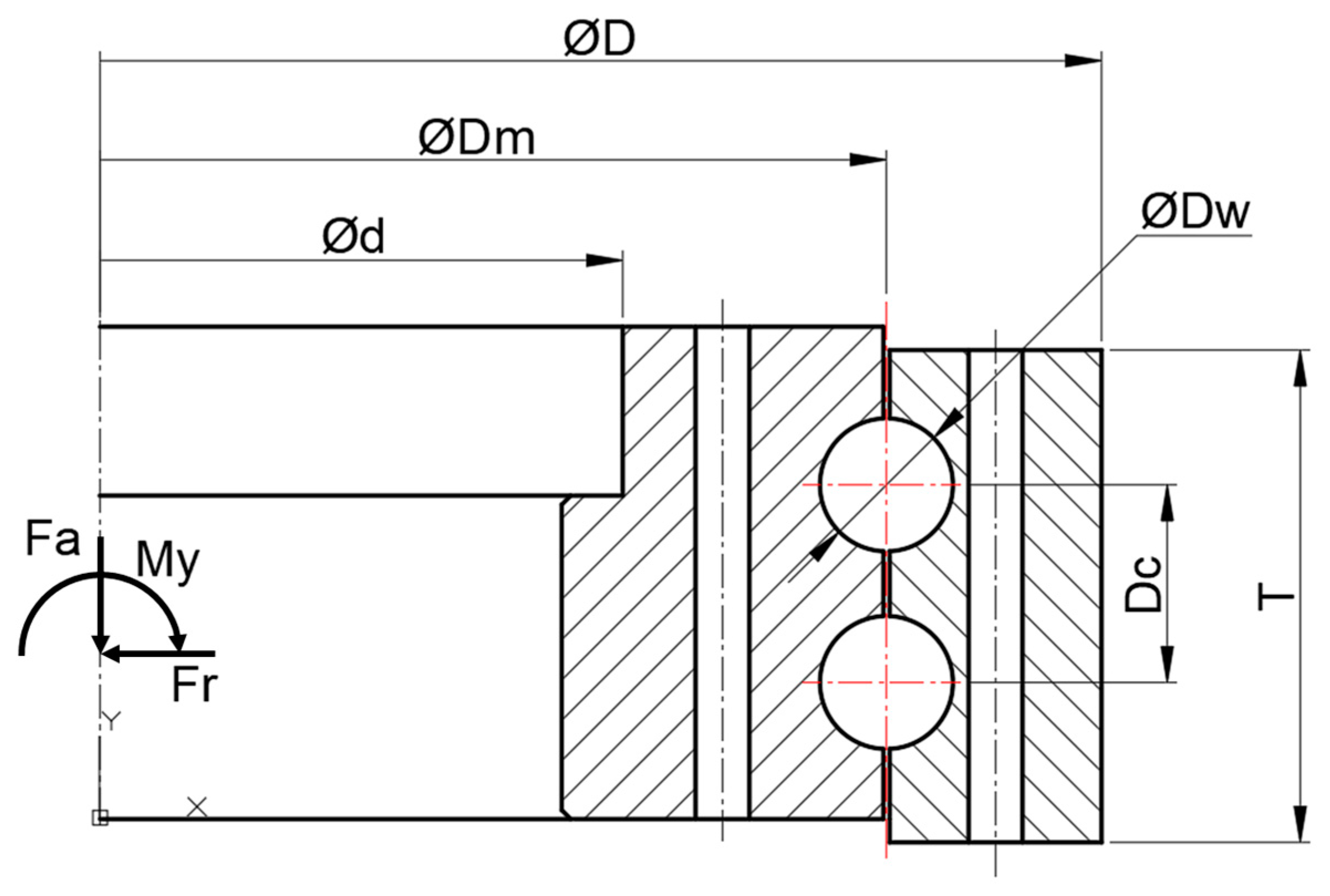
2.1. Bearing Information

The subject of the present study was a pitch ball bearing for 8 MW wind turbines; the bearing had dimensions of Ø5200 mm for the outer ring and Ø4957 mm for the inner ring and a height of 274 mm. In each row, 160 balls with a diameter of Ø71.32 mm were assembled, and the total number of assembled balls was 320. Table 1 shows the dimensions of the pitch bearings, and Figure 1 shows the simplified shape of the bearings. The material of the bearing raceway was 42CrMo4 + QT.

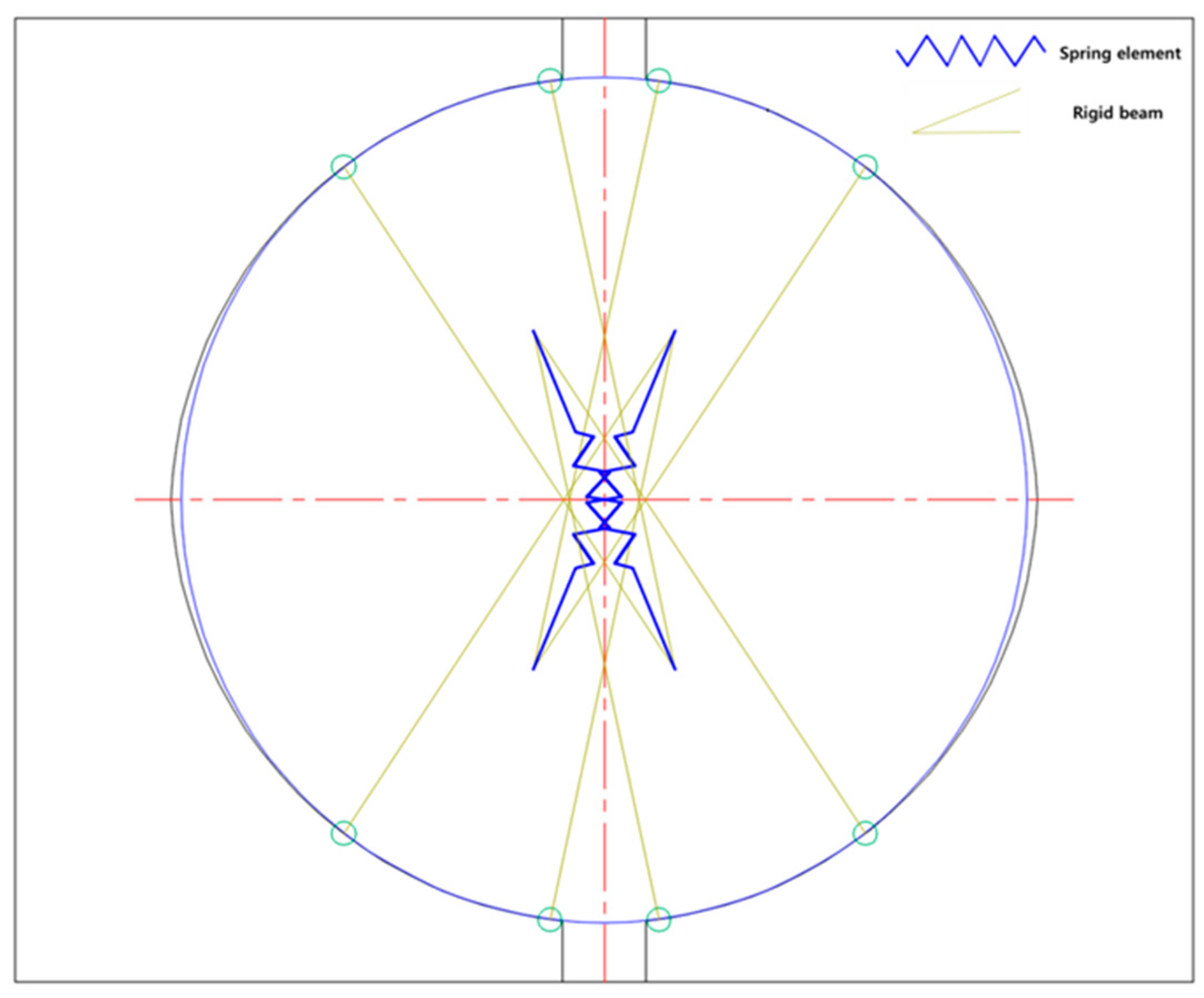
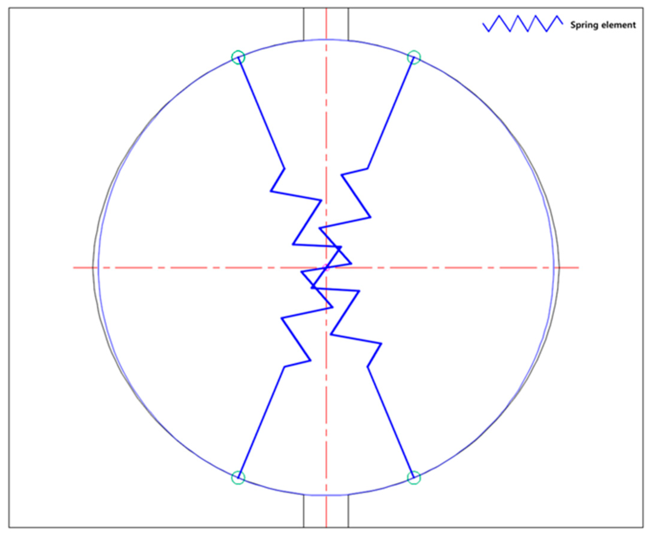
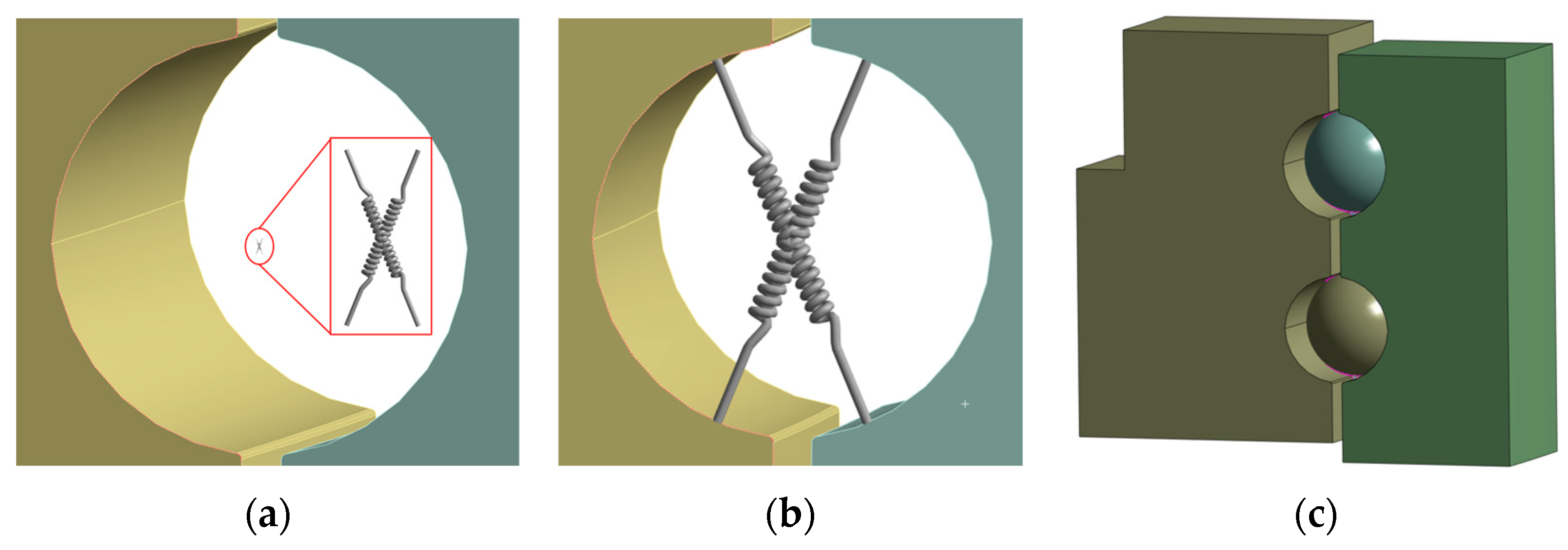
2.2. Four-Contact FE Bearing Model

In the present study, three models were used to analyze the deformation and the contact stress when load was applied to a 2-row 4-contact ball bearing. The Daidie spring model using a nonlinear spring, which is traditionally studied most, is a model in which the centers of the individual raceways in contact with the balls are connected with a nonlinear spring element, and two rigid elements are connected at the centers of the individual raceways. Figure 2 shows the Daidie spring model.
In Gao’s method [10], a single nonlinear spring element is connected to the point at which the ball and the raceway meet according to the contact angle. However, when large displacement of the outer ring occurs, change in the contact angle increases, and thus the load cannot be supported by a single spring element. Figure 3 shows Gao’s spring model.
Replacement of balls with nonlinear spring elements requires good stiffness of the balls, which can be calculated using the formula presented by Houpert [3] and Daidie [8]. In the formula below, Q is the load, D w is the ball diameter, D profile is the raceway diameter, and s is the dimension ratio of the ball diameter to the raceway diameter. Equation (1) expresses the dimension ratio. δ in Equation (2) represents the stiffness, and the formula indicates that the displacement and the load Q have a nonlinear relationship.
Dimension ratio of the ball to the raceway:
s = D w D profile
Formula for calculating the stiffness of a ball:
δ = 8.97 × 10 4 ( 1 s ) 0.1946 Q 2 / 3 D w 1 / 3
In the models in which balls are replaced by spring elements, the accurate behavior and deformation of the contact points between the rolling element and the raceway are difficult to predict; it is also difficult to represent the movement of the contact points as the actual movement. Therefore, a method for analyzing the displacement after performing FE mesh ball modeling and analysis was proposed. Global analysis was performed to obtain the displacement when an external force was applied to all the bearings under three conditions, and contact stress analysis was performed through a sub-model with cut boundary constraints in order to calculate the accurate contract stress. The ANSYS R2 2023 Mechanical software program was employed for the FEA.

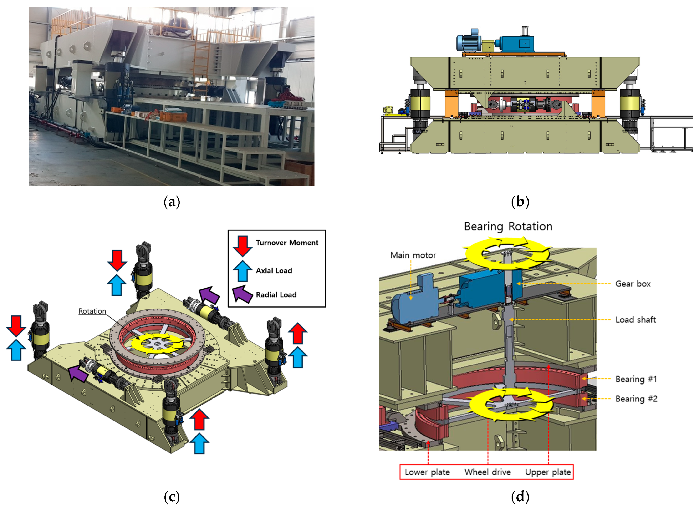
2.3. Test Bench of Pitch Bearing

In the present study, a bearing test was performed using a test bench to evaluate the precision of the FEAs, and the bearing test results were compared with the results of the FEAs to evaluate the analytical precision. The equipment can be used to simultaneously test two bearings; it has a base frame as a bottom platform, a loading frame as the top platform, and six hydraulic devices between the base frame and the loading frame. The bearing test bench is shown in Figure 4a,b. The six hydraulic devices are installed to apply radial load, axial load, and turnover moment, as shown in Figure 4c, and a durability test under the fatigue load case can be performed using the electric motor and drive shaft installed in the center of the test bench, as shown in Figure 4d. The specifications of the bearing test bench are summarized in Table 2.
In the present study, only turnover moment, which has the highest impact on the bearings, was applied. The bearing test with the test bench was performed to apply only the turnover moment by operating the hydraulic device on the left in the negative direction and the hydraulic device on the right in the positive direction.

3. Finite Element Analysis of Pitch Bearing

In the present study, FEAs were performed separately from the global model and the sub-model. When the mesh is finely generated in global model analysis, due to the contact points and nodes, there may be problems in the convergence, analytical time, and CPU capacity. Therefore, in the present study, a coarse mesh was generated in the global model analysis to calculate the displacement, and then, a fine mesh was generated in the sub-model analysis with cut boundary constraints to calculate the contact stress. The global analysis and sub-model technique were based on the research of Sanit Vanant [20], stating that there is no stress difference between concentrated and distributed loads when the location of the load is far away, and the research of Liu [21], stating that the lattice density has a large effect on stress but no effect on displacement in static analysis, C hang [22] is based on (2-D) beam element model, the theory of sub-model was theoretically deduced, based on sub-modeling technique of nodal displacements, the results of the global model and the sub-model for the skew bridge were compared and studied in terms of stress field and plastic damage of concrete. Therefore, if the displacement obtained from the global analysis is input as the boundary condition of the sub-modeling analysis, reasonable analysis accuracy can be expected. For the convergence of nonlinear conditions, the analysis was divided into 100 substeps. Force and displacement convergence tolerance was applied to the analysis with the “Program controlled” option. The force convergence criterion of “Program controlled” option has a maximum value of 5 × 10⁻⁶, which is calculated as the product of convergence tolerance of 0.05% and the internally calculated minimum reference value for force or a maximum of 0.01.

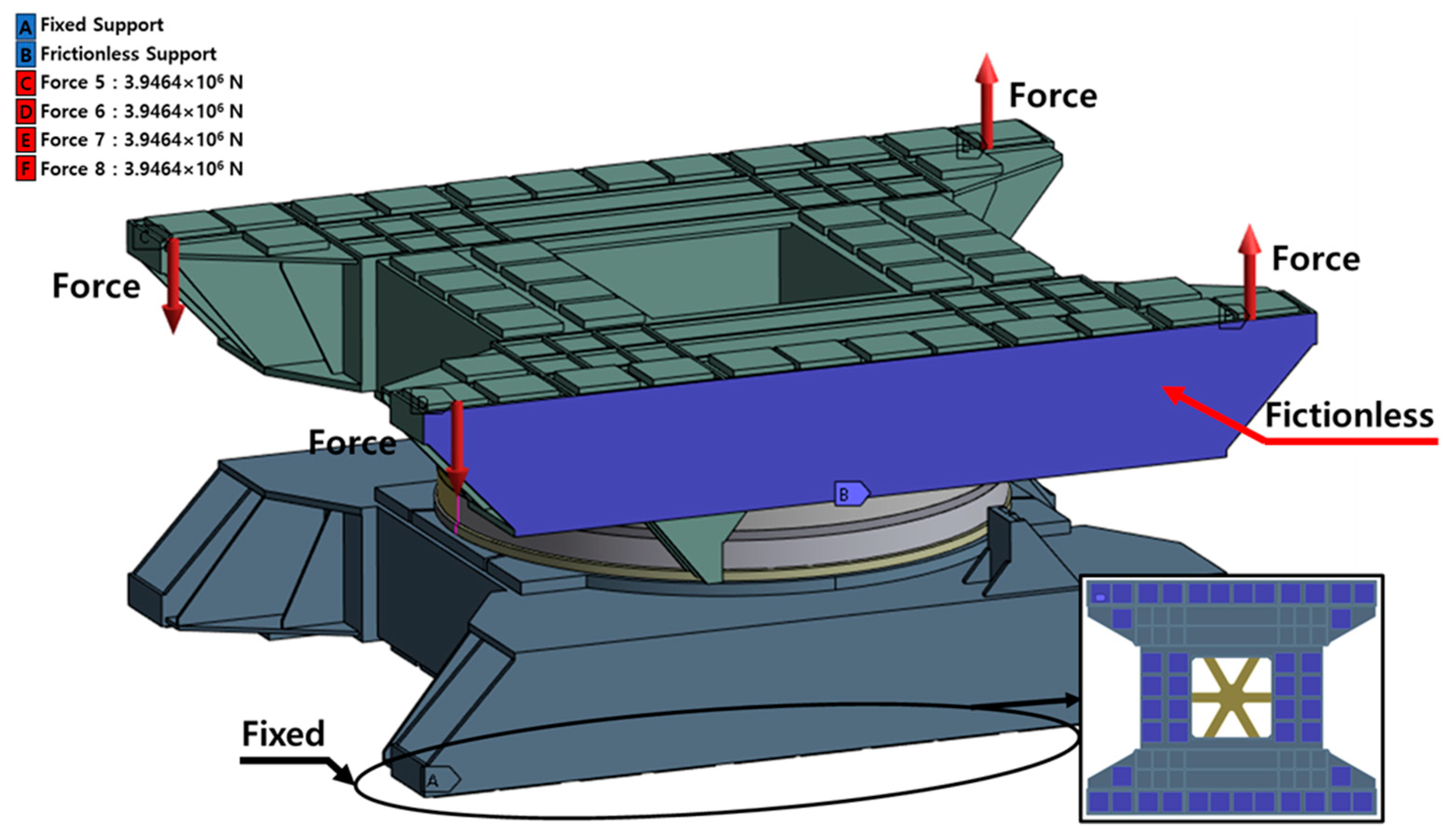
3.1. Global Model Finite Analysis Condition

In the global analysis, a maximum turnover moment was applied to analyze the deformation of the bearing and test bench. The hydraulic cylindrical force was 3946.4 kN because the distance between the cylinders was 4.0 m and the maximum turnover moment was 63,142 kNm. The global model for FEA is shown in Figure 5, composed of two bearings, the test bench, and the several jigs presented in Figure 4d. The turnover moment was modeled according to four vertical hydraulic forces. The bottom surface was fixed, and the side plate was frictionlessly supported to constrain movement. The FEA boundary conditions of the ball contacting sector between the raceway and ball were set as shown in Figure 6a,b for the spring models and as shown in Figure 6c for the FE mesh ball model. The bearing in the global analysis was modeled by rotating and arraying the ball treatment sector model described in Figure 6.
The regions where the components came into contact with each other, such as the frames, bearings, and jigs, were set in the ‘bonded’ condition, and the regions where the ball and raceway came into contact with each other were set in the ‘frictional’ condition.

3.2. Sub-Model Finite Analysis Condition

An accurate stress analysis requires fine elements. However, a global model, which is large and has many contact points between the balls and the raceway, may have problems in the analytical convergence and analytical time when the elements are fine. Therefore, sub-model analysis was performed with the cut boundary constraints. In the sub-model analysis, a model with a coarse mesh was first analyzed, and then a model for a specific part was prepared and this part was analyzed with a finer mesh. To confirm the accurate contract stress of the bearings, global model displacement analysis was performed to cut the point where the maximum displacement was found, and a model of the point was built. Then, the displacement results obtained from the global model analysis were mapped to perform the sub-model analysis. Figure 7 illustrates the boundary conditions used in the sub-model analysis.

4. Results

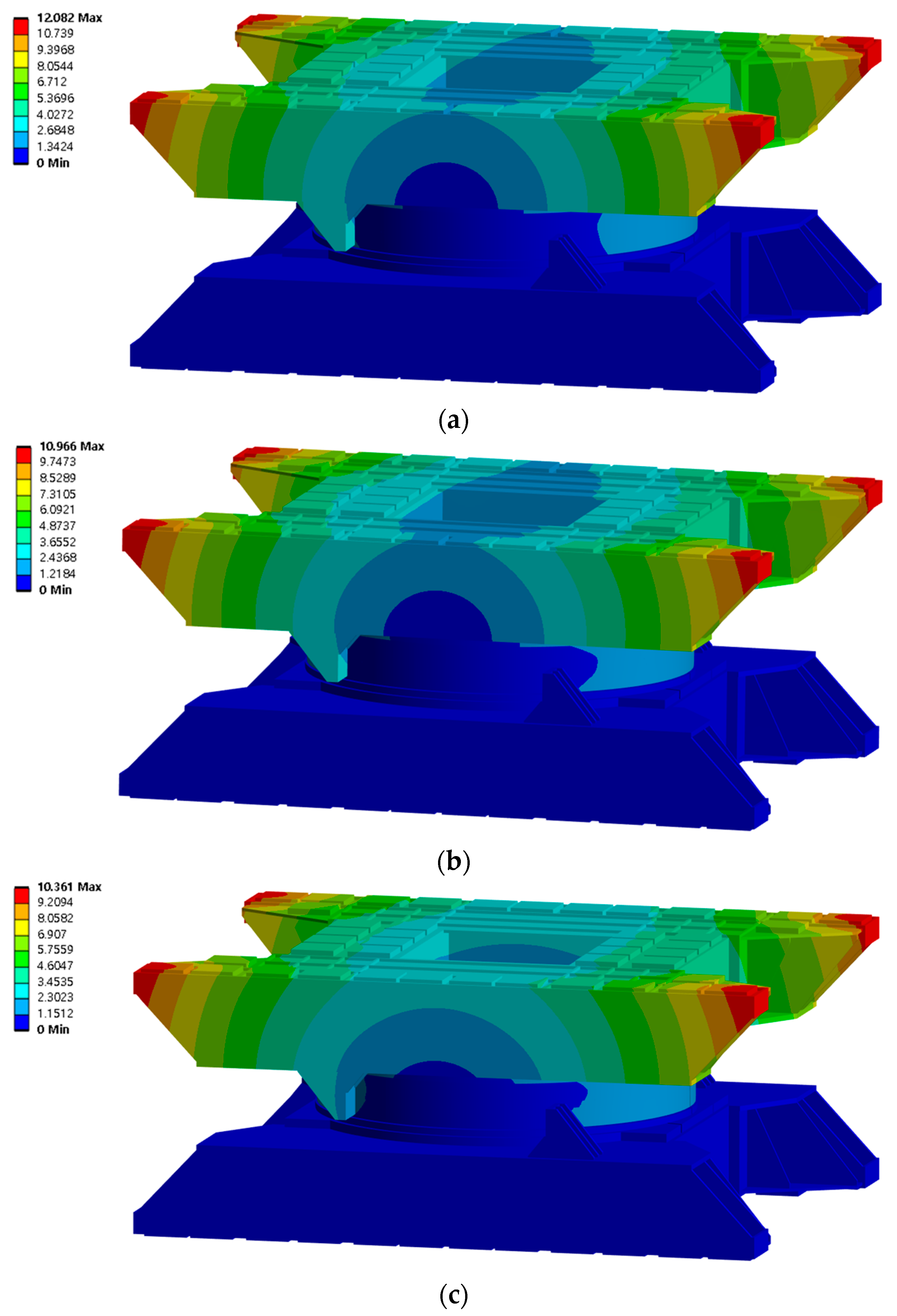
4.1. Global Model Analysis Results

In the FEAs, global model analysis of the balls was performed with the Daidie spring model, the single-spring model, and the FE mesh ball model; the results of the global analysis are shown in Figure 8. The maximum displacement of the bearing test bench was found on the side at which the hydraulic device was connected. The maximum displacement was approximately 12.08 mm in the single-spring model, 10.97 mm in the Daidie spring model, and 10.36 mm in the FE mesh ball model.
Figure 9 shows the displacement of the bearings in each of the FEA models. The displacement of the bearings was 3.199 mm in the single-spring model, 2.682 mm in the Daidie spring model, and 2.379 mm in the FE mesh ball model. Compared to the model that exhibited results that were most similar to the test results, the difference for the single-spring model was 0.82 mm and that for the Daidie spring model was 0.3 mm. The displacement difference was particularly large in the single-spring model, which is probably because an excessive displacement was generated at the inner ring and the outer ring and the change in the contact angle increased, thereby making it difficult for a one-dimensional spring element to support the load.

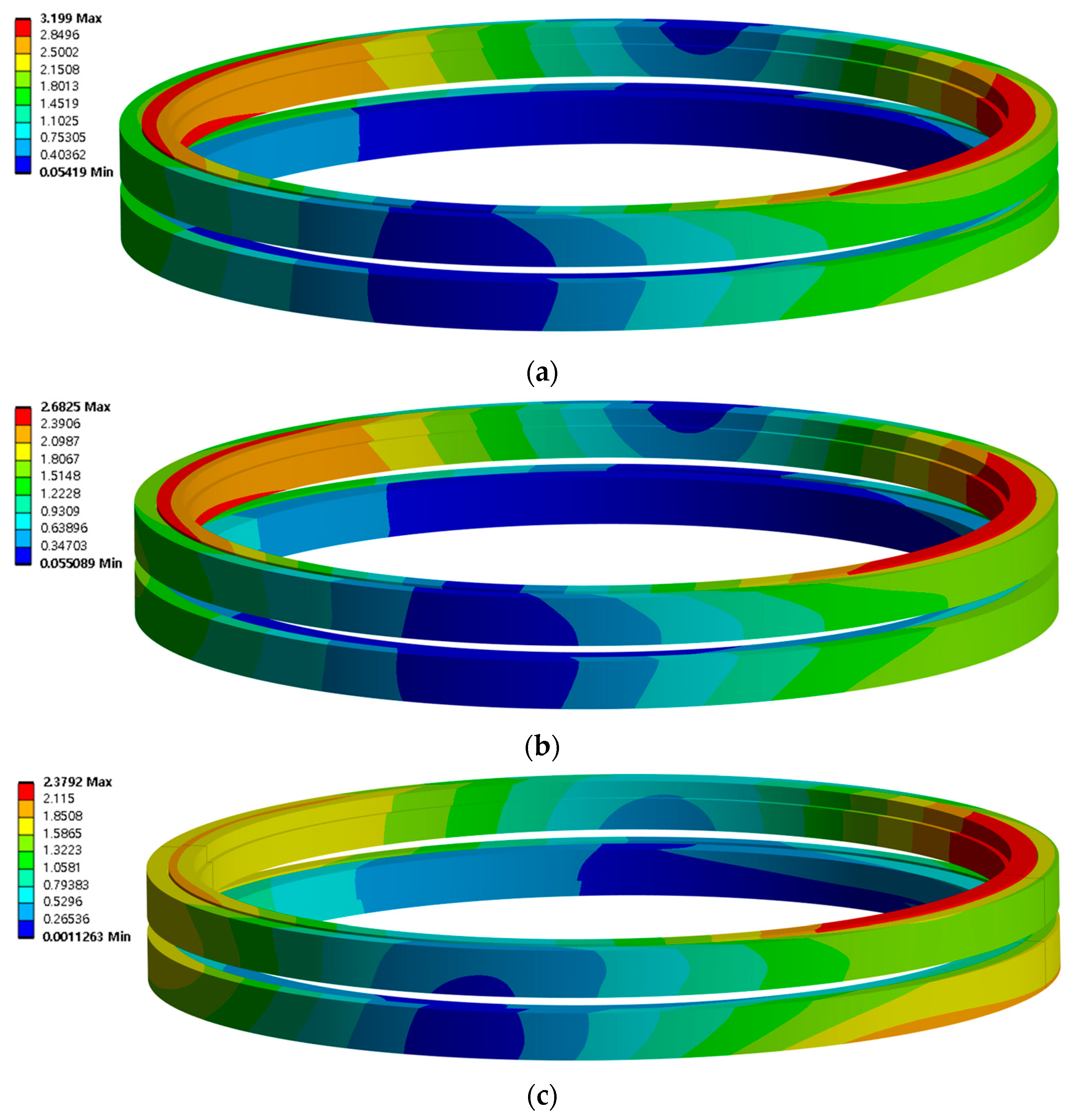
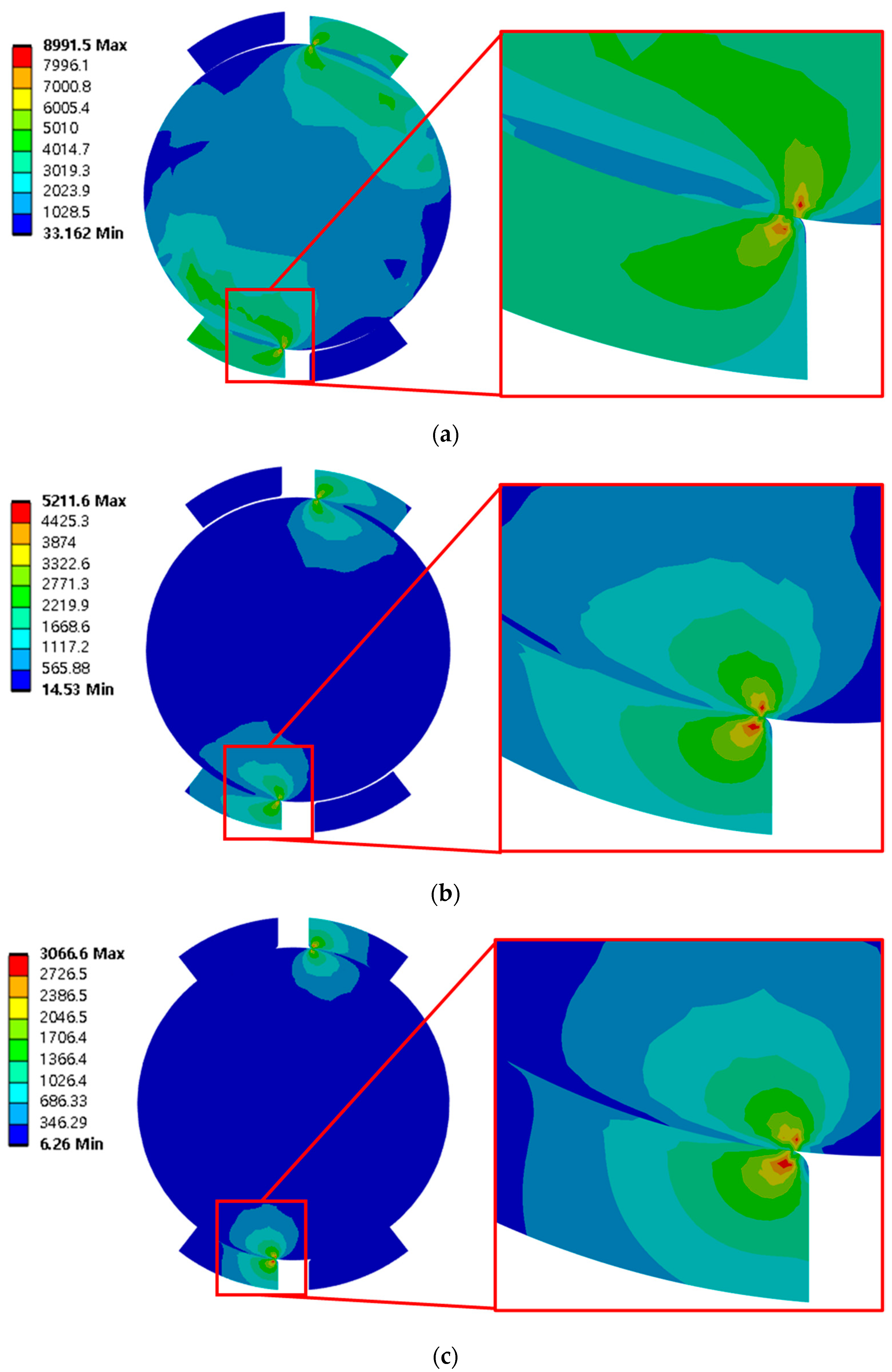
4.2. Sub-Model Analysis Result

A sub-model analysis was performed to accurately analyze the contact stress of the bearings. Figure 8 shows the contact stress under different conditions. The distribution contour of the contact stress was similar among the three models. The maximum contact stress is 8991 MPa in Figure 10a, 4675 MPa in Figure 10b, and 3067 MPa in Figure 10c. The single-spring model exhibited the highest stress, which was about 1000 MPA higher than that of the Daidie spring model and the FE mesh ball model.

4.3. Comparison of Results between FEAs and the Test with the Test Bench

Global model analysis was carried out to calculate the displacement, and the sub-model was performed to calculate the accurate contact stress. The bearing test results obtained by using the test bench were compared with the results of the FEAs to evaluate the precision of the FEAs. The displacement was 10 mm in the bearing test results obtained by using the test bench, and this value was used for the comparison with the FEAs. According to the results of the global model analysis in the FEAs, the displacement was 12.08 mm in the single-spring model, 10.97 mm in the Daidie spring model, and 10.36 mm in the FE mesh ball model. The difference between the test results and the FEA results was 2 mm (17%) for the single-spring model, 0.97 mm (9%) for the Daidie spring model, and 0.36 mm (3%) for the FE mesh ball model. Therefore, the results obtained from the FE mesh ball model were most similar to the bearing test results. Figure 11 compares the results of the FEAs with the bearing test results.
To evaluate the safety of the bearings, as shown in Table 3, the safety factor was calculated for the FEA models using the contact stress of the model that exhibited results most similar to the bearing test results based on the allowable stress 4200 MPa, presented in the NREL DG:03 Bearing Guideline.

4.4. Discussion of the Analysis Results

In this study, simplified spring models of ball bearings were analyzed by means of finite element analysis. One of these models is the single-spring model [10], which can replace the ball with two springs by connecting the two raceway contact points with one spring, and the other is the Daidie model [8], which proposes a spring between the contact points of two rigid beams. Finite element analyses were performed for these spring models and the FE mesh ball model, in which the ball is meshed as a solid model. To evaluate the accuracy of the FEA results for both spring models, the displacement of FEA using the spring models and the ball model was compared with that of the test bench. As summarized in the previous section, the test bench deformation shows an error of 17% for the single-spring model, 9% for the Daidie model, and 3% for the FE mesh ball model. This error is because the spring element is a structure that connects the contact angle of the raceway and the ball, so when a large overturning moment is imposed, the contact angle changes. Because the spring element transmits load only in the longitudinal direction, it is believed that if the contact angle changes, the load it supports may change and the accuracy of the analysis may decrease. The Daidie model also has the same characteristics, but because it connects the contact points of the rigid beam at two points on the raceway, it is judged that there is little difference in the displacement value for the change in contact angle. The phenomenon of high deformation for the same load in the analysis using the Daidie model has the same tendency as in the study by Graßmann, M. [18].
In this study, when conducting tests on a test bench, only the vertical displacement of a hydraulic cylinder indicated by the maximum turnover moment was measured, so positional deformation was not compared with FEAs.

5. Conclusions

The analytical accuracy of the finite element model when calculating the stresses acting on a ball and raceway and the displacement of the bearing when a load is applied to a slewing bearing was compared with the results of a bearing tester, and the following conclusions were obtained.
(1)
According to the results of the global model analysis, the differences in displacement from the test results were 2.0 mm (17%) in the single-spring model, 0.97 mm (9%) in the Daidie spring model, and 0.36 mm (3%) in the FE mesh ball model. Therefore, the results from the FE mesh ball model were the most similar to the test results.
(2)
According to the results of the sub-model analysis, carried out based on the results of the global model analysis, the contact stress was 8991 MPa in the single-spring model, 4675 MPa in the Daidie spring model, and 3067 MPa in the ball model. The ball model shows the lowest contact stress. The single-spring model and the Daidie spring model showed high stress values, probably because they failed to simulate contact angle changes caused by turnover moments.
(3)
To evaluate the safety of bearings, a safety factor was calculated using the contact stress of the model that exhibited results most similar to the bearing test results based on the static allowable stress of ball bearings at 4200 MPa, presented in the NREL DG:03 Bearing Guideline. The calculated safety factor was 2.271 for the inner ring and 2.721 for the outer ring.
(4)
Further studies may need to be conducted to measure the displacement of both the bearing test bench and the bearings, considering the composite loads together, including the axial load, radial load, and turnover moment. The FEA results can be compared among the spring models and the FE mesh ball models with or without a preload for validation.

Author Contributions

Writing—original draft, S.-W.K.; software, J.-W.S.; visualization, J.-P.H.; data curating, H.-J.K.; supervision, J.-H.K. All authors have read and agreed to the published version of the manuscript.

Funding

This work was supported by the Korea Institute of Energy Technology Evaluation and Planning (KETEP) and the Ministry of Trade, Industry and Energy (MOTIE) of the Republic of Korea (No. 20203010020040 and No. RS-2023-00302111).

Institutional Review Board Statement

Not applicable.

Informed Consent Statement

Not applicable.

Data Availability Statement

Data are contained within the article.

Conflicts of Interest

The authors declare no conflicts of interest.

References

  1. Abhijith, S. Study of Pitch Bearings in Wind Turbines—A Model Based Approach. Master’s Thesis, KTH Industrial Engineering and Management Machine Design, Stockhol, Sweden, 2018. [Google Scholar]
  2. Harris, T.A. Rolling Bearing Analysis, 3rd ed.; Wiley-Interscience: New York, NY, USA, 1991. [Google Scholar]
  3. Houpert, L. An Engineering Approach to Hertzian Contact Elasticity—Part I. J. Tribol. 2000, 123, 582–588. [Google Scholar] [CrossRef]
  4. Antoine, J.-F.; Abba, G.; Molinari, A. A New Proposal for Explicit Angle Calculation in Angular Contact Ball Bearing. J. Mech. Des. 2005, 128, 468–478. [Google Scholar] [CrossRef]
  5. Aguirrebeitia, J.; Avilés, R.; de Bustos, I.F.; Abasolo, M. Calculation of General Static Load-Carrying Capacity for the Design of Four-Contact-Point Slewing Bearings. J. Mech. Des. 2010, 132, 064501. [Google Scholar] [CrossRef]
  6. Aguirrebeitia, J.; Plaza, J.; Abasolo, M.; Vallejo, J. General static load-carrying capacity of four-contact-point slewing bearings for wind turbine generator actuation systems. Wind. Energy 2012, 16, 759–774. [Google Scholar] [CrossRef]
  7. Zupan, S.; Prebil, I. Carrying angle and carrying capacity of a large single row ball bearing as a function of geometry parameters of the rolling contact and the supporting structure stiffness. Mech. Mach. Theory 2001, 36, 1087–1103. [Google Scholar] [CrossRef]
  8. Daidié, A.; Chaib, Z.; Ghosn, A. 3D Simplified Finite Elements Analysis of Load and Contact Angle in a Slewing Ball Bearing. J. Mech. Des. 2008, 130, 082601. [Google Scholar] [CrossRef]
  9. Duijvendijk, M.; Van, M.; Kalverboer, A.; De Gruiter, T. Benchmark of Bolted Bearing Connection Models in Wind Turbines. In Proceedings of the European Wind Energy Conference and Exhibition, Athens, Greece, 27 February–2 March 2006; pp. 1–7. [Google Scholar]
  10. Gao, X.H.; Huang, X.D.; Wang, H.; Chen, J. Modelling of ball raceway contacts in a slewing bearing with nonlinear springs. Proc Inst. Mech. Eng. Part C 2011, 225, 827–831. [Google Scholar] [CrossRef]
  11. Starvin, M.S.; Babu, S.; Aithal, S.; Manisekar, K.; Chellapandi, P. Finite element simulation of nonlinear deformation behaviour in large diameter angular contact thrust bearing. Sci. Res. Essays 2013, 8, 128–138. [Google Scholar] [CrossRef]
  12. Aguirrebeitia, J.; Plaza, J.; Abasolo, M.; Vallejo, J. Effect of the preload in the general static load-carrying capacity of four-contact-point slewing bearings for wind turbine generators: Theoretical model and finite element calculations. Wind Energy 2013, 17, 1605–1621. [Google Scholar] [CrossRef]
  13. Plaza, J.; Abasolo, M.; Coria, I.; Aguirrebeitia, J.; Ferna’ndez de Bustos, I. A new finite element approach for the analysis of slewing bearings in wind turbine generators using superelement techniques. Meccanica 2015, 50, 1623–1633. [Google Scholar] [CrossRef]
  14. Schwack, F.; Flory, H.; Poll, G.; Stammler, M. Free contact angles in pitch bearings and their impact on contact and stress conditions. In Proceedings of the Wind Europe, SUMMIT 2016, Hamburg, Germany, 27–30 September 2016; pp. 27–29. [Google Scholar]
  15. Zhang, H.; Chen, S.; Dou, Y.; Fan, H.; Wang, Y. Mechanical model and contact properties of double row slewing ball bearing for wind turbine. Rev. Adv. Mater. Sci. 2021, 60, 112–126. [Google Scholar] [CrossRef]
  16. Porziani, S.; Biancolini, M.E.; Brutti, C. Analysis of Wind Turbine Pitch 4-Point Contact Bearing. IOP Conf. Ser. Mater. Sci. Eng. 2023, 1275, 012034. [Google Scholar] [CrossRef]
  17. He, P.; Hong, R.; Wang, H.; Ji, X.; Lu, C. Calculation analysis of yaw bearings with a hardened raceway. Int. J. Mech. Sci. 2018, 144, 540–552. [Google Scholar] [CrossRef]
  18. Graßmann, M.; Schleich, F.; Stammler, M. Validation of a finite-element model of a wind turbine blade bearing. Finite Elements Anal. Des. 2023, 221, 103957. [Google Scholar] [CrossRef]
  19. He, P.; Qian, Q.; Wang, Y.; Liu, H.; Guo, E.; Wang, H. Influence of finite element mesh size on the carrying capacity analysis of single-row ball slewing bearing. Adv. Mech. Eng. 2021, 13, 16878140211009030. [Google Scholar] [CrossRef]
  20. Saint-Vanant, D. Mémoire sur la flexion des prismes. J. Math. Pures Appl. 1856, 1, 89–189. [Google Scholar]
  21. Liu, Y.; Glass, G. Effects of Mesh Density on Finite Element Analysis. In Proceedings of the SAE 2013 World Congress & Exhibition, Detroit, MI, USA, 16–19 April 2013. [Google Scholar]
  22. Chang, S.; Liu, K.; Yang, M.; Yuan, L. Theory and implementation of sub-model method in finite element analysis. Heliyon 2022, 8, e11427. [Google Scholar] [CrossRef] [PubMed]
Figure 1. Structure of the two-row four-contact pitch bearing.
Energies 17 00692 g001
Figure 2. Daidie spring element connection of balls.
Energies 17 00692 g002
Figure 3. Single spring element connection of balls.
Energies 17 00692 g003
Figure 4. Bearing test bench. (a) Test bench; (b) test bench modeling; (c) test bench loading mechanism; (d) inner ting rotating method for the durability test.
Energies 17 00692 g004
Figure 5. Global model with force and boundary conditions.
Energies 17 00692 g005
Figure 6. Ball treatment method for bearing FE analysis. (a) Daidie model. (b) Single-spring model. (c) FE mesh ball model.
Energies 17 00692 g006
Figure 7. Sub-modeling boundary conditions.
Energies 17 00692 g007
Figure 8. Global model strain analysis results using a spring element and ball: (a) single-spring model analysis; (b) Daidie spring model analysis; (c) ball model analysis.
Energies 17 00692 g008
Figure 9. Global bearing model strain analysis results using a spring element and ball: (a) single-spring model analysis; (b) Daidie spring model analysis; (c) ball model analysis.
Energies 17 00692 g009
Figure 10. Sub-model strain analysis results using a spring element and ball: (a) single-spring model analysis; (b) Daidie spring model analysis; (c) ball model analysis.
Energies 17 00692 g010
Figure 11. The comparison between the FEA analysis results and the test bench result.
Energies 17 00692 g011
Table 1. Parameters of the two-row four-contact pitch bearing.
ParameterSymbolValueUnit
Outer ring, outer diameter D5200mm
Ball center, ball center diameterDm4957mm
Inner ringd4660mm
Ball diameterDw71.32mm
Ball center intervalDc110mm
Outer ring height T274mm
Contact angleα67.29Deg
Maximum momentMy63,142kNm
Table 2. Bearing test bench specifications.
Bearing Test Bench
Maximum loadMoment76,000 kNm
Radial load2900 kN
Axial load9500 kN
Full assemblyWidth9385 mm
Length17,200 mm
Height4835 mm
Total weight270,000 kg
Table 3. FEA contact safety evaluation.
Max Contact Stress [MPa]Static Load Factor
Inner raceway3195.42.271
Outer raceway3008.42.721
Disclaimer/Publisher’s Note: The statements, opinions and data contained in all publications are solely those of the individual author(s) and contributor(s) and not of MDPI and/or the editor(s). MDPI and/or the editor(s) disclaim responsibility for any injury to people or property resulting from any ideas, methods, instructions or products referred to in the content.

