
Design and Optical Performance Evaluation of the Three-Dimensional Solar Concentrators with Multiple Compound Parabolic Profiles and Elliptical and Rectangular Receiver Shapes


Abstract
1. Introduction
- Develop a design method for the proposed concentrators with customizable receiver shapes.
- Assume elliptical receivers for the MultiPro-ECPCs and rectangular receivers for the MultiPro-RCPCs.
- Define the simulation conditions and evaluation indices.
- Evaluate the optical efficiency based on the axial angles and solar angles.
- Assess the irradiance distribution on the receiver and the axial angle coverage limits of the newly designed MultiPro-CPCs.
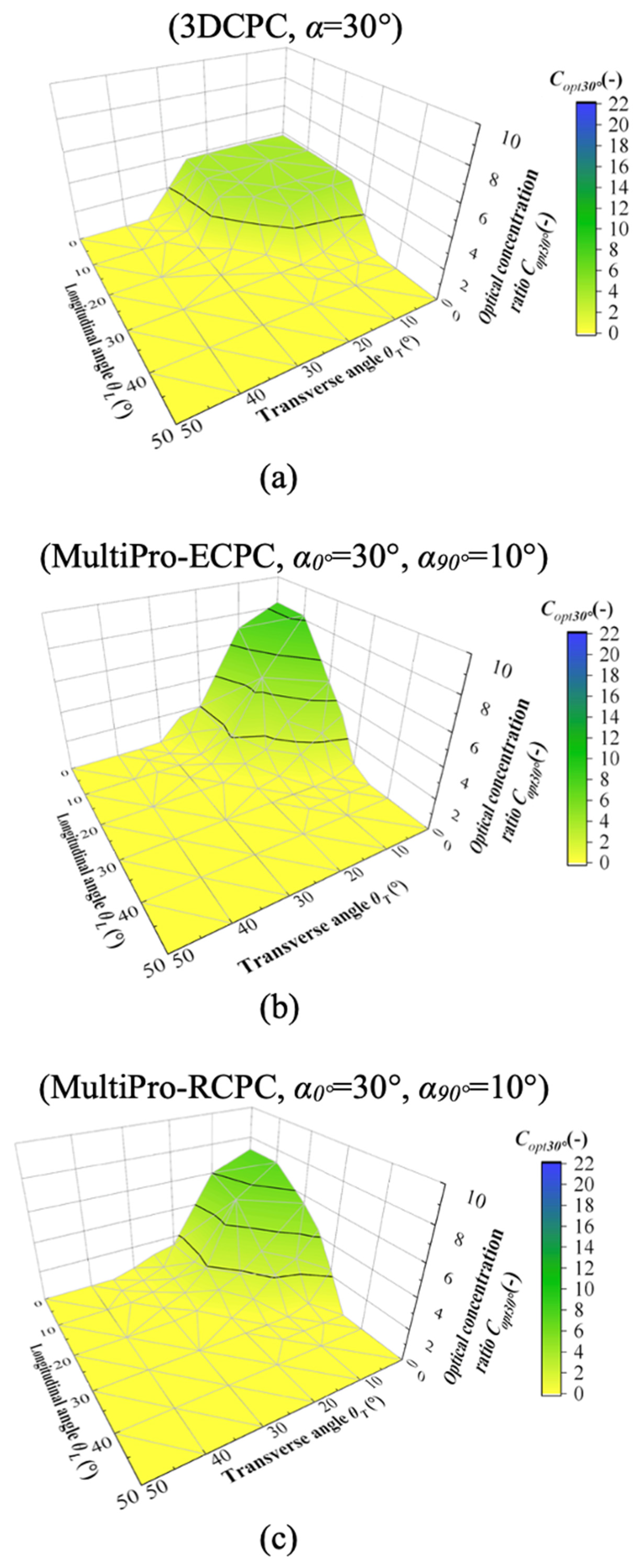
- Evaluate the optical concentration ratio based on the solar angles and a spatiotemporal interpretation.
2. Design of the Proposed Solar Concentrator
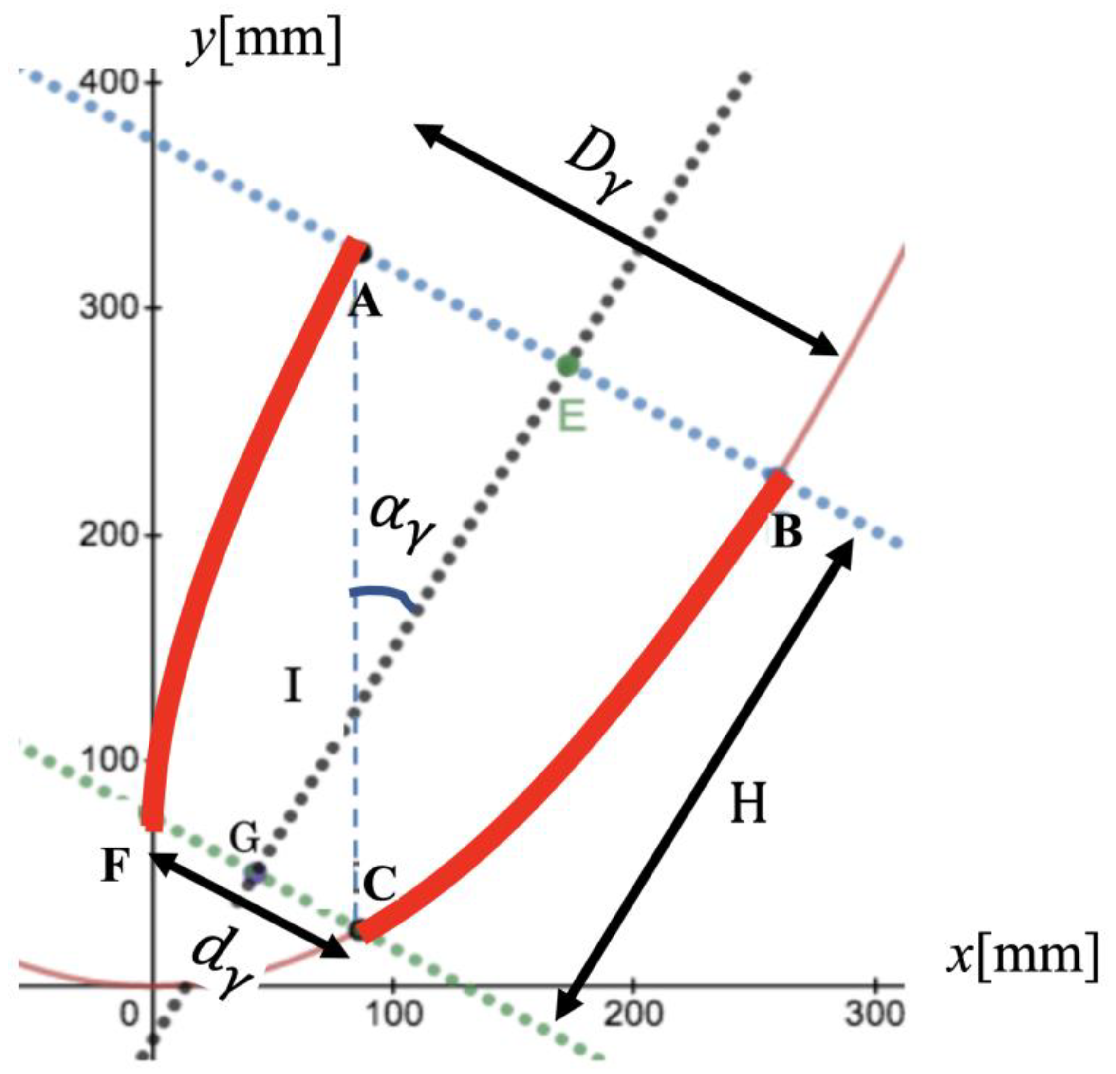
2.1. Design of the Profile
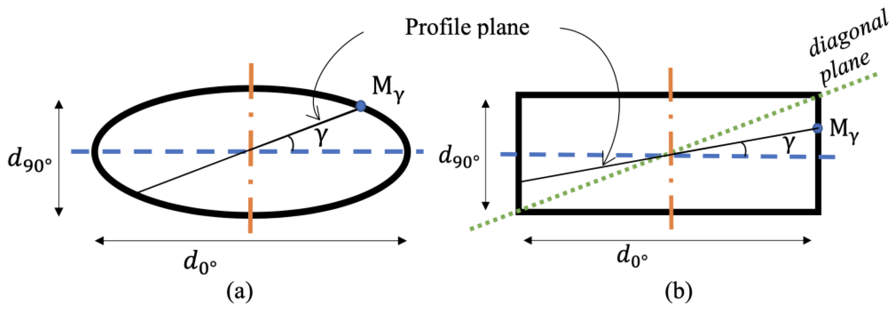
2.2. Design of the Receiver
2.3. Steps in the Geometry Generation of Novel CPCs and Conventional CPCs
- First, the receiver shape was chosen. In Figure 3, the receiver is rectangular. Then, the receiver length of the East–West direction d0°, the half-acceptance angle of the East–West direction α0°, and the half-acceptance angle of the North–South direction α90° were fixed.
- Secondly, the value of H and the East–West profile of the solar concentrator were determined from the fixed α0° and d0°, respectively.
- Thirdly, with H and α90°, the length of the receiver minor axis d90° was calculated and used to determine the North–South direction profile.
- Fourthly, the same method was repeated to design the CPC profile at each γ profile with and as the inputs and as the output. The receiver diameter is expressed in Equation (5) for the elliptical receiver and in Equation (7) for the rectangular receiver. Here, tγ, represented in Equation (6), is the angular parameter of the elliptical receiver at γ, and γdiag, represented in Equation (8), is the value of γ at the diagonal plane of the rectangular receiver. All equations are derived from the trigonometric relationships in an ellipse and a rectangle with the parameters shown in Figure 2.
- Finally, all the profiles were joined to form the concentrator, where γ varies from 0 to 90° every 15°.
2.4. Designed Solar Concentrators
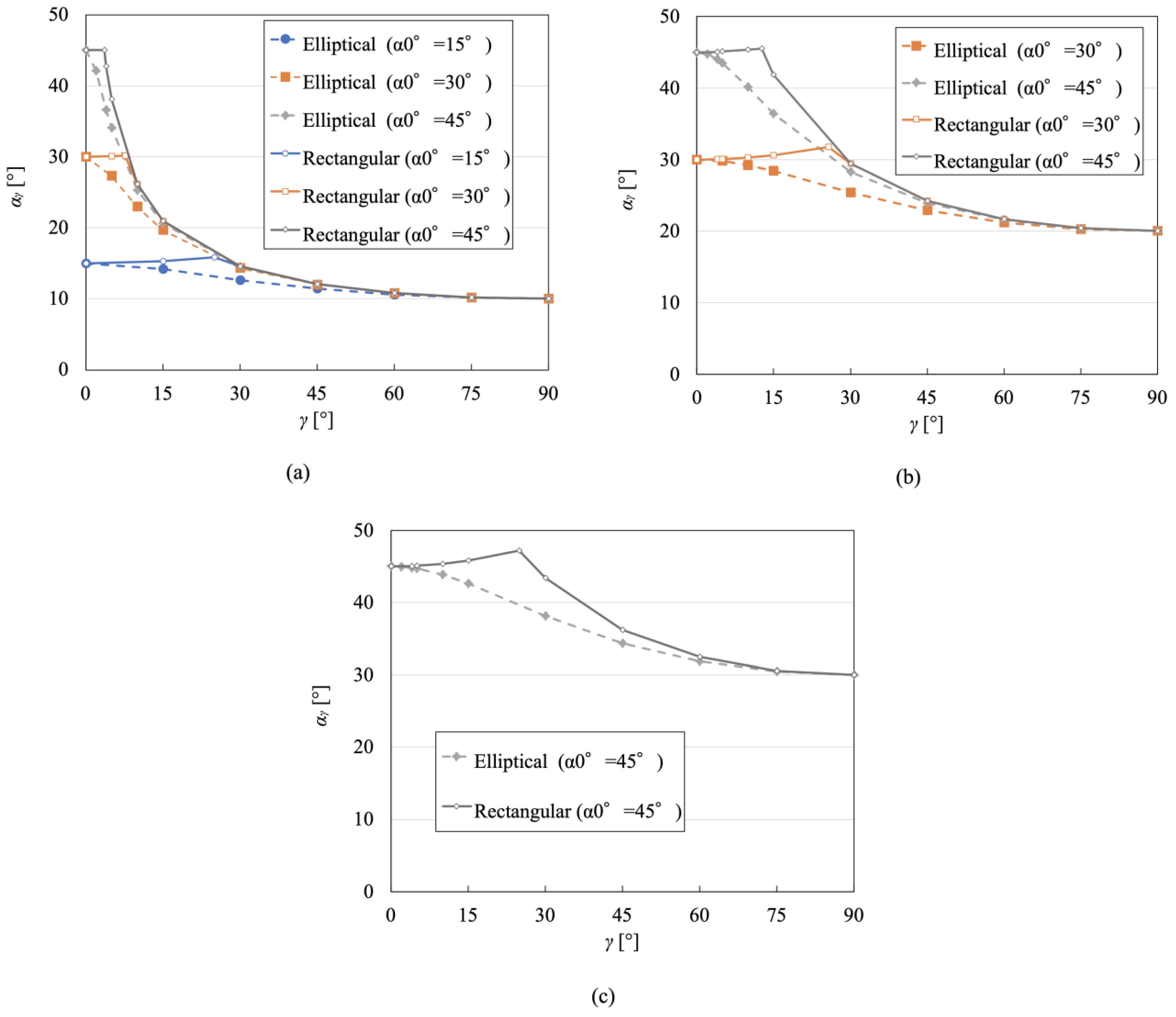
2.4.1. Variation of the Half-Acceptance Angle According to γ
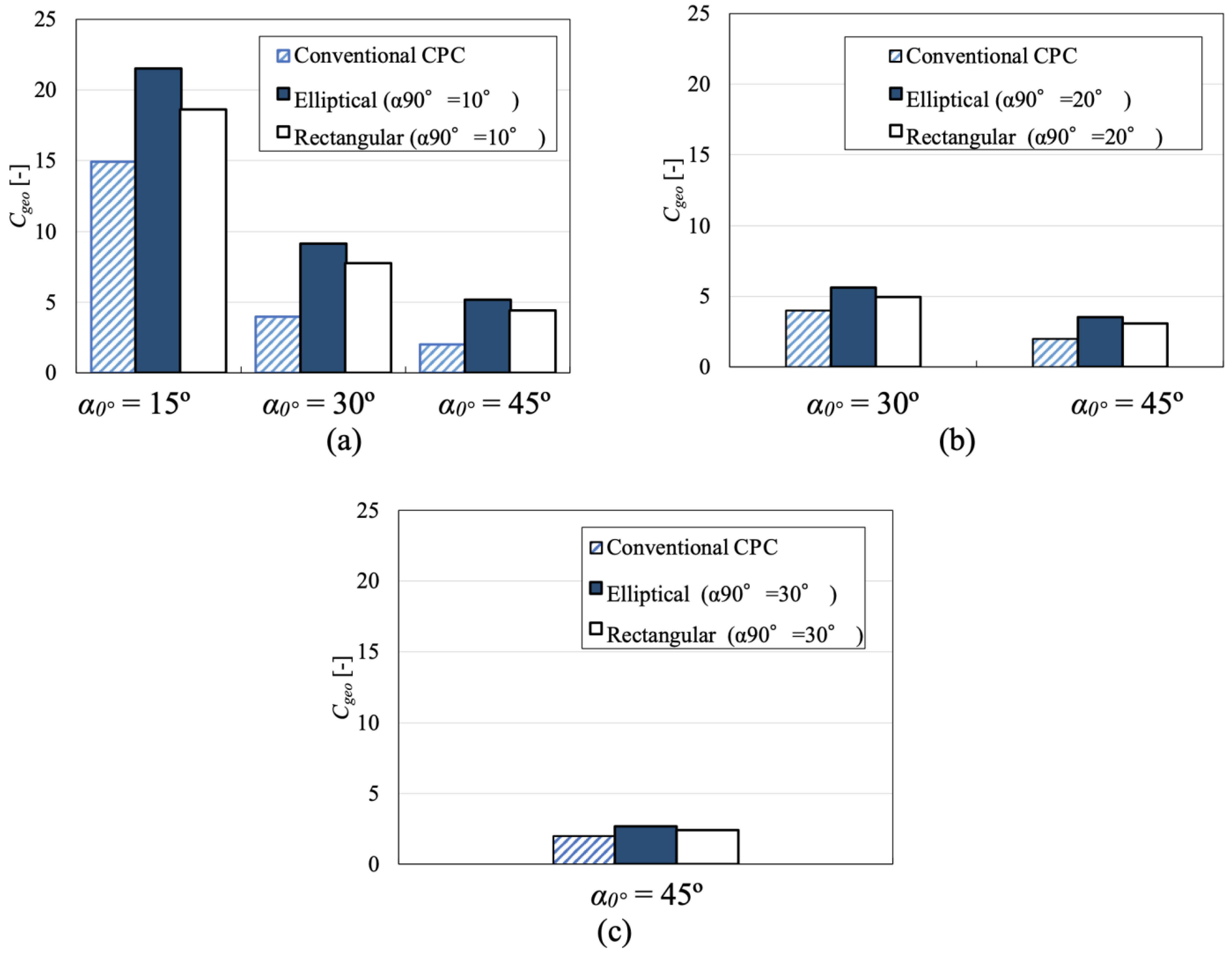
2.4.2. Geometric Concentration Ratio
3. Optical Simulation of the Designed Solar Concentrators
3.1. Simulation Conditions
3.2. Evaluation Indices
4. Results and Discussion
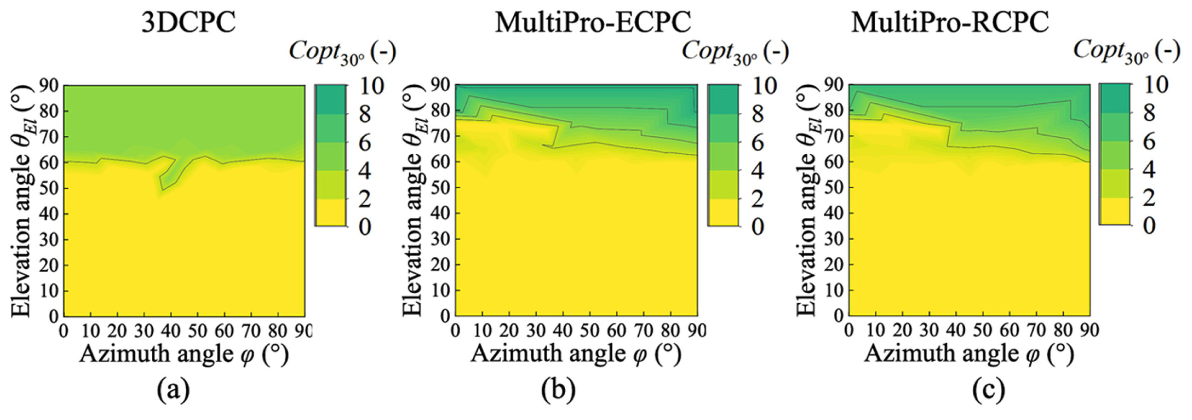
4.1. Optical Performance Based on the Axial Incidence Angle Coverage
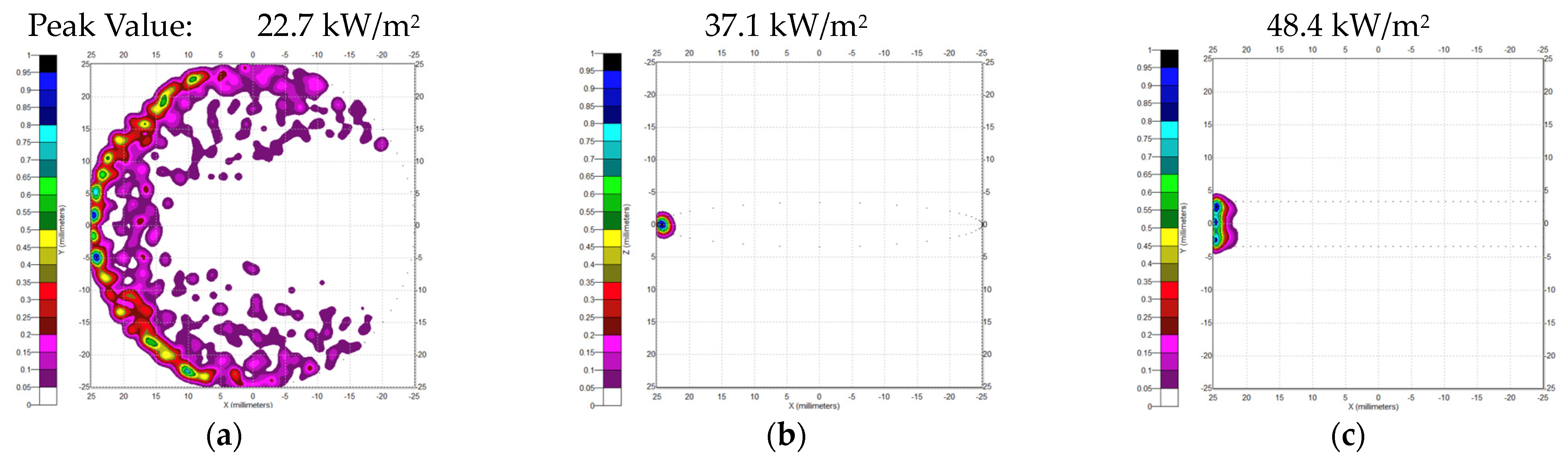
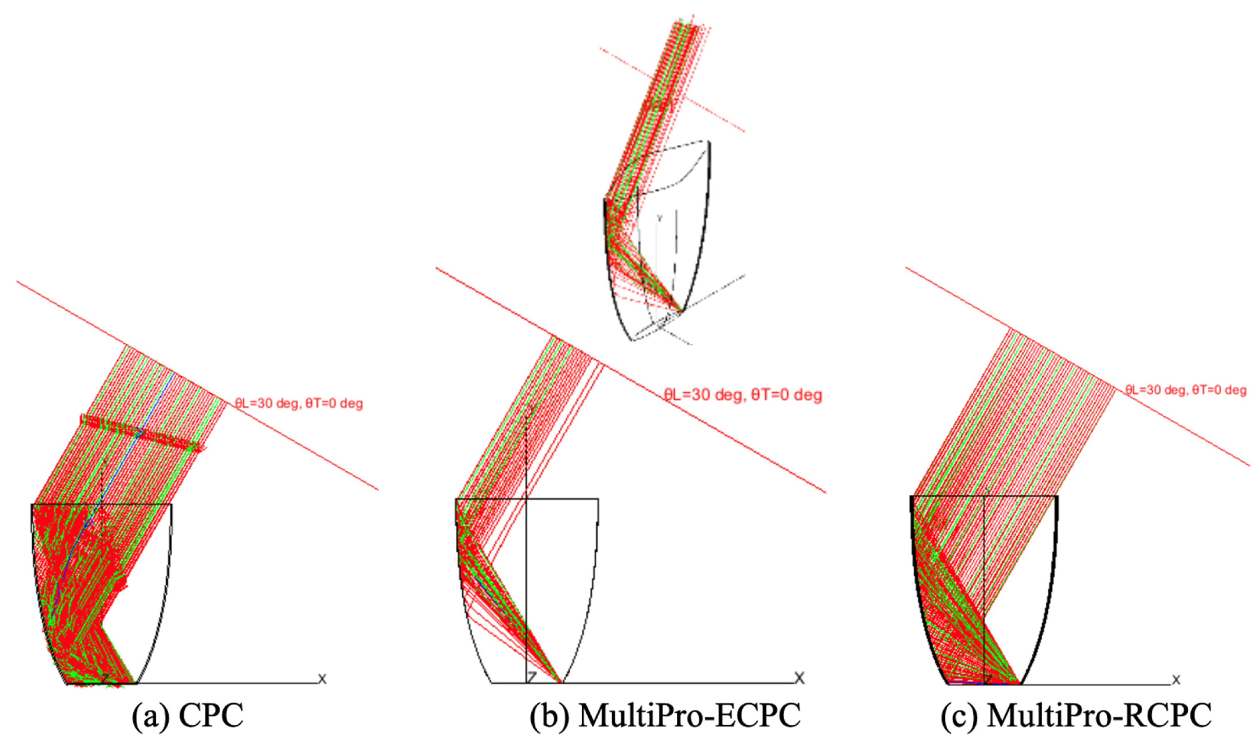
4.2. Irradiance Distribution on the Receiver and Absorbed Ray Path Inside the Concentrator
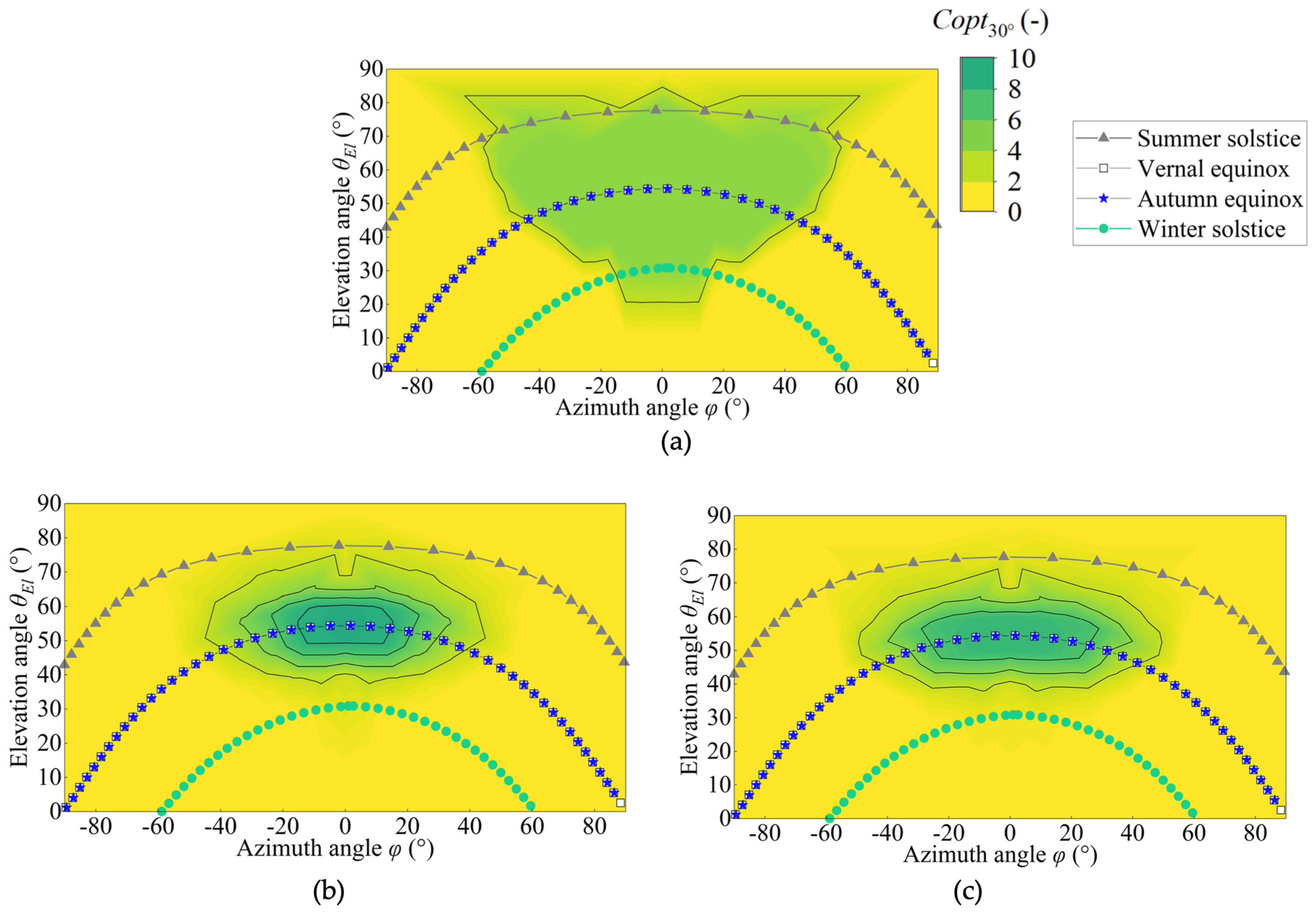
4.3. Optical Performance Based on the Solar Incidence Angle Coverage
5. Conclusions
Supplementary Materials
Author Contributions
Funding
Data Availability Statement
Acknowledgments
Conflicts of Interest
Nomenclature
| Abbreviations | |
| CPC | Compound parabolic concentrator |
| MultiPro-CPC | Concentrator with multiple CPC profiles |
| MultiPro-ECPC | Concentrator with multiple CPC profiles and an elliptical receiver |
| MultiPro-RCPC | Concentrator with multiple CPC profiles and a rectangular receiver |
| 2DCPC | Two-dimensional CPC |
| 3DCPC | Three-dimensional CPC |
| Notations | |
| AAbs (mm2) | Receiver area |
| AAp (mm2) | Aperture area |
| Cgeo (-) | Geometric concentration ratio |
| Copt (-) | Optical concentration ratio |
| Coptmax (-) | Maximal optical concentration ratio |
| Dγ (mm) | Diameter of the aperture of the CPC at a profile |
| dγ (mm) | Diameter of the receiver of the CPC at a profile |
| dγEll (mm) | Axial length of the elliptical receiver at a profile |
| dγRec (mm) | Axial length of the rectangular receiver at a profile |
| fγ (mm) | Focus length of the CPC at a profile |
| H (mm) | Height of the CPC |
| Mγ | Point of the receiver at γ |
| tγ (°) | Angular parameter of the elliptical receiver at γ |
| x (mm) | x-axis coordinate |
| y (mm) | y-axis coordinate |
| αL (°) | Longitudinal half-acceptance angle of the CPC |
| αT (°) | Transversal half-acceptance angle of the CPC |
| αγ (°) | Half-acceptance angle of the CPC at a profile |
| γ (°) | Angle between a profile plane and the East–West direction |
| γdiag | Value of γ at the diagonal plane of the rectangular receiver |
| η (-) | Optical efficiency |
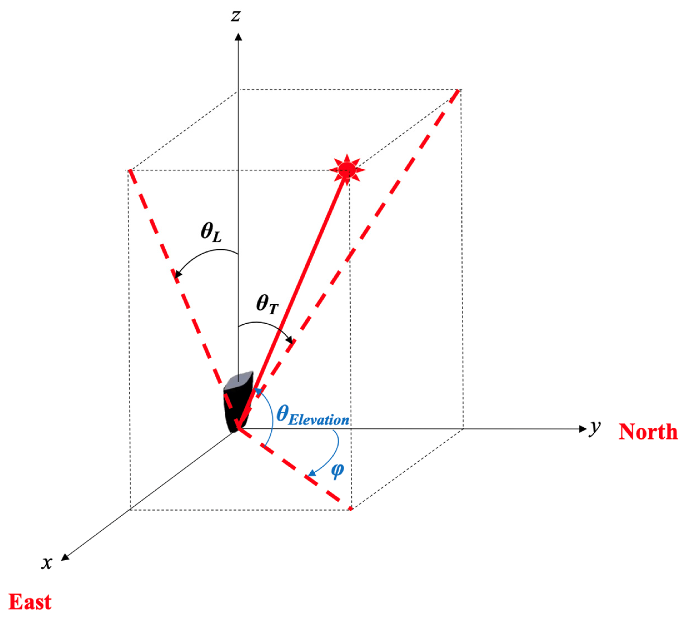
| φ | Solar azimuth angle |
| θElevation | Solar elevation angle |
| θL (°) | Longitudinal angle of the solar incident rays |
| θT (°) | Transversal angle of the solar incident rays |
References
- Solar Energy Basics, National Renewable Energy Laboratory. Available online: https://www.nrel.gov/research/re-solar.html (accessed on 23 June 2023).
- Plytaria, M.; Bellos, E.; Tzivanidis, C.; Antonopoulos, K. Numerical simulation of a solar cooling system with and without phase change materials in radiant walls of a building. Energy Convers. Manag. 2019, 188, 40–53. [Google Scholar] [CrossRef]
- Goel, V.; Bhattacharyya, S.; Kumar, R.; Pathak, S.; Tyagi, V.; Saini, R. Identification of barriers and drivers to implementation of solar drying technologies. J. Therm. Anal. Calorim. 2023, 148, 2977–3000. [Google Scholar] [CrossRef]
- Mawire, A.; Lentswe, K.; Owusu, P.; Shobo, A.; Darkwa, J.; Calautit, J.; Worall, M. Performance comparison of two solar cooking storage pots combined with wonderbag slow cookers for off-sunshine cooking. Sol. Energy 2020, 20, 1166–1180. [Google Scholar] [CrossRef]
- CNET. Most Efficient Solar Panels of January 2024. Available online: https://www.cnet.com/home/energy-and-utilities/most-efficient-solar-panels/ (accessed on 10 January 2024).
- Concentrating Solar-Thermal Power Basics, American Office of Energy Efficiency & Renewable Energy. Available online: https://www.energy.gov/eere/solar/concentrating-solar-thermal-power-basics (accessed on 23 June 2023).
- Leonardi, M.; Lombardo, S. Effects of Module Temperature on the Energy Yield of Bifacial Photovoltaics. Energies 2022, 15, 22. [Google Scholar] [CrossRef]
- Lu, Z.; Zhao, Y. Performance investigation of a concentrated photovoltaic-thermoelectric hybrid system for electricity and cooling production. Appl. Therm. Eng. 2023, 231, 120916. [Google Scholar] [CrossRef]
- Winston, R.; Juan, C.; Beni, P. Non-Imaging Optics; Elsevier Academic Press: Cambridge, UK, 2005. [Google Scholar]
- Huang, Y.; Ma, X.; Rao, C.; Liu, X.; He, R. An annular compound parabolic concentrator used in tower solar thermal power generation system. Sol. Energy 2019, 188, 1256–1263. [Google Scholar] [CrossRef]
- Lipiński, W.; Steinfeld, A. Annular Compound Parabolic Concentrator. J. Sol. Energy Eng. 2006, 128, 121–124. [Google Scholar] [CrossRef]
- Li, L.; Wang, B.; Pye, J.; Lipiński, W. Temperature-based optical design, optimization, and economics of solar polar-field central receiver systems with an optional compound parabolic concentrator. Sol. Energy 2020, 206, 1018–1032. [Google Scholar] [CrossRef]
- Faye, K.; Thiam, A.; Faye, M.; Craig, K.; Cissé, E.; Sambou, V. Temperature estimation of a receiver equipped with a 3D compound parabolic concentrator. Appl. Therm. Eng. 2023, 222, 119916. [Google Scholar] [CrossRef]
- Prabhat, B.D.; Ganapathiraman, S.; Manikam, P. Design procedure of stationary compound parabolic concentrator with flat plate absorber for effective year-round performance—Response Surface Methodology and Tracepro as tools. Clean. Energy Syst. 2023, 5, 100074. [Google Scholar] [CrossRef]
- Liu, Y.; Gui, Q.; Xiao, L.; Zheng, C.; Zhang, Y.; Chen, F. Photothermal conversion performance based on optimized design of multi-section compound parabolic concentrator. Renew. Energy 2023, 209, 286–297. [Google Scholar] [CrossRef]
- Liu, H.; Zhang, J.; Pei, M.; Ju, X.; Xu, C. Optical, electrical, and thermal performance enhancement for a concentrating photovoltaic/thermal system using optimized polynomial compound parabolic concentrator. Appl. Energy 2024, 358, 122596. [Google Scholar] [CrossRef]
- Gao, C.; Chen, F. Model building and optical performance analysis on a novel designed compound parabolic concentrator. Energy Convers. Manag. 2020, 209, 112619. [Google Scholar] [CrossRef]
- Paul, D. Optical performance analysis and design optimization of multisectioned compound parabolic concentrators for photovoltaics application. Int. J. Energy Res. 2018, 43, 358–378. [Google Scholar] [CrossRef]
- Duffie, J.; Beckman, W. Solar Engineering of Thermal Processes, 2nd ed.; Madison: New York, NY, USA; John Wiley & Sons: Hoboken, NJ, USA, 2013. [Google Scholar] [CrossRef]
- Cooper, T.; Dähler, F.; Ambrosetti, G.; Pedretti, A.; Steinfeld, A. Performance of compound parabolic concentrators with polygonal apertures. Sol. Energy 2013, 95, 308–318. [Google Scholar] [CrossRef]
- Garcia-Botella, A.; Fernandez-Balbuena, A.; Bernabeu, E. Elliptical concentrators. Appl. Opt. 2006, 45, 7622–7627. [Google Scholar] [CrossRef] [PubMed]
- Sellami, N.; Mallick, T.; McNeil, D. Optical characterization of 3-D static solar concentrator. Energy Convers. Manag. 2012, 64, 579–586. [Google Scholar] [CrossRef]
- Ali, I.; O’Donovan, T.; Reddy, K.; Mallick, T. An optical analysis of a static 3-D solar concentrator. Sol. Energy 2013, 88, 57–70. [Google Scholar]
- Alomar, O.; Ali, O.; Ali, B.; Qader, V.; Ali, O. Energy, exergy, economical and environmental analysis of photovoltaic solar panel for fixed, single, and dual axis tracking systems: An experimental and theoretical study. Case Stud. Therm. Eng. 2023, 51, 103635. [Google Scholar] [CrossRef]
- Wu, C.; Wang, H.; Chang, H. Dual-axis solar tracker with satellite compass and inclinometer for automatic positioning and tracking. Energy Sustain. Dev. 2022, 66, 308–318. [Google Scholar] [CrossRef]
- Ontiveros, J.; Ávalos, C.; Loza, F.; Galán, N.; Rubio, G. Evaluation and design of power controller of two-axis solar tracking by PID and FL for a photovoltaic module. Int. J. Photoenergy 2020, 2020, 8813732. [Google Scholar] [CrossRef]
- Vaidya, N.; Solgaard, O. Immersion graded index optics: Theory, design, and prototypes. Microsyst. Nanoeng. 2022, 8, 69. [Google Scholar] [CrossRef] [PubMed]
- Dassault Systems, SolidWorks. Available online: https://www.solidworks.com/ (accessed on 11 January 2024).
- Lambdares. TracePro Ray Tracing Simulation Software, LC 2022. Available online: https://lambdares.com/tracepro/ (accessed on 11 January 2024).
- Pujol-Nadal, R.; Cardona, G. OTSunWebApp: A ray tracing web application for the analysis of concentrating solar-thermal and photovoltaic solar cells. SoftwareX 2023, 23, 101449. [Google Scholar] [CrossRef]
- Casio, Keisan. Daily Variation of the Solar Angles. Available online: https://keisan.casio.jp/exec/system/1185781259 (accessed on 11 January 2024).


| α0° | 15° | 30° | 45° |
|---|---|---|---|
| H/d0° | 9.1 | 2.6 | 1.2 |
| α90°= 10° | 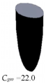 |  | 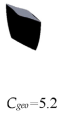 |
| α90°= 20° |  |  | |
| α90°= 30° |  |
| α0° | 15° | 30° | 45° |
|---|---|---|---|
| H/d0° | 9.1 | 2.6 | 1.2 |
| α90°= 10° | 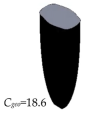 |  |  |
| α90°= 20° |  |  | |
| α90°= 30° |  |
Disclaimer/Publisher’s Note: The statements, opinions and data contained in all publications are solely those of the individual author(s) and contributor(s) and not of MDPI and/or the editor(s). MDPI and/or the editor(s) disclaim responsibility for any injury to people or property resulting from any ideas, methods, instructions or products referred to in the content. |
© 2024 by the authors. Licensee MDPI, Basel, Switzerland. This article is an open access article distributed under the terms and conditions of the Creative Commons Attribution (CC BY) license (https://creativecommons.org/licenses/by/4.0/).
Share and Cite
Mboup, A.; Akisawa, A.; Pujol-Nadal, R.; Martínez-Moll, V. Design and Optical Performance Evaluation of the Three-Dimensional Solar Concentrators with Multiple Compound Parabolic Profiles and Elliptical and Rectangular Receiver Shapes. Energies 2024, 17, 721. https://doi.org/10.3390/en17030721
Mboup A, Akisawa A, Pujol-Nadal R, Martínez-Moll V. Design and Optical Performance Evaluation of the Three-Dimensional Solar Concentrators with Multiple Compound Parabolic Profiles and Elliptical and Rectangular Receiver Shapes. Energies. 2024; 17(3):721. https://doi.org/10.3390/en17030721
Chicago/Turabian StyleMboup, Aïssatou, Atsushi Akisawa, Ramón Pujol-Nadal, and Víctor Martínez-Moll. 2024. "Design and Optical Performance Evaluation of the Three-Dimensional Solar Concentrators with Multiple Compound Parabolic Profiles and Elliptical and Rectangular Receiver Shapes" Energies 17, no. 3: 721. https://doi.org/10.3390/en17030721
APA StyleMboup, A., Akisawa, A., Pujol-Nadal, R., & Martínez-Moll, V. (2024). Design and Optical Performance Evaluation of the Three-Dimensional Solar Concentrators with Multiple Compound Parabolic Profiles and Elliptical and Rectangular Receiver Shapes. Energies, 17(3), 721. https://doi.org/10.3390/en17030721