Article

Efficiency Improvement of Permanent Magnet Synchronous Motors Using Model Predictive Control Considering Core Loss

1
School of Electrical and Data Engineering, University of Technology Sydney, Sydney, NSW 2007, Australia
2
School of Automation and Electrical Engineering, University of Science and Technology of Beijing, Beijing 100081, China
3
School of Electrical and Information Engineering, The University of Sydney, Sydney, NSW 2006, Australia
*
Authors to whom correspondence should be addressed.
Energies 2024, 17(4), 773; https://doi.org/10.3390/en17040773
Submission received: 21 December 2023 / Revised: 15 January 2024 / Accepted: 27 January 2024 / Published: 6 February 2024
(This article belongs to the Special Issue Energy Management and Optimization for New Power Systems)

Abstract

:
The highway cycle is an important consideration in the EV’s new European driving cycles (NEDCs) range, as the steady-state efficiency improvement in such conditions can be greatly beneficial. In the model predictive control (MPC) of the permanent magnet synchronous motors (PMSMs), the predicted next-step feedback reference generated by the equivalent circuit model (ECM) will contribute directly to the voltage vector selection, therefore influencing the performance of the motor control. In the current MPC scheme, when the conventional ECM is applied, it only considers copper loss, and the core loss is usually disregarded. In some circumstances, such as the highway cycle of EVs, the motors are at high speed, the torque is low, and the core loss can be significant in the losses, thus affecting the accuracy of control and the efficiency of the system; hence, the introduction of core loss ECM into the MPC would be beneficial. This paper aims to investigate the steady-state efficiency improvement of a novel ECM of PMSM considering core loss ECM, and the comparison will be based on model predictive direct torque control (MPDTC) using the core loss ECM, which will be compared to MPDTC with the conventional ECM of the PMSM. The results demonstrate the proposed ECM’s efficiency improvement in various conditions, the limitations of the model and the simulation are discussed, and future work is proposed.

1. Introduction

With the booming of the electric vehicle (EV) industry in recent years, the application of drive systems has grown more demanding. The choosing of a motor is one of the most important parts of designing a drive system, and the selection of motors comes from the four major types [1]—DC, induction, switched reluctance (SR) [2], and permanent magnet (PM) brushless (BL) drives. The requirements for the motor focus on the following [1]:
(1)
Reliability and robustness;
(2)
Torque and power density;
(3)
Dynamic performance;
(4)
Very wide speed range;
(5)
The energy efficiency of high-speed cruising.
Under such requirements, as part of PM BL drives, the permanent magnet synchronous motor (PMSM) demonstrates its strength compared to the brushed motor and induction motor. The PMSM is a common type of synchronous motor that is commonly used in the modern world, and its rotor structure contains permanent magnets that provide a magnetic field in the motor. Its benefits include less copper material for winding, less copper loss, and higher power density, as well as high torque density [1,3]. It is widely applied in real life and is emerging with its wide application into the field of electric vehicles [4,5].

1.1. Gap and Motivation

One of the most important characteristics that manufacturers are promoting in their modern EVs and using to compete with others is the travel range of EVs under the Worldwide Harmonized Light-Duty Test Procedure (WLTP) drive cycle, or new European driving cycles (NEDCs) [6]. These are the standards that define different driving conditions; under NEDC, the highway cycle is investigated. In this particular driving condition, the EV is traveling at a constant high speed, the torque is relatively low as there is only road friction and wind drag to overcome, and the motor tends to be in a higher speed, but lower torque operation condition [7]. The study of efficiency improvement under such working conditions can benefit the range and is the focus of this research.
In this paper, a brief literature review of the existing MPDTC strategy is discussed. The differences between the conventional ECM and the core loss ECM are explained, as well as the circumstances in which core loss could be significant and hard to neglect. In such scenarios, the difference and importance of the core loss ECM are demonstrated, hence revealing the research gap in improving the steady-state efficiency of MPDTC by using a better-described core loss ECM [8]. In this study, the accuracy of the core loss ECM and its robustness are not the focus of the study—the study focuses on the efficiency improvement produced by applying the core loss ECM to MPDTC. It is discussed by comparing the simulation results between using MPDTC with the conventional ECM and using MPDTC with the core loss ECM. The EV’s highway cycle is the focus—in this circumstance, the motor is on high speed and underloaded, and the corresponding LMA is applied to help with flux weakening. In addition, the nominal load and overload performance are included and briefly discussed.

1.2. Literature Review

Regarding the control method, the popular control methods for PMSM are field-oriented control (FOC) and direct torque control (DTC). They have their strengths, however, compared to the application of the MPC in EVs, their shortcomings are obvious—for instance, the FOC will require fine-tuning of parameters, and DTC does not have good efficiency performance [9]. Also, when comparing the hardware losses, such as the sampling frequency, flux, and torque ripple, the model predictive control (MPC) has significant strength compared to them both [10,11]. This study will base itself on the MPC, and the performances of FOC and DTC will not be further discussed.
While the conventional PMSM motor control algorithms use the conventional equivalent circuit model (ECM), they tend to disregard core losses, and this makes sense in low-speed motors with low pole numbers [8]. However, a more described model of PMSM considering core loss can benefit motor control greatly and should be considered in some applications, for instance, when the motor is at its high-speed range [12,13], or when there is a special design used in the core material—such as Soft Magnetic Composite (SMC) material [14,15]—as the core loss may overtake copper loss as the dominant loss in the motor. The difference of the ECM is particularly applicable in the MPC, as the MPC uses the mathematical model of the motor to produce next-step predictions [16,17]. The predicted performance characteristic of choices (usually two) [11,16] has the advantage of its timeliness over the measured and evaluated feedback from the motor. The timelier next-step feedback is closer to reality than the evaluated feedback from the past, and particularly in steady-state it can then be compared to the generated references, and the best voltage vector can be selected. Therefore, a more suitable voltage vector would be applied, thus improving efficiency [18].
The loss minimization algorithm (LMA) is equally important [19,20], and since the efficiency comparison between the MPDTC using the conventional ECM and the MPDTC using the core loss ECM needs to be concluded, there are a few simulation parameters that need to be kept constant, such as the motor parameters, the cost function parameters, and most importantly, the torque and flux references. The LMA in this circumstance can generate references that are relatively more consistent in different ECMs, therefore the results can be more easily compared to each other. However, since the ECM has been updated to the core loss ECM, there will be some changes in the LMA, despite the fact that they are both intended to minimize the power losses. In addition, the copper loss and core loss minimization algorithms are also discussed in this paper.

1.3. Research Method

1.3.1. Concept

The study presents an efficiency performance comparison between the conventional ECM model and the core loss ECM of PMSM, embedded in one-step-ahead prediction embedded in MPDTC. With the different ECMs, a separate LMA strategy will be considered as best practice with each ECM.

1.3.2. Assumptions

The comparison will be performed using linear models, and changes in the model parameters due to impacts, such as temperature, rotor position, coil current, and hysteresis of the material, are assumed to be non-effecting.

1.3.3. Description of the Tool

The efficiency of an IPMSM model with the core loss ECM is simulated using the Matlab/Simulink R2020a tool, and the core loss ECM was modeled and analyzed in a previous study [8].

1.3.4. Analysis Theme

Simulations under variable load and speed conditions have been conducted in this study. The efficiency of the system in different ECMs is calculated by shaft mechanical power divided by DC-link electrical power; they are then calculated to a percentage value so that they can be compared to each other under the same load and speed conditions.

1.3.5. Research Results

The efficiency of the drive system is growing to be of great importance to EV applications, especially when the EV travel range under NEDC and WLTP drive cycles are the direct marketing characteristics of EVs. The results presented in this study will show a percent of efficiency improvement of the MPDTC by adopting the core loss ECM in the one-step-ahead prediction used in the MPC, compared to the one adopting the conventional ECM, also applying the suited LMA for each ECM.

2. Application of Core Loss ECM in MPC and LMA Development

2.1. Equivalent Circuit Model with Core Loss

There are three main sources of losses in an electric motor, which are the mechanical loss from the friction of air and mechanical parts, the copper loss from coil resistance, and the core loss caused by the variation of the magnetic flux. The core losses can be further divided into three parts: hysteresis loss, eddy current loss, and anomalous loss or excess loss [21,22].
The hysteresis loss is usually considered to be in the stator core, as ideally the magnetic field of the rotor core does not change. The hysteresis loss is caused by the inherent B (magnetic flux density)–H (magnetic field strength) characteristic of the material [23]. When the core material’s magnetic field cycles through its B–H curve, the loss is created, and it can be expressed as [24]:
P h = K h f B m α
where  f  is the excitation frequency,  B m  is the magnitude of sinusoidal flux density, and  K h  and α are the coefficients of the hysteresis loss for the magnetic material.
When the magnetic flux alternates, the stator core induces back electromotive force (EMF), which then induces current, and therefore causes loss [25]. This loss is called eddy current loss, and the amount of loss depends on the resistance of the core and the physical parameters such as shape and size. When a high frequency is involved, for instance, the high-order harmonics—and, when at high speed, the skin effect—can increase the eddy current loss.
The eddy current loss is caused in the stator tooth and yoke, and there have been various studies that have analyzed the detail of the loss and provided the below equations [24].
P e d = K e ( f B m ) β
where  K e  and β (2 is often used) are the coefficients of the eddy current loss components.
Additional loss [24]:
P a = K a f 1.5 B m 1.5
where  K a  is the coefficient of the additional core loss component.
The core loss of PMSM can be obtained through multiple approaches, such as finite element analysis (FEA) and reluctance network analysis (RNA) [26]. The disadvantage is that the FEA will take professional software minutes to perform. This is not ideal when embedded into the control algorithm. The ECM can do fast estimation and will provide a good estimation of the losses in the motor and can work efficiently with the LMA.
There are a few variances of mathematical models that have included the core loss [27,28], and they have made advances in the aspect of obtaining a more detailed mathematical core loss model of PMSM [29,30]. In this paper, only one core loss ECM form is discussed, referred to the preferred core loss ECM [8,31].

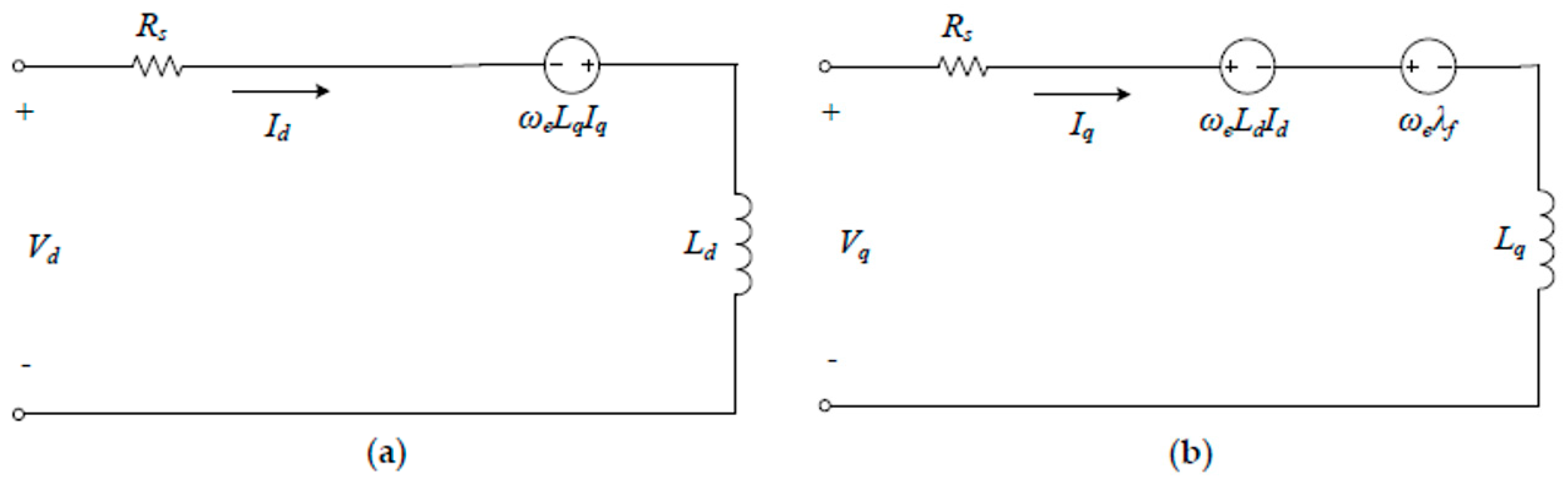
2.1.1. Conventional ECM of PMSM

The MPC relies on the ECM of the motor to generate a predictive equation. By mutating the equation, the next-step reference is generated. Taking the conventional ECM disregarding core loss as an example, the d-q frame equivalent circuit is shown in Figure 1 [8].
By applying Kirchhoff’s law, the following equations can be generated. Referring to Table 1 below for detailed descriptions of the components, and with  ω e  as the electrical speed (rad/s):
V d = R s I d ω e L q I q + d I d d t L d V q = R s I q + ω e L d I d + ω e λ f + d I q d t L q
By mutating the functions, we have
d I d = ( V d R s I d + ω e L q I q L d ) × d t d I q = ( V q R s I q ω e L d I d ω e λ f L q ) × d t
where  d I d = I d k + 1 I d k d I q = I q k + 1 I q k . Since the present  I d k , I q k  can be evaluated from feedback, and  d t  can simply be expressed as sampling time  T s , the predictive  I d k + 1  and  I q k + 1  can be expressed as:
I d k + 1 = ( V d R s I d + ω e L q I q ) × T s L d + I d k I q k + 1 = ( V q R s I q ω e L d I d ω e λ f ) × T s L q + I q k
Table 1. Parameters of an IPMSM.
Motor CharacteristicsSymbolValue
Number of pole pairs   p 4
Stator winding resistance   R s 0.0974 Ω
d-axis inductance   L d 83.955 μH
q-axis inductance   L q 328.365 μH
PM flux linkage   λ f 0.0479 Wb
Rated speed   N 3600 r/min
Rated current   I N 180 A
Rated power   P N 20 kW
Rated torque   T N 53 Nm
No-load equivalent core loss resistance   R c o 5.418 · 10 7 · n 2 + 0.005056 · n  Ω (n represents the motor speed)
Load equivalent core loss resistance   R c i 21 Ω

2.1.2. Core Loss Equivalent Circuit Model of PMSM

There are a number of different variations of the core loss ECM that have been discussed in the literature [8], and the preferred core loss ECM is demonstrated in Figure 2.
The power losses in PMSM contain the copper and core losses, mechanical losses, and additional losses. Where additional loss is related to both copper and core components, it is normally estimated as a percentage of rated power. The losses can be categorized into controllable and uncontrollable losses. The copper losses are mainly determined by the fundamental harmonic component of the stator current, and the core losses, mostly from the harmonic component of the total linkage flux, are controllable. Copper and core losses from higher-frequency harmonics, together with mechanical losses, are uncontrollable losses [32].
The below, Figure 2a,b, demonstrate the preferred core loss ECM [8].
Figure 2. Preferred equivalent circuits of PMSM including core loss. (a) d-axis. (b) q-axis.
Energies 17 00773 g002
By applying Kirchhoff’s law, the mathematical equation of the above core loss ECM is obtained:
V d V q = R s + p L d ω e L q ω e L d R s + p L q I d I q + ω e λ f 0 1
By mutating the functions, we also have:
I d k + 1 = ( V d R s I d + ω e L q I q ) × T s L d + I d k I q k + 1 = ( V q R s I q ω e L d I d ω e λ f ) × T s L q + I q k
The difference is that we will need to evaluate the actual current in the motor besides the core loss current, thus:
I d = I c i d + I m d I q = I c i q + I m i q = I c o + I m q
I c i d = ω e L q I q R c o I c o = ω e λ f R c o
I m d k + 1 = ( V d R s I d + ω e L q I q ) × T s L d + I d k ω e L q I q R c o I m q k + 1 = ( V q R s I q ω e L d I d ω e λ f ) × T s L q + I q k ω e λ f R c o

2.1.3. Determination of Core Loss Resistances

To perform an estimation of the core loss resistance values in the ECM, the core losses are obtained mainly in two ways.
  • Simulation and calculation based on the finite element method and professional software. It constructs the relationships between the core power loss and the flux densities and the load currents to construct separate curves. And then evaluate the load equivalent core loss resistances as constants or variables concerning some parameters like speed [33,34].
  • Experimental tests following similar procedures as above, but all data are acquired through the experimental tests on the prototype [35,36].
The motor to be used in the simulation is an interior PMSM (IPMSM), and the motor and core loss parameters are listed below.

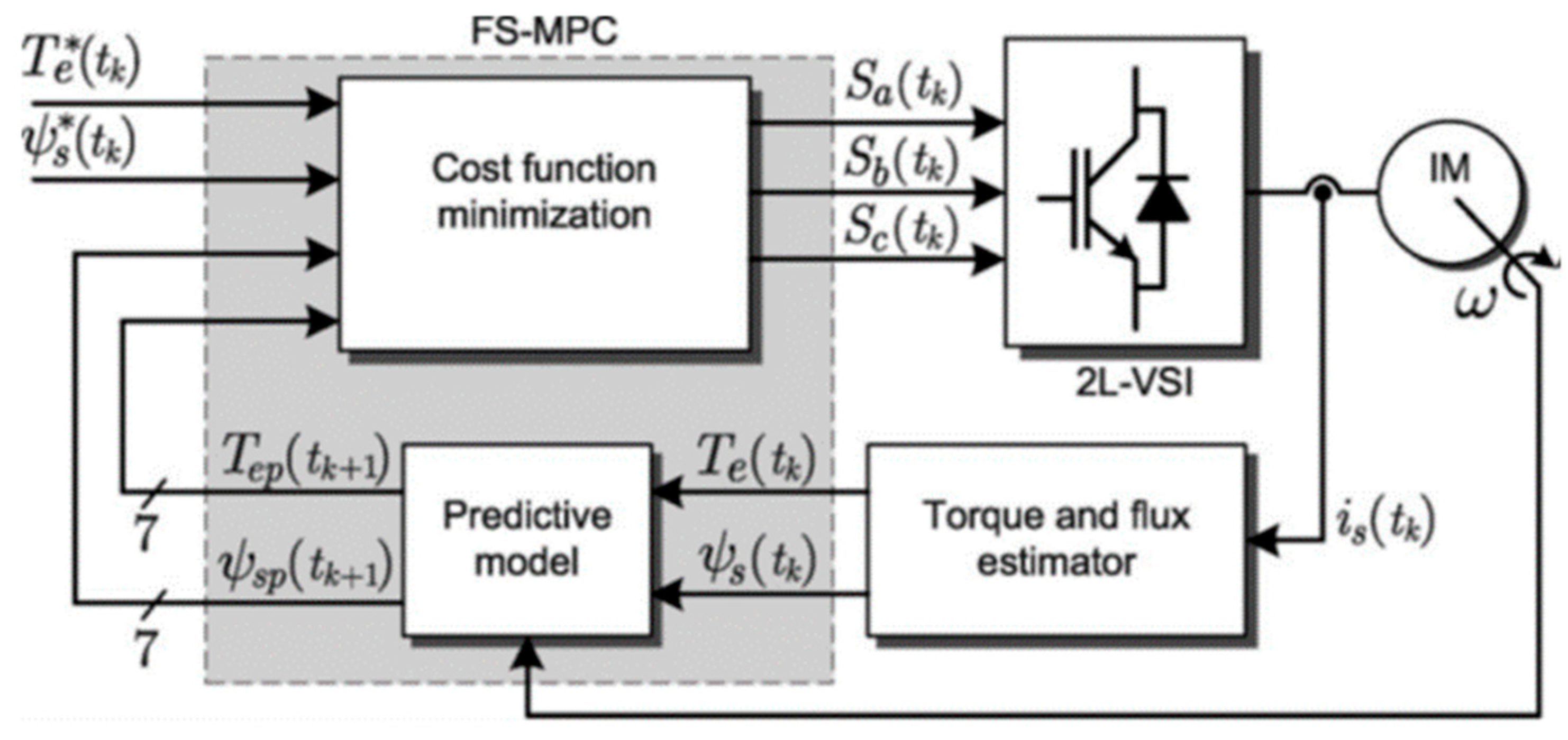
2.2. Model Predictive Direct Torque Control (MPDTC)

The model predictive control (MPC) was introduced as an advanced control method back in the 1970s. It is a control method that relies on the ECM of the motor to predict the motor movement dynamics with its feedback and compare it to the reference accordingly. In this way, the control algorithm can use the feedback more closely to the actual movement when engaging close-loop control, therefore achieving better performance in the control [37].
MPC can be in different forms, depending on its principle, controlling target, and algorithm. In this paper, the variant of MPC in discussion is based on flux and torque. As shown below in Figure 3, with the feedback speed error to compute the torque reference, using the LMA calculation, the flux and torque references are generated. They are then brought to the cost function calculation with the next-step predicted flux and torque, calculated from all the possible voltage vectors. The results in the calculated cost function, the “g” values in (12), correspond to each voltage vector. By comparing the cost function calculation results, the lowest “g” result voltage vector can be selected as the best response. The finite control set MPC (FCS-MPC) is simple in design and calculation, which therefore improves the response time. In regard to its selection of space vectors, with one-step ahead prediction only seven vectors will need to be considered, as in Table 2, V0 and V7 are null, therefore improving the response [38].
As previously mentioned, the cost function of FCS-MPC is the key to model predictive control, as in the following Equation (12), while the MPDTC uses the torque and flux as references. The  λ ψ  is the weighting factor design for torque and flux control, and it can be used to define the weighting of the flux and torque components in the cost function, and contribute directly to the selection of the vectors:
g = T e T e + λ ψ ψ e ψ e
where  λ ψ  is the weighting factor for flux and torque, which needs to be able to handle the difference in magnitude and unit between flux and torque;  T e  and  ψ e  are the reference torque and flux, separately; and  T e  and  ψ e  are the evaluated torque and flux responding to different voltage vectors.
According to the calculation results in (6) and (11), the predictive  I d k + 1  and  I q k + 1  have been evaluated in the conventional ECM, as well as the predictive  I m d k + 1 , and  I m q k + 1  in the core loss model. The equations have components  V d , and  V q , which are the voltages that are dynamic and controlled by the IGBT gates, as in Table 2. The different voltage vectors are used to produce the predicted currents, therefore generating predicted characteristics that are to be compared to the references. The voltage vector that provides the lowest cost function result is selected, and then be modulated to the application, realizing the control modulation.

2.3. Loss Minimization Algorithm (LMA)

2.3.1. Conventional ECM

With the conventional ECM as in Figure 1, the losses can be derived. Since the core losses are disregarded, the overall controllable copper loss can be expressed with the below equations:
P c u = 3 2 R s I d 2 + I q 2
The electromagnetic torque  T e m  is:
T e m = 3 2 p λ f I q + L d L q I d I q
mutating the equation, one has:
I q = T e m p ( λ f + L d L q I d L d L q I d )
therefore:
P c u = 3 2 R s I d 2 + ( T e m p ( λ f + L d L q I d L d L q I d ) ) 2
To achieve the minimum loss, the derivative of total controllable loss to  i d  is set to 0.
P c u I d = 0
Use Matlab to solve the below equation for  I d r e f , so that the reference characteristic can be generated to be used for the control reference.
r o o t [ 3 L d 2 L q p 2 3 L d L q 2 p 2 + L q 3 p 2 z 4 + 6 L d L q p 2 λ f 3 L q 2 p 2 λ f 3 L d 2 p 2 λ f z 3 + 3 L q p 2 λ f 2 3 L d p 2 λ f 2 z 2 + p 2 λ f 3 z + L d T e m 2 , z , 1 ]
Select the real solution with the smallest magnitude, and calculate  I q r e f  from Equation (15). Hence, we can calculate the flux and torque reference for the control strategy, as in Figure 3.
φ r e f = L d I d r e f + λ f 2 + L q I q r e f 2 T r e f = 3 2 p λ f I q r e f + L d L q I d r e f I q r e f

2.3.2. Conventional ECM

In the core loss model, in addition to the copper loss, there is also core loss to be considered. The expression of the loss in the preferred model in no-load and loaded conditions can be expressed as below, separately:
The core loss power for no-load conditions— P c o —can be expressed as:
P c o = 3 2 R c o I c o 2 = 3 2 ( ω e λ f ) 2 1 R c o
the core loss power for loaded conditions— P c i —can be expressed as:
P c i = P c o + 3 2 R c i I c i d 2 + I c i q 2 = P c o + 3 2 ω e L q I q 2 R c i + ω e L d I d 2 R c i
since the simulation is under loaded conditions,
P c o r e = P c i = 3 2 ( ω e λ f ) 2 1 R c o + 3 2 ω e L q I q 2 R c i + ω e L d I d 2 R c i
Therefore, the total controllable loss  P L = P c u + P c o r e . To achieve the minimum loss, the derivative of the total controllable loss to  I m d  is set to 0.
P L = 3 2 R s I d 2 + ( T e m p ( λ f + L d L q I d L d L q I d ) ) 2 + 3 2 ( ω e λ f ) 2 1 R c o + 3 2 ω e L q I q 2 R c i + ω e L d I d 2 R c i
the evaluation of the function includes (6) and (7):
To achieve the minimum loss, the derivative of the total controllable loss to  I m d  is set to 0.
P L I m d = 0
Use Matlab to solve the below equation for  I m d r e f , so that the reference characteristic can be generated to be used for the control reference.
r o o t [ ( 9 L d 3 L q 2 R c i R c o N 2 p 4 π 2 3 L d 2 L q 3 R c i R c o N 2 p 4 π 2 9 L d 4 L q R c i R c o N 2 p 4 π 2 + 3 L d 5 R c i R c o N 2 p 4 π 2 5400 L d 2 L q R c i 2 R c o R s p 2 + 5400 L q 2 L d R c i 2 R c o R s p 2 1800 L q 3 R c i 2 R c o R s p 2 + 1800 L d 3 R c i 2 R c o R s p 2 ) z 4 + ( 18 L d 3 L q R c i R c o N 2 p 4 π 2 λ f + 9 L d 2 L q 2 R c i R c o N 2 p 4 π 2 λ f 10,800 L d L q R c i R s p 2 λ f + 9 L d 4 R c i R c o N 2 p 4 π 2 λ f + 5400 L q 2 R c i 2 R c o R s p 2 λ f + 5400 L d 2 R c i 2 R c o R s p 2 λ f ) z 3 + ( 9 L d 2 L q R c i R c o N 2 p 4 λ f 2 π 2 + 9 L d 3 R c i R c o N 2 p 4 λ f 2 π 2 5400 L q R c i 2 R c o R s p 2 λ f 2 + 5400 L d R c i 2 R c o R s p 2 λ f 2 ) z 2 + ( 60 L d L q R c i R c o R s T e m N p 2 λ f π + 60 L q 2 R c i R c o R s T e m N p 2 λ f π + 120 L d L q R c i 2 R s T e m N p 2 λ f π 60 L q 2 R c i 2 R s T e m N p 2 λ f π 60 L d 2 R c i 2 R s T e m N p 2 λ f π + 3 L d 2 R c i R c o N 2 p 4 λ f 3 π 2 + 1800 R c i 2 R c o R s p 2 λ f 3 ) z 60 L q R c i R c o R s T e m N p 2 λ f 2 π + 60 L q R c i 2 R s T e m N p 2 λ f 2 π 60 L d R c i 2 R s T e m N p 2 λ f 2 π 2 L d L q 2 R c o R s T e m 2 N 2 p 2 π 2 + 3 L d L q 2 R c i R c o T e m 2 N 2 p 2 π 2 + 2 L q 3 R c o R s T e m 2 N 2 p 2 π 2 + 3 L q 3 R c i R c o T e m 2 N 2 p 2 π 2 + 1800 L q R c i 2 R c o R s T e m 2 1800 L d R c i 2 R c o R s T e m 2 ,   z ,   1 ]
Similarly, use Equations (15) and (19) to generate the flux and torque references  φ r e f  and  T r e f .

3. Simulation Results

3.1. Comparison Scheme

In the simulation comparison, there are constant parameters and variable parameters that need to be pre-defined to achieve reasonable results. The following parameters are kept constant across the comparison, they are not necessarily the optimal value for the best performance, but for the purpose of performance comparison to each simulation strategy, as in Table 3.
During the simulation, the cost function is applied as in (12), the norms selected for the control are torque and flux, and the weighting factor of the components  λ ψ  is selected as 1. The PID loop for torque reference generation is also kept the same, the proportional gain is 0.5, and the integral gain is 0.5. The gain values are kept the same across all three simulation sets. The simulation blocks are as demonstrated below in Figure 4, corresponding to the content discussed from Section 2, Section 3 and Section 4, and as shown in Figure 3.
The variable parameters of the simulation are the mathematical model included in the design and the reference generation LMA strategies. By combining the variables, there are three sets of simulations that are performed, as explained in Table 4. The simulations are performed at 1000 rpm to 5000 rpm, with observations taken during the steady state; repeated at each 1000 rpm increment; then repeated at different torques, 20 Nm and 40 Nm.

3.2. Simulation Results

3.2.1. Under Load

The steady-state performance of “MPDTC with core loss ECM and LMA based on the core loss and copper loss” at 20 Nm and 5000 rpm is shown below in Figure 5.
The below Table 5, Table 6 and Table 7 show the efficiency results of the simulations. The shaft output voltage is calculated by multiplying the simulated shaft speed and shaft torque.
P s h a f t = 2 π 60 N s h a f t · T s h a f t
In the equation,  N s h a f t  is the shaft speed in rpm, and  T s h a f t  is the shaft torque in Nm.
The input power is calculated with the DC supply of the inverter:
P D C = V D C · I D C
V D C  is the DC voltage of the inverter supply, and  I D C  is the current of the DC inverter supply. The efficiency— η —is calculated by:
η = P s h a f t P D C · 100 %
Table 5. Steady-state efficiency of MPDTC with core loss ECM with copper loss LMA simulation.
MPDTC with Conventional Loss ECM with Copper Loss LMA
Ref Speed
(rpm)
Torque
(Nm)
Shaft Output Power (W)Copper Loss
(W)
DC Power (W)Efficiency (%)
1000202093632.6347360.26%
2000204189641.9627266.79%
3000206284661896070.13%
4000208378679.111,42073.36%
50002010,470695.713,82075.76%
10004041823764834050.14%
2000408377383513,13063.80%
30004012,570391417,62071.34%
40004016,760399822,18075.56%
50004020,950403826,49079.09%
The improvement comparison is calculated in percentage using the efficiencies of strategies 2 and 3, based on the efficiency of strategy 1.
η 2 1 = η s t r a t e g y 2 η s t r a t e g y 1 1
similarly,
η 3 1 = η s t r a t e g y 3 η s t r a t e g y 1 1
Table 6. Steady-state efficiency of MPDTC with core loss ECM with copper loss LMA.
MPDTC with Core Loss ECM with Copper Loss LMAImprovement Compared to MPDTC with Conventional ECM (%)
Ref Speed
(rpm)
Torque
(Nm)
Shaft Output Power (W)Copper Loss
(W)
Core Loss (W)DC Power (W)Efficiency (%)
1000202093425.6138.4293971.21%18.17%
2000204190420.7322.6507282.61%23.69%
3000206285426569.3737085.28%21.59%
4000208380411.5904.5996584.09%14.63%
50002010,480392.9138312,51083.77%10.58%
10004041831445149.2767954.47%8.63%
2000408378146736711,42073.36%14.99%
30004012,570145766716,71075.22%5.45%
40004016,7601438107620,97079.92%5.77%
50004020,9501416164525,70081.52%3.07%
Table 7. Steady-state efficiency of MPDTC with core loss ECM and LMA based on the core loss and copper loss.
MPDTC with Core Loss ECM and LMA Based on the Core Loss and Copper LossImprovement Compared to MPDTC with Conventional ECM (%)
Ref Speed
(rpm)
Torque
(Nm)
Shaft Output Power (W)Copper Loss
(W)
Core Loss (W)DC Power (W)Efficiency (%)
1000202093425.7138.4294271.14%18.05%
2000204190420.9322.5505882.84%24.03%
3000206285426.4568.8736785.31%21.64%
4000208380411.590310,01083.72%14.11%
50002010,480394.6138012,48083.97%10.84%
10004041831445149.2766154.60%8.89%
20004083781467366.311,42073.36%14.99%
30004012,5701459663.716,71075.22%5.45%
40004016,7601443106620,97079.92%5.77%
50004020,9501426162425,71081.49%3.03%
The efficiency information in Table 7 and Table 8 can be expressed as a diagram, as in below Figure 6 and Figure 7, for clearer demonstration.
As observed from the results in Table 6 and Table 7, there is constant improvement in efficiency when the core loss model is applied to the MPDTC across both strategies 2 and 3. Strategy 2 has 12.66% on average, and strategy 3 has 12.68% improvement over strategy 1.

3.2.2. Nominal Load

At nominal load of the motor, 3600 rpm and 53 Nm torques, 4.1% improvement is found with strategy 3 compared to strategy 2, as shown in Table 8 below.
Table 8. Steady-state efficiency comparison between the MPDTC with the conventional ECM with copper loss LMA and the core loss ECM with LMA based on the core loss and copper loss on nominal loads.
Ref Speed
(rpm)
Torque
(Nm)
Shaft Output Power (W)Copper Loss
(W)
Core Loss (W)DC Power (W)Efficiency (%)Improvement Compared to MPDTC with Conventional ECM (%)
MPDTC with conventional loss ECM with copper loss LMA
36005320,0702398 26,79074.92
MPDTC with core loss ECM and LMA based on the core loss and copper loss
36005319,9902311993.525,63077.994.1

3.2.3. Overload

At 5000 rpm and 80 Nm, saturation is found in both the strategy 1 and 3 simulations, the motors are not able to reach the reference speed, and the torque ripple increases significantly when we compare the contents of Figure 8—below—to Figure 5. The copper loss and core loss are no longer able to be calculated as they are ramping up, as shown in Figure 9. The simulated results in strategy 1 under overload condition are recorded in Table 9, and the results in strategy 3 under overload condition are recorded in Table 10.

4. Discussion and Conclusions

This paper has presented the efficiency improvement of modified MPDTC with core loss models through simulation. Obvious improvement can be observed in Figure 6 and Figure 7 in the range when motor speed is high and torque is low, described as EVs’ highway cycle. The improvement is larger when the torque is lower, at 20 Nm; this makes sense, as at lower torques the current is smaller, and therefore the copper loss is smaller in proportion, hence the core loss model can better improve the efficiency. The simulation does not show strength in managing the core loss components using the core loss LMA. When comparing strategy 2 to strategy 3, while the LMA in strategy 3 also includes the core loss component in minimization, the performances do not clearly differ. The reasons for this result are likely due to the relevant component ( I d 2 + I q 2 ) in (13), which has been considered in copper loss LMA. While in (22), the current component of the core loss is ( ω e L q I q 2 R c i + ω e L d I d 2 R c i ), these are very similar equations. Their only differences are in the components of  L q  and  L d , the differences are not obvious. In the core loss model, the most effective component that would have impact on the core loss is the speed, as in (20), (21), both  P c o  and  P c i  have the component  ω e 2 , which, as well as being reduced by the value of  R c o , is also reduced by increases in speed.
In conclusion, the simulation confirms the expectation that the steady-state efficiency of MPDTC is improved by an ECM that considers core loss. The simulation and calculation results demonstrated that the core loss ECM has more than 10% efficiency improvement at 5000 rpm/20 Nm, and more than 3% efficiency improvement at 5000 rpm/40 Nm, despite the LMA approaches applied, under a reasonable description of an EV running through its highway cycle. In nominal duty, there is 4.1% improvement in efficiency, and constant improvement when the motor’s work condition runs to the flatter side of the B–H curve until saturation.
The limitations of the research involve the robustness of the core loss ECM, and the lack of evidence from real-life experiments. In the simulation, a salient IPMSM is used, and its high pole pair number and core material made the core loss component optimization more visible. When a less salient PMSM with a smaller  L d  and  L q  difference is applied, the accuracy of the LMA could be impacted negatively according to (16) and (23). Also, when applied to a surface-mounted PMSM, to work with its equal  L d  and  L q  value, the algorithm has to be re-designed with per-phase ECM, and the performance improvement cannot be concluded at this stage. The inductance and resistance of the ECM may also be impacted by temperature and motor saturation, impacting the accuracy of the mathematical model, and therefore undermining the transient and steady-state performance. In this case, a sliding mode observer (SMO) or its variant can be introduced to improve the robustness to disturbances and uncertainties [11,39].
Real-life experiments need to be conducted to confirm the performance improvement. Ideally, the MPDTC with core loss model should provide a more realistic voltage vector selection based on the prediction, however, the LMA and MPC increase calculation volume. Since the capacity of the CPU is limited, the negative influence can increase the delay to the control, or the switching frequency may be reduced, therefore reducing the performance. The future work of this study is to investigate the impacts of different disturbances and uncertainties on the core loss mathematical model, to make the design more robust to PMSMs, and to become able to implement and demonstrate improvement in real-life experiments.

Author Contributions

Conceptualization, Y.G., X.B. and J.Z.; Software, L.H. and Y.G.; Validation, G.L.; Formal analysis, L.H.; Investigation, L.H. and X.B.; Resources, X.B.; Data curation, G.L.; Writing—original draft, L.H.; Writing—review & editing, Y.G.; Supervision, Y.G., G.L. and J.Z.; Project administration, Y.G. All authors have read and agreed to the published version of the manuscript.

Funding

This research received no external funding.

Data Availability Statement

Data are contained within the article.

Conflicts of Interest

The authors declare no conflict of interest.

References

  1. Chau, K.T.; Chan, C.C.; Liu, C. Overview of Permanent-Magnet Brushless Drives for Electric and Hybrid Electric Vehicles. IEEE Trans. Ind. Electron. 2008, 55, 2246–2257. [Google Scholar] [CrossRef]
  2. Kiyota, K.; Chiba, A. Design of Switched Reluctance Motor Competitive to 60 kW IPMSM in Third Generation Hybrid Electric Vehicle. IEEE Trans. Ind. Appl. 2012, 48, 2303–2309. [Google Scholar] [CrossRef]
  3. Gu, W.; Zhu, X.; Quan, L.; Du, Y. Design and Optimization of Permanent Magnet Brushless Machines for Electric Vehicle Applications. Energies 2015, 8, 13996–14008. [Google Scholar] [CrossRef]
  4. Jang, H.; Kim, H.; Liu, H.; Lee, H.; Lee, J. Investigation on the Torque Ripple Reduction Method of a Hybrid Electric Vehicle Motor. Energies 2021, 14, 1413. [Google Scholar] [CrossRef]
  5. Gundogdu, T.; Zhu, Z.Q.; Chan, C.C. Comparative Study of Permanent Magnet, Conventional, and Advanced Induction Machines for Traction Applications. World Electr. Veh. J. 2022, 13, 137. [Google Scholar] [CrossRef]
  6. Schwarzer, V.; Ghorbani, R. Drive Cycle Generation for design optimization of Electric Vehicles. IEEE Trans. Veh. Technol. 2012, 62, 89–97. [Google Scholar] [CrossRef]
  7. Fodorean, D.; Idoumghar, L. Improved performances of a PMSM with reduced torque ripples, optimized based on hybrid algorithm, dedicated for light EV. IEEE Trans. Ind. Electron. 2017, 64, 9824–9833. [Google Scholar] [CrossRef]
  8. Ba, X.; Gong, Z.; Guo, Y.; Zhang, C.; Zhu, J. Development of Equivalent Circuit Models of Permanent Magnet Synchronous Motors Considering Core Loss. Energies 2022, 15, 1995. [Google Scholar] [CrossRef]
  9. Adamopoulos, N.K.; Karamountzou, F.A.; Sarigiannidis, A.G.; Kladas, A.G. Comparison of field oriented versus model predictive torque control techniques for monitoring interior PM traction motor over wide Speed Range. In Proceedings of the 2017 IEEE 11th International Symposium on Diagnostics for Electrical Machines, Power Electronics and Drives (SDEMPED), Tinos, Greece, 29 August–1 September 2017. [Google Scholar] [CrossRef]
  10. Kim, S.K.; Kim, J.S.; Lee, Y.I. Model Predictive Control (MPC) based direct torque control (DTC) of Permanent Magnet Synchronous Motors (PMSMs). In Proceedings of the 2013 IEEE International Symposium on Industrial Electronics, Taipei, Taiwan, 28–31 May 2013. [Google Scholar] [CrossRef]
  11. Farah, N.; Lei, G.; Zhu, J.; Guo, Y. Two-Vector Dimensionless Model Predictive Control of PMSM Drives Based on Fuzzy Decision Making. CES Trans. Electr. Mach. Syst. 2022, 6, 393–403. [Google Scholar] [CrossRef]
  12. Nishio, Y.; Sanada, M.; Morimoto, S.; Inoue, Y. Loss Evaluation Based on Experiment on Compact and High-Speed IPMSM Using Strong Magnet and Low-Iron-Loss Material. In Proceedings of the 2020 23rd International Conference on Electrical Machines and Systems (ICEMS), Hamamatsu, Japan, 24–27 November 2020; pp. 839–844. [Google Scholar]
  13. Liu, L.; Guo, Y.; Lei, G.; Zhu, J. Iron Loss Calculation for High-Speed Permanent Magnet Machines Considering Rotating Magnetic Field and Thermal Effects. IEEE Trans. Appl. Supercond. 2021, 31, 5205105. [Google Scholar] [CrossRef]
  14. Guo, Y.; Liu, L.; Ba, X.; Lu, H.; Lei, G.; Yin, W.; Zhu, J. Designing High-Power-Density Electric Motors for Electric Vehicles with Advanced Magnetic Materials. World Electr. Veh. J. 2023, 14, 114. [Google Scholar] [CrossRef]
  15. Yamazaki, K.; Fukushima, Y.; Sato, M. Loss Analysis of Permanent-Magnet Motors with Concentrated Windings—Variation of Magnet Eddy-Current Loss due to Stator and Rotor Shapes. IEEE Trans. Ind. Appl. 2009, 45, 1334–1342. [Google Scholar] [CrossRef]
  16. Karamanakos, P.; Geyer, T.; Kennel, R. On the Choice of Norm in Finite Control Set Model Predictive Control. IEEE Trans. Power Electron. 2017, 33, 7105–7117. [Google Scholar] [CrossRef]
  17. Li, T.; Sun, X.; Lei, G.; Yang, Z.; Guo, Y.; Zhu, J. Finite-Control-Set Model Predictive Control of Permanent Magnet Synchronous Motor Drive Systems—An Overview. IEEE/CAA J. Autom. Sin. 2022, 9, 2087–2105. [Google Scholar] [CrossRef]
  18. Tian, K.; Wang, J.; Wu, B.; Cheng, Z.; Zargari, N.R. A virtual space vector modulation technique for the reduction of common-mode voltages in both magnitude and third-order component. IEEE Trans. Power Electron. 2015, 31, 839–848. [Google Scholar] [CrossRef]
  19. Xie, W.; Wang, X.; Wang, F.; Xu, W.; Kennel, R.; Gerling, D. Dynamic Loss Minimization of Finite Control Set-Model Predictive Torque Control for Electric Drive System. IEEE Trans. Power Electron. 2016, 31, 849–860. [Google Scholar] [CrossRef]
  20. Eftekhari, S.R.; Davari, S.A.; Naderi, P.; Garcia, C.; Rodriguez, J. Robust Loss Minimization for Predictive Direct Torque and Flux Control of an Induction Motor with Electrical Circuit Model. IEEE Trans. Power Electron. 2020, 35, 5417–5426. [Google Scholar] [CrossRef]
  21. Zhu, Z.; Ng, K.; Schofield, N.; Howe, D. Analytical Prediction of Rotor Eddy Current Loss in Brushless Machines Equipped with Surface-Mounted Permanent Magnets. II. Accounting for Eddy Current Reaction Field. In Proceedings of the Fifth International Conference on Electrical Machines and Systems (ICEMS), Shenyang, China, 18–20 August 2001. [Google Scholar] [CrossRef]
  22. Roshen, W. Iron Loss Model for Permanent-Magnet Synchronous Motors. IEEE Trans. Magn. 2007, 43, 3428–3434. [Google Scholar] [CrossRef]
  23. Okamoto, S.; Denis, N.; Kato, Y.; Ieki, M.; Fujisaki, K. Core loss reduction of an interior permanent-magnet synchronous motor using amorphous stator core. IEEE Trans. Ind. Appl. 2016, 52, 2261–2268. [Google Scholar] [CrossRef]
  24. Li, L.; Huang, X.; Kao, B.; Yan, B. Research of Core Loss of Permanent Magnet Synchronous Motor (PMSM) in AC servo system. In Proceedings of the 2008 International Conference on Electrical Machines and Systems (ICEMS), Wuhan, China, 17–20 October 2008; pp. 602–607. [Google Scholar]
  25. Appino, C.; Bottauscio, O.; Barriere, O.; Fiorillo, F.; Manzin, A.; Ragusa, C. Computation of eddy current losses in Soft Magnetic Composites. IEEE Trans. Magn. 2012, 48, 3470–3473. [Google Scholar] [CrossRef]
  26. Yoshida, Y.; Nakamura, K.; Ichinokura, O. Calculation of Eddy Current Loss in Permanent Magnet Motor Caused by Carrier Harmonics Based on Reluctance Network Analysis. In Proceedings of the 15th European Conference on Power Electronics and Applications (EPE), Lille, France, 2–6 September 2013. [Google Scholar] [CrossRef]
  27. Consoli, A.; Raciti, A. Analysis of Permanent Magnet Synchronous Motors. IEEE Trans. Ind. Appl. 1991, 27, 350–354. [Google Scholar] [CrossRef]
  28. Hur, J. Characteristic Analysis of Interior Permanent-Magnet Synchronous Motor in Electrohydraulic Power Steering Systems. IEEE Trans. Ind. Electron. 2008, 55, 2316–2323. [Google Scholar] [CrossRef]
  29. Lee, B.; Kwon, S.; Sun, T.; Hong, J.; Lee, G.; Hur, J. Modeling of Core Loss Resistance for d-q Equivalent Circuit Analysis of IPMSM Considering Harmonic Linkage Flux. IEEE Trans. Magn. 2011, 47, 1066–1069. [Google Scholar] [CrossRef]
  30. Guo, Y.; Ba, X.; Liu, L.; Hou, L.; Lei, G.; Zhu, J.G. Performance Enhancement of Permanent Magnet Synchronous Motors Based on Improved Circuit Models. In Proceedings of the 25th International Conference on Electrical Machines and Systems (ICEMS), Chiang Mai, Thailand, 29 November–2 December 2022; pp. 1–6. [Google Scholar]
  31. Ba, X.; Sun, X.; Gong, Z.; Guo, Y.; Zhang, C.N.; Zhu, J.G. A Generalized Per-Phase Equivalent Circuit Model of the PMSM with Predicted Core Loss. IEEE/ASME Trans. Mechatron. 2023, 28, 1512–1521. [Google Scholar] [CrossRef]
  32. Cavallaro, C.; Di Tommaso, A.O.; Miceli, R.; Raciti, A.; Galluzzo, G.R.; Trapanese, M. Efficiency Enhancement of Permanent-Magnet Synchronous Motor Drives by Online Loss Minimization Approaches. IEEE Trans. Ind. Electron. 2005, 52, 1153–1160. [Google Scholar] [CrossRef]
  33. Guo, Y.; Zhu, J.; Lin, Z.; Zhong, J. Measurement and Modeling of Core Losses of Soft Magnetic Composites under 3-D Magnetic Excitations in Rotating Motors. IEEE Trans. Magn. 2005, 41, 3925–3927. [Google Scholar] [CrossRef]
  34. Guo, Y.; Zhu, J.; Lu, H.; Lin, Z.; Li, Y. Core Loss Calculation for Soft Magnetic Composite Electrical Machines. IEEE Trans. Magn. 2012, 48, 3112–3115. [Google Scholar] [CrossRef]
  35. Zhang, Y.; Alatawneh, N.; Cheng, M.; Pillay, P. Magnetic Core Losses Measurement Instrumentations and a Dynamic Hysteresis Loss Model. In Proceedings of the 2009 IEEE Electrical Power & Energy Conference (EPEC), Montreal, QC, Canada, 22–23 October 2009. [Google Scholar] [CrossRef]
  36. Boubaker, N.; Matt, D.; Enrici, P.; Nierlich, F.; Durand, G. Measurements of Iron Loss in PMSM Stator Cores Based on CoFe and SiFe Lamination Sheets and Stemmed from Different Manufacturing Processes. IEEE Trans. Magn. 2018, 55, 8100309. [Google Scholar] [CrossRef]
  37. Rodríguez Pérez, J.; Estay, P. Predictive Control of Power Converters and Electrical Drives; IEEE: Chichester, UK, 2012; pp. 133–144. [Google Scholar]
  38. Cheng, L.; Zeng, Z.; Chang-Chien, L.; Tsai, M.; Ling, K.; Wu, I. Model Predictive Direct Torque Control of Permanent Magnet Synchronous Motor for Torque Ripple Reduction. In Proceedings of the 2019 IEEE 4th International Future Energy Electronics Conference (IFEEC), Singapore, 25–28 November 2019. [Google Scholar] [CrossRef]
  39. Sun, X.; Cao, J.; Lei, G.; Guo, Y.; Zhu, J. A Robust Deadbeat Predictive Controller with Delay Compensation Based on Composite Sliding-Mode Observer for PMSMs. IEEE Trans. Power Electron. 2021, 36, 10742–10752. [Google Scholar] [CrossRef]
Figure 1. Conventional equivalent circuits of PMSM disregarding core loss, (a) d-axis, (b) q-axis [8].
Energies 17 00773 g001
Figure 3. Control strategy of FCS-MPDTC.
Energies 17 00773 g003
Figure 4. The Simulink control blocks.
Energies 17 00773 g004
Figure 5. Steady-state speed and torque performance of MPDTC with core loss ECM and LMA based on the core loss and copper loss.
Energies 17 00773 g005
Figure 6. Comparison of efficiency between strategies at torque 20 Nm.
Energies 17 00773 g006
Figure 7. Comparison of efficiency between strategies at torque 40 Nm.
Energies 17 00773 g007
Figure 8. Reference and measured rotor speed and torque of strategy 3 at 5000 rpm and 80 Nm.
Energies 17 00773 g008
Figure 9. Power waveform of strategy 3 at 5000 rpm and 80 Nm.
Energies 17 00773 g009
Table 2. List of the IGBT selections of voltage vectors.
  S a   S b   S c Voltage Vector V
000   V 0 = 0
100   V 1 = 2 3 V d c
110   V 2 = 1 3 V d c + j 3 3 V d c
010   V 3 = 1 3 V d c + j 3 3 V d c
011   V 4 = 2 3 V d c
001   V 5 = 1 3 V d c j 3 3 V d c
101   V 6 = 1 3 V d c j 3 3 V d c
111   V 7 = 0
Table 3. List of constant simulation parameters.
Constant ParametersValue
Speed loop proportional gain0.5
Speed loop integral gain0.5
Cos t   function   weighting   factor   ( λ ψ )1
Table 4. List of the simulation strategies performed.
StrategySimulation Strategies
1MPDTC with conventional ECM with copper loss LMA
2MPDTC with core loss ECM with copper loss LMA
3MPDTC with core loss ECM and LMA based on the core loss and copper loss
Table 9. Steady-state efficiency MPDTC with conventional ECM with copper loss LMA on overload.
MPDTC with Conventional ECM with Copper Loss LMA
Ref Speed
(rpm)
Torque
(Nm)
Shaft Output Power (W)Copper Loss
(W)
DC Power (W)Efficiency (%)
1000606027280012,57047.95
20006012,480284219,60063.67
30006018,820287126,18071.89
40006025,120289432,76076.68
50006031,420291539,06080.44
1000808261434918,56044.51
20008016,720438726,36063.43
30008025,120443234,89072.00
40008033,510443443,18077.61
50008038,920No measurable value 48,53080.20
Table 10. Steady-state efficiency of MPDTC with core loss ECM with LMA based on the core loss and copper loss on overload.
MPDTC with Core Loss ECM and LMA Based on the Core Loss and Copper LossImprovement Compared to MPDTC with Conventional ECM (%)
Ref Speed
(rpm)
Torque
(Nm)
Shaft Output Power (W)Copper Loss
(W)
Core Loss (W)DC Power (W)Efficiency (%)
10006060332809154.611,48052.559.60
20006012,4802833414.618,83066.284.09
30006018,8302831777.325,18074.784.03
40006025,1402816126331,88078.862.84
50006031,4502882193938,20082.332.35
10008082384341173.217,44047.246.13
20008016,7104393473.926,30063.540.17
30008025,1304376901.834,25073.371.91
40008033,5304436148541,80080.223.36
50008038,190No steady state measurableNo steady state measurable47,32080.710.63
Disclaimer/Publisher’s Note: The statements, opinions and data contained in all publications are solely those of the individual author(s) and contributor(s) and not of MDPI and/or the editor(s). MDPI and/or the editor(s) disclaim responsibility for any injury to people or property resulting from any ideas, methods, instructions or products referred to in the content.

