Article

Fixed-Time Sliding Mode Control for Linear Motor Traction Systems with Prescribed Performance

1
School of Control Technology, Wuxi Institute of Technology, Wuxi 214121, China
2
School of Internet of Things Engineering, Jiangnan University, Wuxi 214122, China
3
State Grid Jibei Marketing Service Center, No. 1, Dizangnanxiang Road, Beijing 100000, China
*
Author to whom correspondence should be addressed.
These authors contributed equally to this work.
Energies 2024, 17(4), 952; https://doi.org/10.3390/en17040952
Submission received: 9 January 2024 / Revised: 14 February 2024 / Accepted: 17 February 2024 / Published: 18 February 2024

Abstract

:
In this research, we propose a fixed-time sliding mode controller using a prescribed performance control approach to address the speed tracking problem in linear motor traction systems, which are powered by high-power permanent magnet linear synchronous motors (PMLSMs). Initially, to tackle the issue of the convergence time and dynamic response associated with traditional finite-time sliding mode controllers, we introduce a fixed-time sliding mode controller. This controller guarantees that the system state converges to the origin within a specified upper time limit. Subsequently, to enhance the dynamic response of the PMLSM and minimize speed errors, we integrate the prescribed performance control strategy with a fixed-time sliding mode controller. This effectively limits the motor’s speed error within the predefined function boundaries, reduces system overshoo, and mitigates system jitter to a certain degree. Finally, simulation results are presented to validate that the proposed control strategy significantly enhances precision of speed tracking in PMLSMs.

1. Introduction

With the rapid growth in the global economy and population, traditional transportation methods are facing increasing pressure, particular in the form of urban traffic congestion. Therefore, the development of new high-efficiency, environmentally friendly vehicles, and transportation systems has become an important direction for research and development in the global transportation field. It is against this background that high-power linear traction systems came into being. They use the force generated by high-intensity electromagnetic fields to drive objects to move on guide rails, thereby achieving high-speed, low-energy, and low-noise transportation [1,2]. Compared with traditional fuel-driven systems and mechanical rotating transmission systems, high-power linear traction systems are have the characteristics of highly efficient, fast, strong, and environmentally friendly, so they are widely used for long-distance and so high-speed transportation.
Generally, linear traction systems are powered by a high-power permanent magnet linear synchronous motor (PMLSM), which possess many advantages, e.g., fast speed response, accurate fast positioning, and zero-transmission characteristics. Hence, these systems offer a low mechanical loss, large thrust density, and a fast dynamic response [3,4]. Likewise, they are widely employed in industrial production and rail transit systems, e.g., industrial robots, computer numerical control machine tools, and maglev trains etc. [5,6].
A PMLSM’s control system is a complex nonlinear system and therefore requires advanced control strategies [7,8,9]. A cascade control arrangement is commonly utilized in the control systems of PMLSMs. This structure comprises an outer control loop for speed, and an inner control loop for current, intended to follow the specified speed and the current references, respectively. The former plays an important role in the control system and requires advanced control strategies to achieve precise speed tracking. The commonly used control methods for the inner loop include proportional-integral (PI) control [10], current hysteresis control, sliding mode control (SMC), and some other intelligent control methods [11,12,13].
In an actual control system, PMLSMs are susceptible to various external disturbances, such as mechanical noise, vibration, and model mismatch caused by changes in the parameters of the equipment itself during long-term operation, which will lead to a deterioration in the control system’s performance and affect the motor’s tracking accuracy. PI controllers have been widely used in PMLSMs. However, they are vulnerable to external interferences to some extent. Hence, various approaches to improving the anti-disturbance capability of a PMLSM controller have been proposed. Specifically, typical designs often rely on the outer control loop, namely, the speed control loop, within the cascaded structure. Among various methodologies, SMC has attracted significant attention forom numerous researchers investigating PMLSM control due to its simplicity and robustness in the face of disturbances. In [14], a sliding mode controller was developed to replace the PI controller, demonstrating a superior control performance. Generally, the SMC method involves selecting a linear sliding surface. Once the system reaches the sliding mode surface, the speed tracking error gradually diminishes to zero. The convergence speed is adjustable by modifying the sliding mode surface parameters, although the state tracking error does not converge to zero within a finite time. Recent studies have proposed a terminal sliding mode control (TSMC) strategy to address this limitation. In TSMC, a nonlinear function is introduced into the sliding mode surface, constructing a terminal sliding mode surface. As a result, after reaching the sliding mode surface, the system’s tracking error converges to zero within a finite time [15,16].
To address the issue of the slow convergence in traditional sliding mode control algorithms, scholars have introduced a fixed-time sliding mode control algorithm. This approach ensures system convergence within a predetermined time, independent of the initial system state [17,18,19]. In [20], researchers proposed a fixed-time distributed sliding mode control method to attain formation control in fractional-order multi-agent systems. Numerical simulations showcase its superior convergence rate compared to the finite-time sliding mode control strategy. An innovative fixed-time nonsingular fast terminal sliding mode control method was presented in [21] to achieve rapid stability and robust control for second-order nonlinear systems. This method not only guarantees fixed-time convergence but also mitigates singularity issues present in conventional terminal sliding mode surfaces. Addressing speed regulation system control for permanent magnet synchronous motors, ref. [22] introduced an integral fixed-time sliding mode control algorithm with disturbance estimation compensation. Rigorous Lyapunov function analyses established that the speed tracking error converges to zero within a fixed time. Comparative results from numerical experiments confirmed the effectiveness and superiority of the integral fixed-time sliding mode control method. The collective findings suggest that fixed-time sliding mode controller accelerates system state convergence and enhances the dynamic performance compared to the finite-time sliding mode controllers.
In servo control systems, beyond considering the system’s dynamic performance, it is crucial to assess the steady-state speed error to significantly improve performance. In prescribed performance control (PPC), pre-setting controllers are adopted to meet system performance targets and requirements. This approach has proven advantageous for enhancing system’s stability, control accuracy, and adaptability, and so it is widely used in servo control systems [23,24], vehicle systems [25], and marine systems [26]. To precisely regulate the tracking performance of servo systems, including the overshoot, convergence speed, and steady-state error, a composite finite-time control scheme with prescribed performance for speed regulation in permanent magnet synchronous motors has been explored in [27]. Initially, prescribed transient and steady-state performance constraints are considered by using PPC. Subsequently, a composite finite-time speed controller is devised based on a feed-forward compensated disturbance observer, and the finite-time stability of the closed-loop system was meticulously analyzed. Finally, the control scheme’s effectiveness is validated through numerical simulations. However, the PPC method is susceptible to external perturbations, and when a sudden change in motor load occurs, the speed error may break through prescribed boundaries, affecting the control performance. Consequently, PPC is often integrated with robust control algorithms such as sliding mode control (SMC) strategy.
Inspired by the above research, in this study, we introduce a fixed-time sliding mode controller designed under the framework of prescribed performance control (PPC-FTSMC). The objective is to achieve precise speed control, enhance the system’s dynamic performance, and reduce steady-state errors. Employing field orientation control (FOC) in the control structure, PPC-FTSMC is devised for the speed loop, complemented by two PI controllers within the current loops. MATLAB simulations are presented to demonstrate the robustness and dynamic efficacy of the proposed strategy. The key contributions of this work are outlined as follows:
  • PPC is used to restrict the tracking errors, leading to enhancements in the dynamic response, mitigation of overshoot, and a reduction in tracking errors.
  • FTSMC contributes to an increased system robustness and accelerates the convergence time of speed errors.
  • The fixed-time stability of both the sliding mode surface and the system states under the composite control scheme proposed is substantiated through Lyapunov stability theory.
The remainder of this paper is organized as follows. Section 2 introduces some important lemmas and describes the mathematical model of PMLSMs. Likewise, Section 3 states a PPC-FTSMC method, and it is applied to the inner loop. Lastly the results from simulations and corresponding experiments are provided in Section 4, and the work is concluded in Section 5.

2. Problem Description

2.1. Mathematical Modelling of PMLSMs

Before exploring the mathematical model of the PMLSM, it is crucial to set certain assumptions. These assumptions involve disregarding the saturation of the motor core, excluding the losses caused by eddy currents and hysteresis in the motor, and assuming that the three-phase current waveform follows an ideal sine wave pattern.
We can establish the electromagnetic thrust equation can be written as follows:
F e = K f i q = M v ˙ + B v + d ,
d = F L + F f + F r ,
and F e is electromagnetic thrust. Moreover, K f = 3 2 π τ n ψ f is the thrust coefficient, i q are the stator currents on q axis, τ is polar distance, B v is viscous friction coefficient, v represent the speed for PMLSM, n is number of pole pairs, and M is mover mass. d represents the disturbance, including load disturbance F L , friction between the motor and the guide rail F f and thrust fluctuations caused by end effects F r .
For ease of expression, its dynamic equation can be rewritten as:
d v d t = A m v + B m i q + D
where A m = B / M , B m = K f / M , D = d / M .

2.2. Some Lemmas and Assumptions

Lemma 1
([20]). If there is a continuous radially bounded function V : R n R + 0 satisfied:
(1) V ( x ) = 0 x = 0 .
(2) For any positive constant α, β, γ 1 and γ 2 , if a nonnegative function satisfies V ˙ ( x ) γ 1 V α ( x ) γ 2 V β ( x ) , where 0 < α < 1 , β > 1 . The system will converge in a fix time, and its convergence time is:
T T max = 1 γ 1 ( 1 α ) + 1 γ 2 ( β 1 )
Assumption 1.
The following conditions must be met in prescribed performance function:
(1) σ ( t ) is a monotonically decreasing positive function
(2) lim t σ ( t ) = σ > 0 .
Assumption 2.
In the motor dynamics Equation (3), the concentrated disturbance D of the system is bounded, there exists a constant l > 0 that | D | l .

3. PPC-FTSMC Schemes for the Velocity Control Loop

3.1. Prescribed Performance Control

The dynamic characteristics of PMLSM can be improved by utilizing the PPC, which restricts the actual output speed of PMLSM within a close range to the reference speed and confines the maximum overshoot within a pre-determined threshold [28]. One possible choice for the prescribed performance function is:
σ ( t ) = ( σ 0 σ ) exp ( λ t ) + σ
where σ 0 , σ , and λ are positive constants and σ 0 > σ . σ represents the bound of error, λ represents the convergence rate of the dynamic response of the system. Theoretically, the larger σ 0 and σ are, the smaller the residual set of the system tracking error is. In addition, increasing λ means that the tracking error convergence rate can be increased.
The error e ( t ) satisfied:
δ σ ( t ) < e ( t ) < σ ( t ) , e ( 0 ) 0 σ ( t ) < e ( t ) < δ σ ( t ) , e ( 0 ) < 0
where 0 δ 1 .
By introducing a smooth increasing function Ψ ( ε ) , where ε is the transformed error. The error inequality (6) of the system can be changed to the transformation error form.
δ < Ψ ( ε ) < 1 , e ( 0 ) 0 1 < Ψ ( ε ) < δ , e ( 0 ) < 0
when e ( 0 ) 0 , lim ε Ψ ( ε ) = δ and lim ε + Ψ ( ε ) = 1 , while e ( 0 ) < 0 , lim ε Ψ ( ε ) = 1 and lim ε + Ψ ( ε ) = δ .
It is worth noting that when e ( 0 ) = 0 , δ cannot be zero because it will cause ε to be infinite. So Ψ ( ε ) can be described as follows:
Ψ ( ε ) = exp ( ε ) δ exp ( ε ) exp ( ε ) + exp ( ε ) , e ( 0 ) 0 δ exp ( ε ) exp ( ε ) exp ( ε ) + exp ( ε ) , e ( 0 ) < 0
According to the Formula (8),
e ( t ) = σ ( t ) Ψ ( ε )
Since Ψ ( ε ) is strictly monotonically increasing its inverse function must exist
ε = Ψ 1 [ e ( t ) / σ ( t ) ]
As indicated in the literature [29], when ε remains within bounds, Equation (10) remains valid. The tracking error e within the system is transformed into an unbounded conversion error, denoted as ε through PPC. Consequently, the original boundary constraints on tracking error are imposed, converting error control into the stability control of the system relative to ε . The expression for ε is given by:
ε = Ψ 1 e ( t ) σ ( t ) = 1 2 ln η ( t ) + δ 1 η ( t ) , e ( 0 ) 0 1 2 ln 1 + η ( t ) δ η ( t ) , e ( 0 ) < 0
where η ( t ) = e ( t ) / σ ( t ) .

3.2. Fixed-Time Sliding Mode Controller Design

This study introduces a fixed-time SMC approach. Aiming at the velocity loop of PMLSMs, we use a Prescribed Performance Controller. In the current loop, a PI controller is implemented. The velocity tracking error is formally defined as:
e = v v
where v is the reference speed. PPC is applied to speed tracking error. Take the derivative of ε to convert between the tracking error and the conversion error derivatives as follows:
ε ˙ = ψ 1 η · η ˙ = ψ 1 η · e ˙ σ e σ ˙ σ 2 = m e ˙ n
where m = ψ 1 / η σ , n = σ ˙ e σ .
Subsequently, the construction of the sliding mode surface is consisitent with the conversion error derived from the prescribed performance. The feedback controller is then crafted as a fixed-time sliding mode control, featuring an expressible sliding mode surface, formulated as:
s = ε + ( α 1 sig ( ε ) 2 q 1 p 1 q 1 + β 1 sig ( ε ) p 1 q 1 ) d t
where sig α ( x ) = sign ( x ) x α , where α > 0 , x R , sign ( x ) is a standard symbolic function. The parameter α 1 and β 1 are positive real values, and p 1 and q 1 are positive odd integers satisfying p 1 < q 1 . The introduction of the nonlinear function sig ( x ) into the sliding mode surface can make the slope of the sliding mode surface near the origin of the phase plane steeper and the convergence speed faster.
It is obtained by differentiating the sliding mode surface:
s ˙ = ε ˙ + α 1 sig ( ε ) 2 q 1 p 1 q 1 + β 1 sig ( ε ) p 1 q 1 = m ( e ˙ n ) + α 1 sig ( ε ) 2 q 1 p 1 q 1 + β 1 sig ( ε ) p 1 q 1
The feedback control law is designed as follows:
i q = 1 B m [ v ˙ + n A m v + l · sign ( s ) 1 m ( α 1 sig ( ε ) 2 q 1 p 1 q 1 + β 1 sig ( ε ) p 1 q 1 + α 2 sig ( s ) 2 q 2 p 2 q 2 + β 2 sig ( s ) p 2 q 2 ) ]
where the parameter α 2 and β 2 are positive real values, and p 2 and q 2 are positive odd integers satisfying p 2 < q 2 .
Choose the Lyapunov function as
V = | s |
Taking the derivative of V yields
V ˙ = s i g n ( s ) · s ˙ = s i g n ( s ) · [ m ( A m v + B m i q + D v ˙ n ) + α 1 s i g ( ε ) 2 q 1 p 1 q 1 + β 1 s i g ( ε ) p 1 q 1 ] = s i g n ( s ) · [ α 2 s i g ( s ) 2 q 2 p 2 q 2 β 2 s i g ( ε ) p 2 q 2 m l s i g n ( ε ) D ] = α 2 s 2 q 2 p 2 q 2 β 2 s p 2 q 2 m l D sign ( s )
According to the Assumption 2, we know that | D | l , and m > 0 .
V ˙ = α 2 V 2 q 2 p 2 q 2 β 2 V p 2 q 2 m l D sign ( s ) α 2 V 2 q 2 p 2 q 2 β 2 V p 2 q 2
According to the lemma, we know that the control method proposed in this paper will converge in a fixed time and its convergence time is:
T 1 α 2 + 1 β 2 q 2 q 2 p 2
From Equation (21), it is easy to see that larger α 2 , β 2 and smaller values of p 2 / q 2 will result in smaller convergence times for the system. It is important to note that a smaller convergence time does not necessarily mean better performance, as it requires a larger initial control input signal which may be difficult to achieve in practical control systems. The block diagram of PMLSMs control system are shown in Figure 1.

4. Simulations

To validate the efficacy of the designed PPC-FTSMC controller, this study employs MATLAB/Simulink software to construct a simulation model for the PMLSM drive control system. A comparative analysis between the PPC-FTSMC controller, FTSMC controller, and the conventional PI controller is conducted. The speed tracking response of the PMLSM under lumped disturbances are examined in the context of both control strategies. Nominal parameters for simulating the PMLSM are presented in Table 1.
To achieve superior control performance characterized by high tracking accuracy and fast convergence of state variables, a series of repeated simulation tests were conducted to identify the control parameters with good performance for the speed loops in the three controllers. The following settings were determined:
PI: k p v = 1850 , k i v = 19750 ;
FTSMC: p 1 = p 2 = 7 , q 1 = q 2 = 9 , α 1 = β 1 = 30 , α 2 = β 2 = 350 .
PPC-FTSMC: The parameters of the sliding mode surface are consistent with FTSMC. The prescribed performance function is set as: σ ( t ) = 0.1 e 20 t + 0.01 and δ = 1 .
For fair comparison, the current loops of the control strategies are PI controllers with the same parameters, and the proportional integral parameter value is set to k p c = 1.725 , k i c = 67.5 . The initial lumped disturbance D of the system is set to 2000 N. When t = 2 s, set the lumped disturbance D to increase from 2000 to 6500 N. In addition, the current i q limiting value of the two controllers is set to ± 1000 A, and the amplitude u d and u q limiting value of the voltage sum is set to ± 1500 V. The simulation sampling time is set to 10 s. In order to display the superiority of the controller, the speed error datas of the motor are collected and analyzed quantitatively.
In order to evaluate the tracking performance of the designed controller under different operating conditions, the simulation and comparative analysis are carried out in this chapter.
Case 1: Set the following reference speed curve:
v ( m / s ) = 4 t , 0 t 1 4 , 1 < t < 9 40 4 t , 9 t 10
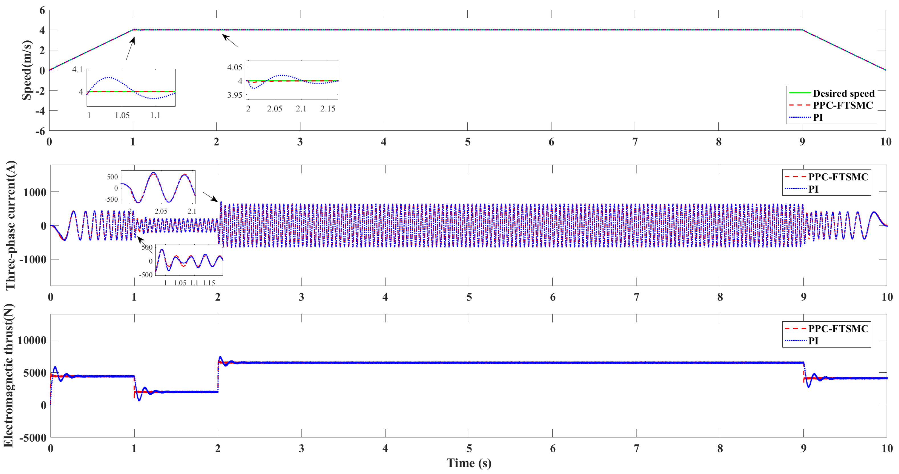
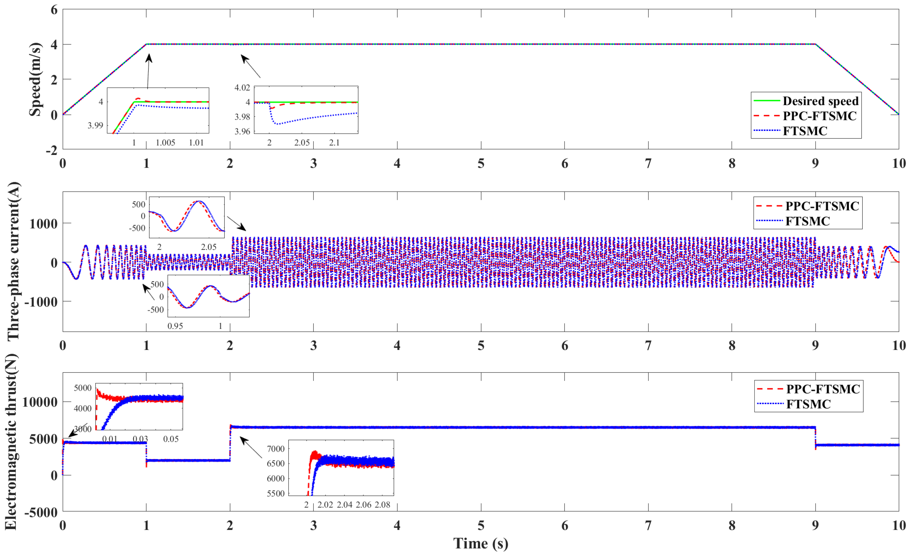
The speed response, three-phase current, and electromagnetic thrust presented in Figure 2 and Figure 3. As we can see, the three-phase current waveform of the three methods are relatively stable, but the current waveform of PI will jitter when the motor changes from accelerated operation to uniform operation at 1 s. And at 2 s, when the lumped disturbance changes, the current waveform of PI will peak. But the current waveform of FTSMC and PPC-FTSMC can remain stable throughout the motor operation. In terms of electromagnetic thrust, the thrust waveform of PI is overblown by a relatively obvious amount of about 20 % in the starting state of the motor. In addition, when the machine acceleration changes and the lumped disturbance changes, the thrust waveform of the motor will be overblown, and the adjustment time is about 0.3 s. When adopt FTSMC, although the motor thrust waveform is not overshooting, the adjustment time is slightly longer than that of PPC-FTSMC. Throughout the entire control process, large electromagnetic thrust pulsation will cause motor jitter. Under the influence of the PPC-FTSMC, the three-phase current and electromagnetic thrust response speed of the motor are faster than those of the other controller, enabling quicker attainment of the steady state value. Furthermore, when the motor encounters abrupt lumped disturbances, the PPC-FTSMC promptly stabilizes the motor’s electromagnetic thrust, diminishes the magnitude of speed variations, and reduces jitter.
Further, the tracking performance of the motor is analyzed by Figure 4, it can be seen that the PI controller fails to effectively track the specified speed signal and the overshoot controlled is undoubtedly the largest in the start stage of the motor. It takes approximately 0.4 s for the system to attain the desired speed and achieve a steady state. Although FTSMC is no overshoot, its response time is the longest, about 2 s, it proves that its speed response performance is the worst. PPC-FTSMC is used for the fastest dynamic response, with a response time of about 0.01 s and the smallest error significantly better than the other two methods. At 2 s, the system lumped disturbance changes, the motor speed tracking error of PPC-SMC can be effectively limited to the set 0.01 m/s, the adjustment time is about 0.02 s, while the maximum tracking error of PI control is 0.02 m/s, and the maximum tracking error of FTSMC control is 0.03 m/s.
Case 2: Set the reference speed curve to a sinusoidal signal, its frequency is 2 rad/s and amplitude is 5 m/s.
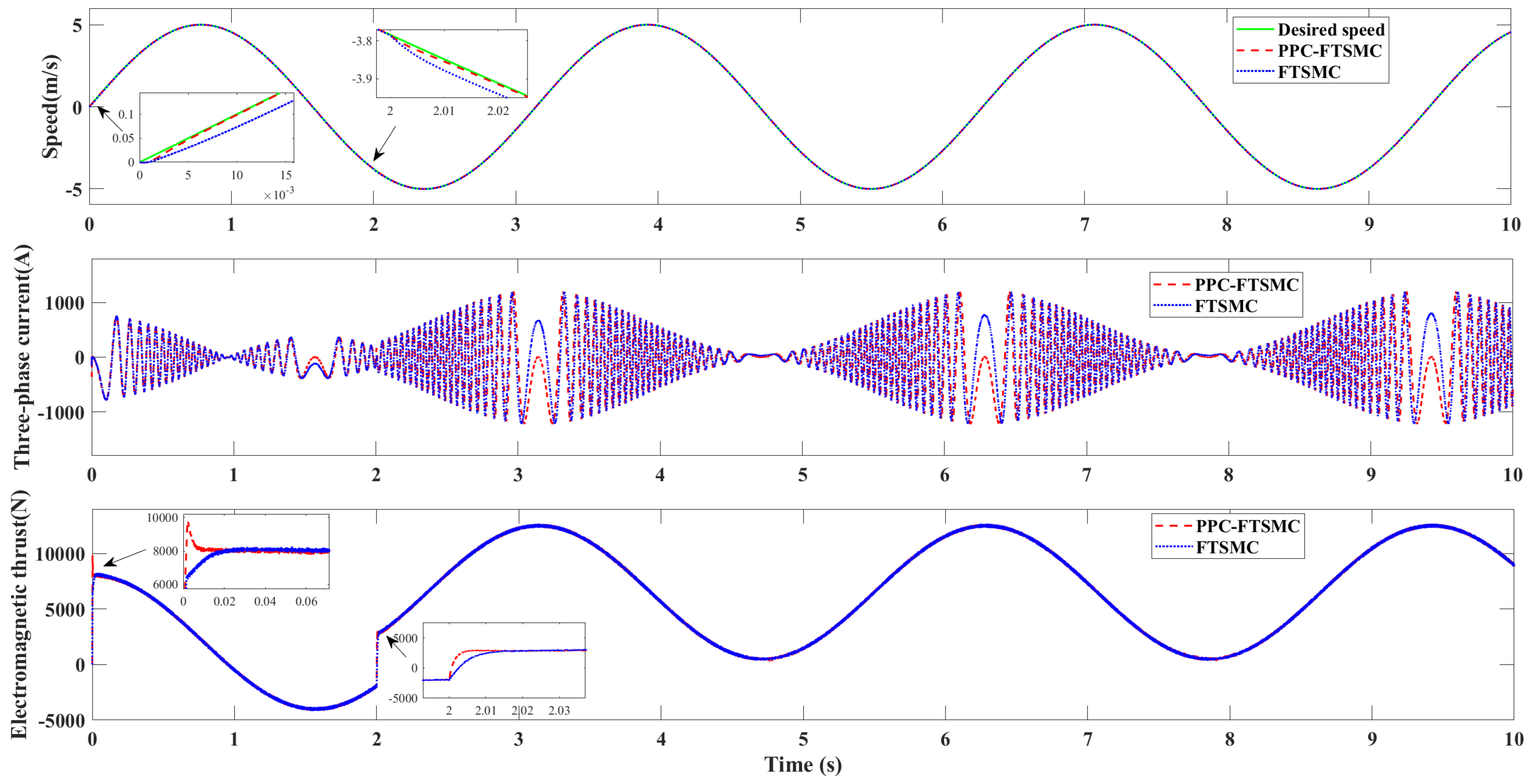
As shown in Figure 5 and Figure 6, in terms of three-phase current, the three-phase current waveform of the three methods is relatively stable, but the three-phase current of PPC-FTSMC is more stable than the other two methods. When the motor is started, the thrust waveform will have a period of continuous 4 s oscillation in PI controller. Although the thrust of FTSMC is not overshot, it also has a response time lasting 0.02 s. The response time of thrust waveform of the motor system using PPC-FTSMC is the shortest, only 0.01 s, compared with other two algorithms. Similarly, when the load is disturbed for 2 s, PPC-FTSMC still has the fastest response time. It can be proved that when the whole system encounters lumped disturbance changes, the motor system using PPC-FTSMC can stabilize the electromagnetic thrust of the motor faster, reduce the amplitude of speed change, and reduce jitter. The speed signal of the motor is further analyzed according to Figure 7, when using PI control, the motor system cannot track the reference signal in time. When the speed signal reaches the amplitude, there will be a large speed tracking error of 0.01 m/s. In the motor system using FTSMC and PPC-FTSMC, the speed tracking error will approach 0, that is, the motor speed will eventually approach the given speed signal. The difference is that the dynamic adjustment performance of the motor system using FTSMC is poor, in the initial operation stage of the motor and when the load disturbance changes, the adjustment time is about 2 s, longer than that of PPC-FTSMC. In the whole operation process of the motor, whether in the initial stage or when the load disturbance changes, the speed tracking error of PPC-FTSMC can be kept within the limited 0.01 m/s.
In order to show the superiority of PPC-FTSMC controller, quantitative analysis of the motor’s speed error data is conducted. The three error indicators listed in this article include maximum error (MAX), average absolute error (AVG), and root-mean-square error (RMS). The specific formula are as follows:
MAXerror = max i ε ( i ) 2
AVGerror = i = 1 N | ε ( i ) | N
RMSerror = i = 1 N ε 2 ( i ) N
The speed error indexes of three control strategies under two simulation conditions are given in Table 2. In terms of the error value, the speed tracking error of the motor system using PPC-FTSMC is much smaller than that of the other two methods. As can be seen from Table 2, the motor error value of PPC-FTSMC is less than 0.01 m/s given in the prescribed performance function. It is proved that the motor system with PPC has excellent performance in speed tracking control.

5. Conclusions

This paper introduces a fixed-time sliding mode controller with prescribed performance strategy, which is used for the control of a permanent magnet linear synchronous motor (PMLSM). Fixed-time sliding mode control is incorporated into the design of the speed control loop for the PMLSM, improving the system control performance, and achieving sliding mode controller stability in a fixed time, and accelerating the motor’s speed error convergence. Furthermore, the prescribed performance function is applied to transform the constrained speed-tracking error into an unconstrained conversion error. Subsequently, a control law is formulated to limit the error within predefined bounds. This ensures that the system’s dynamic characteristics, steady-state error, and other crucial performance indicators satisfy prescribed requirements. The efficacy of the proposed method is validated through simulation experiments. A comparative analysis is conducted against a PI controller and FTSMC, revealing that the proposed approach exhibits satisfactory control performance and induces smaller speed fluctuations. It is worth further considering that external disturbance will inevitably affect the operation of the PMLSM system. Although the prescribed performance control can limit the speed error within predefined bounds, its anti-interference effect is still not ideal. In follow-up work to this paper, a suitable disturbance observer will be design to improve anti-interference capability.

Author Contributions

Conceptualization, G.H. and C.Y.; methodology, G.H. and Q.S.; software, C.Y; validation, W.Y.; formal analysis, G.H.; investigation, C.Y.; data curation, Y.W.; writing—original draft preparation, G.H.; writing—review and editing, G.H.; supervision, W.Y.; project administration, Q.S. All authors have read and agreed to the published version of the manuscript.

Funding

This research received no external funding.

Data Availability Statement

The data and materials used to support the results of this study cannot be obtained due to privacy reasons.

Conflicts of Interest

The authors declare no conflict of interest.

References

  1. Yin, X.; She, J.; Liu, Z.; Wu, M.; Kaynak, O. Chaos suppression in speed control for permanent-magnet-synchronous-motor drive system. J. Frankl. Inst. 2020, 357, 13283–13303. [Google Scholar] [CrossRef]
  2. Cheng, S.; Yu, J.; Zhao, L.; Ma, Y. Adaptive fuzzy control for permanent magnet synchronous motors considering input saturation in electric vehicle stochastic drive systems. J. Frankl. Inst. 2020, 357, 8473–8490. [Google Scholar] [CrossRef]
  3. Zhang, H.; Kou, B.; Jin, Y.; Zhang, H. Investigation of auxiliary poles optimal design on reduction of end effect detent force for PMLSM with typical slot–pole combinations. IEEE Trans. Magn. 2015, 51, 1–4. [Google Scholar]
  4. Wang, M.; Yang, R.; Zhang, C.; Cao, J.; Li, L. Inner loop design for PMLSM drives with thrust ripple compensation and high-performance current control. IEEE Trans. Ind. Electron. 2018, 65, 9905–9915. [Google Scholar] [CrossRef]
  5. Shi, Z.; Wang, Y.; Ji, Z. Bias compensation based partially coupled recursive least squares identification algorithm with forgetting factors for MIMO systems: Application to PMSMs. J. Frankl. Inst. 2016, 353, 3057–3077. [Google Scholar] [CrossRef]
  6. Lin, F.J.; Hwang, J.C.; Chou, P.H.; Hung, Y.C. FPGA-based intelligent-complementary sliding-mode control for PMLSM servo-drive system. IEEE Trans. Power Electron. 2010, 25, 2573–2587. [Google Scholar] [CrossRef]
  7. Cho, K.; Kim, J.; Choi, S.B.; Oh, S. A High-Precision Motion Control Based on a Periodic Adaptive Disturbance Observer in a PMLSM. IEEE/ASME Trans. Mechatron. 2015, 20, 2158–2171. [Google Scholar] [CrossRef]
  8. Kommuri, S.K.; Park, Y.; Lee, S.B. Online Compensation of Mechanical Load Defects With Composite Control in PMSM Drives. IEEE/ASME Trans. Mechatron. 2021, 26, 1392–1400. [Google Scholar] [CrossRef]
  9. Wang, M.; Li, L.; Pan, D.; Tang, Y.; Guo, Q. High-Bandwidth and Strong Robust Current Regulation for PMLSM Drives Considering Thrust Ripple. IEEE Trans. Power Electron. 2016, 31, 6646–6657. [Google Scholar] [CrossRef]
  10. Wang, J.; Li, D. Application of fuzzy PID control in PMLSM servo drive system. In Proceedings of the 2015 IEEE International Conference on Mechatronics and Automation (ICMA), Beijing, China, 2–5 August 2015; IEEE: Piscataway, NJ, USA, 2015; pp. 6–10. [Google Scholar]
  11. Chen, S.Y.; Liu, T.S. Intelligent tracking control of a PMLSM using self-evolving probabilistic fuzzy neural network. IET Electr. Power Appl. 2017, 11, 1043–1054. [Google Scholar] [CrossRef]
  12. Wang, M.S.; Tsai, T.M. Sliding mode and neural network control of sensorless PMSM controlled system for power consumption and performance improvement. Energies 2017, 10, 1780. [Google Scholar] [CrossRef]
  13. Jon, R.; Wang, Z.; Luo, C.; Jong, M. Adaptive robust speed control based on recurrent elman neural network for sensorless PMSM servo drives. Neurocomputing 2017, 227, 131–141. [Google Scholar] [CrossRef]
  14. Lu, E.; Li, W.; Yang, X.; Liu, Y. Anti-disturbance speed control of low-speed high-torque PMSM based on second-order non-singular terminal sliding mode load observer. ISA Trans. 2019, 88, 142–152. [Google Scholar] [CrossRef] [PubMed]
  15. Feng, Y.; Yu, X.; Man, Z. Non-singular terminal sliding mode control of rigid manipulators. Automatica 2002, 38, 2159–2167. [Google Scholar] [CrossRef]
  16. Komurcugil, H. Non-singular terminal sliding-mode control of DC–DC buck converters. Control Eng. Pract. 2013, 21, 321–332. [Google Scholar] [CrossRef]
  17. Moulay, E.; Léchappé, V.; Bernuau, E.; Defoort, M.; Plestan, F. Fixed-time sliding mode control with mismatched disturbances. Automatica 2022, 136, 110009. [Google Scholar] [CrossRef]
  18. Hu, Y.; Yan, H.; Zhang, H.; Wang, M.; Zeng, L. Robust adaptive fixed-time sliding-mode control for uncertain robotic systems with input saturation. IEEE Trans. Cybern. 2022, 53, 2636–2646. [Google Scholar] [CrossRef] [PubMed]
  19. Yu, L.; He, G.; Wang, X.; Zhao, S. Robust fixed-time sliding mode attitude control of tilt trirotor UAV in helicopter mode. IEEE Trans. Ind. Electron. 2021, 69, 10322–10332. [Google Scholar] [CrossRef]
  20. Zamani, H.; Khandani, K.; Majd, V.J. Fixed-time sliding-mode distributed consensus and formation control of disturbed fractional-order multi-agent systems. ISA Trans. 2023, 138, 37–48. [Google Scholar] [CrossRef]
  21. Pan, H.; Zhang, G.; Ouyang, H.; Mei, L. Novel fixed-time nonsingular fast terminal sliding mode control for second-order uncertain systems based on adaptive disturbance observer. IEEE Access 2020, 8, 126615–126627. [Google Scholar] [CrossRef]
  22. Wang, L.; Du, H.; Zhang, W.; Wu, D.; Zhu, W. Implementation of integral fixed-time sliding mode controller for speed regulation of PMSM servo system. Nonlinear Dyn. 2020, 102, 185–196. [Google Scholar] [CrossRef]
  23. Dai, Y.; Ni, S.; Xu, D.; Zhang, L.; Yan, X.G. Disturbance-observer based prescribed-performance fuzzy sliding mode control for PMSM in electric vehicles. Eng. Appl. Artif. Intell. 2021, 104, 104361. [Google Scholar] [CrossRef]
  24. Song, Y.; Xia, Y.; Wang, J.; Li, J.; Wang, C.; Han, Y.; Xiao, K. Barrier Lyapunov function-based adaptive prescribed performance control of the PMSM used in robots with full-state and input constraints. J. Vib. Control 2023, 29, 1400–1416. [Google Scholar] [CrossRef]
  25. Bu, X.; Wu, X.; Huang, J.; Wei, D. Robust estimation-free prescribed performance back-stepping control of air-breathing hypersonic vehicles without affine models. Int. J. Control 2016, 89, 2185–2200. [Google Scholar] [CrossRef]
  26. Qin, H.; Wu, Z.; Sun, Y.; Chen, H. Disturbance-observer-based prescribed performance fault-tolerant trajectory tracking control for ocean bottom flying node. IEEE Access 2019, 7, 49004–49013. [Google Scholar] [CrossRef]
  27. Wang, X.; Wang, X.; Wang, Z.; Xiao, X.; Li, S. Composite finite-time control for PMSM with prescribed performance using disturbance compensation technique. Control Eng. Pract. 2023, 141, 105677. [Google Scholar] [CrossRef]
  28. Ding, B.; Xu, D.; Jiang, B.; Shi, P.; Yang, W. Disturbance-observer-based terminal sliding mode control for linear traction system with prescribed performance. IEEE Trans. Transp. Electrif. 2020, 7, 649–658. [Google Scholar] [CrossRef]
  29. Bechlioulis, C.P.; Rovithakis, G.A. Robust adaptive control of feedback linearizable MIMO nonlinear systems with prescribed performance. IEEE Trans. Autom. Control 2008, 53, 2090–2099. [Google Scholar] [CrossRef]
Figure 1. Block diagram of PMLSM control system using PPC-FTSMC strategy.
Energies 17 00952 g001
Figure 2. Simulation performance of speed response, three-phase current, and electromagnetic thrust compared with PI in case 1.
Energies 17 00952 g002
Figure 3. Simulation performance of speed response, three-phase current, and electromagnetic thrust compared with FTSMC in case 1.
Energies 17 00952 g003
Figure 4. Speed tracking error in case 1.
Energies 17 00952 g004
Figure 5. Simulation performance of speed response, three-phase current, and electromagnetic thrust compared with PI in case 2.
Energies 17 00952 g005
Figure 6. Simulation performance of speed response, three-phase current, and electromagnetic thrust compared with FTSMC in case 2.
Energies 17 00952 g006
Figure 7. Speed tracking error in case 2.
Energies 17 00952 g007
Table 1. Parameters of the PMLSM in simulations.
ParametersVariable NameValue
Stator resistance [ Ω ] R s 0.045
Stator Inductance [mH] L s 1.15
Mover mass [kg]M600
Friction coefficient [N·s/m] B v 0.5
pole-pitch [mm] τ 200
permanent magnet flux linkage [Wb] f l u x 0.145
number of pole pairsn2
Table 2. The speed errors comparisons using different methods.
ErrorCase 1Case 2
PPC-FTSMCFTSMCPIPPC-FTSMCFTSMCPI
Maximum Error (m/s) 5.1 × 10 3 3.1 × 10 2 6.7 × 10 2 9 × 10 3 3.05 × 10 2 1.59 × 10 1
Average Absolute Error (m/s) 2 × 10 4 8.3 × 10 3 5.5 × 10 3 2 × 10 4 8.3 × 10 3 1.83 × 10 2
Root Mean Squared Error (m/s) 4 × 10 4 1.07 × 10 2 1.38 × 10 2 5 × 10 4 1.07 × 10 2 3.4 × 10 2
Disclaimer/Publisher’s Note: The statements, opinions and data contained in all publications are solely those of the individual author(s) and contributor(s) and not of MDPI and/or the editor(s). MDPI and/or the editor(s) disclaim responsibility for any injury to people or property resulting from any ideas, methods, instructions or products referred to in the content.