Article

Assessing High-Voltage Shore Connection Safety: An In-Depth Study of Grounding Practices in Shore Power Systems

1
Department of Electrical Engineering, Feng Chia University, Taichung 407102, Taiwan
2
Department of Marine Engineering, National Kaohsiung University of Science and Technology, Kaohsiung 80543, Taiwan
*
Author to whom correspondence should be addressed.
Energies 2024, 17(6), 1373; https://doi.org/10.3390/en17061373
Submission received: 10 January 2024 / Revised: 6 March 2024 / Accepted: 11 March 2024 / Published: 13 March 2024
(This article belongs to the Section F: Electrical Engineering)

Abstract

:
There is growing concern regarding air pollutants (NOx, SOx, and PM) and carbon emissions from ocean-going vessels in harbor areas and the role of high-voltage shore connection (HVSC) systems in mitigating these emissions during vessel berthing. The HVSC operates as a TN grounding system in humid environments, and it needs a proper grounding design to ensure safety when faults occur. This article intends to examine the overvoltage resulting from fault currents and its implications for the safety of operators when a single line-to-ground fault takes place within the design of HVSC grounding systems. The assessment is carried out by employing actual scenarios and parameters from a container berth at Kaohsiung Harbor in Taiwan. Considering site conditions, such as the wet ground surface, human body resistance, and electric shock duration, the tolerable safe voltage level is derived using IEEE Std. 80 and IEC 60479-1. Based on the shore power system grounding architecture specified in IEEE/IEC 80005-1, an equivalent circuit model is constructed to calculate the fault currents using symmetrical component analysis. The actual touch voltages generated in various locations are analyzed under scenarios of connecting or disconnecting the equipotential bonding between the ship and the shore using neutral grounding resistor (NGR) designs. This article delves into the scenarios of electric shock that may occur during the operation of an actual container ship’s shore power system. It evaluates whether various contact voltage values exceed current international standards and verifies the grounding design and safety voltage specifications of IEEE/IEC 80005-1. According to the results of this study, the use of NGR and protective earthed neutral (PEN) conductors in HVSC is crucial. This can limit fault currents, reduce touch voltage, and ensure the safety of personnel and equipment. Therefore, ensuring and monitoring equipment conductors and adopting NGRs of appropriate sizes are crucial elements in maintaining electrical safety in HVSC systems.

1. Introduction

The surge in globalization and international trade has resulted in notable rises in both the quantity of maritime vessels and the expansion of port facilities. In the year 2022, around 80% of the global trade volume took place via maritime routes, with sea transport accounting for over 70% of the total global merchandise value [1]. The volume of goods loaded in ports worldwide tripled from 1990 to 2020, indicating a significant increase in seaborne trade [2]. The COVID-19 pandemic further underscored the importance of transportation, as trade and production faced challenges due to restricted movement of passengers and freight [3]. However, this growth in shipping activity has also resulted in a rise in pollution emissions. In 2020, the global shipping emissions of sulfur oxides (SOx) alone accounted for approximately 16% of the total global emissions [4]. These pollutants, including SOx, nitrogen oxides (NOx), and particulate matter (PM), are emitted by ships during navigation and berthing, posing threats to oceans, ports, and human health. When ships are docked, diesel generators (DGs) must continuously run to provide electricity for the entire vessel, which is also a significant source of air pollution [2]. Notably, 70% of these emissions occur in coastal and adjacent port areas [5]. To address this issue, the International Maritime Organization (IMO) established emission standards for ship generators in Annex VI of the International Convention for the Prevention of Pollution from Ships (MARPOL) [6]. Global port authorities are actively working to control air pollution by adopting various measures, such as using low-sulfur fuel, limiting ship speed, and implementing shore power systems to achieve cleaner air quality in ports.
Shore power systems, also known as cold ironing (CI), alternative maritime power supply (AMP), high-voltage shore connection (HVSC) systems, or onshore power supply (OPS), allow ships to reduce pollution emissions while berthing by utilizing shore power instead of onboard DGs [7]. The first onshore power system was installed at the Gothenburg Port in Sweden in 2000, and the Port of Juneau in the United States pioneered using AMP for cruise ships [7,8]. California took the lead in regulating high-voltage shore power in ports globally and released “California’s Shore Power Requirements” in 2014, with the aim of increasing the proportion of ships using shore power to 80% by 2020 [9]. Additionally, by the end of 2025, all European ports will be required to provide shore power services [10]. As of June 2020, 45 major ports worldwide in the Americas, Europe, and Asia have been equipped with the capability to utilize shore power [11]. HVSC is an important technology that can support the sustainable development of shipping, and it has been proven to effectively reduce pollution emissions from ships [10,11].
On the other hand, the use of shore power can indeed effectively improve air pollution in ports and contribute to achieving the goals of the international climate change treaty of the Paris Agreement by 2050 [2]. Although shore power effectively decreases air pollution and carbon emissions from ships in ports, it does not completely eliminate carbon emissions, as they are still produced during the generation process in power plants. Consequently, current efforts are concentrating on integrating cold ironing systems with diverse renewable energy solutions to attain authentic decarbonization or achieve net-zero emissions when ships are docked [12,13,14,15,16]. Nevertheless, the integration of HVSC encounters hurdles because of the substantial expenses associated with the necessary equipment in ports and aboard vessels. The balance between costs and oil prices, coupled with worries over power consistency, functionality, and security, has resulted in a restrained setup of shore power infrastructure [17]. Factors to consider include dependable power supplies, voltage and frequency standards, connection methods, and electrical safety risks [18]. The shore power system, which bridges the energy needs between the dock and the ship, is intricate. It demands a meticulous design and standards to ensure safety and reliable power delivery. This system encompasses onshore substations, connection sockets, transmission cables, and the ship’s power-distribution panels. As stipulated by the IEEE/IEC 80005-1 standard [19], conducting thorough analyses and calculations is imperative. This includes considerations for the transformer’s grounding design, resistance values in neutral line grounding, and evaluations of fault and charging currents for both the ship and shore sides. Additionally, the incorporation of suitable protective equipment is crucial.
The HVSC links the shore-side power substation and ships, providing electricity to vessels docked in the port and effectively reducing port pollution by shutting down onboard diesel generators. Power supply stability and operational safety are major consideration factors for adopting HVSC. The most common faults occurring during supply are single-phase ground faults and three-phase short-circuit faults. Fault currents can cause hazards to personnel and damage to equipment. Therefore, only proper grounding design and protective equipment can reduce fault currents and isolate the faulted area, enhancing system protection margins [20,21]. When a phase conductor experiences a three-phase short-circuit fault, it can jeopardize its regular operation. Through the calculation of short-circuit fault currents, the capacity of circuit breaker protective equipment can be determined. IEC 60909-0 [22] and IEC 61363-1 [23] are currently the most commonly used standards for calculating fault currents. Among them is IEC 61363-1, which, although applicable to calculating fault currents for ships, does not explicitly specify its use for shore power systems [24]. During HVSC operation, operators plug in the power cable to the shore- and ship-side sockets to supply power to the ship. It is possible for single-phase-to-ground (line to earth) faults to occur in HVSC systems, which poses a risk of high voltage to personnel near the fault point [25]. The IEEE80005-1 standard and rated literature have discussed that, during faults, electric shock incidents occurring anywhere in the system due to direct or transferred voltages must be avoided. In addition, the touch or step voltage should be limited to not exceed 30 V. Furthermore, the limitation on single-phase ground fault currents must be further discussed regarding galvanic corrosion issues to ensure the integrity of the ship’s structure [26,27,28,29,30].
The HVSC features multiple (double) grounding systems, making it crucial to assess the touch voltage during the design and operation of the grounding system in high-voltage marine power systems [31]. Therefore, it is essential to focus on the safety equipment and proper operation of the HVSC when designing and discussing grounding systems for the shore and ship [32,33]. According to the IEC/IEEE 80005-1 standard, the neutral point of the shore-side transformer in HVSC systems must be connected to an earthing resistor to establish equipotential bonding between the ship and shore. However, the literature does not further discuss and analyze this. The neutral grounding system method is defined as the TN earthing system in the IEC 60364 [34] standard while installing a high-resistance grounding (HRG) or low-resistance grounding (LRG) at the transformer neutral point to limit the fault current [25,26]. The setting of the neutral grounding resistor (NGR) can help to reduce fault currents and ensure safety. Previous literature has discussed the selection of appropriate grounding resistance [24,35,36,37].
Shore power systems operate in a medium–high-voltage humid environment of 11.4–6.6 kV. When a single-phase ground fault occurs, the overvoltage produced by the current passing through the human body is critical in assessing system safety. It can also affect the willingness to use and promote shore power. The above-related issues are rarely fully discussed and verified with examples in international standards and literature. This paper will discuss the impact on safety voltage in shore power systems, particularly regarding the use of HRG or LRG at the shore-side transformer’s neutral point and the correct connection of equipotential bonding through relevant international standards, circuit impedance theory, and practical case scenarios. Taking Kaohsiung Port’s shore power berth as an example, an equivalent circuit model is constructed. Based on the permissible safe voltage criteria of IEEE Std. 80 and adding in scenario factors like a humid environment, human body resistance, and electric shock duration, the direct and indirect contact electric shock situations at the shore power system junction box and ship side are comprehensively discussed. The following sections of this article are organized as follows: Section 2 introduces the HVSC grounding system requirements, Section 3 discusses the safety assessment, and Section 4 presents a case study of Kaohsiung Harbor. Finally, Section 5 provides the conclusions and recommendations of this article.

2. HVSC Grounding System Requirements

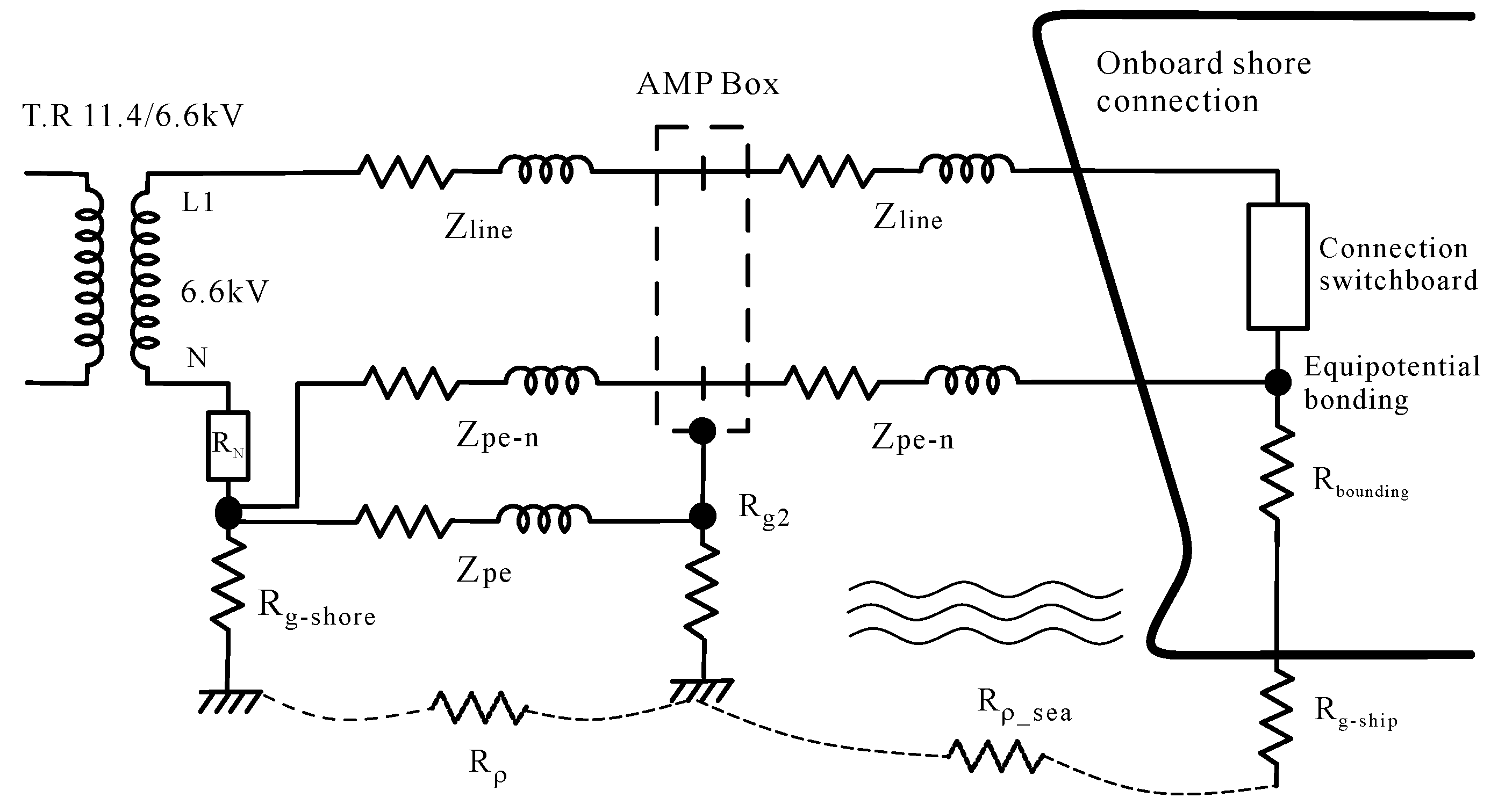
2.1. HVSC System Framework

The shore power system comprises multiple subsystems, including the power supply, ship-shore connection, and ship-side power-receiving systems. The HVSC consists of three main components: a shore-side substation that reduces the voltage to 11.4 or 6.6 kV, a ship-side power-receiving panel that receives the power through a connection box, and a cable management system that handles the cables. Figure 1 illustrates the HVSC systems defined by the IEC/IEEE 80005-1 standard [19]. The IEC/IEEE 80005-1 standard provides guidelines for the connection, transmission, transformation, distribution, control, and monitoring of HVSC systems. Although it regulates the power supply system, equipment, and sockets, the technology and specifications can be complex. HVSC can be divided into two parts: the shore and the ship. The shore-side power system and equipment must comply with the port’s national standards and electricity provider’s regulations. Currently, the HVSC systems of international commercial ports worldwide are typically constructed following the framework of the IEC/IEEE 80005-1 standard. Additionally, container ships are the most common type of vessel equipped with HVSC systems, operating at a receiving voltage of 6.6 kV.

2.2. HVSC Grounding (Earthing) System

Shore power systems present electrical hazards due to the effects of seawater salinity and humidity on equipment insulation and human body impedance, as damp conditions can decrease resistance and increase the risks of electric shocks. To mitigate these risks, international standards impose limits on safe voltage levels at various points in shore power systems and provide regulations regarding proper equipment protective measures and grounding designs for these electrically unfriendly environments. As previously discussed, the design of grounding for shore power systems is closely related to safe operating voltages. In many technical documents and works in the literature, “grounding” and “earthing” refer to the same concept. International standards for grounding systems can be found primarily in the IEC 60364 series of standards. These standards provide three primary earthing system arrangements: TN (transformer neutral earthed, frame connected to neutral), TT (transformer neutral earthed and frame earthed separately), and IT (unearthed transformer neutral, earthed frame). Each system has its advantages, disadvantages, and suitable applications. The TN earthing system continuously provides a return path for faults in the electrical network. The earthing conductors at the transformer and equipment are interconnected via the protective conductor (PE). This loop returns fault currents to the transformer neutral point instead of through the human body, ensuring operator safety. This earthing arrangement provides good personnel safety, but weaker equipment protection. It is an economical and moderately safe earthing design.
IEEE/IEC 80005-1 focuses on regulating the neutral earthing resistor of the shore-side transformer and the equipment-earthing conductor bonding between the ship side and shore side. It adopts the TN-C (Combined PE and neutral line) grounding system per IEC 60364. Section 6.2.4 of the IEC/IEEE 80005-1 standard mandates the establishment of equipotential bonding between the grounding bus of the shore-side transformer and the equipment-earthing of socket outlets, ship hull, and ship-side switchgear earthing bus. Protective earthed neutral (PEN) conductors create an equipotential bond between the shore and the ship. The ship itself has a common equipotential bus connected to the hull. The equipotential bonding between the ship’s hull and the shore grounding system avoids any possible potential difference between the dock and hull, making the HVSC process safe both for port personnel and the ship’s guests. Continuous monitoring is necessary to promptly detect line faults, ensuring the safety of personnel and equipment. According to Section 6.2.3 of the IEC/IEEE 80005-1 standard, the maximum allowable safety voltage for touch and step voltage resulting from any ground fault in the OPS is 30 V. Figure 2 and Figure 3 present the HVSC grounding architecture and single-phase equivalent circuit diagram, respectively. Figure 2 distinguishes between the transformer, switchgear, AMP box (socket outlets), and ship-side onboard switchgear. The neutral point of the shore-side transformer is connected to the PEN and PE conductors on both the ship side and shore side through the neutral earthing resistor RN.
Two types of NGRs (RN) are commonly used: HRG and LRG. The HRG method effectively suppresses the fault current on the line, preventing overvoltage and ensuring the safety of personnel and equipment. The HRG method requires ensuring that the fault current is equal to or slightly higher than the system charging current [24,35,36]. In Section 6.2.3 of IEEE 80005-1, the fault current generated by the impedance should be at least 1.25 times the system charging current, with a value exceeding 25 A–5 s. However, the same shore power system paired with different ship types and electrical architectures can result in varying system charging currents [32]. However, it is essential to consider the system charging current during the size design of the HRG. For 6.6 kV system transformers at container terminals, the recommended maximum NGR value is 200 Ω. Table 1 provides the recommended shore power system operating voltages, power demands, and NGR settings for various ship types in IEEE/IEC 80005-1.
Conversely, the LRG method guarantees that the current of unidirectional grounded faults exceeds the 25 A threshold specified in the IEEE 80005-1 regulations. Appropriate protective devices must still be implemented alongside this method to ensure safety. Notably, this design approach requires less consideration of the system’s charging current. To ensure proper fault clearance, the neutral point of the shore-side transformer must be grounded through an NGR. This NGR must be continuously monitored to ensure circuit breaker tripping during faults. Low-resistance grounding resistors are typically rated 400 amps for 10 s and are commonly found in medium- and high-voltage systems. However, the design values adopted for Kaohsiung Port (Taiwan) are 10 Ω and 400 A–10 s.

3. Safety Voltage Assessment in HVSC

3.1. Body Resistance and Permissible Current

In a grounding fault, individuals near the fault point or in direct contact with equipment or conductors carrying a current face the potential risk of fatal ventricular fibrillation. This danger arises from the voltage generated by the current flowing through their body or between their feet. The likelihood of this situation occurring depends on factors such as the current magnitude, frequency, duration, and the path the current takes through the human body. In HVSC systems, grounding faults can result in electric shock hazards within substations, socket outlet boxes, or receiving panels on ships. It is imperative to prioritize safety measures and implement robust grounding systems to mitigate these risks and protect personnel involved in their operation and maintenance. Two major international standards for evaluating safe voltages are IEC 60479-1 [38] and IEEE Std. 80 [39]. The former describes human body impedance concerning frequency, voltage, and the environment. The latter regulates substation grounding for safety and design. Both use different approaches for determining human body impedance and calculating safe voltages.
IEEE Std. 80 uses a human body resistance RB (hand-to-feet, hand-to-hand, and one foot to the other, excluding external resistances like the skin and shoes) of 1000 Ω, based on Dalziel’s experiments on let-go currents [40]. The RB of 1000 Ω approximately represents the hand-to-feet resistance. For safe voltages, animal electric shock experiments have determined the 0.5% percentile rank of maximum non-fibrillating current and 0.5% percentile rank of minimum fibrillating current as the safe current thresholds [41]. Mapping 50 kg and 70 kg human bodies against the 0.5% percentile minimum fibrillating current curve yields allowable safe currents IB of 67 mA and 91 mA, respectively. Back-calculating the empirical withstand constant SB and energy constant k gives 0.116 and 0.157, respectively. Finally, the general formula for allowable safe current for any shock duration ts is given by Equation (1).
I B = k t s
IEC 60479-1 provides variations in human body resistance RB due to parameters such as skin, voltage, frequency, and temperature. The human electric shock experiments involved three stages with different AC voltages in dry and wet conditions. The 5%, 50%, and 95% percentile ranks of RB variations across the sample population were statistically determined. IEC 60479-1 defines RB more comprehensively than IEEE Std. 80, but does not provide calculation methods for allowable safety voltages. Thus, C.H. Lee and Sakis Meliopoulous, A.P. [42] proposed voltage calculations using IEEE Std. 80 alongside the body current–shock duration ventricular fibrillation probability curves of IEC60479-1. The 50 kg and 70 kg safety current curves from IEEE Std. 80 were inserted. For a chosen shock duration (ts), the permissible body current was calculated, and IEEE Std. 80 was then used to determine the safety voltage. Additionally, according to IEC60479-1’s body voltage–impedance diagram across dry and wet conditions, body resistance converged to approximately 1000 Ω above a 700 V contact voltage. Hence, a body resistance of 1000 Ω (excluding shoes) and the permissible current criteria from IEEE Std. 80 were used in subsequent derivations of allowable safe voltages.

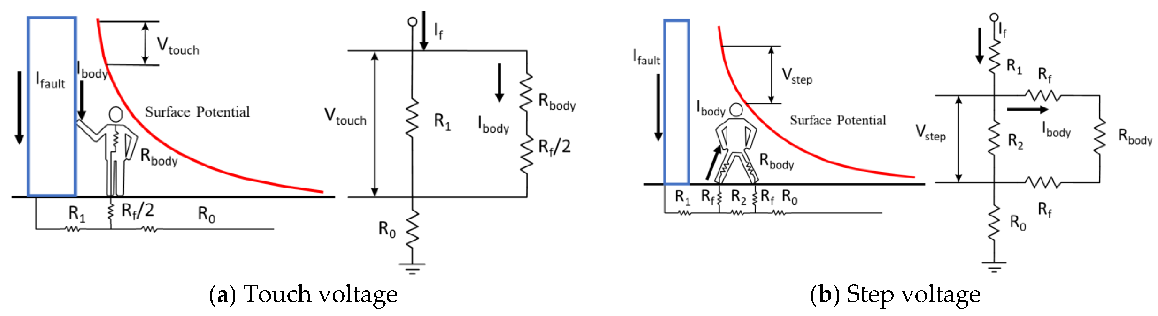
3.2. Shock Model and Permissible Voltage

When discussing the permissible safety voltage, defining the electric shock model is essential. This model considers the voltage generated by the fault current flowing through the human body between the body and the earth. Figure 4 shows the model and its equivalent circuit, where Figure 4a represents the touch voltage, which is the potential difference generated when the human body comes into contact with an energized object. The fault current flows through the body to the earth. Figure 4b represents the step voltage, which is the voltage potential between the two feet. In Figure 4, the metal object is represented by blue, while the red curve illustrates the associated surface potential difference. In this model, R b o d y represents the human body resistance, I b o d y is the current flowing through the human body, R 1 represents the grounding resistance between the charged frame and the foot, R 2 represents the grounding resistance between the two feet, R 0 is the grounding-point resistance from the foot to infinity, and R f   represents the grounding resistance between the foot and the ground.
In HVSC systems, if the grounding or protection design is inadequate, it can result in casualties. Two important voltage-assessment parameters are the permissible and actual voltage. The actual voltage must be lower than the permissible voltage, and the formula can be obtained from Ohm’s theorem.
E = I b o d y ( R b o d y + R s h o e s + R T H )
In Equation (2), I b o d y represents the permissible current of the human body (amperes), R b o d y is the human body resistance of 1000 Ω, R s h o e s is the shoe resistance, and R T H describes other equivalent resistances in the circuit. In the safety criteria of IEEE Std. 80, the permissible current of a 70 kg body is 0.157 / t s , where t s is the shock time (seconds). When considering the situation of wearing shoes, the permissible touch and step voltage are as shown in Equations (3) and (4), where ρ s is the surface resistivity of the earth (Ω-m) and C s is the surface layer derating factor (default to 1).
E t o u c h = 0.157 ( 1000 + R s h o e s 2 + 1.5 C s ρ s ) / t s
E s t e p = 0.157 ( 1000 + 2 R s h o e s + 6 C s ρ s ) / t s

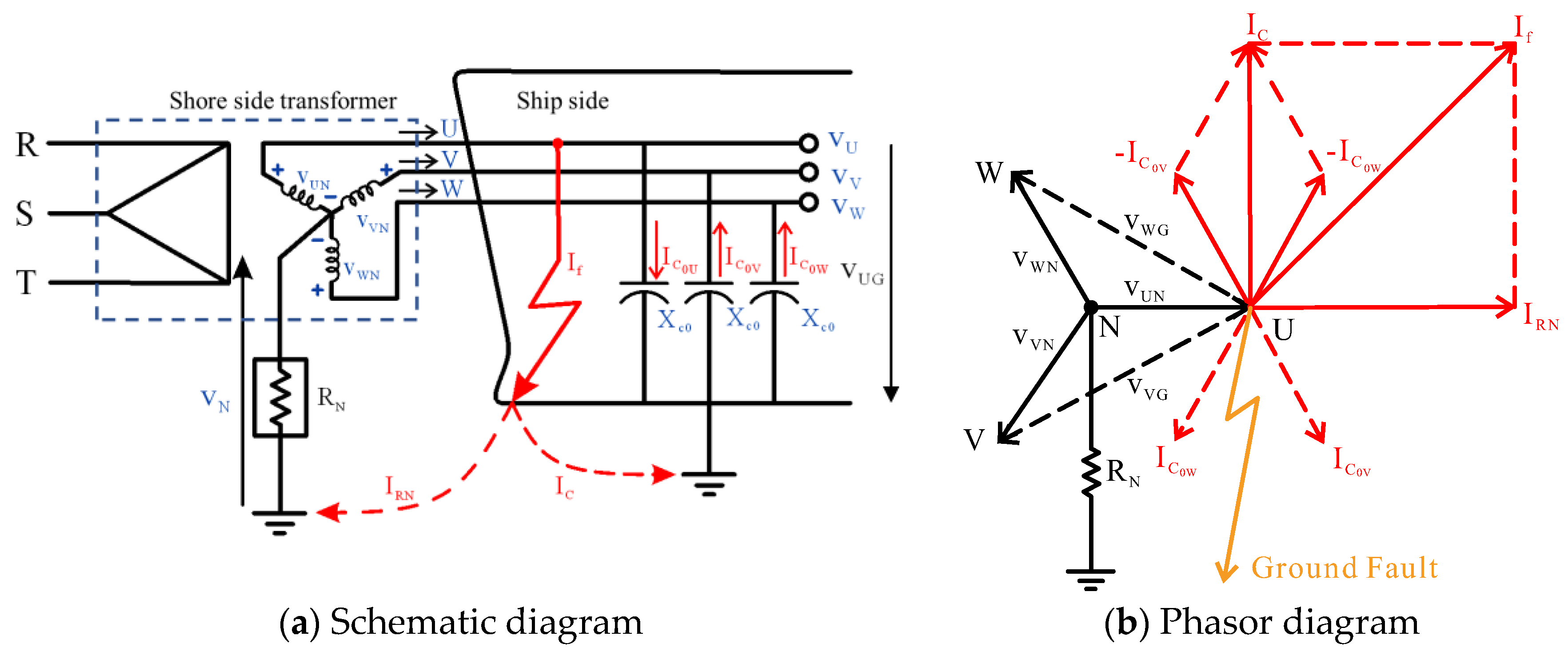
3.3. Phase to Ground Fault Current

Several types of faults are prevalent and hazardous in power systems, and single-phase ground faults are the most common in HVSC systems. When determining the thresholds of touch and step voltage produced within the human body during an electric shock event, it is essential to first calculate the fault current during the fault condition, which can be calculated using either the system charging current or the symmetrical component method.
  • System-Charging-Current Method [35,36]
Figure 5 shows the fault current flow and phasor diagram of a U-phase-to-ground fault case of the NGR power system in HVSC. The dashed box represents the typical three-phase transformer configuration used in current shore power systems, following the IEC 60364 TN configuration. The symbol ∆/Y indicates the winding structure on the transformer’s primary (left) and secondary sides (right). In the three-phase distribution system of HVSC, when the power system is energized, the power cables are coupled to the ground through the grounding capacitor C0 (farads). The three-phase grounding capacitances are equal. Hence, the reactance ( X c 0 ) is also the same, as indicated by Equations (5)–(7). The capacitor current IC0 will exist whether or not there is a load. When the normal condition is in the system, this current will remain unchanged and be the same for each phase, with the vector algebraic sum being zero. However, if a ground fault occurs in the U-phase as shown in Figure 5a, the fault current will flow from the U-phase to the ground. Two components will be generated in this system: IRN returning to the transformer neutral point through NGR and the system-charging current IC. Figure 5b shows each phase voltage and current vector diagram when a fault occurs. When considering the system-charging-current method, the grounding capacitor charging current can be obtained through Figure 5b according to Equations (8)–(12), and the fault current is the sum of IRN and IC, as shown in Equation (13), where I C 0 U ,   I C 0 V , a n d   I C 0 W are the charging currents in amperes of phases U, V, and W, respectively, Xc0 is the phase-to-ground capacitive reactance of each phase in ohms, ω is the circular frequency in 60 Hz, V U N is the voltage of phase U in volts, and R N is the neutral ground resistor in ohms.
C 0 = C 0 U = C 0 V = C 0 W
X c 0 = X c 0 U = X c 0 V = X c 0 W
X c 0 = 1 j ω C 0
I C 0 U = V U N X C 0 = j C 0 ω V U N = I C 0 U 90 °
I C 0 V = j C 0 ω V V G = j C 0 ω 3 V U N
I C 0 W = j C 0 ω V W G = j C 0 ω 3 V U N
I C 0 U + I C 0 V + I C 0 W = 0
I C = I C 0 W + I C 0 V = 3 j C 0 ω V U N = 3 I C 0 U
I f a u l t = I R N 2 + I C 2 = ( V U N R N ) 2 + ( 3 j C 0 ω V U N ) 2
According to IEC/IEEE 80005-1, the size of the NGR ( R N ) in the HVSC systems should be determined based on the design standard. The standard limits the current IRN flowing through the neutral resistance under fault conditions to at least 1.25 times the total system charging current IC, as in Equation (14). Therefore, knowing the inherent system-charging current IC is necessary to size the NGR in HVSC correctly. The parameter C0 in Equation (13) can be calculated based on the power cable specifications by the supplier to determine the charging current.
R N = V U N I R N V U N 1.25 I C  
  • Symmetrical Components Method
We assessed personnel safety by simulating the touch and step voltage. When calculating the fault current during a phase-to-ground fault in an unbalanced three-phase HVSC system, it is essential to consider the zero-sequence impedance. Figure 6 illustrates the impedance and phase sequence network of a Y-connected three-phase HVSC system under no-load conditions with a U-phase-to-ground fault. As shown in Figure 6a, during a fault, the U-phase current flows through the grounding resistor Zf and NGR Zn back to the neutral point of the transformer, while the currents in the other two phases are zero (IV = IW = 0). From the sequence network shown in Figure 6b, the symmetrical component method can decompose IU into positive-, negative-, and zero-sequences. They are three equal current components I U 1 , I U 2 , and I U 0 , as shown in Equations (15) and (16). From the equivalent sequence network in Figure 6 and Kirchhoff’s voltage law, we can observe that the three sequence components of VU are the positive sequence voltage subtracted by the product of the impedance sequence and current sequence matrices, as shown in Equation (17). Further rearranging based on the relationship in Equation (18), we obtain Equation (19). Since the ground fault current for the U phase is IU, the fault current (Ifault) can be calculated using the relationship in Equations (16) and (19), as expressed in Equation (20). In the scenario of a direct ground fault depicted in Figure 6a, with Zf being 0, and considering Z s + 3 Z n , Z 0 = Z 1 = Z 2 = Z s due to Z s Z n . This results in Equation (20) being transformed into Equation (21). Here, VU represents the line voltage of the U phase and Z1, Z2, and Z0 represent the positive, negative, and zero-sequence impedances. ZS represents the source impedance and Zn represents the neutral grounding resistance.
I U 0 I U 1 I U 2 = 1 3 1 1 1 1 a a 2 1 a 2 a I U 0 0
I U 1 = I U 2 = I U 0 = 1 3 I U
V U 0 V U 1 V U 2 = 0 E U 0 Z 0 0 0 0 Z 1 0 0 0 Z 2 I U 0 I U 1 I U 2
V U = V U 0 + V U 1 + V U 2
V U = E U ( Z 1 + Z 2 + Z 0 ) I U 0
I f a u l t = I U = 3 I U 0 = 3 ( V U / 3 ) Z 1 + Z 2 + Z 0
I f a u l t = V U / 3 Z n
This study compares the system charging current method with the symmetric component method. In Equation (13), the IC is challenging to determine without cable characteristic parameters. Therefore, this study employs the symmetric component method to calculate fault current and assess the safe voltage in HVSC systems.

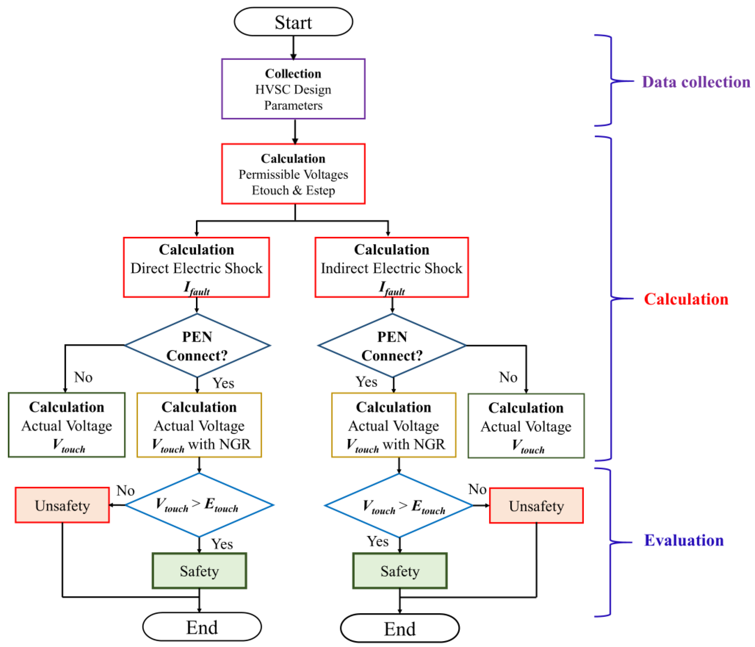
3.4. Assessment Method

This study rigorously examines the safety voltages applicable to the grounding system and operators in the event of direct or indirect faults within HVSC systems. It encompasses a comprehensive analysis of various factors, including the electric shock location, environmental humidity, NGR selection, equipotential conductor conditions, and the duration of the electric shock. The study calculates the electric shock voltage using circuit models evaluated against international safety standards.
Figure 7 is the assessment process of electric shock voltage in this article, which is divided into three principal stages: data collection, calculation, and evaluation. The process begins with gathering pertinent HVSC parameters and conditions, then the computation of the permissible voltage and fault current. Subsequently, the electric shock voltage is calculated based on pre-defined scenarios. In Figure 7, the electric shock types are divided into two scenarios. Direct electric shock is when someone touches a charged conductor. In contrast, indirect electric shock occurs when someone is shocked by touching the metal frame of an electrical device. The final step involves comparing the calculated voltage against the permissible thresholds. A voltage lower than the safe limit is deemed safe according to these criteria.

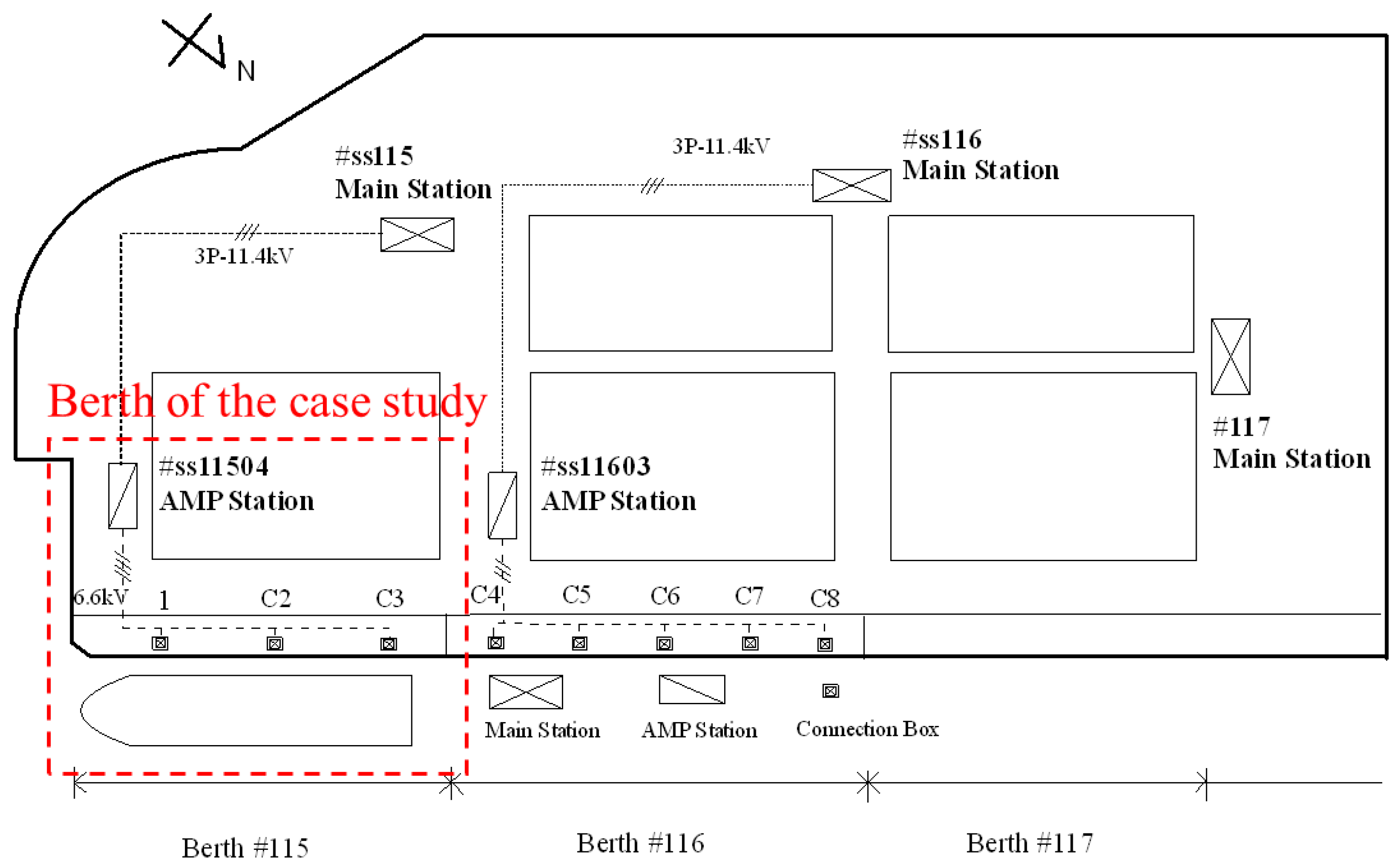
4. Case Study of Kaohsiung Harbor

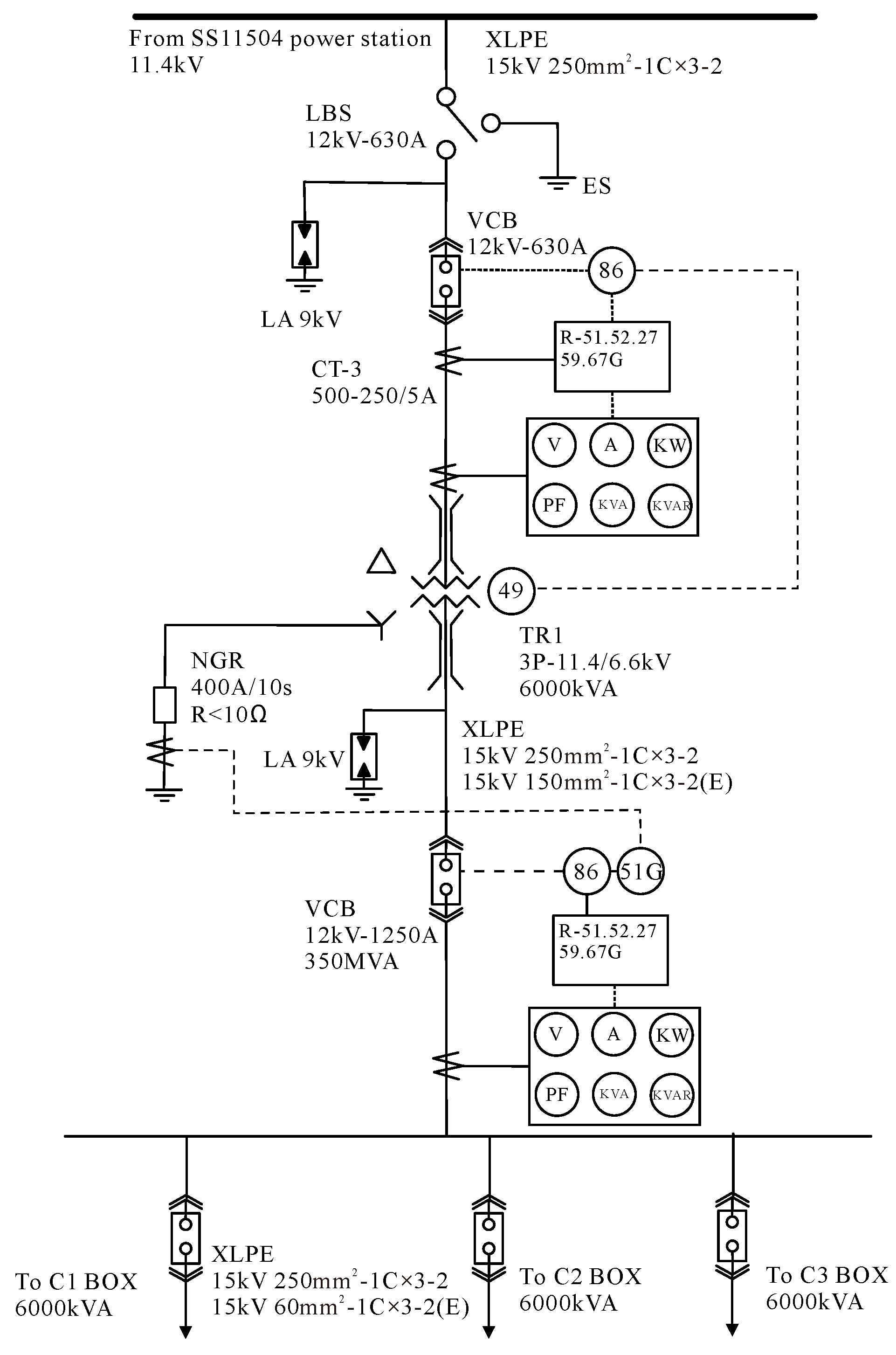
4.1. HVSC Systems of Kaohsiung Harbor

The port of Kaohsiung, the largest seaport in Taiwan and ranked 18th globally for container traffic, utilizes a 6.6 kV medium-voltage HVSC system at berths 115–116. The Kaohsiung Port shore power terminal is constructed according to the IEC/IEEE 80005-1 standard, providing a 6.6 kV power supply system. This system can supply power to container ships of various types and tonnages equipped with shore power-receiving systems. Substations 11504 and 11603 provide three to five sets of shore-side sockets, as depicted in Figure 8. Figure 9 illustrates the single-line diagram of the HVSC system, where the transformer is connected in a Δ-Y configuration. The system follows the TN grounding system specified in the IEC 60364 standard.

4.2. Permissible Touch and Step Voltage

Table 2 shows the permissible touch and step voltages on the shore and ship sides under different weather conditions by using Equations (3) and (4). The NGRs for 5 s and 10 s are 200 Ω (HRG) and 10 Ω (LRG), respectively, which are the fault-clearing times for the protective relay. Due to the risk of electric shock on the ship side (0.5 s and 30 cycles fault-clearing time), the permissible touch voltage is approximately 555 V, which increases to 999 V when wearing gloves. It is much lower than the permissible values for the shore side or junction boxes, indicating a need for greater emphasis on electrical safety measures on board ships. Figure 10 and Figure 11 provide the data from Table 2 in a graphical form. As the duration of the shock time increases, the withstand voltage will decrease significantly. Therefore, detecting and operating the protection device against fault currents is very important. This study sets the relevant resistance parameters based on the reference from IEEE standard 80. The human body resistance, ground surface material resistivities, and duration of electric shock are unlikely to precisely align with the assumed values. From a safety perspective, higher resistance values and shorter contact times generally imply increased safety margins. Hence, this study employs more stringent conditions for calculating and evaluating safety voltage.

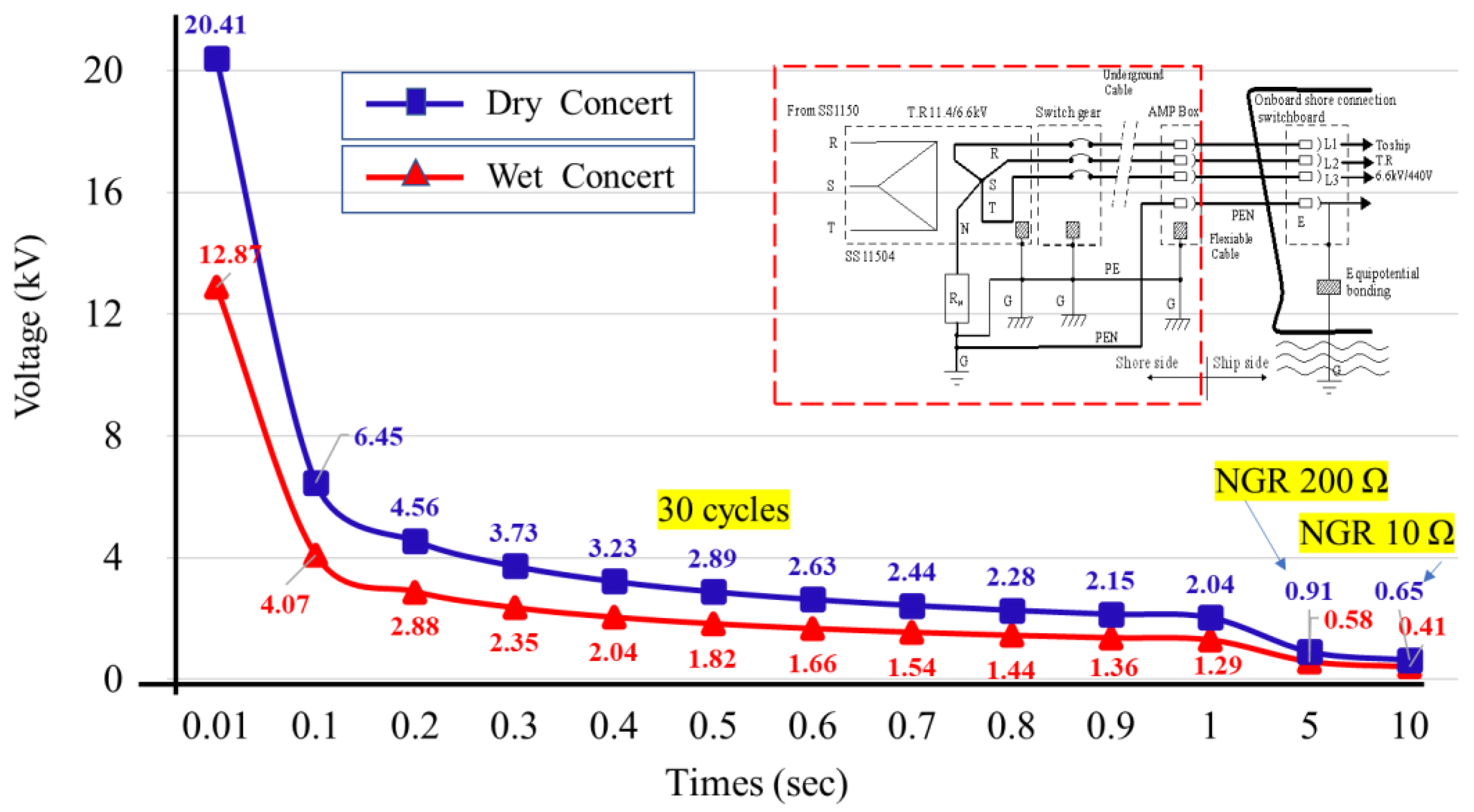
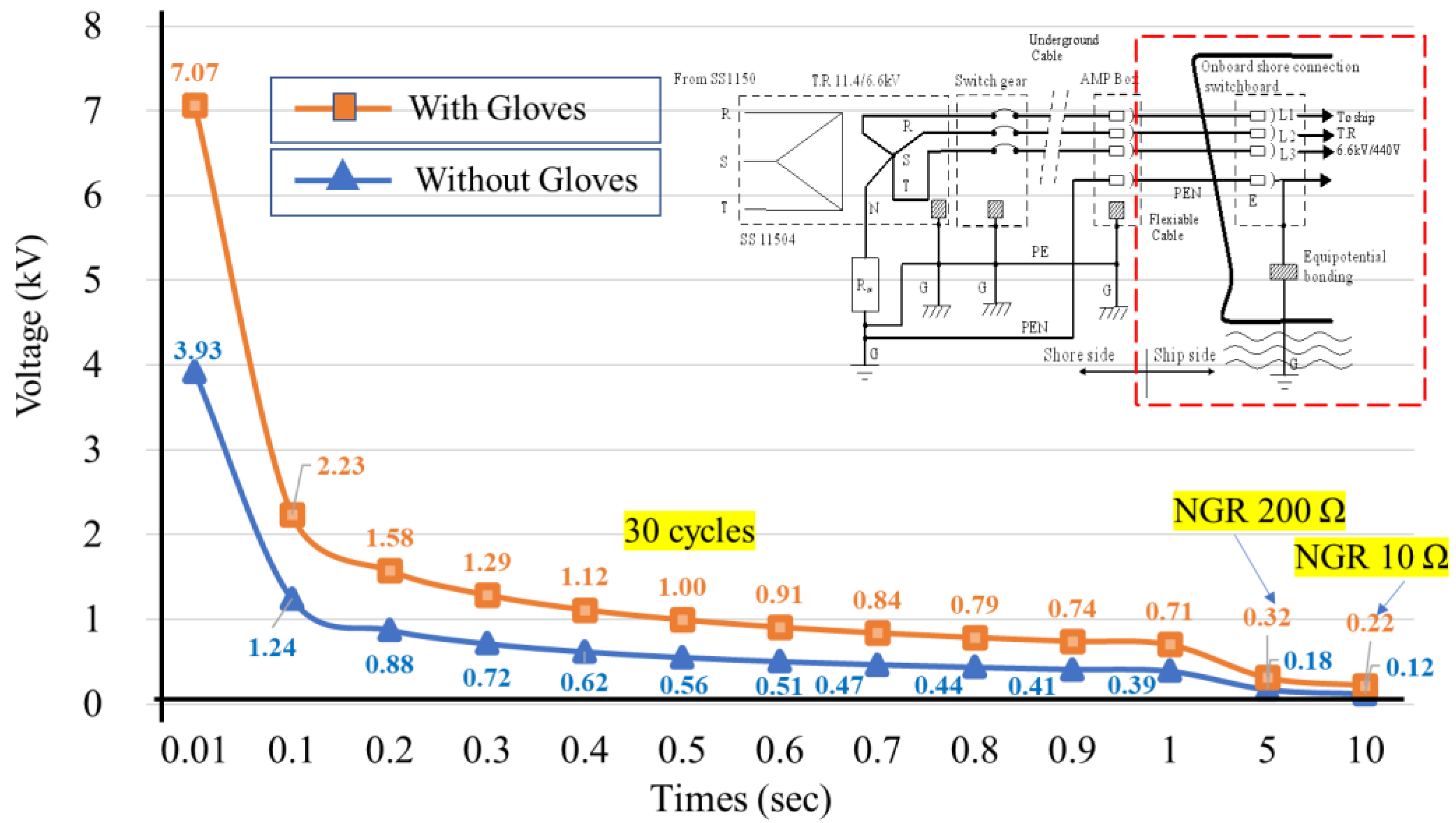
4.3. Actual Touch Voltage in Case Study

Calculating the impedances along the fault current path is essential for determining the actual touch or step voltage during direct and indirect electric shocks when a fault occurs. This study analyzes scenarios where faults occur during operations in the shore-side AMP junction box and the ship-side receiving panel. It also considers situations where NGR and equipotential lines are present. In HVSC systems, the grounding design and safety of onshore substations is superior to that of the ship side, while the danger of touch voltages is higher than that of step voltages. Analyzing touch voltages at onshore junction boxes and the ship side is relatively more necessary in practice. Therefore, analyzing the touch voltages on the ship side is relatively more necessary. This comes in two forms: direct contact when someone touches a charged conductor and indirect contact when someone is shocked by touching the metal frame of an electrical device. Utilizing Ohm’s Law and considering various impedance parameters along the fault path, the fault current during a system fault and the current passing through the human body in different scenarios can be computed. The touch and step voltages across the human body under actual conditions are then calculated using Equations (2)–(4). In case of a direct electric shock, the fault current follows a path through the human body and returns to the neutral point of the transformer at the substation via equipotential conductors. The equipotential conductor loop also contains a parallel circuit (dashed line in Figure 12). This circuit includes a path from the hull, seawater, the earth, and the grounding electrode of the substation, leading back to the neutral point of the transformer. However, the resistance of this circuit is relatively large and can be ignored in the calculation. From Figure 12, Equation (21) can be rewritten as Equation (22) when the fault current flows through the human body, and Z l i n e and Z P E N represent the total impedance of the phase and equipotential conductor cable connecting shore-to-ship, respectively. R m a n refers to the human body resistance, including shoes, and RN represents the resistance of NGR. If the equipotential connection fails, it is as the TT grounding system. In this situation, the impedance path changes and the fault current path goes directly through the hull to the seabed and then returns to the transformer, as shown in Equation (23).
I f a u l t = V U / 3 Z l i n e + Z P E N + R m a n + R N
I f a u l t = V U / 3 Z l i n e + R m a n + R b o n d i n g + R g s h i p
An indirect electric shock occurs when a charged conductor connects a metal frame, transmitting a fault current to the human body through the casing. It is the most common type of electric shock in HVSC, as shown in Figure 13. The fault current returns to the transformer neutral point since the deck is metallic and the frame of the receiving panel is bonded to the equipment earthing bus and equipotential lines. Figure 14 shows an equivalent circuit diagram for an indirect electric shock on the ship side. Equations (24)–(26) calculate the fault current and human body touch voltage based on the circuit diagram. The current I b flowing through the human body is the shunt of the human body resistance and the metal frame resistance to I f a u l t .
I f a u l t = V U / 3 Z l i n e + Z P E N + R f r a m e + R N
I b = I f a u l t × R f r a m e R f r a m e + R m a n
V t o u c h = I b × R m a n
Table 3 shows the parameters for the safety voltage evaluation and calculation in this study. Table 4 shows the touch voltage of direct electric shock for personnel on the shore and the ship during the signal phase to the ground fault, considering the transformer NGR and equipotential conductor condition. NGR can suppress fault currents, but equipotential line faults or zero impedance can cause significant fault currents. Direct-contact electric shock can result in touch voltages between 3500 V and 3810 V, higher than the permissible voltage in IEEE Std. 80 and IEC/IEEE 80005-1, whether on the ship or shore. This situation must be avoided at all costs. To ensure safety, staff must wear rubber gloves, safety caps, and safety shoes or use mats to increase resistance. The IEEE 80005-1 standard should be followed for interlocking, power supply procedures, and protective circuit breakers.
Regarding indirect contact, equipment earthing and equipotential conductor bonding are essential. The electrical circuit diversion theory suggests that most of the fault current will flow back to the transformer neutral point via the equipotential line. Table 5 summarizes indirect electric shock touch voltage incidents, showing that the wharf ground moisture has little impact. NGR implementation keeps the current that passes through the human body below the 222 mA (0.5 s) requirement of IEEE Std. 80. If the NGR is set to 200 Ω (HRG) and the fault clearance time is 5 s, the shore-side junction box generates a touch voltage of around 8.17 V, below the safe voltage limit set by IEEE80005-1 and IEEE Std. 80. When NGR is 10 Ω (LRG) and the clearance time is 10 s, the touch voltage on the shore side is 155 V, within the allowable limit of less than 198 V. However, on the ship side, it slightly exceeds the permitted value of 124 V. If personnel use insulated gloves, the safe voltage can be increased to 234 V, meeting safety requirements. The failure of equipotential bonding at socket-outlet boxes can cause the fault current to rise to 7.2 kA, which can be a hazardous situation that results from a missing grounding resistor R N , which limits the current. In this case, current flows through the human body, reaching 1.16 A, and the touch voltage increases to 2901.9 V, exceeding safety regulations. It is hazardous to the human body. Loss of equipotential bonding poses a risk to workers in seawater near the ship and causes corrosion. The IEC/IEEE 80005-1 regulation requires the continuous monitoring of the equipotential connection. If it fails, the HVSC system disconnects automatically and the ship uses its power. Equipotential bonding ensures equipotential between the vessel and the shore transformer and monitors shore power stability.

5. Conclusions and Recommendations

This paper presents a detailed study of the container shore power berths at Taiwan’s Kaohsiung port. It applies the IEEE Std. 80 and IEC 60479-1 standards to determine the permissible voltage thresholds for a 70 kg human body under various shore-side and ship-side conditions. The analysis employs equivalent circuit models that mirror the IEEE 80005-1 shore power system architecture, examining scenarios with and without a bonded PEN conductor. This study estimates fault currents under different NGR sizes and conditions. It calculates the touch voltages from direct and indirect electric shocks on both the ship and shore sides. These calculations are thoroughly evaluated to assess safety levels. This paper concludes with critical insights and recommendations derived from the analysis.
  • Direct electric shocks in HVSC systems can cause touch voltages that exceed international safety limits, regardless of NGR specifications or equipotential bonding. To reduce this risk, the strict prohibition of direct contact within the HVSC system, use of insulating protective gear by operators, and installation of an NGR at the shore-side transformer’s neutral point are essential for safety and compliance with international standards.
  • Using HRG and a PEN conductor in HVSC systems keeps indirect shock voltages within safe limits, ensuring compliance with standards. However, with LGR, there is a risk of arcing and minor exceedances of safe voltage limits on ship decks. To improve safety, the careful selection of neutral protection relays and proper personal protective equipment is crucial for maintaining operational safety within acceptable voltage limits.
  • It is crucial to continuously monitor and maintain equipotential bonding to prevent direct and indirect contact voltages from exceeding international standards, regardless of the grounding method used. Adhering to IEC/IEEE 80005-1 regulations for monitoring equipotential connections ensures safety and reduces electrical hazards.
  • The findings of this study indicate that moisture levels in dock concrete surfaces have a minimal impact on contact voltages. The key determinants of safety are the proper installation of the NGR and the maintenance of an intact PEN conductor.

Author Contributions

Conceptualization, S.-H.H. and F.-M.T.; data curation, S.-H.H.; formal analysis, S.-H.H., W.-H.C. and Y.-D.C.; methodology, S.-H.H.; software, W.-H.C. and Y.-D.C.; validation, S.-H.H. and F.-M.T.; writing—original draft preparation, S.-H.H. and Y.-D.C.; review and editing, S.-H.H. and F.-M.T. All authors have read and agreed to the published version of the manuscript.

Funding

This research was partly supported by the National Science and Technology Council, Taiwan, under grant no. MOST 111-2222-E-035-001.

Data Availability Statement

Data are contained within the article.

Conflicts of Interest

The authors declare no conflicts of interest.

References

  1. Wang, X.; Du, D.; Peng, Y. Assessing the Importance of the Marine Chokepoint: Evidence from Tracking the Global Marine Traffic. Sustainability 2023, 16, 384. [Google Scholar] [CrossRef]
  2. Abu Bakar, N.N.; Bazmohammadi, N.; Vasquez, J.C.; Guerrero, J.M. Electrification of onshore power systems in maritime transportation towards decarbonization of ports: A review of the cold ironing technology. Renew. Sustain. Energy Rev. 2023, 178, 113243. [Google Scholar] [CrossRef]
  3. Song, M.-J.; Seo, Y.-J.; Lee, H.-Y. The dynamic relationship between industrialization, urbanization, CO2 emissions, and transportation modes in Korea: Empirical evidence from maritime and air transport. Transportation 2022, 50, 2111–2137. [Google Scholar] [CrossRef]
  4. Zhong, Q.; Shen, H.; Yun, X.; Chen, Y.; Ren, Y.; Xu, H.; Shen, G.; Du, W.; Meng, J.; Li, W.; et al. Global Sulfur Dioxide Emissions and the Driving Forces. Environ. Sci. Technol. 2020, 54, 6508–6517. [Google Scholar] [CrossRef]
  5. Chen, D.; Fu, X.; Guo, X.; Lang, J.; Zhou, Y.; Li, Y.; Liu, B.; Wang, W. The impact of ship emissions on nitrogen and sulfur deposition in China. Sci. Total Environ. 2019, 708, 134636. [Google Scholar] [CrossRef]
  6. Aakko-Saksa, P.T.; Lehtoranta, K.; Kuittinen, N.; Järvinen, A.; Jalkanen, J.-P.; Johnson, K.; Jung, H.; Ntziachristos, L.; Gagné, S.; Takahashi, C.; et al. Reduction in greenhouse gas and other emissions from ship engines: Current trends and future options. Prog. Energy Combust. Sci. 2023, 94, 101055. [Google Scholar] [CrossRef]
  7. Yin, M.; Wang, Y.; Zhang, Q. Policy implementation barriers and economic analysis of shore power promotion in China. Transp. Res. Part D Transp. Environ. 2020, 87, 102506. [Google Scholar] [CrossRef]
  8. Chen, J.; Zheng, T.; Garg, A.; Xu, L.; Li, S.; Fei, Y. Alternative Maritime Power application as a green port strategy: Barriers in China. J. Clean. Prod. 2018, 213, 825–837. [Google Scholar] [CrossRef]
  9. Wang, W.; Wang, S.; Zhen, L. Optimal subsidy design for energy generation in ship berthing. Marit. Policy Manag. 2023, 1–14. [Google Scholar] [CrossRef]
  10. Zis, T.P. Prospects of cold ironing as an emissions reduction option. Transp. Res. Part A Policy Pract. 2018, 119, 82–95. [Google Scholar] [CrossRef]
  11. Nguyen, D.-H.; Lin, C.; Cheruiyot, N.K.; Hsu, J.-Y.; Cho, M.-Y.; Hsu, S.-H.; Yeh, C.-K. Reduction of NOx and SO2 Emissions by Shore Power Adoption. Aerosol Air Qual. Res. 2021, 21, 210100. [Google Scholar] [CrossRef]
  12. Koričan, M.; Frković, L.; Vladimir, N. Electrification of fishing vessels and their integration into isolated energy systems with a high share of renewables. J. Clean. Prod. 2023, 425, 138997. [Google Scholar] [CrossRef]
  13. Colarossi, D.; Principi, P. Optimal sizing of a photovoltaic/energy storage/cold ironing system: Life Cycle cost approach and environmental analysis. Energy Convers. Manag. 2023, 291, 117255. [Google Scholar] [CrossRef]
  14. Perčić, M.; Vladimir, N.; Koričan, M. Electrification of Inland Waterway Ships Considering Power System Lifetime Emissions and Costs. Energies 2021, 14, 7046. [Google Scholar] [CrossRef]
  15. Frković, L.; Ćosić, B.; Pukšec, T.; Vladimir, N. The synergy between the photovoltaic power systems and battery-powered electric ferries in the isolated energy system of an island. Energy 2022, 259, 124862. [Google Scholar] [CrossRef]
  16. Abu Bakar, N.N.; Bazmohammadi, N.; Çimen, H.; Uyanik, T.; Vasquez, J.C.; Guerrero, J.M. Data-driven ship berthing forecasting for cold ironing in maritime transportation. Appl. Energy 2022, 326, 119947. [Google Scholar] [CrossRef]
  17. Williamsson, J.; Costa, N.; Santén, V.; Rogerson, S. Barriers and Drivers to the Implementation of Onshore Power Supply—A Literature Review. Sustainability 2022, 14, 6072. [Google Scholar] [CrossRef]
  18. Radwan, M.E.; Chen, J.; Wan, Z.; Zheng, T.; Hua, C.; Huang, X. Critical barriers to the introduction of shore power supply for green port development: Case of Djibouti container terminals. Clean Technol. Environ. Policy 2019, 21, 1293–1306. [Google Scholar] [CrossRef]
  19. IEEE/IEC 80005-1; IEEE/IEC IEC/IEEE International Standard—Utility Connections in Port—Part 1: High Voltage Shore Connection (HVSC) Systems—General Requirements. International Organization for Standardization: Geneva, Switzerland, 2019.
  20. Paul, D.; Chavdarian, P.R. System Capacitance and Its Effects on Cold Ironing Power System Grounding. In Proceedings of the 2006 IEEE Industrial and Commercial Power Systems Technical Conference—Conference Record, Las Vegas, NV, USA, 30 May 2006; pp. 1–11. [Google Scholar]
  21. Paul, D.; Peterson, K.; Chavdarian, P.R. Designing Cold Ironing Power Systems: Electrical Safety During Ship Berthing. IEEE Ind. Appl. Mag. 2014, 20, 24–32. [Google Scholar] [CrossRef]
  22. IEC 60909-0; Short-Circuit Currents in Three-Phase a.c. Systems—Part 0: Calculation of Currents. International Organization for Standardization: Geneva, Switzerland, 2016.
  23. IEC 61363-1; Electrical Installations of Ships and Mobile and Fixed Offshore Units—Part 1: Procedures for Calculating Short-Circuit Currents in Three-Phase a.c. International Organization for Standardization: Geneva, Switzerland, 1998.
  24. D’Agostino, F.; Grillo, S.; Infantino, R.; Pons, E. High-Voltage Shore Connection Systems: Grounding Resistance Selection and Short-Circuit Currents Evaluation. IEEE Trans. Transp. Electrif. 2021, 8, 2608–2617. [Google Scholar] [CrossRef]
  25. Feng, Y.; Ningzhao, L.; Jing, H.; Benxiang, W. Research on step voltage of medium voltage shore power system near fault location. In Proceedings of the 2015 IEEE Advanced Information Technology, Electronic and Automation Control Conference (IAEAC), Chongqing, China, 19–20 December 2015; pp. 1005–1009. [Google Scholar]
  26. Parise, G.; Parise, L.; Malerba, A.; Sabatini, S.; Chavdarian, P.; Su, C.-L. High Voltage Shore Connections (HVSC), an IEC/ISO/IEEE 80005-1 Compliant Solution: The Neutral Grounding System. In Proceedings of the 2016 IEEE Industry Applica-tions Society Annual Meeting, Portland, OR, USA, 2 October 2016; pp. 1–6. [Google Scholar]
  27. Parise, G.; Lamedica, R.; Martirano, L.; Ruvio, A.; Parise, L.; Chavdarian, B.; Su, C.-L. TN-Grounding Systems for the Emerging Cold Ironing: Multiple Grounded System vs Island System. In Proceedings of the 2018 IEEE International Conference on Environment and Electrical Engineering and 2018 IEEE Industrial and Commercial Power Systems Europe (EEEIC/I&CPS Europe), Palermo, Italy, 12 June 2018; pp. 1–6. [Google Scholar]
  28. Kozak, M.; Chmiel, J. Cold Ironing Galvanic Corrosion Issues with Regard to a Shore-to-Ship Medium Voltage Connection. Energies 2020, 13, 5372. [Google Scholar] [CrossRef]
  29. Mehammer, E.B.; Kongstein, O.E.; Brede, A.P. Grounding Strategies for High Voltage Shore Connection of Large Passenger Vessels. In Proceedings of the 2018 IEEE International Conference on Environment and Electrical Engineering and 2018 IEEE Industrial and Commercial Power Systems Europe (EEEIC/I&CPS Europe), Palermo, Italy, 12 June 2018; pp. 1–6. [Google Scholar]
  30. Sulligoi, G.; Bosich, D.; Baldi, R.; Tosato, F. Limiting Hull Touch Voltages in Large Power Shore Connection Systems during Phase-to-Ground Faults: A Solution Proposal. In Proceedings of the 2013 IEEE Electric Ship Technologies Symposium (ESTS), Arlington, VI, USA, 22 April 2013; pp. 337–341. [Google Scholar]
  31. Lv, Y.; Cao, X.; Zhou, Q.; Zhao, W.; Ding, K. Safety and Security Study for Shore Power System: State-of-the-Art. In Proceedings of the 2020 IEEE International Conference on Industrial Engineering and Engineering Management (IEEM), Singapore, 14 December 2020; pp. 1306–1310. [Google Scholar]
  32. Paul, P.E.D.; Chavdarian, P.B. A Closer Look at the Grounding of Shore-to-Ship Power Supply System. In Proceedings of the Conference Record 2009 IEEE Industrial & Commercial Power Systems Technical Conference, Calgary, AL, Canada, 3 May 2009; pp. 1–7. [Google Scholar]
  33. Sulligoi, G.; Bosich, D.; Rin, A.D.; Tosato, F. An Examination of Mutual Influences between High-Voltage Shore-Connected Ships and Port Earthing Systems during Phase-to-Ground Faults. In Proceedings of the 2011 IEEE Electric Ship Technologies Symposium, Alexandria, VI, USA, 10 April 2011; pp. 306–309. [Google Scholar]
  34. IEC 60364-1; Low-Voltage Electrical Installations—Part 1: Fundamental Principles, Assessment of General Characteristics, Definitions. International Electrotechnical Commission: Geneva, Switzerland, 2005.
  35. Paul, D. High-Resistance Grounded Power System. IEEE Trans. Ind. Appl. 2015, 51, 5261–5269. [Google Scholar] [CrossRef]
  36. Paul, D. Phase-Ground Fault Current Analysis and Protection of a High-Resistance Grounded Power System. IEEE Trans. Ind. Appl. 2020, 56, 3306–3314. [Google Scholar] [CrossRef]
  37. Xiao, Y.; He, S.; Ruan, W.; Deng, R.; Zhang, E. A Data-Driven Fault Line Selection Method for Shore Power System. In Proceedings of the 2022 7th International Conference on Power and Renewable Energy (ICPRE), Shanghai, China, 23 September 2022; pp. 498–503. [Google Scholar]
  38. IEC 60479-1; Effects of Current on Human Beings and Livestock—Part 1: General Aspects. International Organization for Standardization: Geneva, Switzerland, 2018.
  39. IEEE 80-2013; IEEE Guide for Safety in AC Substation Grounding. International Organization for Standardization: Geneva, Switzerland, 2013.
  40. Dalziel, C.F.; Massoglia, F.P. Let-go currents and voltages. Trans. Am. Inst. Electr. Eng. Part II Appl. Ind. 1956, 75, 49–56. [Google Scholar] [CrossRef]
  41. Dalziel, C.F. Dangerous Electric Currents. Trans. Am. Inst. Electr. Eng. 1946, 65, 579–585. [Google Scholar] [CrossRef]
  42. Lee, C.-H.; Meliopoulos, A.S. A Comparison of IEC 479-1 and IEEE Std 80 on Grounding Safety Criteria. Proc. Natl. Sci. Counc. Repub. China. Part A Phys. Sci. Eng. 1999, 23, 612–621. [Google Scholar]
Figure 1. HVSC system block diagram of IEC/IEEE 80005-1 standard.
Energies 17 01373 g001
Figure 2. Grounding architecture diagram of HVSC systems.
Energies 17 01373 g002
Figure 3. Single-phase equivalent circuit diagram of HVSC systems.
Energies 17 01373 g003
Figure 4. Definition of the electric shock models.
Energies 17 01373 g004
Figure 5. U-phase to ground fault current and phasor diagram in the HVSC system.
Energies 17 01373 g005
Figure 6. Impedance and phase sequence network of a Y-connected three-phase system.
Energies 17 01373 g006
Figure 7. Assessment flowchart of shock voltage in this study.
Energies 17 01373 g007
Figure 8. Location map of HVSC at berth 115 of Kaohsiung Harbor.
Energies 17 01373 g008
Figure 9. Single-line diagram of HVSC systems at berth 115 of Kaohsiung Harbor.
Energies 17 01373 g009
Figure 10. Permissible step voltage on the shore side of HVSC.
Energies 17 01373 g010
Figure 11. Permissible touch voltage on the ship side of HVSC.
Energies 17 01373 g011
Figure 12. Equivalent circuit diagram of direct electric shock on the ship side.
Energies 17 01373 g012
Figure 13. Schematic diagram of indirect electric shock on the ship side.
Energies 17 01373 g013
Figure 14. Equivalent circuit diagram of indirect electric shock on the ship side.
Energies 17 01373 g014
Table 1. Rated values of different ships of IEEE/IEC 80005-1 standard.
Ship TypeVoltage (kV)Power (MVA)NGR (Ω)
Ro-Ro Cargo/Passenger116.5335
Cruise6.6/1116–20540
Container6.67.5200
Liquefied Natural Gas Carrier (LNGC)6.6/1110.7N/A
Tankers6.67.2N/A
Table 2. Permissible voltages under different conditions and locations of the HVSC systems.
Shock Duration (s)Shore Side (V)
(Wet Concert)
Shore Side (V)
(Dry Concert)
Ship Side (V)
(Metallic Desk)
EstepEtouchEstepEtouchEstepEtouchEtouch (with Gloves)
0.0112,784.004396.0020,410.006280.0010,990.003925.007065.00
0.14071.121390.146454.211985.913475.341241.192234.15
0.51820.66621.692886.41888.131554.22555.08999.14
11287.40439.602041.00628.001099.00392.50706.50
5575.74196.60912.76280.85491.49175.53315.96
10407.11139.01645.42198.59347.53124.12234.41
Table 3. Parameters of cables and grounding system.
Locations/ItemsShore-Side
Substation to AMP Junction Box:
0.6 km
Ship-Side
AMP Junction Box to Ship:
0.1 km
Supply power11.4/6.6 kV 60 Hz6.6 kV 60 Hz
Human resistance
  • R b o d y : 1000 Ω
  • R s h o e s : 3000 Ω
Soil resistivity
  • Dry concert: 1000 Ω-m
  • Wet concert: 200 Ω-m
  • Deck metallic surface: 0 Ω-m
Phase and neutral cable
  • Phase cable XLPE-15 kV × 3–250 mm2: Z l i n e 0.0722 Ω-km
  • Equipotential conductor cable XLPE-15 kV × 2–60 mm2: Z P E N 0.0118 Ω-km
Others
  • NGR: RN IEEE Std.: HRG 200 Ω (6.6 kV)
  • Kaohsiung Port #116 Container quay: LRG 10 Ω
  • Connection switchboard resistance R f r a m e : 0.34 Ω
  • Equipotential bonding point R b o n d i n g : 0.0001 Ω
  • Grounding resistance in ship R g s h i p : 0.1 Ω
Table 4. Touch voltage of direct electric shock in different NGR and equipotential connection conditions.
PEN ConnectNGR (Ω)Ifault (A)Shore-Side AMP Junction Box (V)Ship-Side Receiving Panel (V)
Vtouch (Dry)Vtouch (Wet)IbVtouch
Y200 (HRG)19.043628.963556.351.4113528.06
Y10038.073717.473678.981.4663663.75
Y10 (LRG)377.393800.913796.811.5183795.12
Y039,282.703810.413810.371.5243810.29
NN/A3675.173809.513809.091.5233808.25
Table 5. Touch voltage of indirect electric shock in different NGR and equipotential connection conditions.
PEN ConnectNGR (Ω)Ifault (A)Shore-Side AMP Junction Box (V)Ship-Side Receiving Panel (V)
Vtouch (Dry)Vtouch (Wet)IbVtouch
Y200 (HRG)19.008.178.170.003278.17
Y10037.9116.3016.300.0065216.29
Y10 (LRG)361.97155.63155.620.06203155.06
Y0 7230.523108.793108.651.160792901.98
NN/A2597.791116.931116.880.444531111.31
Disclaimer/Publisher’s Note: The statements, opinions and data contained in all publications are solely those of the individual author(s) and contributor(s) and not of MDPI and/or the editor(s). MDPI and/or the editor(s) disclaim responsibility for any injury to people or property resulting from any ideas, methods, instructions or products referred to in the content.

