Article

Lattice Design and Advanced Modeling to Guide the Design of High-Performance Lightweight Structural Materials

Idaho National Laboratory, Idaho Falls, ID 83401, USA
*
Author to whom correspondence should be addressed.
Energies 2024, 17(6), 1468; https://doi.org/10.3390/en17061468
Submission received: 30 January 2024 / Revised: 11 March 2024 / Accepted: 14 March 2024 / Published: 19 March 2024

Abstract

:
Lightweight structural materials are required to increase the mobility of fission batteries. The materials must feature a robust combination of mechanical properties to demonstrate structural resilience. The primary objective of this project is to produce lightweight structural materials whose strength-to-weight ratios exceed those of the current widely used structural materials such as 316L stainless steels (316L SS). To achieve this, advanced modeling and simulation tools were employed to design lattice structures with different lattice parameters and different lattice types. A process was successfully developed for transforming lattice-structures models into Multiphysics Object Oriented Simulation Environment (MOOSE) inputs. Finite element modeling (FEM) was used to simulate the uniaxial tensile testing of the lattice-structured parts to investigate the stress distribution at a given displacement. The preliminary results showed that the lattice-structured sample displayed a lower Young’s modulus in comparison with the solid material and that the unit cell size of the lattice had a minimal effect. The novelty here is to apply up-front modeling to determine the best structure for the application before actually producing the sample. The approach of using modeling as a guiding tool for preliminary material design can significantly save time and cost for material development.

1. Introduction

The notion of a “fission battery” conveys a vision focused on realizing very simple “plug-and-play” nuclear systems that can be integrated into a variety of applications requiring affordable, reliable energy in the form of electricity and/or heat and function without operations and maintenance staff [1]. Fission batteries are nuclear reactors for customers with heat demands less than 250 MWt—replacing oil and natural gas in a low-carbon economy. Individual fission batteries would have outputs between 5 and 30 MWt. The small fission battery size has two major benefits: (1) the possibility of mass production and (2) ease of transport and leasing with the return of used fission batteries to the factory for refurbishing and reuse. Comparatively, these two features are lacking in larger conventional reactors [2]. Fission batteries necessarily require lightweight materials to realize their envisioned mobility. The lightweight materials must also demonstrate structural resilience under various operational conditions including repeated shutdown, transportation, startup cycles, and external conditions (including rare events such as seismic vibrations, flooding, tsunamis, and fires). This means the materials used in fission battery components must feature a robust combination of mechanical properties, over a broad range of temperatures and operating environments, while still remaining light enough that the fission battery can be readily transported
Lightweight materials can be achieved using low density elements in the alloying composition, composite, and/or adopting strategic structure designs to decrease mass. For the latter case, additive manufacturing (AM) of lattice-structured material has proven an attractive method to produce lightweight components [3,4,5,6], especially in the case of nuclear applications where the substitution of lower density alloys (e.g., aluminium alloys) is not possible because of operating conditions that often include high temperatures. However, a wide variety of factors significantly influence the mechanical behavior and structural performance of components made of additively manufactured metals. These factors include surface roughness, residual stresses, heat treatment, and multiaxial stress states, at the microstructural level include defects such as pores and lack of fusion particles, and other microstructural features [7,8,9,10,11,12]. Therefore, understanding the mechanical behavior in additive manufactured parts is essential for widely adopting the technique throughout the nuclear industry. In addition to the common features of components produced by additive manufacturing, special attention should also be paid to lattice design of lightweight materials using additive manufacturing for fission battery applications more specifically.
Computational tools show promise for accurately predicting the behavior of different lattice designs and enabling nondestructive performance evaluations of the manufactured parts. Numerous studies have endeavored to simulate the behavior of different lattice structures under various loading conditions (see, e.g., [13,14,15]). However, a prevalent limitation in existing research is the tendency to focus predominantly on individual lattice designs, often neglecting discussions pertaining to optimizing lattice configurations. The omission of optimal lattice design discussions is a noteworthy gap in this field of study, hindering a more holistic understanding of the intricate relationship between design parameters and their impact on mechanical properties. A significant impediment to achieving this comprehensive understanding lies in the high costs associated with the exhaustive process of designing, optimizing, manufacturing, and analyzing a vast spectrum of potential combinations of design parameters. In the case of lightweighting materials for mobile nuclear applications, such as for fission batteries, there are additional challenges posed by iterative design processes. Namely, in addition to mechanical properties, component designs for nuclear reactors also affect the neutronics and thermal management of the reactor, meaning a new part geometry must also be put through neutronics and thermal simulations in addition to the mechanical analysis. While there are many different software packages capable of performing individual simulations, most codes do not include coupling with neutronics, and those that do often support only primitive geometries (e.g., Monte Carlo N-Particle, MCNP® Code Version 6.3.0) that would be incapable of or inefficient at simulating complex lattice structures.
To minimize the use of costly, iterative printing campaigns, this work aims to develop a lattice generation and simulation methodology to determine the salient lattice design parameters for lightweighting components using lattice structures. To overcome both experimental costs and simulation challenges, the inherent flexibility of advanced design software is harnessed by leveraging the computational capabilities of the high-performance simulation software- Multiphysics Object Oriented Simulation Environment (MOOSE Code Version 2023-11-08), which is capable of performing multiphysics simulations coupling many different processes (e.g., mechanical loading, heat transfer, and neutronics) [16]. This approach involves creating and simulating an extensive array of lattice structures derived from a diverse set of design parameters, including lattice type, unit cell size, blending radius, solid cell thickness, and lattice region diameter. By exploring a wide range of design parameter combinations, this study aims to provide invaluable insights into the parameter space that will most positively influence the lattice structure behavior. Specifically, the effects of lattice structure parameters on macroscale tensile properties are examined using finite element analysis. Here, the variations in lattice structure parameters consist of the relative density (30–90%), unit cell size, unit cell wall thickness, blend radius, solid shell thickness, and lattice region diameter. The simulation results provide a design basis for selecting the appropriate lattice parameters for developing and optimizing the topology of load-bearing structures, specifically those structures fabricated out of stainless steel 316 (SS316)—one of the primary materials used in the design of next-generation nuclear reactors. These down selected lattice design parameters will be applied in future work to produce SS316 samples using laser powder bed fusion (LPBF) additive manufacturing as part of this ongoing research.

2. Methods

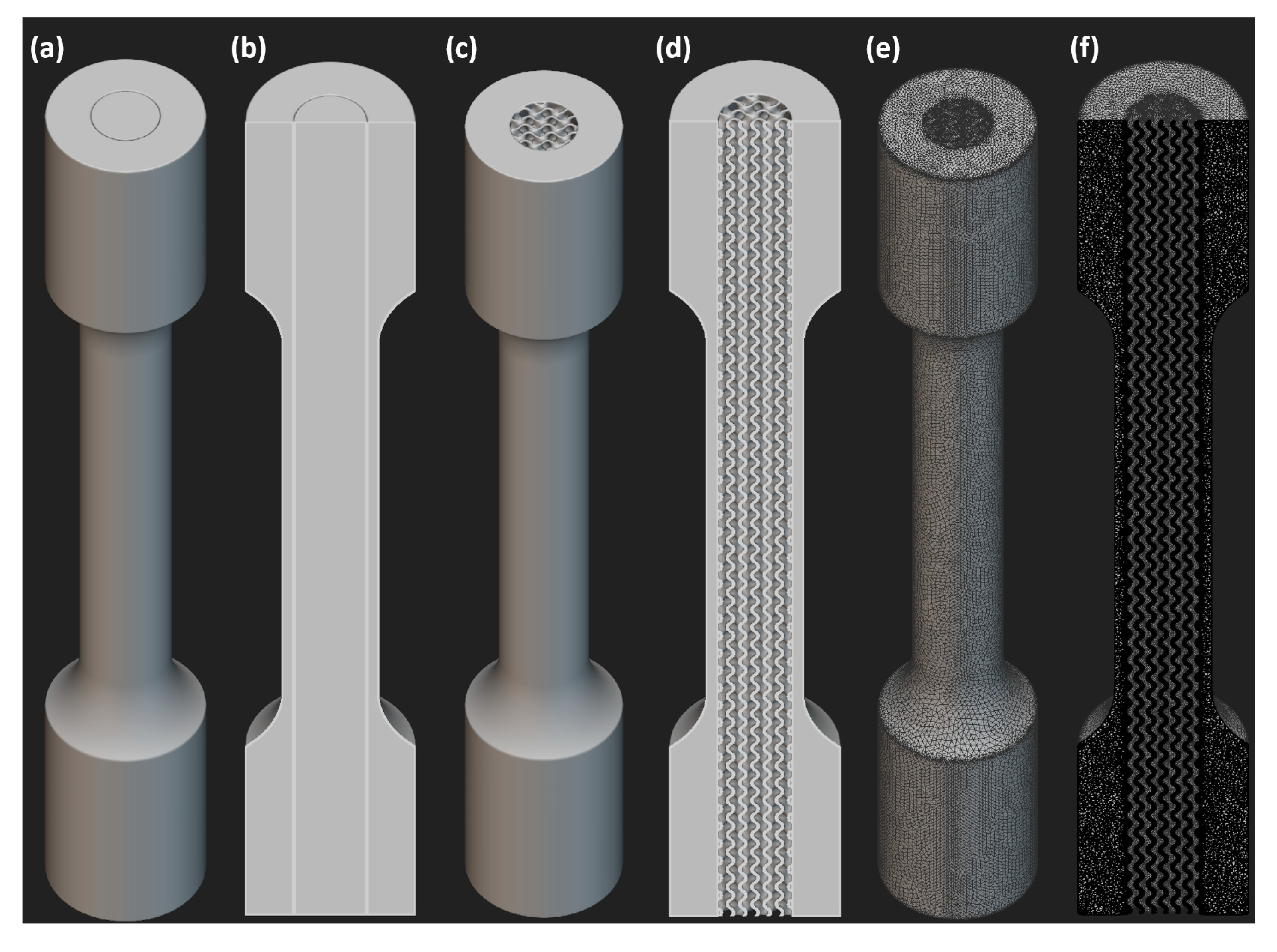
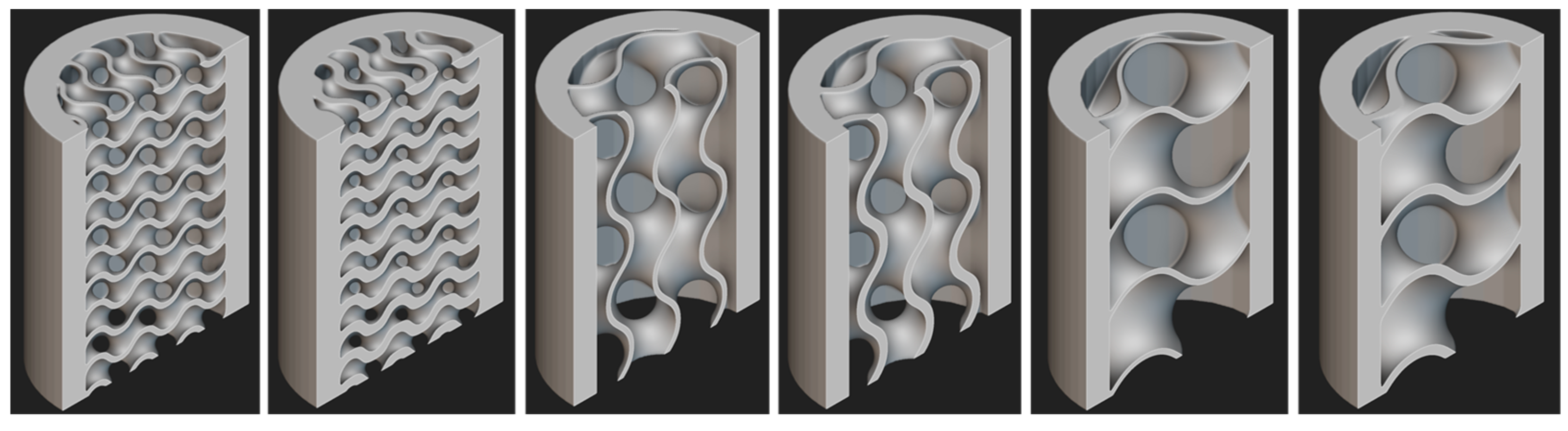
2.1. Lattice Structure Design
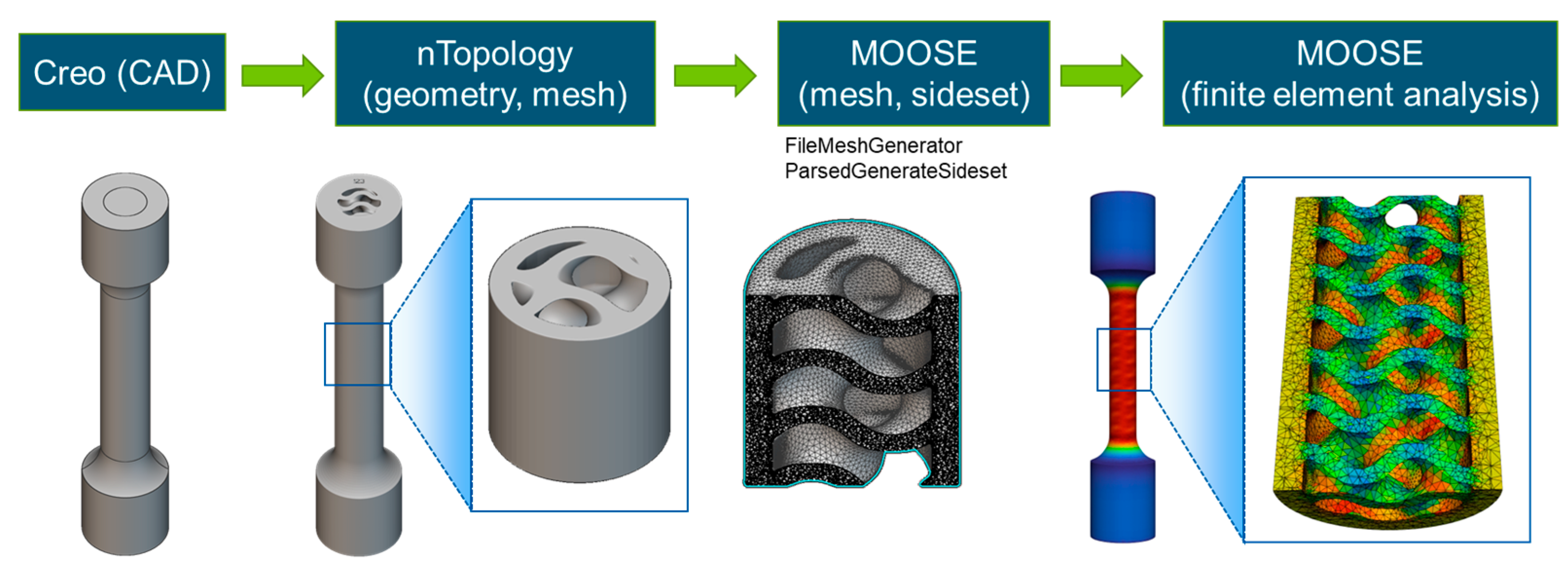
2.1.1. Creo

Additive manufacturing is defined by the American Society for Testing and Materials (ASTM) society as “a process of joining materials to make objects from 3D model data, usually layer upon layer, as opposed to subtractive manufacturing methodologies” ISO/ASTM 52900 [17]. Additive manufacturing software is a type of computer-aided design (CAD) software used in the field of 3D printing. It is typically used to generate virtual 3D models and designs that can be printed on 3D printers. This software enables users to take a digital model and fabricate a physical product from it.
In this work, the initial design of the latticed tensile bars was performed using the CAD software, Creo 8.0.7.0, as shown in Figure 1. The tensile bar dimensions were scaled down from ASTM standards so as to reduce printing time and cost. Rather than replacing the entire gauge section with a lattice structure, only the core of the gauge section was replaced with the lattice, and it was encapsulated by a solid shell, which could be machined to the desired surface finish. This ensured that the necessary surface finish could be obtained, depending on the type of testing and the standard being used. To mitigate the trapping of un-melted powder from the LPBF process, the lattice region was extended through the terminating faces of the grips to provide continuous internal channels for powder removal. In this study, the lattice design parameters, including the lattice unit cell size, lattice wall thickness, solid shell thickness, and blend radius, were varied to examine their impact on the macroscopic and local deformation tensile behavior.

2.1.2. nTopology

Although Creo is capable of generating latticed structures and the file formats required for printing (e.g., .stl files), the base version of the software is not capable of producing volumetric meshes over the latticed region, which is a necessity for finite element modelling (FEM). It was also found that the vast majority of CAD software is not well suited to produce volumetric meshes of sufficient refinement to perform FEM on lattice structures. Due, in part, to how the lattice region is explicitly defined and handled in many of the CAD programs that were tested, including Creo, SolidWorks, AutoCAD, Inventor, and Fusion360, attempted operations to mesh over the latticed region of the tensile bars resulted in memory overflows, program crashes, and computer crashes. To address this issue, a new software—nTopology 4.18.2 —was trialled, which is specifically designed to model complex structures by representing them implicitly rather than explicitly. This drastically reduces the computer resources needed to manipulate complex structures.
Using nTopology, the initial simplified models from Creo can be imported and converted into implicit bodies, which can be easily converted into latticed regions and then meshed, as shown in Figure 2. Additionally, when joining the latticed core region to the solid shell and connected grips, a blend radius can be applied to smooth the transition between the two regions so as to minimize stress concentrators. As such, the blend radius was added to the list of lattice design parameters to be optimized. Using nTopology, lattice structures with systematically varied lattice design parameters were created. Figure 3 shows that nTopology can successfully mesh unit cell, cell wall, shell, and blend radius.

2.2. Interface with Moose

While the FEM of strictly mechanical loading can be performed directly within nTopology, it will ultimately be desirable to simulate the performance of prospective nuclear reactor materials in a modeling environment, which can couple the mechanical performance with the heat and neutron transport present in a nuclear reactor. As such, a generalized pipeline and workflow were developed to construct the interface from Creo, to nTopology, to geometries and meshes that can be imported into MOOSE for FEM. The approach took advantage of the functionalities in MOOSE, FileMeshGenerator, and ParsedGenerateSideset, to add and define element side sets for setting up boundary conditions. In the simulations of tensile testing, the upper and bottom boundaries were selected uisng the input parameter “combinatorial_geometry” to define the stress-controlled boundary condition. Tests were performed to confirm that both the .unv (I-deas Universal format) and .inp (Abaqus format) file extensions produced by nTopology could be imported into MOOSE to generate the file under Sandia’s Exodus II format. The generation of a MOOSE input file for format conversion and the overall pipeline for finite element analysis are summarized in Figure 4. A tensile bar featuring a latticed core region begins as a simplified CAD mode, first built using Creo, and is imported into nTopology where latticing is performed followed by mesh generation and optimization. The resultant mesh can then be imported to MOOSE into define the boundary conditions and perform the finite element modeling.

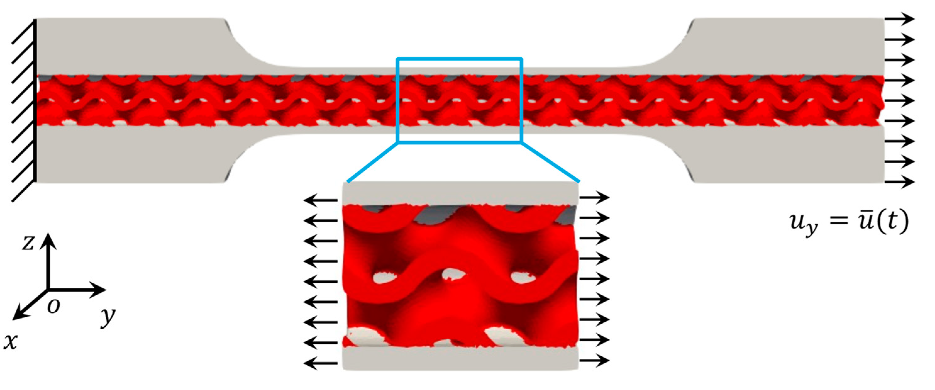
2.3. Finite Element Modeling

Idaho National Laboratory’s (INL) in-house simulation software MOOSE was employed to simulate the mechanical behavior of the tensile specimen with a gyroid structure. The tensile behavior of a representative middle section, rather than the entire tensile bar specimen, was simulated (Figure 5), which reduced the computational burden by approximately 90%. In this study, first-order tetrahedron elements (TET4) were used. The total number of elements exhibited slight variations across various gyroid structures, spanning between 1.8 × 10⁵ to 1.2 × 10⁶. To emulate the tensile process, Dirichlet boundary conditions were applied on both sides of the specimen, aligning with the direction of elongation (y-axis, as depicted in Figure 5). The specimen was then deformed at a strain rate of 5 × 10⁻⁴ s−1. To examine the mechanical behavior of the lattice structures before fracture initiation, an isotropic power-law-hardening material model was utilized with the commercial SS 316L material properties applied at every point in the material. The Young’s modulus used was 99 GPa, Poisson’s ratio was 0.35, strength coefficient was 847 MPa, and strain hardening coefficient was 0.06. To understand the effect of the gyroid lattice structure parameters on the mechanical behavior, a batch of simulations were run on gyroid structures with different unit cell sizes, blend radii (BR), and densities (or weight savings). The stress distributions of the specimens with different unit cell sizes are shown in Figure 6. The stress fields demonstrated clear patterns for each case created by their individual periodic internal structures, while the overall magnitude of the stresses did not seem to vary much across different unit cell sizes.

3. Results

3.1. Macro-Mechanical Response

To study the macro-mechanical response of the structures, the simulated stress−strain curves of the structures were compared. Figure 7 shows the simulated axial stress−strain curves for diverse structures exhibiting varying densities of internal gyroid structures. The responses of gyroids were compared with those of the solid and shell structures, respectively. Note that all gyroid structures were incorporated within an outer solid shell structure, as illustrated in Figure 3 and Figure 5. In Figure 7a,b, the term “shell” signifies the configuration where no internal structure was included. Among all three quantities of interest, density had the most significant effect on the overall macro-mechanical response of the structure. Specifically, a higher density indicated a stronger structure (higher elastic modulus) and a higher yield point (Figure 7a). Blend radius also played a role in the mechanical response of the structure, i.e., a larger blend radius made the structure stronger (Figure 7b). However, the effect of the blend radius was less dominant than the density. Lastly, the unit cell size did not play a significant role in the stress−strain response (Figure 7a,b).
To study the macro-scale response affected by the solid shell thickness, lattice region diameter, density, and unit cell size, case-by-case comparisons of the stress−strain responses of different gyroid structures are included in Figure 8. The solid shell thickness is shown to have a considerable effect on the mechanical properties of the gyroid structure. Specifically, a thicker solid shell resulted in a stiffer gyroid structure with a higher yield point (Figure 8a). Meanwhile, the stiffness of the structure decreased with an increased lattice region diameter (see Figure 8b). An increased density made the gyroid structure stiffer (Figure 8c). Nevertheless, the unit cell size did not play an obvious role in the stiffness of the structure (Figure 8d).

3.2. Micro-Mechanical Response

To investigate the micro-mechanical response of the different structures, we compared the probability density function (PDF) of the Von-Mises stress. A concentrated distribution (exhibited by a higher peak) implies a more uniform stress distribution, which indicates a lower possibility of localized stress concentration. Figure 9a shows the PDFs for different unit cell sizes (1 mm–3 mm). The 1 mm unit cell had the highest peak, indicating the most uniformly distributed stress field. The peak height increases with the decrease in unit cell size, which indicates the more evenly distributed stress field among the finer lattice structures. Therefore, it can be concluded that the unit cell size plays a role in the micro-mechanical response. Specifically, the smaller the unit cell size, the less stress concentration expected. Similarly, Figure 9b shows the PDF for different blend radii (100 µm–500 µm). With an increased blend radius, the height of the peak also increased, meaning a more uniform stress distribution. Therefore, it can be concluded that a larger blend radius would be beneficial for reducing the stress concentration.
To study the micro-scale response affected by the solid shell thickness, lattice region diameter, density, and unit cell size, similar case-by-case comparisons of the Von-Mises stress PDFs are included in Figure 10. Among all the quantities of interest, the solid shell thickness played the most significant role in the stress distributions. As shown in Figure 10a, the higher peak for the 3 mm solid shell thickness case than the 1 mm thick implied that a more evenly distributed stress field could be achieved by increasing the solid shell thickness. Figure 10b shows a very close distribution for different lattice region diameters. The smaller lattice region diameter had a slightly more even stress distribution than the larger lattice region diameter case. The density of the structure did not have a significant effect on the stress distribution either (Figure 10c). It can be observed that the 70% dense case had a slightly higher peak, indicating a more uniform stress distribution, but the difference was very small compared with the 50% dense case. On the other hand, Figure 10d shows that the unit cell size had an obvious effect on the stress distribution, and that a smaller unit cell helped make the stress field more uniform.

4. Discussion

The analysis of the macro-mechanical and micro-mechanical responses of gyroid structures in Section 3.1 and Section 3.2 reveals key insights into the various factors influencing their mechanical behavior at different scales.
The impacts of the blend radius, solid shell thickness, and lattice region diameter exhibited uniformity across both macro- and micro-scales. Optimizing the mechanical performance of a gyroid structure involved increasing the blend radius and the solid shell thickness while decreasing the lattice region diameter, all within the constraints of geometry and manufacturing.
Elevating the internal gyroid structure’s density significantly enhanced the structure’s elastic modulus and yield point (see Figure 11), yet its contribution to stress distribution at the micro-scale was limited. This limitation was inherent in the nature of density, representing the average mass distribution across the structural domain without capturing the intricate structural details crucial at smaller length scales. Note the 0% density denotes the scenario in which the internal gyroid structure is entirely absent, while the outer shell structure remains included.
Reducing the unit cell size proved effective at achieving a more uniformly distributed stress across the entire structure, mitigating point failures. While its impact on macro-scale performance was less pronounced, this could be attributed to the unit cell size primarily influencing the local intricacies of the gyroid structure.
Furthermore, the absence of defects in the simulated structure and current lack of a damage/fracture mechanism in the model underscores a potential adverse effect on the localized factors’ contribution to the macro-scale behavior of the structure. Recognizing these nuances is essential for a comprehensive understanding of gyroid structures, guiding efforts towards optimizing design and performance.

5. Conclusions

This study investigated the relevant lattice design parameters for lattice topology optimization of load-bearing structures. Tensile test specimens with different relative densities, unit cell parameters, and solid shell thickness were designed. Finite element modelling was carried out to predict the tensile stress of the lattice structure created. It was found that:
  • It is important to use the appropriate software for lattice design. nTopology could successfully mesh the unit cell, cell wall, solid shell, blend radius, and lattice type.
  • A generalized pipeline and workflow were developed to construct the interface from Creo, using nTopology, to geometries and meshes that could be imported into MOOSE for FEM analysis.
  • FEM analysis proves valuable for assessing the influence of a wide range of factors on the design of gyroid structures.
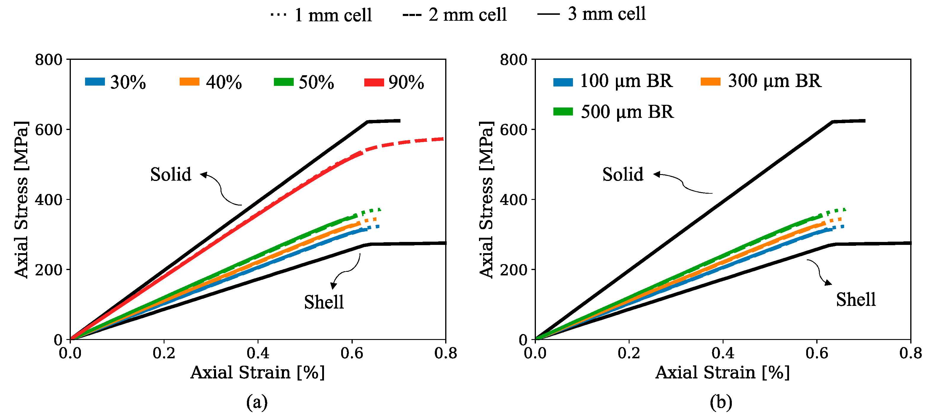
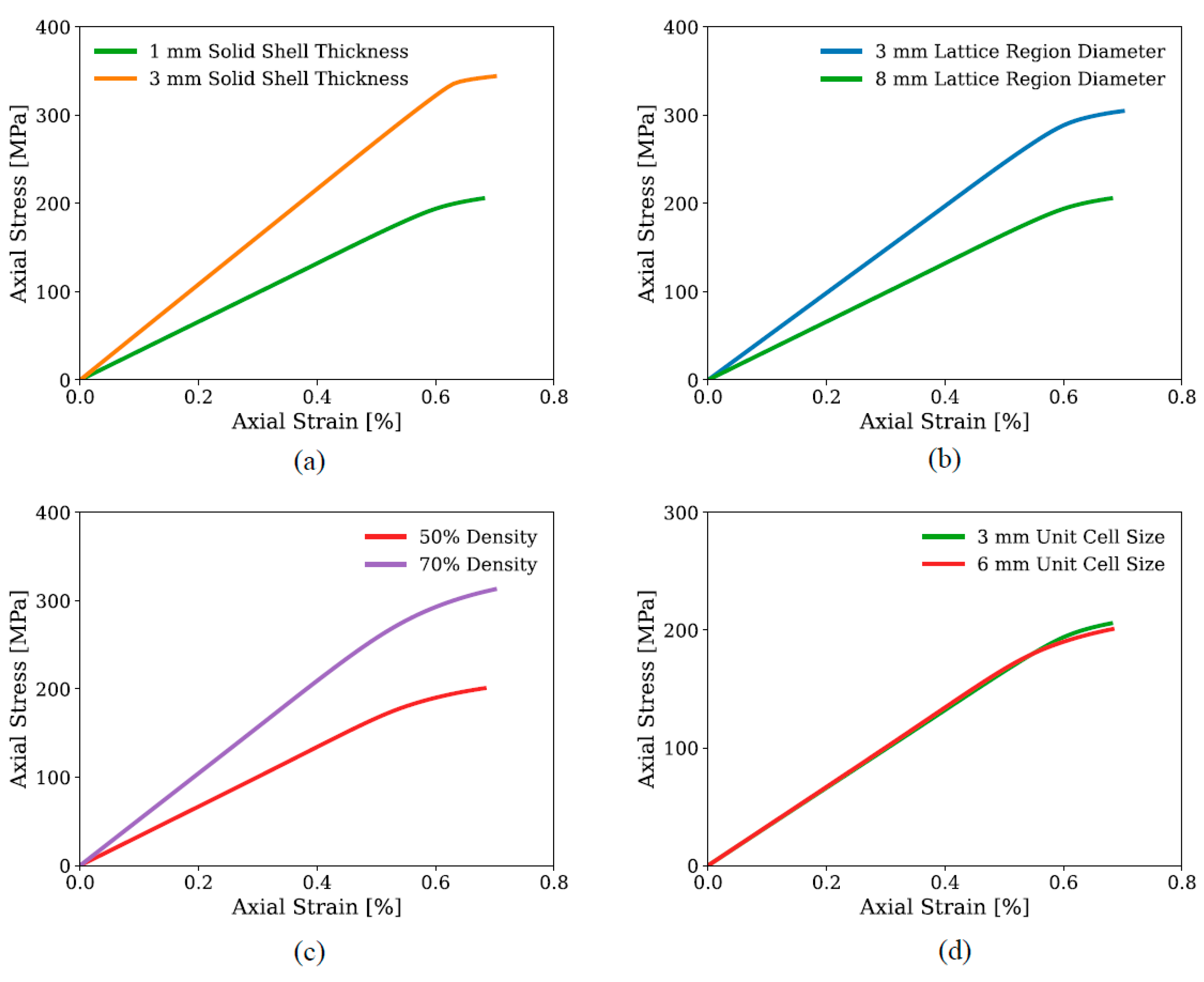
  • Enhancing the mechanical performance at both macro- and micro-scales was facilitated by increasing the blend radius and solid shell thickness, while simultaneously decreasing the lattice region diameter within practical constraints.
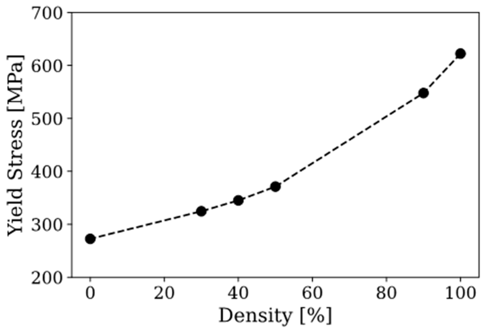
  • Density plays a crucial role in macro-scale performance by improving the elastic modulus and yield point.
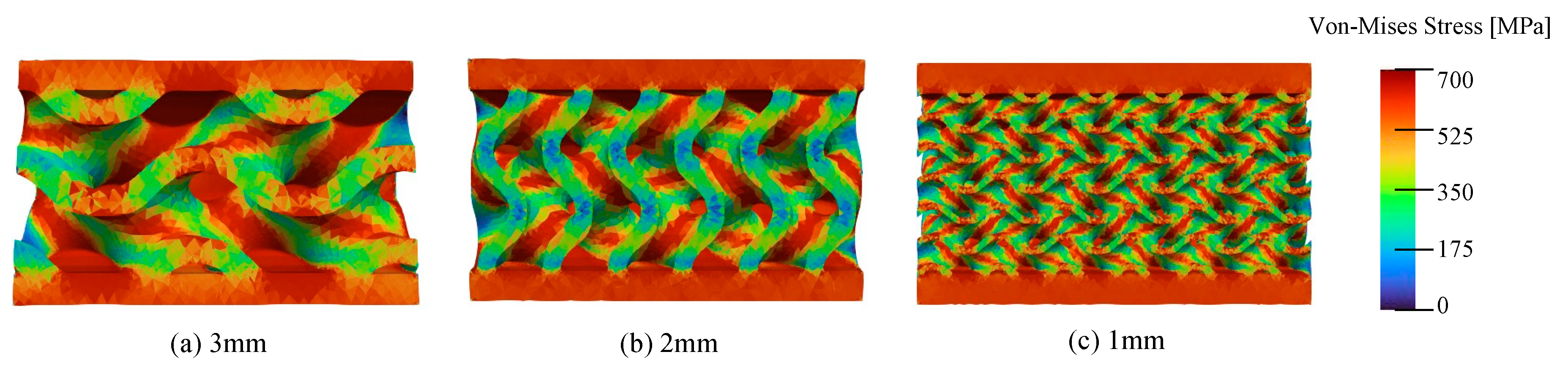
  • Decreasing the unit cell size promotes a more uniform stress distribution at the micro scale.
These results provide a design basis for selecting the appropriate lattice parameters for developing and optimizing the topology of load-bearing structures. Future work includes validation of the process pipeline and modeling methodology via mechanical testing of additively manufactured samples comprising the different lattice structure parameters identified from the work herein as having the most significant effects on the mechanical behavior.

Author Contributions

Conceptualization, R.S.; methodology, R.S., M.M., D.Y. and J.-H.K.; software, M.M., D.Y. and J.-H.K.; validation, R.S., M.M., D.Y. and J.-H.K.; investigation, R.S., M.M., D.Y. and J.-H.K.; writing—original draft preparation, R.S.; writing—review and editing, M.M., D.Y. and J.-H.K.; visualization, R.S.; supervision, R.S.; project administration, R.S.; funding acquisition, R.S. All authors have read and agreed to the published version of the manuscript.

Funding

This work was supported through the Idaho National Laboratory (INL) Laboratory Directed Research& Development (LDRD) Program under Department of Energy (DOE) Idaho Operations Office Contract DE-AC07-05ID14517.

Data Availability Statement

Data is contained within the article.

Conflicts of Interest

The authors declare that they have no known conflicts of interest.

References

  1. Agarwal, V.; Ballout, Y.; Gehin, J. Fission Battery Initiative: Research and Development Plan. January 2021, INL/EXT-21-61275, DE-AC07-05ID14517. Available online: https://www.osti.gov/servlets/purl/1834302 (accessed on 9 January 2024).
  2. Forsberg, C.; Foss, A.W. Fission battery markets and economic requirements. Appl. Energy 2023, 329, 120266. [Google Scholar] [CrossRef]
  3. Hailu, Y.M.; Nazir, A.; Lin, S.C.; Jeng, J.Y. The Effect of Functional Gradient Material Distribution and Patterning on Torsional Properties of Lattice Structures Manufactured Using MultiJet Fusion Technology. Materials 2021, 14, 6521. [Google Scholar] [CrossRef] [PubMed]
  4. Pan, C.; Han, Y.; Lu, J. Design and Optimization of Lattice Structures: A Review. Appl. Sci. 2020, 10, 6374. [Google Scholar] [CrossRef]
  5. Seharing, A.; Azman, A.H.; Abdullah, S. A review on integration of lightweight gradient lattice structures in additive manufacturing parts. Adv. Mech. Eng. 2020, 12, 1687814020916951. [Google Scholar] [CrossRef]
  6. Doodi, R.; Gunji, B.M. Prediction and experimental validation approach to improve performance of novel hybrid bio-inspired 3D printed lattice structures using artifcial neural networks. Sci. Rep. 2023, 13, 7763. [Google Scholar] [CrossRef] [PubMed]
  7. Charkaluk, E.; Chastand, V. Fatigue of Additive Manufacturing Specimens: A Comparison with Casting Processes. Proceedings 2018, 2, 474. [Google Scholar] [CrossRef]
  8. Chen, S.G.; Gao, H.J.; Zhang, Y.D.; Wu, Q.; Gao, Z.H.; Zhou, X. Review on residual stresses in metal additive manufacturing: Formation mechanisms, parameter dependencies, prediction and control approaches. J. Mater. Res. Technol. 2022, 17, 2950–2974. [Google Scholar] [CrossRef]
  9. Al-Maharma, A.; Patil, S.P.; Markert, B. Effects of porosity on the mechanical properties of additively manufactured components: A critical review. Mater. Res. Express 2020, 7, 122001. [Google Scholar] [CrossRef]
  10. Lewandowski, J.J.; Seifi, M. Metal Additive Manufacturing: A Review of Mechanical Properties. Annu. Rev. Mater. Res. 2016, 46, 151–186. [Google Scholar] [CrossRef]
  11. Lam, T.N.; Chen, K.M.; Tsai, C.H.; Tsai, P.I.; Wu, M.H.; Hsu, C.C.; Jain, J.; Huang, E.W. Effect of Porosity and Heat Treatment on Mechanical Properties of Additive Manufactured CoCrMo Alloys. Materials 2023, 16, 751. [Google Scholar] [CrossRef] [PubMed]
  12. Kan, W.H.; Chiu, L.N.S.; Lim, C.V.S.; Zhu, Y.; Tian, Y.; Jiang, D.; Huang, A. A critical review on the effects of process-induced porosity on the mechanical properties of alloys fabricated by laser powder bed fusion. J. Mater. Sci. 2022, 57, 9818–9865. [Google Scholar] [CrossRef]
  13. Weeger, O.; Valizadeh, I.; Mistry, Y.; Bhate, D. Inelastic finite deformation beam modeling, simulation, and validation of additively manufactured lattice structures. Addit. Manuf. Lett. 2023, 1, 100111. [Google Scholar] [CrossRef]
  14. Yang, L.; Mertens, R.; Ferrucci, M.; Yan, C.; Shi, Y.; Yang, S. Continuous graded Gyroid cellular structures fabricated by selective laser melting: Design, manufacturing and mechanical properties. Mater. Des. 2019, 162, 394–404. [Google Scholar] [CrossRef]
  15. Yin, H.; Zhang, W.; Zhu, L.F.; Meng, F.; Liu, J.; Wen, G. Review on lattice structures for energy absorption properties. Compos. Struct. 2023, 304, 116397. [Google Scholar] [CrossRef]
  16. Lindsay, A.D.; Gaston, D.R.; Permann, C.J.; Miller, J.M.; Andrš, D.; Slaughter, A.E.; Kong, F.; Hansel, J.; Carlsen, R.W.; Icenhour, C.; et al. 2.0-MOOSE: Enabling massively parallel multiphysics simulation. SoftwareX 2022, 20, 101202. [Google Scholar] [CrossRef]
  17. BS EN ISO/ASTM 52900:2021; Additive Manufacturing—General Principles—Fundamentals and Vocabulary. British Standards Institution Standards Limited: London, UK, 2022. Available online: https://www.iso.org/obp/ui/#iso:std:iso-astm:52900:ed-2:v1:en (accessed on 9 January 2024).
Figure 1. Cross section of latticed tensile bar generated using Creo.
Energies 17 01468 g001
Figure 2. Tensile bar models from nTopology: (a,b) original Creo model converted into implicit bodies, (c,d) latticed tensile bar, and (e,f) volumetric mesh of latticed tensile bar.
Energies 17 01468 g002
Figure 3. Examples of using nTopology for lattice design with different parameters.
Energies 17 01468 g003
Figure 4. The developed pipeline allows for the construction of geometries and meshes that can be imported to MOOSE for finite element analysis.
Energies 17 01468 g004
Figure 5. Boundary condition utilized to simulate uniaxial tension of the specimen. (top) Full tensile bar includes about 3 million degrees of freedom. (bottom) Middle of the sample includes about 0.3 million degrees of freedom, while being representative of the response of a full tensile bar.
Energies 17 01468 g005
Figure 6. Von-Mises stress fields of specimens with different unit cell sizes. All three structures are 40% dense.
Energies 17 01468 g006
Figure 7. Stress−strain response of different gyroid structures compared with the solid material and shell only. (a) Different densities, unit cell sizes with 100 µm blend radius and (b) different blend radii, unit cell sizes with 90% density (10% weight saving).
Energies 17 01468 g007
Figure 8. Stress−strain response of different gyroid structures considering effects from different: (a) solid shell thicknesses (at the lattice region diameter), (b) lattice region diameters (at the same solid shell thickness), (c) densities, and (d) unit cell sizes.
Energies 17 01468 g008
Figure 9. Probability density function of the Von-Mises stress. (a) Different unit cell sizes with 500 µm blend radius and (b) different blend radii with 1 mm unit cell size. All cases are 90% dense.
Energies 17 01468 g009
Figure 10. Probability density function of the Von-Mises stress response of different gyroid structures, considering effects from different (a) solid shell thicknesses, (b) lattice region diameters, (c) densities, and (d) unit cell sizes.
Energies 17 01468 g010
Figure 11. Yield stress of the gyroid structure with different densities. Note 100% and 0% densities represent solid and shell structures, respectively.
Energies 17 01468 g011
Disclaimer/Publisher’s Note: The statements, opinions and data contained in all publications are solely those of the individual author(s) and contributor(s) and not of MDPI and/or the editor(s). MDPI and/or the editor(s) disclaim responsibility for any injury to people or property resulting from any ideas, methods, instructions or products referred to in the content.

