Review

Enhancing Biodiesel Production: A Review of Microchannel Reactor Technologies

1
Carbon Neutrality Research Group, University of Southampton Malaysia, Iskandar Puteri 79100, Malaysia
2
China-UK Low Carbon College, Shanghai Jiao Tong University, Lingang, Shanghai 201306, China
*
Author to whom correspondence should be addressed.
Energies 2024, 17(7), 1652; https://doi.org/10.3390/en17071652
Submission received: 31 January 2024 / Revised: 18 March 2024 / Accepted: 26 March 2024 / Published: 29 March 2024
(This article belongs to the Special Issue Sustainable Biofuels for Carbon Neutrality)

Abstract

:
The depletion of fossil fuels, along with the environmental damages brought by their usage, calls for the development of a clean, sustainable and renewable source of energy. Biofuel, predominantly liquid biofuel such as biodiesel, is a promising alternative to fossil fuels, due to its compatible direct usage within the context of compression ignition engines. However, the industrial production of biodiesel is far from being energy and time efficient, which contributes to its high production cost. These inefficiencies are attributed to poor heat and mass transfer of the transesterification reaction. The utilisation of microchannel reactors is found to be excellent in escalating heat and mass transfer of the reactants, benefitting from their high surface area-to-volume ratio. The microchannel also intensifies the mixing of reactants via the reactor design, micromixers and the slug flow patterns within the reactor, thus enhancing the contact between reactants. Simulation studies have aided in the identification of mixing regimes within the microchannel reactors, induced by various reactor designs. In addition, microwave irradiation heating is found to enhance biodiesel production by localised superheating delivered directly to the reactants at a molecular level. This enables the reaction to begin much earlier, resulting in rapid biodiesel production. It is postulated that the synergy between microchannel reactors and microwave heating would catapult a pathway towards rapid and energy-efficient biodiesel production by enhancing heat and mass transfer between reactants.

1. Introduction

The increasing energy demand from coal, natural gas and oil are the major negative contributors to global warming and climate change, which are the two alarming crises of today [1]. Other environmental issues associated with the usage of fossil fuels include the emission of greenhouse gases (GHGs), thinning of the ozone layer and air pollution [2]. Cumulatively, the global electricity production in 2021 emitted 13 gigatonnes of carbon dioxide (Gt CO2), which contributes to one-third of the global CO2 emission related to energy [3]. On another note, the increasing energy demand also accelerates the depletion of fossil fuels.
In the past three years, the global energy scenario was strongly influenced by the COVID-19 pandemic. There was an oversupply of fuel due to lower demand, caused by slow-moving economies. During this period, the oil price dropped to an average of USD 44 per barrel. Currently, global economies are improving gradually. Demand for coal in 2021 increased to 5640 million tonnes of coal equivalent (Mtce). This was caused by the drastic increase in coal-fired electricity production, as global economies improved after the pandemic [4].
However, the Russia–Ukraine conflict in February 2022 dampened the recovery of the global economy after the pandemic, which further complicated the global energy situation. As a result, fuel prices hiked to an average of USD 105 per barrel in 2022 [5]. This affected the supply of natural gas the most, especially to Europe. Russia had cut approximately 80% of its natural gas pipeline flows to the European Union [6]. As a result, Europe needed to import an additional 50 billion cubic metres (bcm) of liquefied natural gas (LNG) in 2022 compared to 2021 to compensate for the fuel shortage [7]. This has caused a shortage of LNG to other Asian importers, despite the lower demand from China currently due to its pandemic-induced slow-moving economy.
Globally, measures such as the Kyoto Protocol in 1997 [8] and the Paris Agreement in 2015 [9] have been implemented to curb the effects of fossil fuel combustion by promoting the usage of renewable energy. These agreements require nations to comply with the set greenhouse gas emission limits to control climate change. Furthermore, many countries around the globe have set respective regulations to ensure the utilisation of clean energy, in line with the current energy scenario [2]. A few examples would be the National Action Plan on Climate Change by India [10], the Climate Change Act by the United Kingdom [11], the Italian National Energy Strategy by Italy [12] and the Renewable Energy Sources Act by Germany [13].
Moving forward, the need for clean and sustainable energy is a necessity in the present moment and the future [14]. To achieve this, multiple options for renewable energies are available such as solar, hydropower, biomass, biofuel and wind energy. Figure 1 shows a forecasted global renewable energy map in the year 2050, with a total final energy consumption of 222 exajoules (EJ) [15]. Apart from wind and solar, liquid biofuel is forecasted to be the third-highest contributor towards renewable energy, and it will constitute 10% of global renewable energy sources by 2050. Liquid biofuels such as biogas, biodiesel and bioethanol serve as excellent sources of renewable energy to curb the depletion of fossil fuels and the disadvantages that come along with the usage of fossil fuels simultaneously [16]. This is due to the easy availability of raw materials and reactants, the high energy density of biofuels and the pre-existing infrastructure for biofuel production.
Biodiesel offers several advantages in comparison with other liquid biofuels. Within the context of diesel engines, biodiesel has an advantage, offering direct usability without any engine modification required [17]. This is possible as biodiesel has similar chemical and physical properties as petroleum diesel, such as viscosity, ignition properties and energy content. Other than that, the usage of biodiesel accounts for various environmental benefits such as lower emissions of unburned hydrocarbons, carbon dioxide, carbon monoxide, nitrogen oxide and exhaust particles [18]. Furthermore, biodiesel is also a sustainable source of energy, especially in the Southeast Asian region. Vegetable oil such as palm oil is the raw material for the production of first-generation biodiesel [19]. Southeast Asian countries like Malaysia are among the world’s largest palm oil producers, hence enabling an uninterrupted supply of raw material for biodiesel production [20].
Nevertheless, all production processes of feedstocks such as vegetable oils, non-edible oils and animal fats are subjected to environmental emissions. This means that the utilisation of palm oil as feedstock for biodiesel production is an indefinite measure for producing a ‘green’ source of biofuel. Therefore, the life cycle assessment of feedstocks is crucial as a comprehensive measure in determining the environmental effects of the production process in terms of carbon dioxide emission. In addition to cost-, time- and energy-efficient biodiesel production methods, it is noteworthy that the environmental implication of feedstocks plays a prominent role in producing an environmentally friendly fuel source as a whole.
Biodiesel is known as a liquid biofuel that contains mono-alkyl esters of long-chain fatty acids, obtained from vegetable oils or animal fats [21]. Biodiesel can be produced through a variety of physical and chemical methods. Among physical methods for biodiesel production, direct blending or dilution was a pioneer practice. This method includes directly blending petroleum diesel with vegetable oil in various ratios. The main reason for the discontinuation of this method was the solidification of the highly viscous vegetable oil in cold weather. Other disadvantages included the high free fatty acid content, gum formation and low volatility of vegetable oil that led to engine malfunction, such as improper atomisation, plugging of injector nozzles and incomplete fuel combustion [2]. Microemulsion is another physical method for biodiesel production, formed by the mixture of solvents and triglycerides to attain a clear and stable dispersion of fuel with surfactants. However, immense carbon deposition, improper fuel combustion and the poor efficiency of biodiesel produced via microemulsion resulted in this method being unpopular [22].
Pyrolysis or thermal checking is a chemical method for biodiesel production which involves converting organic materials at extreme reaction temperatures in the absence of oxygen. Pyrolysis is considered obsolete for biodiesel production in current times since it is costly and requires complex equipment, and the output resembles petrol rather than diesel [23]. Meanwhile, the transesterification reaction is the most widely used chemical method for biodiesel production [1], as this process enables simple and high-yield biodiesel production at a low cost compared to other methods. In the transesterification reaction, triglycerides chemically react with alcohol in the presence of a catalyst to form biodiesel and glycerol as a by-product [24]. Unreacted triglycerides and alcohol can be recovered and reused, which aids in lowering the biodiesel production cost. Moreover, glycerol (by-product) could be recovered to be sold or repurposed.
The transesterification process requires a catalyst to drive the reaction by lowering the required activation energy. While various transesterification catalysts exist, the most common categories include acid and base catalysts. Acid catalysts like sulphuric acid are usually utilised for feedstock with high free fatty acids (FFAs) beyond 1–2% FFA content, such as waste cooking oil (WCO). This is because acid catalysts are inert towards the FFAs in feedstock [25]. Base catalysts, however, react with high-FFA feedstocks to form soap in a process known as saponification. Hence, base catalysts are suitable for catalysing biodiesel production using low-FFA-content feedstocks. Among common base catalysts utilised for biodiesel production are potassium hydroxide, sodium hydroxide and calcium oxide [21].
Efficient biodiesel production is dependent on various reaction parameters that include the alcohol-to-oil molar ratio, percentage of catalyst loading, reaction time, reaction temperature and mixing speed [18]. Industrial biodiesel production involves controlling these reaction parameters in large-scale biodiesel reactors. Figure 2 shows an overview of chemical reactors used for biodiesel production.
Commercially, biodiesel is commonly produced using stirred tank reactors (STRs) [26]. However, despite technological development and the prevalence of commercial STRs, the biodiesel production process is far from being energy and cost efficient. The reaction time of biodiesel production in an STR is typically between 1 and 2 h as reported by researchers [27]. Reaction kinetics in STRs is rather slow due to poor heat and mass transfer. This is due to the low surface area-to-volume ratio of reactants in STR batch reactors; hence, long reaction time and high heat energy are required to achieve high biodiesel yields [28]. Thus, the production process is not efficient and cost savvy, although a high yield of biodiesel is achievable [1]. Other reactors reported for biodiesel production include membrane reactors that require 1 to 3 h of reaction time [29], packed-bed reactors with 2 to 3 h of reaction time [30], and oscillatory baffled reactors with a reaction time of 0.5 h [29]. However, these reactors are time and energy inefficient, which would reflect on the biodiesel production cost as well.
Hence, there are several limitations of biodiesel production via the transesterification reaction. Poor production efficiency of biodiesel is caused by the heat and mass transfer limitations of the reactants. This results in a lengthier time taken for the reaction to begin. The conventional mixing process of reactants in industrial reactors inhibits the reaction from beginning instantaneously due to inefficient mixing and heat transfer. Current processes require high energy utilisation for high-yield biodiesel production; however, most energy is lost to the surroundings via conduction and convection. Furthermore, industrial biodiesel production in commercial STR batch reactors reduces production efficiency by hindering continuous production. Also, the long time needed (about 4 h) for gravitational by-product (glycerol) separation at the end of the reaction contributes to the inefficiency of the current biodiesel production process. In short, the current industrial production of biodiesel is far from being energy and time efficient, as the amount of time and energy invested is not proportionate to the biodiesel produced in return.
Thus, this review focuses on the utilisation of microchannel reactors for biodiesel production, by which heat and mass transfer of the reaction could be enhanced. Several segments of the microchannel reactor, which include the reactor design, the influence of micromixers and the heat delivery mechanism within the reactor, are discussed. Next, the flow of reactants within the microchannel reactor is discussed, focusing on the formation of reactant slugs and their mass transfer. This review also includes flow patterns and findings from simulation studies on the usage of microchannel reactors for biodiesel production. Also jointly reviewed are the challenges faced by the utilisation of microchannel reactors. Finally, the potential future direction for biodiesel production in microchannel reactors is explored in combination with microwave heating.

2. Microchannel Reactor

This section discusses the usage of microchannel reactors for biodiesel production. The design of microchannel reactors, the types of micromixers and the heat delivery mechanism of reactants are jointly reviewed.

2.1. Microchannel Reactors for Biodiesel Production

Research on the utilisation of microchannel reactors for biodiesel production is currently the focus of researchers. This is due to the ability of microchannel reactors to significantly enhance heat and mass transfer between reactants, attained through the high surface area-to-volume ratio within the microchannel and the intensified mixing effect of reactants [31]. As a result, energy- and time-efficient biodiesel production of high yield is achievable. Table 1 summarises the recent usage of microchannel reactors for biodiesel production from 2020 to 2023, including details on the different microchannel reactor features for biodiesel production using various feedstocks, catalyst choices and reaction conditions.
Akkarawatkhoosith et al. [32] reported a recent biodiesel production study in a microchannel reactor using rice bran oil fatty acid distillate as feedstock. The microchannel reactor consisted of a T-mixer and an internal diameter of 0.9 mm. A furnace was used to heat the reaction to a temperature of 280 °C. A biodiesel yield of 93% was achieved within 19 min using 0.4 wt.% sulphuric acid to catalyse the reaction. In comparison with batch processes, this study resulted in a more energy-efficient and continuous biodiesel production due to the high surface area-to-volume ratio of the microchannel reactor that enhanced the rate of heat and mass transfer of the reaction.
Yusuf et al. [34] investigated the potential of three microchannel reactor designs for biodiesel production with vegetable oil. The microchannel reactors were fabricated via laser etching on polymethyl methacrylate acrylic sheets with varying designs: (1) T-mixer, (2) Y-mixer and (3) Tesla-shaped. The transesterification reaction was carried out with a sodium hydroxide catalyst loading of 1.0 wt.%, while a water bath was used to maintain a reaction temperature of 60 °C. The best biodiesel yield of 97.9% was achieved by the Tesla-shaped microchannel design at 4.85 s, while the T-mixer and Y-mixer designs had biodiesel yields of 93.3% and 94.3%, respectively. The effectiveness of the Tesla-shaped design was due to its design geometry comprising grooves and valves, which promoted superior mixing efficiency of reactants.
Aghel et al. [38] reported the utilisation of a 1 cm3 microchannel reactor for the biodiesel conversion of waste cooking oil. The microchannel reactor was connected to a T-mixer equipped with peristaltic pumps to flow reactants through the reactor. A mixture of waste cooking oil and a calcined cow bone-supported KOH catalyst with an 8.5 wt.% concentration was fed into the reactor from one end of the T-mixer, whereas a mixture of methanol and toluene was fed in from another end. In this study, toluene was used as a co-solvent to improve the solubility of methanol and oil. A temperature-controlled hot water bath system maintained the reaction temperature at 63.53 °C. An optimum biodiesel yield of 97.21% was obtained in a reaction time of 85 s.
Mohadesi et al. [40] conducted a semi-industrial pilot study of biodiesel production in microchannel reactors using waste cooking oil. The set up included reservoirs, distributors, micromixers and microtubes of 800 mm. Reactant-holding reservoirs were equipped with peristaltic pumps to enable flow rate adjustment into the distributor. The distributors then split the reactants into 50 flow streams before channelling each stream into its respective T-mixers. The output of each T-mixer was then connected to microchannel reactors of 5 m long microtubes. The study revealed a 96.58% biodiesel yield at an oil-to-methanol volumetric ratio, reaction temperature, reaction time and catalyst loading of 5:2.15, 60 °C, 12.5 min and 7.87 wt.% kettle limescale deposit, respectively. The high biodiesel yield obtained was in line with the hypothesis of this study, where microchannel reactors offer higher biodiesel yield and enable easier manoeuvring in the industry.
Mohadesi et al. [36] reported a 99.24% biodiesel conversion from waste cooking oil in a stainless steel microchannel reactor in the presence of a heterogeneous base catalyst. The reactor had an internal diameter of 0.8 mm and a volume capacity of about 1 cm3. Reactants were fed into the reactor via a T-mixer using a peristaltic pump, and a reaction temperature of 63.1 °C was maintained via a bain-marie bath, as shown in Figure 3. Since the utilisation of heterogeneous catalysts generally requires long reaction times, the microchannel reactor was successful in containing the reaction time within 60 s at optimised conditions.
The utilisation of a 1 m long microchannel reactor for biodiesel conversion was reported by Thangarasu et al. [42] using Aegle Marmelos Correa seed oil as feedstock. The experimental set up included an electrically heated water bath and ultrasonic pre-mixing of reactants. The transesterification reaction was catalysed by 1.3 wt.% sodium methoxide at an oil-to-methanol molar ratio of 1:9, and a reaction temperature of 48 °C was maintained throughout. The effect of two different internal diameters of the microchannel reactor was studied. The reactor with a 0.8 mm internal diameter achieved a 91.8% biodiesel yield at 25 s, whereas the reactor with a 0.3 mm internal diameter achieved a 98.0% yield within 15 s. The higher yield obtained by the microchannel reactor with the smaller internal diameter of 0.3 mm was due to its higher surface area-to-volume ratio, which promoted better contact and mixing of reactants during the reaction.
Pavlovic et al. [39] investigated the potential of a custom-made microchannel reactor to facilitate the transesterification reaction of biodiesel production. The microchannel reactor had an internal diameter of 0.8 mm and a length of 800 mm, and it was made of Teflon. The experimental set up included a T-mixer equipped with syringe pumps to deliver reactants into the reactor as shown in Figure 4. The transesterification reaction was carried out using sunflower oil as feedstock with an oil-to-methanol volume ratio of 3:1, in the presence of a calcined waste chicken eggshell-derived calcium oxide catalyst. A biodiesel yield of 51.2% was obtained at a reaction time of 10 min. The effectiveness of the microchannel reactor was proven when a lower biodiesel yield (18.6%) was obtained when the transesterification reaction was repeated at similar reaction conditions in a stirred batch reactor.
Another semi-industry pilot study using a microchannel reactor was conducted by Mohadesi et al. [18] for biodiesel production via the transesterification reaction of waste cooking oil. The microchannel reactor had an internal diameter of 0.8 mm and a length of 5 m. The oil and methanol were fed into individual T-mixers, and then into the microchannel reactors via peristaltic pumps, upon distribution into 50 channels. The results report a 97.4% biodiesel yield within 13.4 min with a reaction temperature of 65 °C. In the study, 8.1 wt.% clinoptilolite-supported potassium hydroxide was used to catalyse the reaction and a 1:2.25 oil-to-methanol molar ratio was maintained. The study postulated that the utilisation of the microchannel reactor escalated the mixing of reactants, hence reducing the reaction time in return.
An experimental module incorporating a slug generator, a microchannel reactor and a camera-equipped microscope was utilised by Laziz et al. [1] for the investigation of palm biodiesel production. Oil and methoxide slugs were formed inside a luer lock T-mixer made from ethylene tetrafluoroethylene. The microchannel reactor was made from transparent fluorinated ethylene propylene with an internal diameter of 0.69 mm and a length of 1 m. During the study, the slug flow properties and slug velocity were determined via an Olympus microscope and camera, respectively. The flow rate inside the microchannel reactor was maintained at 200 mL/min, while the temperature, oil-to-methanol molar ratio and catalyst loading were maintained at 25 °C, 1:7.6 and 5 wt.% potassium hydroxide, respectively. A 98.6% biodiesel yield was reported at a reaction time of 40 s. The study indicated that the overall transesterification reaction was improved due to the enhanced mixing and mass transfer of reactants within the microchannel. This was achieved via passive mixing through slug flow within the reactor.
Yusuf et al. [43] investigated the potential of biodiesel production using sunflower oil in a microchannel reactor. The reactor had a width of 0.4 mm and a depth of 0.78 mm and was fabricated using polymethyl methacrylate via laser etching. The total volumetric capacity of the microchannel reactor was 125 mm3, while the flow rate of reactants was controlled at 50 µL per minute. The transesterification reaction was catalysed by 4 wt.% lipase enzyme at a temperature of 30 °C. As a result, a biodiesel yield of 68.90% was reported with an oil-to-methanol molar ratio of 1:2.5. Although the usage of the microchannel reactor reportedly enhanced the rate of reaction, lipase-catalysed transesterification is typically slower and has lower yield, comparatively.

2.2. Microchannel Reactor Design

Microscale chemical processes are made possible by innovations in microchannel reactors due to advancements in microfluidic technologies. Researchers have shown interest in the usage of microchannel reactors (which some may refer to as a lab-on-a-chip) due to their advantages compared to conventional batch reactors. These advantages include higher yield of the chemical processes while promoting efficient reaction kinetics, heat and mass transfer [44]. Compared to conventional batch reactors, the continuous process in microchannel reactors enables a reduction in time to below 1 min, often only requiring a few seconds to produce the desired output [45]. Furthermore, microchannel reactors have large surface area-to-volume ratios at about 20,000 m2 m−3 in contrast to conventional reactors with 1000 m2 m−3 [46].
Microchannel reactors adopt the numbering-up approach for scaling up reaction output without the need to expand the reactor dimensions. The numbering-up approach of microchannel reactors is when a cluster of multiple reactors is run concurrently, enclosed within a single module. This feature enables all optimised parameters such as reaction temperature, reaction time and flow rate of a single microchannel reactor to be applicable, regardless of stepping up the output scale [47]. Intensification of reaction yield in microchannel reactors is focused on optimising heat and mass transfer of chemical reactants [48]. This is because efficient mass transfer by enhanced molecular diffusion between chemical reactants influences the reaction yield.
The design of microchannel reactors plays an important role in achieving good mixing of reactants, which in return elevates the heat and mass transfer of the reaction. Although gaining popularity in a variety of application domains, microchannel reactors extensively benefit biological, chemical and biochemical processes [49]. Biodiesel production is a biochemical process that could benefit from the usage of microchannel reactors. Hence, in this section, the latest development of microchannel reactors is reviewed to further inspire the development of biodiesel microchannel reactors.
Wang et al. [48] reported the study of a staggered herringbone groove microchannel reactor for the alkylation process of isobutane to produce alkylate, catalysed by sulphuric acid. The alkylate produced is a superior component to increase the octane of gasoline, contributing to lower exhaust emissions. This study intended to improve the heat and mass transfer of the alkylation process via the staggered herringbone groove microchannel reactor as observed in Figure 5a. This reactor was designed to have three layers, which are the coolant channel layer, the staggered herringbone groove microchannel layer, and the bottom sheet layer that comprises the inlet and outlet nozzles as illustrated in Figure 5b. The high conversion by the herringbone groove microchannel reactor was due to efficient mass transfer induced by the intense mixing effect, indicated by the simulation results of this study. The staggered herringbone groove microchannel reactor has the potential to replace conventional batch-stirring reactors for the alkylation process, as it has efficient mass and heat transfer, enables shorter reaction time and lowers the process cost by enabling the usage of reduced reactants. Hence, this contributes to a lower conversion cost due to a reduced capital expenditure investment.
Yusuf et al. [34] reported the study of a novel Tesla-shaped microchannel reactor for the production of biodiesel. Three different shapes of microchannel reactor designs were comparatively investigated, namely the Y-shaped, T-shaped and the novel Tesla-shaped microchannel reactor, as observed in Figure 6. Four permutations of the T-shaped microchannel reactor were initially fabricated to determine optimum microchannel dimensions, following which, one Y-shaped microchannel reactor and the Tesla-shaped microchannel reactor were fabricated. The width and depth of all microchannel reactor designs were 400 μm × 400 μm. However, the number of bends, length and volume of the best-performing T-shaped and Y-shaped microchannel reactors were 10 bends, 41 cm and 0.06456 mL, respectively. On the other hand, the Tesla-shaped microchannel reactor had a total of eight bends with a length of 33 cm and a volume of 0.0970 mL.
The transesterification reaction was carried out at a reaction temperature of 60 °C, methanol-to-oil molar ratio of 9:1 and sodium hydroxide (NaOH) catalyst loading of 1 wt.%. The highest biodiesel yield of 97.8% was achieved by the Tesla-shaped microchannel reactor due to the unique geometry shape of the microchannel which comprised grooves. Convective mixing and the increase in contact between phases of reactants caused by the grooves induced efficient diffusion of reactants, which was reflected by the high biodiesel yield. The results denote that the biodiesel yield is influenced by the geometric design of microchannel reactors, which also reflects the slightly higher reaction time in the Tesla-shaped reactor.
Santana et al. [46] reported the development of a micromixer with triangular baffles and circular obstructions (MTB) microchannel reactor as observed in Figure 7a. The MTB microchannel reactor was developed for the mixing of reactants with a reduced pathway for molecular diffusion, to split and recombine the reactants within the microchannel and to generate a vortex. Multiple permutations of the microchannel dimensions were studied, with heights in the range of 200 μm to 2000 μm and widths in the range of 1500 μm to 3000 μm. The MTB microchannel reactor with the best dimension configuration was reported to have a width of 3000 μm and height of 400 μm, with the greatest biodiesel production of vegetable oil and ethanol. The highest oil conversion of 92.67% was achieved with these reactor dimensions at a residence time of 30 s.
The novelty of the MTB microchannel reactor design is the convergent–divergent segment, which is in combination with circular obstacles, as illustrated in Figure 7b. The circular obstacles served to split the flow of reactants into sub-streams. This enhanced the contact of reactants, which intensified molecular diffusion and simultaneously reduced the diffusion pathway required to achieve efficient mixing. On the other hand, the dimensions of the circular obstacles influenced the mixing efficiency of reactants where the larger the obstacle diameter, the better the mixing of reactants.

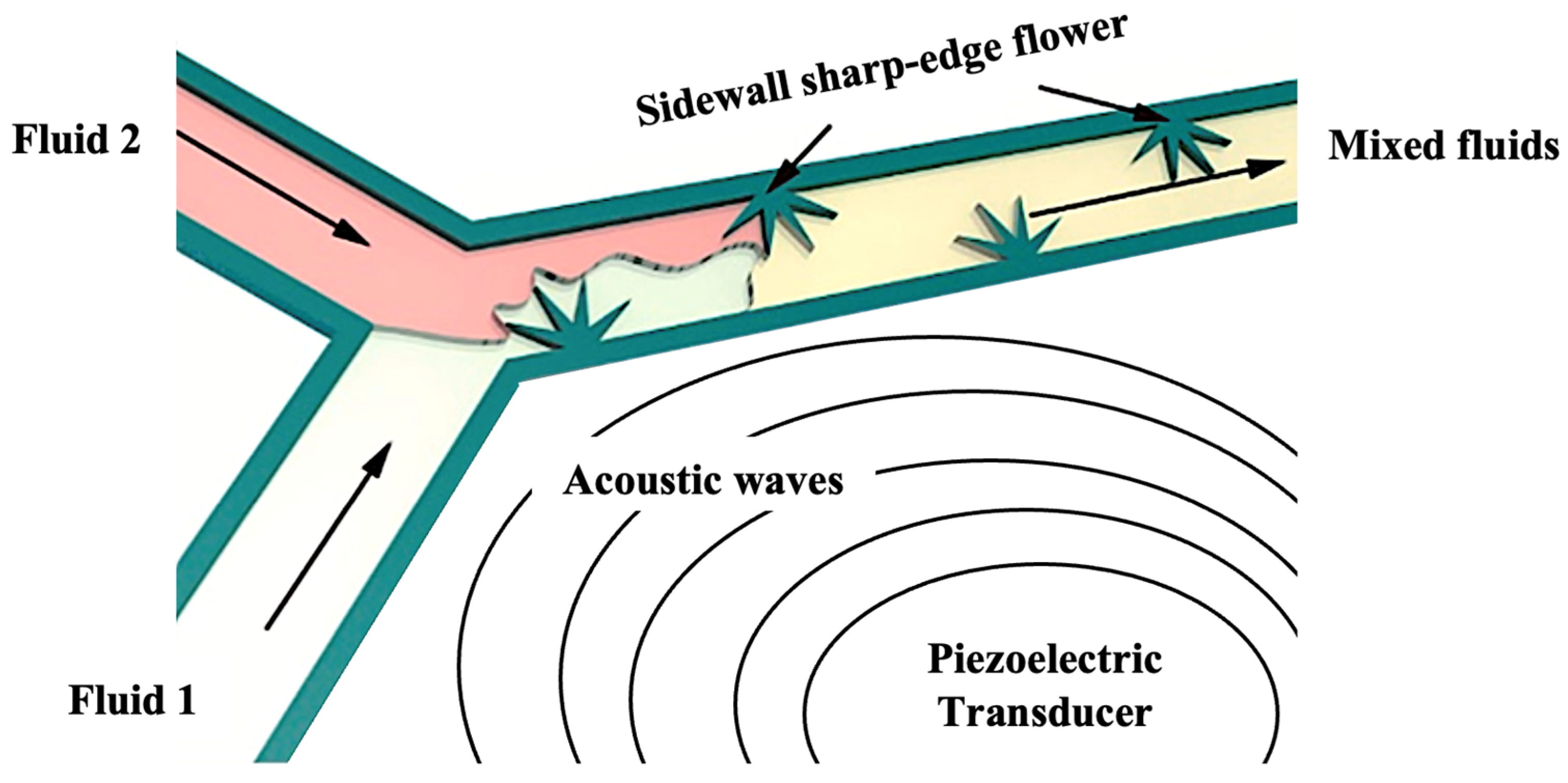
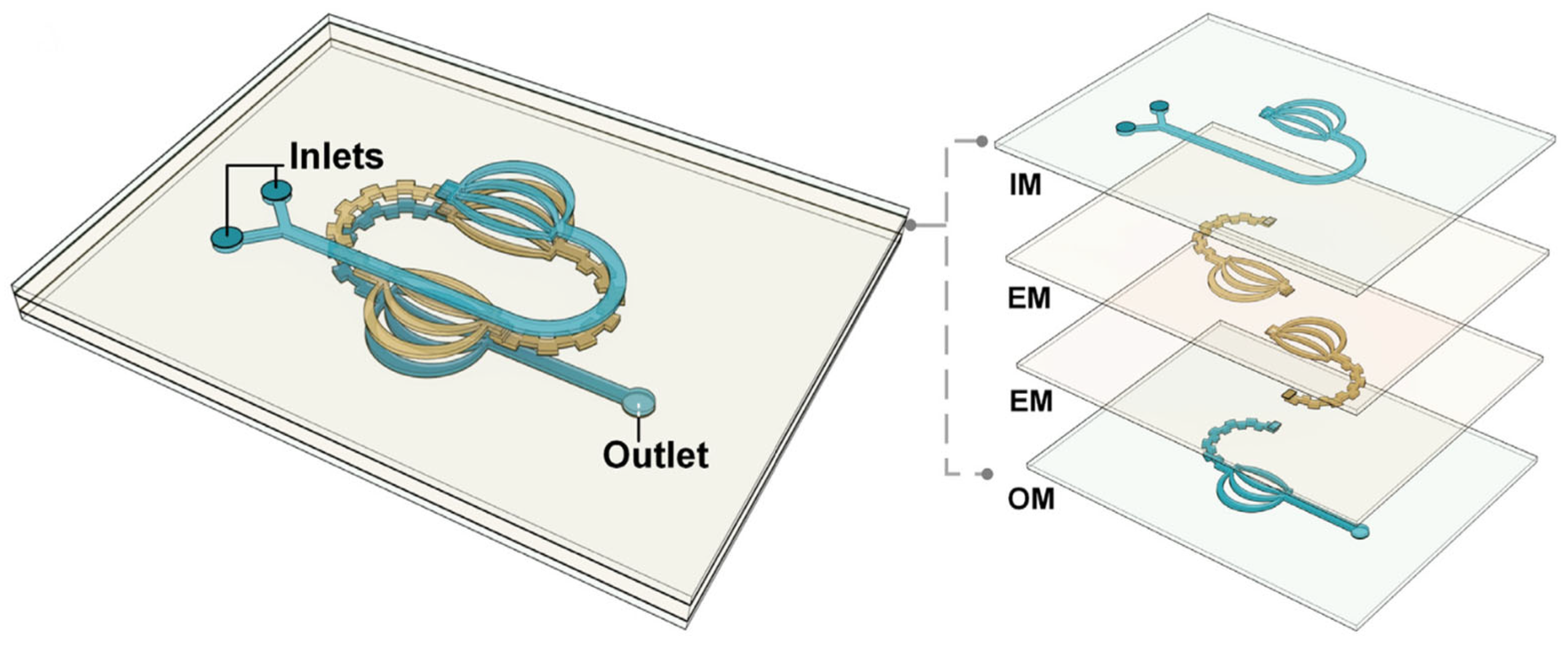
2.3. Micromixers in Microchannel Reactors

Micromixers are an essential component to achieve the mixing of two or more reactants in a microchannel reactor [50]. Micromixers determine the mixing uniformity of reactants [51]. Thus, the efficiency of micromixers influences the performance of the microchannel reactor [52]. Research focusing on processes at the microscale level has unlocked possibilities to control reaction parameters. Hence, various biochemical processes such as enzyme bioassays, nanomaterial synthesis and biochemical production involve the usage of microscale reactors to complete the process reactions. The evolution of microscale technology over the past two decades engendered homogeneous micromixing of two or more reactants to be an essential part of the process [53]. In microchannel reactors, slow flow rates at low Reynolds numbers below 10 and small microchannel dimensions (0.01 mm to 1 mm) result in laminar flow throughout the microchannel [54,55]. Hence, achieving good micro-level mixing of reactants is often dependent on strong molecular diffusion-based mixing, to attain homogeneous mixing [56].
Therefore, the incorporation of an efficient micromixer that is compatible with the type of reaction is important in a microreactor. Rapid micro-level mixing via a micromixer is crucial to obtain the desired reaction output such as chemical conversion yield, which could vary based on the reaction needs. This is because an effective micromixer promotes a higher chance of particle collision, thus increasing the rate of reaction [57]. As such, the effectiveness of micromixers determines the occurrence of the microscale reaction, while the intensity of micromixing determines the quality of the reaction and its products. Moreover, the performance of a micromixer is crucial, as poor micromixing rates would result in the formation of unwanted by-products that could jeopardise the reaction qualitatively and quantitatively [58].
Various methods are deployed to induce micro-level mixing in microreactors. These methods are generally categorised into two groups, namely active micro-level mixing and passive micro-level mixing. Table 2 summarises the latest development of micromixers in microchannel reactors for the mixing of fluid flow. The micromixer type, along with the respective method utilised by each micromixer to achieve mixing of fluid flow, is tabulated.
The main difference between active micro-level mixing and passive micro-level mixing is that active micro-level mixing involves the intervention of an external energy source to promote mixing, whereas passive micro-level mixing does not require external energy [59]. The external energy sources of active micro-level mixing are in the form of acoustic, ultrasonic, magnetic and electric energy [60]. These active micromixers integrate into the microreactor to induce micromixing by creating turbulence in fluid flow. Furthermore, active micromixers are also capable of actively controlling the intensity of mixing by altering the intensity of external energy sources [45].
Zhao et al. [45] reported the development of an acoustic-based active micromixer, as shown in Figure 8. This micromixer was designed and fabricated to have a novel flower-like sharp-edged pattern. The acoustic micromixer mixes fluid by propagating acoustic waves into the fluid. The acoustic waves induced by the piezoelectric transducer are created by oscillating objects that are either microbubbles or micro solids. The multiple petals on the flower-like sharp-edged acoustic micromixer can produce counter-rotating vortices upon actuation by the oscillating objects. These acoustic streams of waves and vortices interact with the hydrodynamics of the reactant flow in the microreactor. The laminar flow of reactants is interrupted upon interaction with the acoustic stream, hence inducing rapid mixing.
Although known to attain high mixing efficiencies and quality, active micromixers have their limitations. The biggest drawback of active micromixers is their energy consumption [61]. The external energy source needed to promote mixing prevents the microchannel reactor system from being energy efficient. Furthermore, active micromixers are relatively difficult to fabricate and integrate into microchannel reactors [62]. This is due to the small size of microchannels and the complexity of active micromixer mechanisms. The maintenance and reusability of active micromixers is another limitation as they are difficult to access once they are incorporated and fabricated into the microchannel reactor [49].
Passive micromixing is a popular type of micromixer that requires no external energy. Instead, passive micromixers predominantly rely on the structural shape design within the microchannel and the inlet flow rate of reactants to achieve the mixing of reactants [45,63,64]. Adequate mixing is achieved using passive micromixers by incorporating complex geometry structures that are designed and fabricated within the microchannel [45]. These structures create the mixing effect of reactants simply by disturbing the fluid flow within the microchannel [49]. Hence, optimising the geometry structure in passive micromixers can significantly improve the mixing efficiency of reactants in the microchannel reactor due to improved molecular diffusion from turbulent flow [49]. In addition, passive micromixers are easy to manufacture and incorporate into microchannel reactors due to their simple structure design, in contrast to active micromixers, which require the incorporation of external components [65].
The lamination-based split-and-recombine (SAR) micromixer is a passive micromixer, effective at micromixing at low Reynolds numbers below 10, where the flow rate of reactants is slow [66]. This type of micromixer is designed to perform passive mixing by splitting the fluids into multiple sub-channels, followed by combining the multiple channels to form a single channel. T-shaped micromixers and Y-shaped micromixers are the two lamination-based SAR micromixers that are widely utilised [44,67]. The SAR micromixer promotes efficient mixing, hence enabling the usage of shorter microchannel lengths to complete the reaction. This results in a shorter residence time overall.
Zhu et al. [58] reported the study of a lamination-based SAR passive micromixer with a Y-shaped inlet as observed in Figure 9. The Y-shaped inlet receives two different reactants in separate flows and combines them into a single flow. The reactor comprises an input module (IM) layer on the top, multilayered microchannel layers called enhancement modules (Ems) in the middle and an output module (OM) on the bottom. The EM layer that features stackable modules is intended to improve the mixing of reactants while maintaining a compact reactor design. Additionally, the EM module is an excellent method to enhance mixing by enabling better molecular diffusion of reactants due to the multiple stackable layers.
Chaotic micromixers are another type of passive micromixer used in microchannel reactors. Chaotic micromixers are suitable for achieving fast mixing with reactants at slow flow rates and low Reynolds numbers [44]. Generally, chaotic micromixers induce the mixing of fluids by either looped microchannels, designing obstacle barriers within the channel, asymmetrical microchannel shapes or multilayer channels [60]. These microchannel structure modifications significantly increase the contact area between the fluids, hence improving the mixing intensity [68]. Moreover, the ability of chaotic micromixers to induce efficient mixing within short microchannel lengths enables a reduction in the overall residence time of the reaction [69].
Figure 10 illustrates two types of chaotic micromixers, namely the space chaotic micromixer and the plane chaotic micromixer [49]. The microchannels of space chaotic micromixers are designed to create fluid mixing by splitting and re-channelling the flow from within, throughout the channel. On the other hand, plane chaotic micromixers induce fluid mixing by structural designs within the microchannels that create turbulent flow [63]. The plane chaotic micromixers are known to be relatively cheaper and easier to manufacture in comparison to space chaotic micromixers.
Yuan et al. [44] reported a microchannel study focused on chaotic micromixers. The study investigated the mixing of methyl blue and ethanol as the working fluids, injected via syringe pumps into the inlets of the microchannel reactor. Chaotic mixing was induced by the microchannel design, where the direction of flow was divided by split structures throughout the channel as illustrated in Figure 11a. The split structures were in the form of double symmetrical V-shaped baffles. For simplicity, the baffle configurations were named MMA, MMB, MMC and MMD, as observed in Figure 11b. The geometric positions of MMA and MMB have their centre lines aligned with the x-axis of the microchannel. On the other hand, the centre lines of MMC and MMD alternate with the z-axis in a configuration of positive (+1) and negative (−1) as observed in the figure. The +1 and −1 configuration refers to the geometric position along the z-axis, with regard to the baffles. The changes in the position of the baffles in MMC and MMD with regard to the z-axis were an effort to diversify the geometrical obstruction within the reactor. This would alter the reactant flow pattern, leading to varied mixing intensities, compared to MMA and MMB.
The MMA and MMB configurations provided better mixing at a low Reynolds number of 0.5. The mixing effect was due to the enhanced molecular diffusion of reactants. However, the MMC and MMD configurations denoted an enhanced overall performance at a high Reynolds number of 50. Stronger chaotic mixing was caused by the irregular flow due to multidirectional baffles on the MMC and MMD configurations. While it was concluded that an efficient mixing effect is achieved by chaotic micromixers, the design geometry of chaotic micromixers is also crucial in determining the degree of mixing. The degree of mixing by chaotic micromixers not only relies on inducing vorticity but also depends on the position of the vortex [44]. Optimisation of the microchannel design geometry depending on the flow characteristics of the application (Reynolds number) would result in achieving an ideal and optimum mixing of flow.
The design and fabrication of micromixers are constantly developing, depending on the requirements of their usage. In some applications where vigorous mixing of reactants is required, active micromixers could be utilised if the additional energy cost is acceptable. On the other hand, fabricating a passive micromixer involves balancing its design simplicity with achieving the desired degree of mixing degree by incorporating the necessary geometric features. Complex designs of passive micromixers could be fabricated using high-precision laser cutters, 3D printers or injection moulding.

2.4. Biodiesel Yield, Reaction Time and Heat Delivery Mechanism in Microchannel Reactors

Since microchannel reactors are continuous flow reactors, the determination of reaction time and biodiesel yield differs from conventional batch reactors. The reaction time for transesterification is determined by the duration of reactants flowing through the microchannel. This involves timing the entry point of the reactant flow into the microchannel until its exit point to distinguish the reaction time of a known volume of reactant. Alternatively, the reaction time could be pre-determined, while the throughput volume within the reaction time could be measured. Meanwhile, the yield of biodiesel produced via microchannel reactors could be determined by the instantaneous characterisation of samples extracted from the flow output. Alternatively, the biodiesel yield could be periodically characterised from samples derived based on the pre-determined reaction time. Either way, it is noteworthy that changes in the reactant flow rate would result in a deviation in the throughput and reaction yield at a fixed reaction time and microchannel length.
Reaction temperature is among the main parameters for the transesterification reaction. Maintaining a stable and constant reaction temperature throughout the reaction is crucial, as it influences the biodiesel conversion. In microchannel reactors, the conduction heating method is often utilised for biodiesel production, which involves the surface transfer of heat from a heat source to the reactants through contact between the transfer mediums. The transfer medium may include the material of microchannel reactors, a heating plate or even liquid in the case of a water bath.
In microchannel reactors, the most-utilised heat delivery method for biodiesel production is the temperature-controlled water bath [70]. Under normal reaction conditions (non-supercritical), the reaction temperature is maintained between 60 °C and 65 °C, which is below the boiling point of the most commonly used alcohol (methanol). However, a study by Arias et al. [71] reported biodiesel production in a microchannel reactor by maintaining the reaction temperature in a furnace.
On the other hand, biodiesel production in microchannel reactors under supercritical conditions was reported in studies by Akkarawatkhoosith et al. In the investigations, biodiesel production at a reaction temperature of 280 °C was maintained in a furnace [32], and reaction temperatures of 360 °C [35] and 300 °C [41] were maintained in a convection oven.

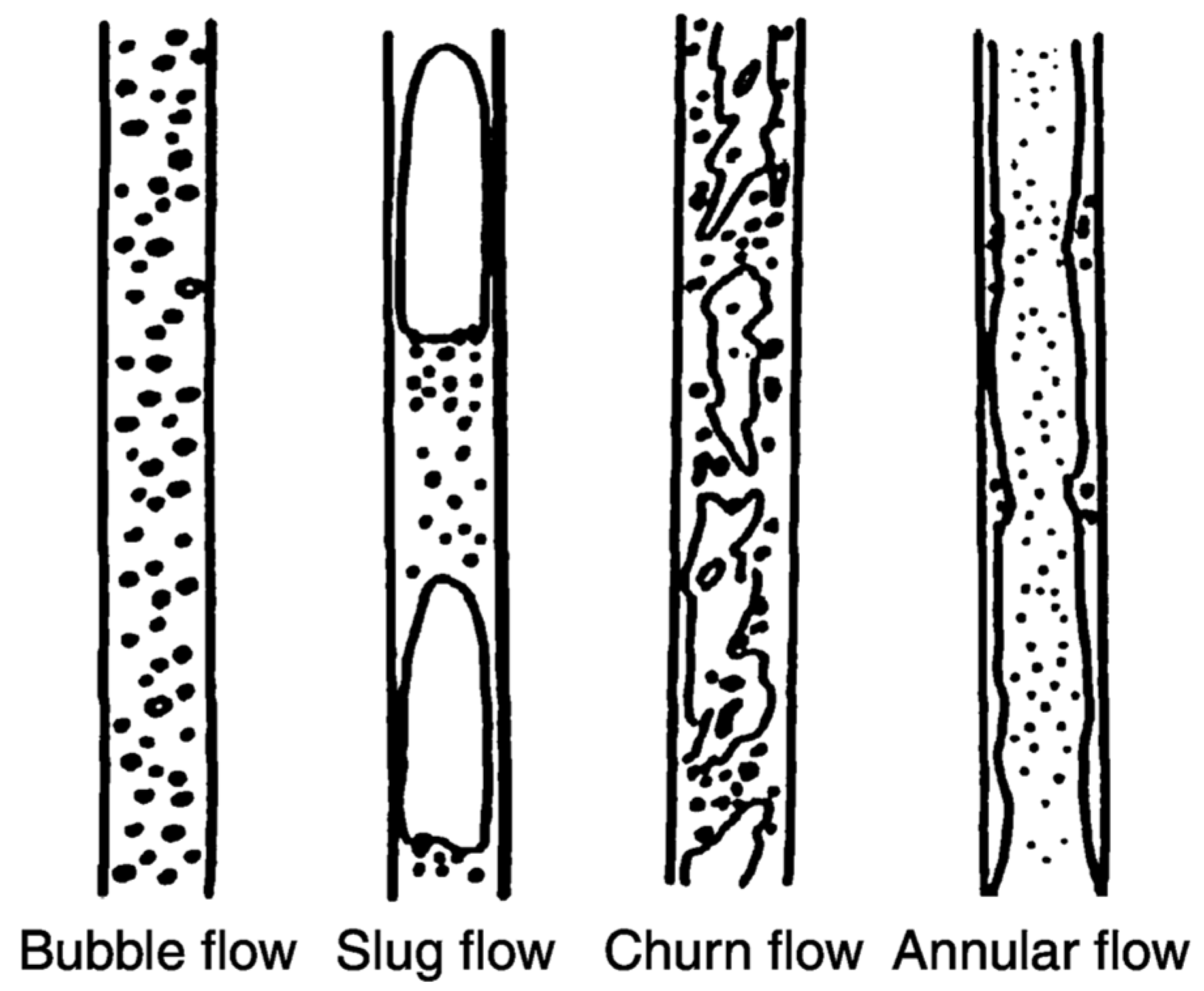
3. Flow in Microchannel Reactors

The flow pattern within a microchannel reactor determines the mixing of reactants and is crucial in quantifying their rate of heat and mass transfer. Hence, this section reviews the types of flow within microchannel reactors, focusing on slug flow pattern, its formation and mass transfer. Slug flow within microchannel reactors occurs due to the difference in density, viscosity and immiscibility between two fluids. As such, liquids and gases are two fluids with the aforementioned differences. The formation of slug flow pattern, the mixing between two fluids and the mass transfer between them is easily explained via liquid and gas slugs in the sections below, due to the distinctively divergent properties between both species. Similarly, biodiesel production through the transesterification reaction involves alternating slug flow of oil and alcohol. Although oil and alcohol form a liquid–liquid flow pattern, both these species are two dissimilar fluids which are immiscible in one another and have different densities and viscosities.

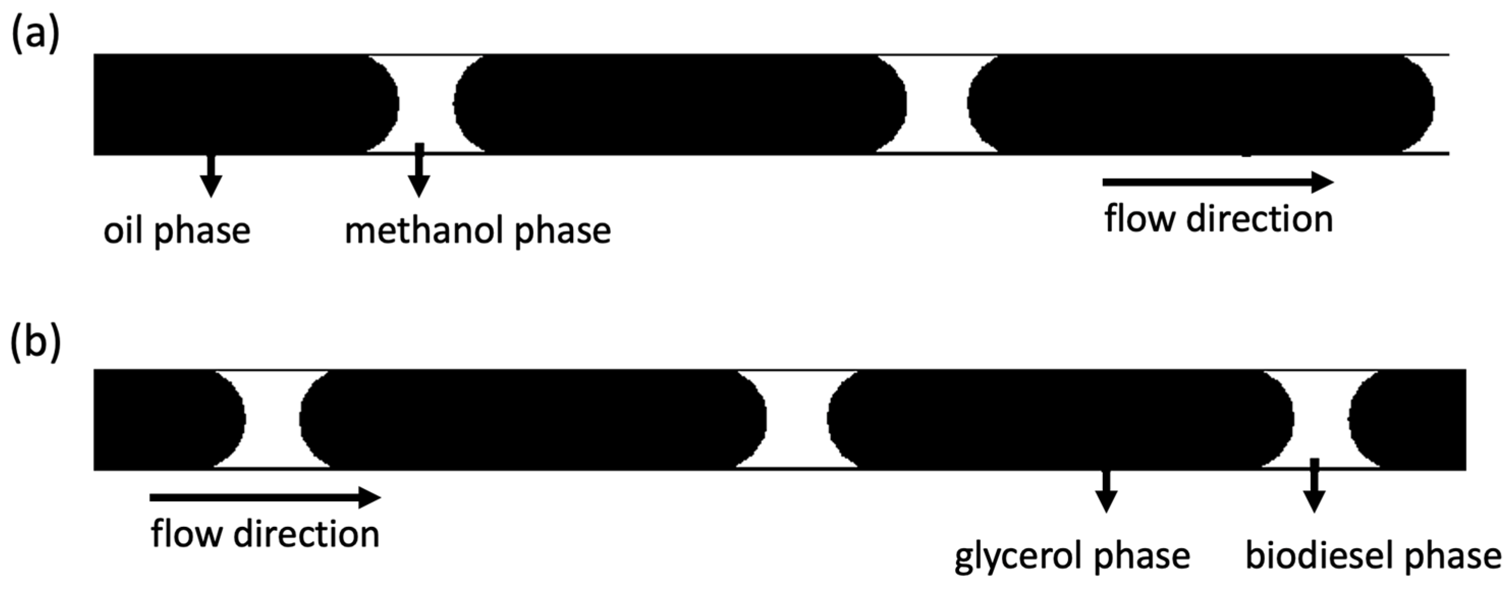
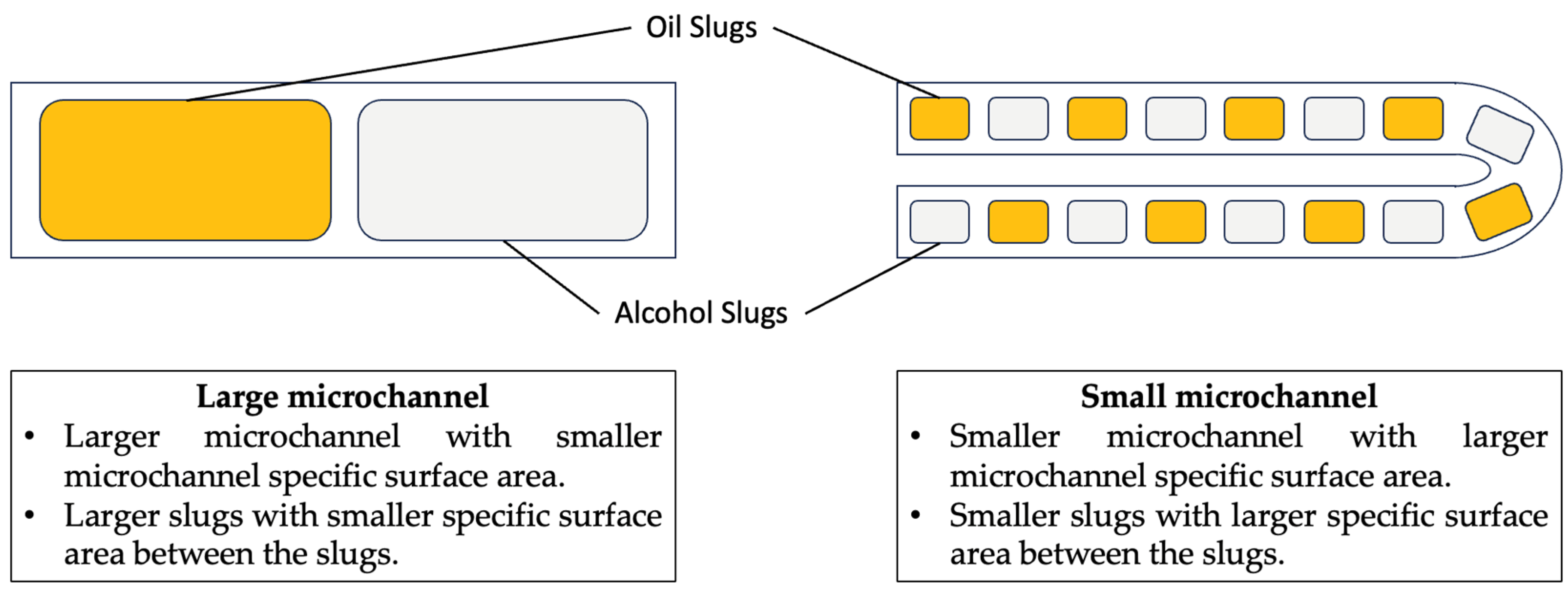
3.1. Slug Flow in a Microchannel Biodiesel Reactor

There are various benefits of slug flow patterns in microchannel reactors. These advantages include reduced reaction time and elevated heat and mass transfer rates [72]. These advantages are achieved, as gas slugs in between liquid slugs significantly improve the mixing of reactants due to internal mixing induced by recirculating flow in between the slugs [73,74]. In the case of biodiesel production, the incorporation of a two-phase liquid–liquid slug flow between triglycerides and alcohol could improve the heat and mass transfer in the transesterification reaction. Existing work on slug flow for the transesterification reaction includes a study by Laziz et al. [75] to produce biodiesel in a T-junction microchannel reactor with a droplet slug flow. The study resulted in a 98% biodiesel conversion in a reaction time of 80 s at room temperature, 25 °C. The methanol-to-oil molar ratio was found to impact the study, where the molar ratio was directly proportional to the biodiesel conversion. The high biodiesel conversion was the result of the higher molar ratio affecting the hydrodynamics of flow, creating a higher number of slugs and a greater interfacial area (surface to volume).
López-Guajardo et al. [76] reported biodiesel production in a tubular microchannel reactor using sunflower oil. A 99% biodiesel conversion was obtained at a 6:1 alcohol-to-oil molar ratio and a 0.7 wt.% catalyst concentration. The reported reaction time was 4 min, which was 15 times faster than conventional batch reactors. Simulation of computational fluid dynamics revealed that the high biodiesel conversion at a fast reaction time was due to an internal mixing effect via slug flow that intensified the mass transfer between reactants.
Sun et al. [77] reported an investigation on slug flow pattern for biodiesel production from cotton seed oil with a 6:1 methanol-to-oil molar ratio, 1% potassium hydroxide catalyst loading and reaction time of 6 min. The study was carried out in a stainless-steel microchannel reactor with a diameter and length of 0.25 mm and 30 m, respectively. Figure 12 illustrates the scheme of (a) reactants and (b) products in the slug flow. The immiscibility of oil, alcohol, biodiesel and glycerol that was caused by high interfacial forces between the fluids resulted in the formation of alternating slugs in the microchannel. Biodiesel yield increased from 96.2% to 99.4% with the increase in reaction temperature from 30 °C to 60 °C with a slug flow pattern. However, further increasing the reaction temperature to 70 °C resulted in a slight drop in yield to 99.1%, with a change in flow pattern from slug to bubble flow due to the boiling of methanol. Furthermore, the specific surface area of microchannels was 2000 m2m−3, 7547 m2m−3 and 16,000 m2m−3 with diameters of 2.0 mm, 0.53 mm and 0.25 mm, respectively. As illustrated in Figure 13, a larger microchannel specific surface area is a result of smaller microchannels, simultaneously creating smaller slugs. Moreover, smaller slugs result in a larger specific surface area between the slugs. The large specific surface area of both microchannels and slugs enhances heat and mass transfer between oil and alcohol, hence contributing to high biodiesel yield.
The surface area of microchannel reactors is anywhere between ten and one hundred times that of conventional reactors, depending on the channel dimensions. Hence, a slight alteration in the flow pattern of microchannel reactors greatly affects the reaction parameters such as temperature, pressure and reactant concentration. This is because the diffusion distance is lower and the interfacial area in the microchannel is higher compared to conventional reactors [47]. Therefore, flow patterns such as slug flow, with properties such as slug formation and slug distance, are important in quantifying mass and heat transfer [78].

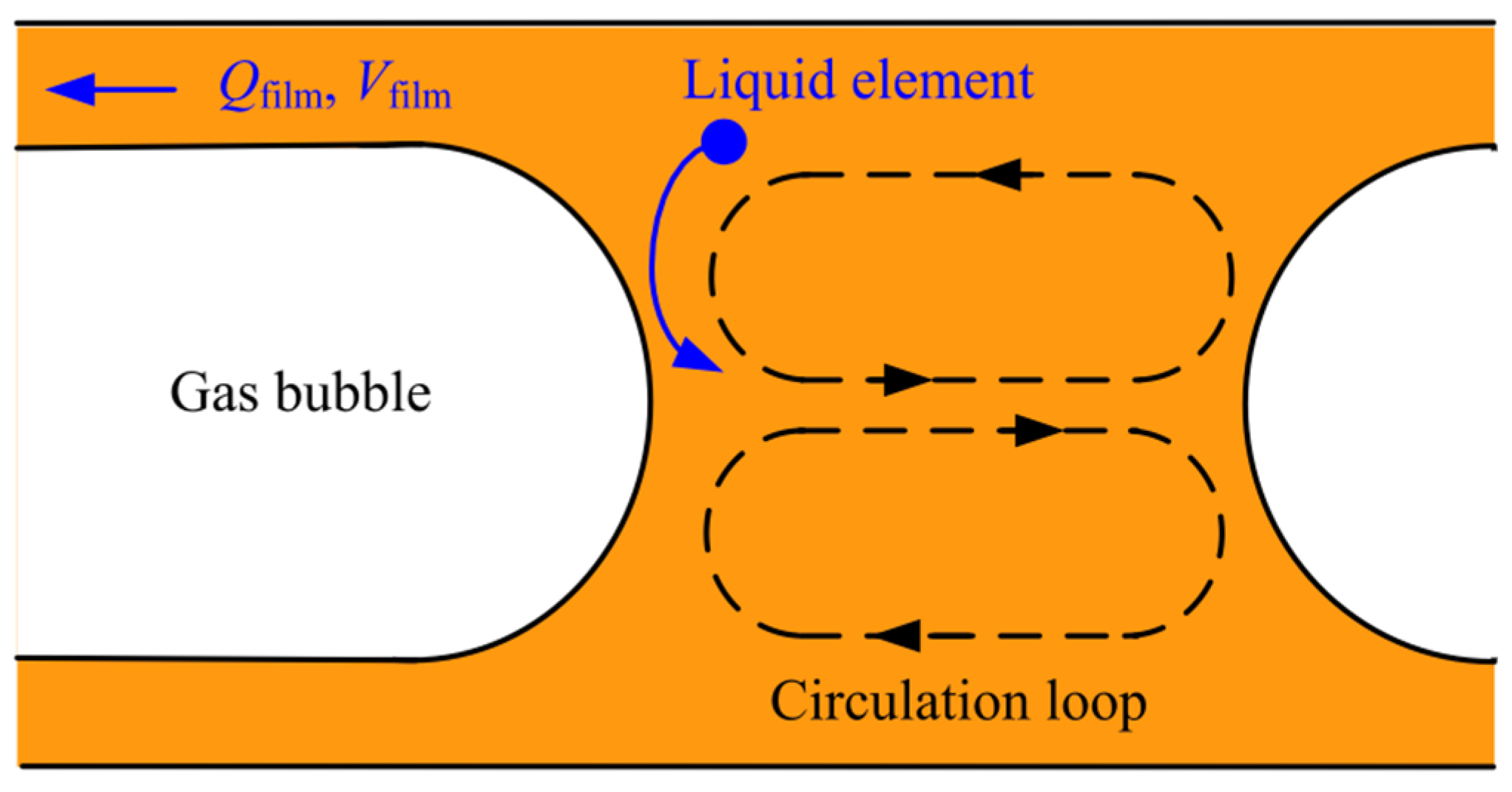
3.2. Slug Flow Formation

The flows inside microchannel reactors follow various patterns. Common internal flow patterns in microchannel reactors are bubble flow, slug flow, churn flow and annular flow as observed in Figure 14. Other flow patterns include stratified flow and droplet flow. Comparatively, slug flow is known to be a complex flow pattern that has unstable flow properties [79]. Slug flow has a two-phase flow pattern of gas slug and liquid slug in an alternating order [80]. Usually, the gas slug comprises a gas bubble, which is surrounded by the liquid film, as illustrated in Figure 15. The gas slug may also appear as two bubbles that separate a liquid slug. Since gas is lighter than liquid, a thin liquid film would exist between the microchannel wall and the gas slug [73]. The wettability of the channel wall and the liquid determines the degree of liquid film formation [72].
The formation of slug flow (long slugs) occurs at a low-to-intermediate volumetric flow rate of gas and liquid, when the interfacial tension surpasses the inertia force of the flow [72,79]. However, gas and liquid slugs in an alternating order (small slugs) occur when the inertial forces of flow increase with flow rate while reducing the interfacial forces. As a result, small spherical-like slugs are formed in an alternating order, as the flow shear stress acts to reduce the growth of slug formation [74]. Maintaining stable slug flow in microreactors throughout the reaction is currently possible due to advancements in the research of microchannel flow patterns. Slug flow could be induced into microchannels by the injection of gas bubbles into a liquid flow at a stipulated pace [73]. This alters the flow dynamics from a single-phase liquid flow to a slug flow. A steady slug flow could be sustained by maintaining constant operational parameters such as the flow rates of liquid and gas, the physical properties of liquid and the dimension of the microchannels [72].
Two-phase gas–liquid slug flow reactions are widely applied for both microscale and industrial-scale chemical reactions. Slug flow utilisation in microscale industrial applications includes pharmaceutical drug production, synthesis of nano particles and heat dissipation for electronic components [78]. Other chemical applications include nitrification, polymerisation, crystallisation, membrane separation, distillation and purification of end products [72,83]. On the other hand, heavy industry application of slug flow mainly occurs in the energy sector. In the petrochemical industry, slug flow benefits oil and gas production and transportation, where mixing and mass transfer in pipelines are crucial [79]. Moreover, slug flow is used in nuclear power plants for reactor cooling and for the generation of steam in the power plant [79]. Slug flow improves heat transfer for these applications.

3.3. Mass Transfer of Slug Flow

Mass transfer of slug flow patterns in microchannels is affected by a few conditions such as microchannel dimension, size or length of gas and liquid slugs, liquid film thickness and the volumetric flow rate through the microchannel. The effect of microchannel dimensions on the mass transfer of slug flow was reported by Singh et al. [84] by quantifying the mass transfer coefficient. The manipulated parameter for this study was the diameter of microchannel capillaries. It was found that mass transfer was higher with smaller microchannel dimensions since smaller microchannel capillary diameters result in higher mass transfer coefficients.
As illustrated in Figure 15, a liquid film is formed between the wall of the microchannel and the gas slug. Efficient mass transfer that is significantly higher than other parts of the flow occurs at the liquid film segment, as this segment has the highest specific surface area for mixing [83]. The size and dimensions of gas slugs can be well controlled with precise microchannel manufacturing methods [83]. Thus, short liquid slugs can be induced by introducing long gas slugs in between to divide the liquid. Therefore, the long gas slug creates a long liquid film between the wall of the microchannel and the gas slug. High mass transfer is achieved at these liquid film zones induced by the consecutive long gas slugs, which increases the specific surface area for mixing. Moreover, the thickness of the liquid film formed is another crucial parameter of slug flow patterns. The liquid film thickness has a direct effect on the heat and mass transfer properties of reactants in the microchannel. Hence, knowing or predicting the liquid film thickness would benefit reactive flow studies that intend to quantify mass transfer rates of slug flow reactions within microchannels [80].
Santiago et al. [74] reported a correlation between volumetric flow rate and mass transfer for slug flow in microchannels. The specific interfacial area within the microchannel was measured via image processing and was used as the responding variable. The specific interfacial area reportedly increased constantly as the volumetric flow rate increased. This happened because the slug size in the microchannel was reduced at higher volumetric flow rates due to the inertial forces and shear forces. The smaller slug size resulted in an increase in specific interfacial area. This phenomenon increased the mass transfer for the reactants. The mass transfer was quantified via overall volumetric mass transfer coefficients, where the higher the volumetric flow rate, the higher the mass transfer coefficient values. This is because the increased specific interfacial area decreases the mass transfer resistance. Therefore, increasing the volumetric flow rate enables higher mass transfer of reactants for slug flow patterns in microchannels.
Nie et al. [85] elaborated on the occurrence of mass transfer in a microchannel with slug flow. In a microchannel, there are often changes in channel dimension to induce mixing. These changes are in the reactant inlet segment, curves or bends of the channel pathway and are intentional obstacles to the channel’s internal geometry. Reactants that flow through a narrower part of the channel would accelerate due to the instantaneous shrinkage of the channel’s cross-sectional dimension. As a result of the acceleration, reactants inside the microchannel experience a drop in pressure. Once past the channel’s narrow segment, the channel is widened to its original dimension, hence slowing the flow of reactants. However, kinetic energy is generated during acceleration of the flow at the narrow segment. Kinetic energy is transformed into pressure, thus increasing and normalising the internal flow pressure. Frictional resistance in the flow is also overcome by the kinetic energy generated.
Once all the kinetic energy has been exhausted, the flow velocity eventually attains a stagnation point, where the local velocity of the reactants is zero [85]. The flow of reactants reduces while pressure continues to increase when the reactants flow beyond the stagnation point. As a result, backflow would occur due to the effect of pressure and inertia. The flow pattern would then be disturbed as backflow causes the flow to collide with the reactants at the back, thus promoting better mixing. Hence, mass transfer is intensified, as better mixing is achieved in microchannels between the liquid slug and liquid film.
Slug flow promotes mixing in an efficient way by creating recirculation zones. In a slug flow pattern, interfacial forces acting over inertial forces cause liquid and gas slugs to be arranged in an alternating manner throughout the microchannel. This results in the occurrence of internal circulation zones between the slugs. The internal circulation is caused by the tension between the slug interface and microchannel walls [74]. Recirculation zones are often formed at the flow’s stagnation point and induce mass transfer through convection.
Furthermore, a smaller slug size enables superior heat and mass transfer properties via recirculation zones, in comparison with slug flow with bigger slug formation. A smaller slug size creates more recirculating zones throughout the flow. Simultaneously, frequent interruption of the boundary layer takes place, both of which result in superior mass transfer and better mixing [73]. The mixing of liquid elements via the recirculation zones to enhance mass transfer in slug flow is illustrated in Figure 16.
A study by Zhang et al. [86] reports the mass transfer properties of slug flow of an immiscible liquid–liquid system using ethyl acetate and water in a circular polytetrafluoroethylene (PTFE) microchannel. The dispersion of alternating slug formation, its size and stability were determined by the flow interfacial tension, which overpowers the flow viscosity and inertia. It was found that both the volumetric mass transfer coefficient (kLa) and the mass transfer coefficient (kL) were affected by flow rate, where the mass transfer coefficients were reported to increase with the reactant flow rate. The kLa range was reported to be between 0.03 and 0.3 s−1 m/s, whereas kL was found to be between 2 × 10⁻⁵ and 7 × 10⁻⁵ m/s. The microchannel dimensions studied were 0.8 mm, 1.2 mm and 1.8 mm. The smaller the microchannel dimensions, the higher the mass transfer coefficients. This was because smaller microchannel dimensions enabled better mass transfer due to the larger surface area of slugs. Furthermore, both kLa and kL increased with an increase in temperature. Higher temperature led to higher mass transfer due to better diffusion coefficients.
Ramji et al. [87] developed a model mass transfer featuring a liquid–liquid slug flow system in a microchannel. Using the model, the mass transfer rate was related to the Peclet number (Pe), flow viscosity and slug liquid film. The mass transfer increased with an increase in Peclet number, while other flow conditions such as slug holdup and aspect ratio were kept constant. The effect of Pe on mass transfer was investigated by examining five Pe values ranging from 1 to 10,000. Pe = 1 denoted slug mixing as diffusion, while a transmission phase was denoted at Pe = 100 where diffusion and convection patterns took place at the same time. At Pe = 1000, the slug mixing was predominantly convection, whereas the convection pattern stabilised at a uniform equilibrium point at Pe = 10,000. The higher the Peclet number, the greater the mass transfer coefficient. The mass transfer coefficient was about 40 at Pe = 1 and increased to about 118 at Pe = 5000. The increase in the mass transfer rate of reactants with Pe in a slug flow pattern was evidently enhanced via convection mixing.
Furthermore, the study reported that a more viscous flow through the microchannel resulted in a higher mass transfer. Reactants of higher viscosity enabled slugs of smaller length to be formed. Additionally, smaller slug formation enables a higher slug quantity to be formed in the microchannel. The interfacial area in between each slug was higher with smaller slug formation, thus promoting better mass transfer. Also reported in the study was the effect of liquid film (the thin film that is formed between the slug and the microchannel wall) on the mass transfer. The presence of the liquid film enhanced mass transfer, as the rate of mass transfer was lower in the case study without the presence of liquid film. In addition, the size of the liquid film positively affected the mass transfer rate, where the thicker the liquid film, the higher the mass transfer. The thickness of the liquid film was attributed to a higher interfacial area between the slug and microchannel wall for mixing to occur, thus promoting greater mass transfer.
Xu et al. [88] reported a liquid–liquid two-phase slug flow experimental investigation on mass transfer in a microchannel. The study adopted Danckwerts’ model to distinguish the volumetric mass transfer coefficient at various experimental operating parameters. Slug formation in microchannels was driven by the interfacial force of the flow that dominated shear stress. The size of slugs was found to be influenced by flow velocity. The slug size was inversely proportional to the flow velocity. However, the velocity of the formed slug heavily influenced the volumetric mass transfer coefficients in the microchannel. The volumetric mass transfer was denoted as the function of slug velocity, where the higher the slug velocity, the higher the mass transfer rate. This was because an increased slug velocity induced an increase in the severity of flow internal recirculation within the slug. Also, the shear force between the slug and the microchannel wall increased. As a result of better internal recirculation, the slug boundary layer thickness was reduced. This promoted better mixing of reactants, thereby enhancing the mass transfer of reactants.
Furthermore, the dimension of microchannel capillaries also affected the volumetric mass transfer coefficient. Capillary diameters were manipulated to investigate their effect on mass transfer. Capillary sizes of 0.6 mm and 0.8 mm were utilised in the experiment while maintaining slug velocity as constant. The volumetric mass transfer coefficient increased with a reduction in the capillary diameter. This was due to the increase in interfacial area, caused by the decrease in the microchannel capillary diameter. The interfacial area of 0.6 mm and 0.8 mm capillary diameters was about 40,000 m2/m3 and 3000 m2/m3, respectively. Higher interfacial area promoted better mixing, hence resulting in a higher volumetric mass transfer coefficient.
This subsection provided critical information on maximising the yield of chemical reactions in microchannel reactors by enhancing mass transfer between reactants. Key considerations include the size of microchannel reactors, especially the internal diameter, which determines the formation of slug flow, and the interfacial area of slugs within the microchannel and between individual slugs. Additionally, the shape of the micromixer’s geometric obstacles, the volumetric flow rate and the viscosity of reactants determine the degree of mixing via internal recirculation zones and affect slug properties such as size and length. Thus, to enhance the mass transfer of reactants in a microchannel reactor, it is crucial to optimise all these considerations, as the aforementioned factors dictate the effectiveness of mass transfer.

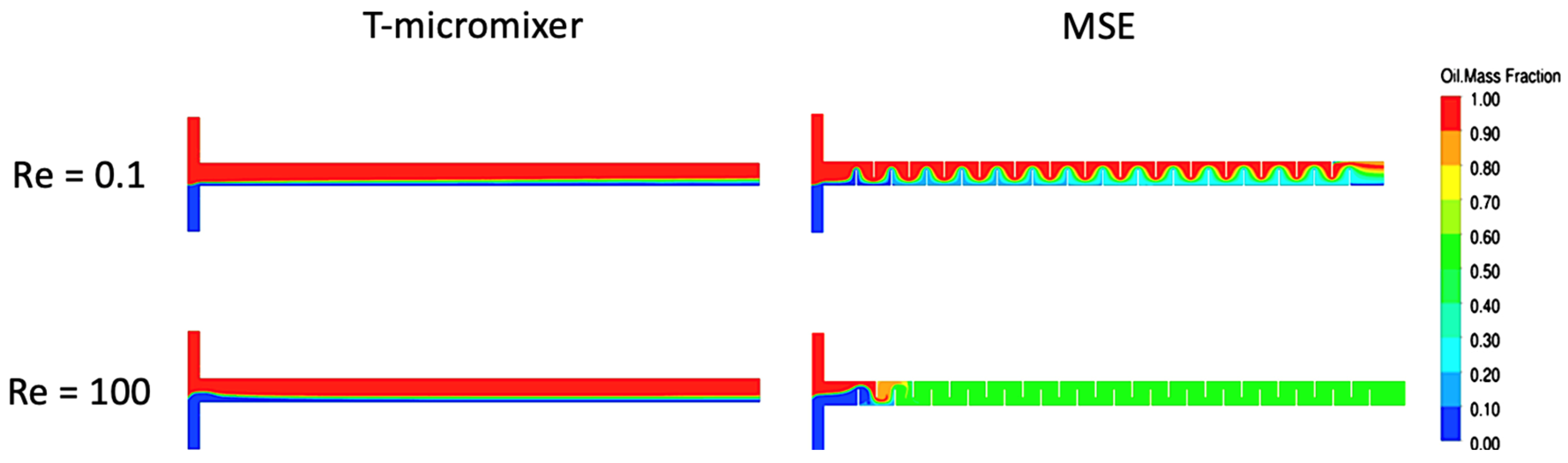
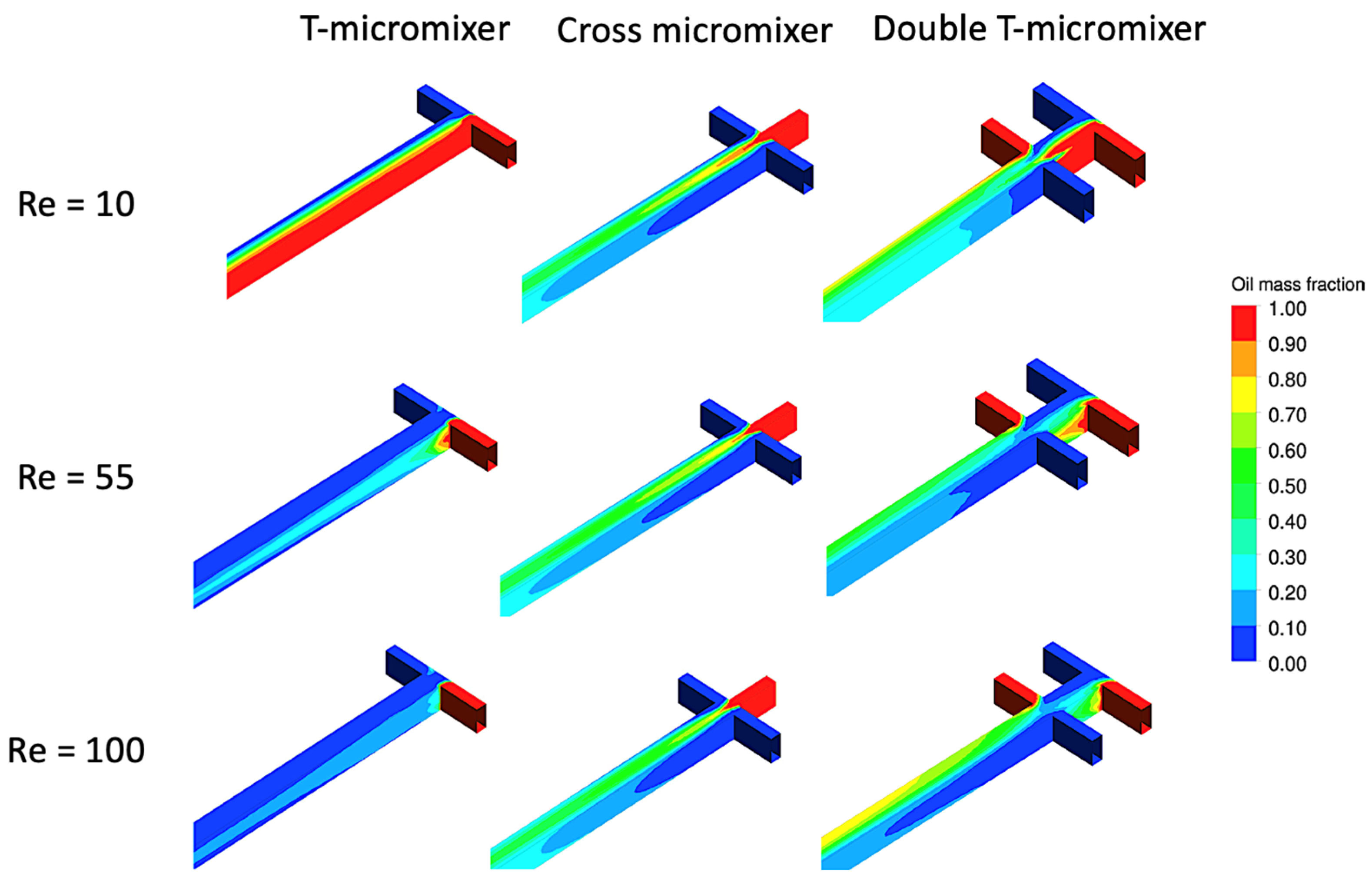
4. Simulation Studies in Microchannel Reactors

Computational fluid dynamics (CFD) is within the domain of fluid mechanics, which solves fluid flow problems by applying computational tools [89]. CFD cases are simulated using partial differential equations to represent two-dimensional or three-dimensional flow. CAD software would first be used to generate the physical model of the flow geometry, and thereafter, a mathematical model would be used for the representation of fluid flow parameters. Conservation laws are utilised to control volume; hence, the flow is described by dependent field variables. The field variables in the partial differential equations include velocity and pressure, whereas time and domain dimensions are examples of independent variables. This section discusses the simulation studies that have been conducted to investigate fluid flow within microchannel reactors. As such, Table 3 summarises the CFD simulation studies in microchannel reactors for biochemical processes, such as biodiesel production.
Laziz et al. [1] utilised 3D CFD simulation to study the flow of biodiesel production in a microchannel. A T-junction microchannel was used in this investigation for the transesterification of vegetable oil and methanol with a KOH catalyst. Both experimental and numerical studies were performed using a transparent capillary microchannel with a length and inner diameter of 1 m and 690 μm, respectively. The simulations were solved using volume fractions in each phase, and surface tension was determined via continuous surface force. The results indicated that a 98.6% biodiesel conversion was achieved. However, a high 5% catalyst concentration was required. Additionally, the beginning stages of the flow indicated that there were no mass transfer limitations in relation to residence time. Furthermore, simulation results indicated a torus-shaped recirculation zone in between the slugs, as shown in Figure 17. The recirculation zone promoted enhanced mixing that improved the mass transfer of oil and methanol for biodiesel conversion.
Santana et al. [90] reported the investigation of biodiesel production using sunflower oil with ethanol in microchannel reactors. The effectiveness of a micromixer with static elements (MSE) was evaluated against a T-micromixer (micromixer without static elements). The biodiesel reaction conditions investigated were reaction temperature (25–75 °C), inlet velocity of oil (6.66, 7.40, 8.88 m/s), inlet velocity of ethanol (5.18, 4.44, 2.96 m/s) and alcohol-to-oil molar ratio (6:1, 9:1, 12:1). Fluid mixing was studied with Reynolds numbers of 0.1 to 100. The kinetic model used for the simulation was adopted by Tapanes et al. [94] and Freedman et al. [95]. The results revealed that numerically, the MSE micromixer had a biodiesel conversion of 91.53% at a reaction temperature, alcohol-to-oil molar ratio and catalyst concentration of 75 °C, 9:1 and 1%, respectively. Also, the highest mixing was achieved at a Reynolds number of 100, as observed in Figure 18. Experimentally, the MSE micromixer produced the highest biodiesel percentage of 99.53% at a reaction temperature, alcohol-to-oil molar ratio and catalyst concentration of 50 °C, 9:1 and 1%, respectively. The biodiesel conversion had an 8% difference between the simulation and experiment results.
In another study, Santana et al. [91] investigated the flow simulation of the transesterification reaction for Jatropha curcas oil and ethanol in a microchannel reactor with single-phase turbulence. The kinetic model adopted for this study was proposed by Tapanes et al. [94] and Freedman et al. [95]. Three designs of microreactor were investigated, namely the double-T-shaped, T-shaped and cross-shaped microreactors. The mixing index was used to determine the efficiency of the micromixer designs and was calculated by biodiesel conversion and the variation in the mass fraction. On the other hand, Reynolds numbers ranging between 10 and 100 were used to evaluate the mixing of fluid. The results indicated the highest oil conversions of 98.48%, 98.55% and 96.00% in the T-micromixer, cross-shaped micromixer and double-T-micromixer, respectively. Furthermore, the mixing effect in the cross-shaped microreactor indicated no fluctuations with the difference in Reynolds number. However, the mixing effect was directly proportional to the Reynolds number in the T-micromixer and inversely proportional in the double-T-micromixer, as shown in Figure 19. However, the increase in residence time improved biodiesel yields across all microreactor designs.
A study on numerical simulation of biodiesel production in microchannels with circular obstructions was reported by Santana et al. [92]. Two microchannel designs with circular obstructions, namely T-channel with circular obstructions and T-channel with alternate circular obstructions, were investigated. A T-channel microchannel was used as a control design for comparative study. The circular obstructions in microchannel reactors split and recombined the flow stream. This induced vortex in between the circular obstacles promoted the mixing of reactants, as shown by the simulation velocity vectors in Figure 20. Reynolds number and residence time were varied from 1 to 160 and 0.20 to 100 s, respectively. The results indicated the highest biodiesel yield and mixing degree of 99.09% and 0.99, respectively, by the T-channel with alternate circular obstructions. Comparatively, the T-channel and the T-channel with circular obstruction microreactors had a biodiesel yield of 99.07% and 99.01%, respectively.

5. Challenges, Limitations and the Future of Microchannel Reactors

As discussed in previous sections, microchannel reactors are advantageous in aspects of energy consumption, time and continuous flow for the production of biodiesel. However, there are certain limitations and drawbacks associated with the usage of microchannel reactors. Table 4 summarises the main challenges of utilising microchannel reactors and the potential solutions that create a pathway towards the future of microchannel reactors.

6. Future Directions

The future direction of biodiesel production requires microchannel reactors to be integrated with a more efficient heating mechanism to limit heat losses and further elevate heat and mass transfer of the reaction. Hence, this section discusses the potential of microwave irradiation heating for biodiesel production and its integration with microchannel reactors.

6.1. Microwave-Assisted Heating

Heat delivery is an important component of temperature-dependent reactive chemistry. The transesterification reaction for the production of biodiesel is an example of a temperature-dependent chemical reaction for the production of biodiesel. Being endothermic in nature, the rise in temperature moves the equilibrium of the transesterification reaction forward towards the product side. Conventional heat delivery in the form of thermal conductive heating is the most common heating mechanism used for biodiesel production. Conductive heating transfers heat energy onto the surface of materials thermodynamically [2]. Heat is delivered to the reactants via surface thermal conduction and convection currents. Heat delivery to reactants via conduction involves the heating of mediums such as the reaction vessel, hot plate surface and oil bath, as heat flows from an externally hot area to a cooler area inside the reactor [105]. The energy required depends on the properties of the mediums heated such as thermal conductivity, density and specific heat. Therefore, this process expedites energy loss to the surroundings and requires a large amount of energy to deliver heat to reactants [2]. Thus, the conventional heat delivery method for biodiesel production has various limitations, such as low efficiency, requiring long reaction time and high energy demand [106].
In recent years, the microwave heating mechanism has gained popularity as a choice of heat delivery for biochemical processes such as the transesterification reaction [107]. Studies have reported that microwave-assisted transesterification has improved the efficiency of biodiesel production compared to conventional thermal conductive heating in various ways. Microwave irradiation eliminates heat loss to the environment and material surfaces. This enables the availability of sufficient activation energy through lower energy consumption [108], thus making biodiesel production an energy- and cost-effective process [2]. Microwaves deliver heat directly to the reactants [109], with the pathway direction being from the inside to outside, as observed in Figure 21. Thus, in contrast to conductive heating, microwave irradiation enables transesterification to begin much earlier [110] while accelerating the rate of reaction [111] with substantially lower energy consumption [112]. Moreover, microwave heating enables short reaction times via rapid heating [105], improves the quality [113] and yield [17] of the biodiesel produced, and enhances the separation of glycerol (a by-product of the transesterification reaction) [110].
Microwaves are a type of electromagnetic radiation that is generated by the magnetron in a microwave using electricity. Microwave heating is efficient due to its ability to deliver localised superheating directly to the reactants at a molecular level [112]. Since microwave heating occurs via the phenomenon of dipolar polarisation, reactants with polar molecules are favoured, where microwaves cause resonation of the polar molecules, resulting in their temperature increase [17]. In biodiesel production, the reactants mainly consist of triglycerides and alcohol. Predominantly, triglycerides do not respond to microwave irradiation as they are non-polar molecules. However, methanol (a common choice of alcohol for biodiesel production) can be heated via microwaves because its molecules have ionic components and -OH groups, which are polar molecules that are dipole sensitive [114] and have high dielectric loss [115]. Energy is transferred to the methanol’s polar molecules by microwaves, where energy is absorbed due to their dipolar rotational force and ionic conduction [116], as observed in Figure 22. Dipolar polarisation induces the vibration of methanol dipoles and causes them to continuously spin and realign based on the constant oscillation of microwaves [115], thus resulting in localised superheating due to the vibration of methanol molecules. Furthermore, microwave irradiation causes the methanol ions to oscillate back and forth [105], hence generating heat through the friction of ions colliding with one another and their molecular rotational force while spinning [116].
The literature has reported that the formation of transesterification by-products is slow at lower microwave irradiation levels [112]. High microwave irradiation could damage the molecular structure of triglycerides, promoting degradation into free fatty acids, which react with the base catalyst used for transesterification to form soap via the saponification reaction. The degradation of triglycerides into undesired by-products before the reaction would certainly reduce the biodiesel yield [101]. On the other hand, higher microwave power output results in a higher reaction temperature for transesterification. This is because higher reaction temperature promotes a higher rate of transesterification, until the equilibrium phase is attained. Thus, controlling and optimising microwave power output is vital during the usage of microwave heating for biodiesel production, as transesterification is a temperature-sensitive reaction.

6.2. Microwave-Assisted Transesterification for Biodiesel Production

Biodiesel production through microwave-assisted heating has been investigated by researchers due to its many advantages. From the previous subsection, microwave heating is understood to enable localised superheating directly to the reactants through ionic conduction and dipolar polarisation. This increases the rate of transesterification and simultaneously limits heat losses through conduction. This section discusses the utilisation of microwave irradiation for biodiesel production, as it is viewed to possess great potential to be used alongside microchannel reactors in the near future. Table 5 summarises reviews of microwave-assisted transesterification for biodiesel production from the years 2020 to 2023.
Yang et al. [118] recently investigated the potential of microwave-assisted biodiesel production using waste cooking oil and soybean oil as feedstocks. The transesterification reaction was carried out using a 30 mL glass vial in the microwave reactor while maintaining a temperature of 80 °C with an oil-to-methanol molar ratio of 1:11. The highest biodiesel yield was 99.5%, with soybean oil as feedstock. Microwave-assisted heating reportedly enabled rapid soybean biodiesel production with a reaction time of 5 min, in comparison with 20 min via the conventional heating method.
Prajapati et al. [119] studied biodiesel production using microwave irradiation as a heat source for the transesterification of waste cotton seed cooking oil, in the presence of a calcium oxide base catalyst. Response surface methodology (RSM)-based Central Composite Design (CCD) was applied for this study. A 99.83% biodiesel yield was achieved under optimised reaction conditions of a 1:9.63 oil-to-methanol ratio and 1.34 wt.% catalyst loading at 9.87 min of reaction time in a batch reaction process. The reaction temperature was maintained at 50 °C at a microwave power of 180 W. This indicated that increased contact between reactants was achieved with extended periods of microwave irradiation exposure.
Ergan et al. [121] studied microwave-assisted biodiesel production using canola oil in comparison with conventional heating. All reaction conditions were kept constant for both heating methods, which were catalyst loading, oil-to-methanol molar ratio, reaction time, temperature and microwave power of 5 wt.%, 1:9, 120 min, 65 °C, and 48 W, respectively. The microwave-assisted biodiesel production had a conversion of 99.1%, which was 30.2% higher than that of conventional heating. Besides the high biodiesel yield, time- and cost-effective biodiesel was achieved through the microwave-assisted system. The effect of microwaves on the catalyst was believed to have contributed to the higher biodiesel conversion by increasing the local surface temperature through the vibration of dipoles.
Gouda et al. [106] converted oleic acid into methyl oleate via a microwave-assisted transesterification reaction at 50 W of microwave power. A biodiesel yield of 98.3% was obtained at reaction conditions of a 1:20 oil-to-methanol molar ratio, 1 h reaction time and 100 °C reaction temperature. In comparison with the convectional process, microwave irradiation in combination with the catalyst utilised reportedly increased the rate of the transesterification reaction, resulting in rapid biodiesel production.
Pham et al. [122] utilised waste catfish oil as feedstock for biodiesel production with microwave irradiation heating. In this investigation, the effect of two co-solvents was studied (acetone and isopropanol), which served to dissolve the catfish oil and methanol for better diffusion. Furthermore, second-order polynomial regression models were used in this study to predict the biodiesel yield. The highest predicted yield and actual yield were 99.0% and 98.9%, respectively, using acetone as a co-solvent. The reaction temperature, microwave power, reaction time and catalyst loading were 53.2 °C, 300 W, 94.4 s and 1 wt.% of potassium hydroxide, respectively. The usage of microwave-assisted heating reportedly led to a rapid transesterification reaction with an increased biodiesel yield.
Nazir et al. [123] reported the conversion of waste cooking oil into biodiesel using sugarcane bagasse biochar as a catalyst. Microwave irradiation was used to maintain the reaction temperature at 60 °C. The highest biodiesel yield of 92.12% was obtained within 15 min using 5 wt.% of catalyst loading at a 1:15 oil-to-methanol molar ratio. The influence of microwave heating was highlighted as being energy and cost efficient, since the reaction time of biodiesel production was significantly reduced when compared against 2.5 to 5 h for conventionally heated transesterification.
In another study, Zhang et al. [124] reported a 95.0% biodiesel conversion from chicken feather meal oil using 1 wt.% of a chicken eggshell-derived calcium oxide catalyst. The transesterification reaction was carried out inside a microwave reactor, with 500 W of microwave irradiation serving as the heat source. In the study, the microwave power was varied between 200 W and 800 W; however, increasing the power beyond 500 W negatively impacted the biodiesel yield. Accelerated and efficient biodiesel production was made possible by microwave heating through limiting heat losses throughout the reaction. The biodiesel produced had a high heating value and flash point of 50 MJ/kg and 153 °C, respectively. Also, the biodiesel was of low viscosity at 4.15 mm2/s and had a cetane number and pour point of 50 and 12 °C, respectively.
Ali et al. [131] reported the usage of a custom-built microwave-assisted reactor for the transesterification of waste cooking oil into biodiesel as shown in Figure 23. An activated limestone-based catalyst was deployed for the reaction while maintaining conditions such as reaction temperature and oil-to-methanol molar ratio at 65 °C and 1:12.21, respectively. A biodiesel yield of 96.65% was achieved at 55.26 min of reaction time. In comparison with conventionally heated water bath transesterification that produced a lower yield of 77.5%, the microwave-assisted reaction was proven to be superior by channelling direct heat to the reactants.
Binnal et al. [126] reported the conversion of dairy scum oil to biodiesel via microwave-assisted heating in a two-step esterification and transesterification reaction. Due to its high acid value, dairy scum oil was esterified in the presence of sulphuric acid to reduce its free fatty acid content. The transesterification reaction was then carried out at 600 W microwave power, maintaining a reaction temperature of 60 °C, and catalysed by 1 wt.% potassium hydroxide. A biodiesel yield of 93.47% was obtained in 5 min of reaction time. Using microwave-assisted heating, the activation energy (Ea) of 9.87 kJ/mol and the rate constant (kT) of 0.574 min−1 were found to be lower and higher, respectively, in comparison with those of an electrically heated transesterification reaction.
Hsiao et al. [127] investigated the effect of microwave heating on the transesterification of waste cooking oil in contrast to conventional heating via a water bath. Microwave irradiation significantly improved the reaction time of the transesterification reaction, as biodiesel conversion was 98.2% at 75 min via microwave-assisted heating, Comparatively, conventional heating required 140 min to achieve the same biodiesel conversion. All other reaction parameters were kept constant at an oil-to-methanol molar ratio, reaction temperature and catalyst loading of 1:8, 65 °C and 4 wt.% calcium oxide, respectively. It is worth noting that microwave-assisted heating was found to enhance the efficiency of the transesterification reaction by escalating the heat transfer between reactants.
Similarly, Athar et al. [128] studied the effect of microwave irradiation heating in comparison to conventional heating for biodiesel production, using 4-dodecylbenzenesulfonic acid as a catalyst. Sunflower oil was used as feedstock with a reaction temperature and oil-to-methanol molar ratio optimised at 76 °C and 1:9, respectively. Under these reaction conditions, a biodiesel yield close to 100.0% was achieved in 30 min with 300 W microwave-assisted heating, in contrast to 6 h with conventional heating. This was due to microwave heating enhancing the rate of the transesterification reaction. Direct absorption of microwave irradiation by the OH group caused a localised increase in temperature and provided activation energy for transesterification in abundance, thus increasing the rate of reaction. Also, the reorientation of methanol dipoles when subjected to microwave irradiation enhanced the contact between methanol and oil.

6.3. Combined Microchannel Reactor and Microwave Heating

Based on the review of microchannel reactors for liquid reactants, the novel research of utilising microchannel reactors in combination with microwave heating is proposed. At the point of writing this review, no research has reported the usage of a microchannel reactor coupled with microwave irradiation heating to facilitate a reactive flow chemical reaction, such as transesterification to produce biodiesel.
The utilisation of microchannel reactors offers continuous biodiesel production, which provides various advantages compared to batch processing, as summarised in Table 6. Furthermore, microchannel reactors allow for superior mass and heat transfer of reactants, enabling a high yield of products and a fast reaction time of below 1 min [133]. This is possible by taking advantage of the small dimensions of microchannel capillaries (0.01 mm to 1 mm), where the effect of reaction parameters such as temperature, chemical loading, mixing and time are multiplied by anywhere from ten to a hundred times (depending on microchannel capillary dimension) in contrast to conventional reactors. Furthermore, small microchannel capillary dimensions enable the formation of flow patterns such as slug flow, which further enhances the mass and heat transfer of reactants through internal circulation zones in between slugs.
On the other hand, the introduction of microwave heating to reactions in microchannel reactors is predicted to further enhance the reaction efficiency in terms of energy utilisation and conservation, cost and time as reported by researchers [134]. Microwave heating offers several benefits compared to conventional surface contact heating via conduction. Microwave irradiation enables non-contact penetrative heating that prevents heat loss to the surroundings and other materials such as hot plates, oil baths, glass appliances, and the surface walls of materials and vessels by conduction and convection. Furthermore, microwave heating transfers energy directly to the molecules of reactants via irradiation. This allows for direct, efficient and rapid heat delivery to reactants. Thus, microwave-assisted heat delivery in combination with microchannel reactors has great potential to create a path towards a green and sustainable biodiesel production method. However, further research is required to improve microwave-assisted heating technology. This is because microwaves, being sinusoidal waves, can create a combination of cold and hot spots upon their emission for heating purposes. The challenges to be overcome include maintaining a homogeneous and stable reaction temperature throughout the medium being heated.

7. Conclusions

Fossil fuels are subjected to depletion and their use is known to cause harmful emissions of greenhouse gases into the environment. Furthermore, in the past two years, the COVID-19 pandemic and the Russia–Ukraine conflict have caused fluctuations in fossil fuel prices. All these factors prompt the development of an alternate source of clean energy that is renewable and sustainable. The development of renewable energy, specifically liquid biofuels such as biodiesel, involves biochemical processes. Microchannel reactors are being increasingly researched and developed for reactive flow chemical processes, due to their ability to achieve high heat and mass transfer in chemical reactions. This results in a rapid reaction time, lower energy consumption and lower chemical production cost. From an environmental perspective, the reduction in time, energy and chemicals utilised for the reactions translates to overall reduced greenhouse gas emissions (carbon dioxide equivalent). In this review, the recent developments in microchannel reactors for biodiesel production, along with the flow of liquid reactants and their mass transfer properties, were discussed. The key to enhanced mass transfer is the design of microchannel reactors and micromixers. An ideal design enables the enhanced mixing of reactants (by disrupting the laminar flow), thus increasing their mass transfer. Additionally, the heat delivery method is crucial for efficient reactions, as it influences the rate of mass transfer. Conventional conductive heating is inefficient as it is prone to heat losses. In contrast, microwave-assisted heating is being increasingly explored for biodiesel production due to the efficient heat delivery of microwave irradiation directly to the reactants through localised superheating. As a result, time-, energy- and cost-effective biodiesel production is achievable while eliminating heat losses. Therefore, the outcome of this review suggests that future research for biodiesel production should utilise microchannel reactors in conjunction with microwave irradiation heat delivery, as this combination has high prospects of facilitating rapid reactions with enhanced mass transfer between reactants.

Author Contributions

Conceptualisation, K.S., J.-H.N., K.Y.W., K.H.W. and C.T.C.; Writing—Original Draft Preparation, K.S. and J.-H.N.; Writing—Review and Editing, K.S., J.-H.N., K.Y.W., K.H.W. and C.T.C.; Visualisation, K.S., J.-H.N. and K.Y.W.; Supervision, J.-H.N., K.Y.W. and K.H.W.; Funding Acquisition, J.-H.N. All authors have read and agreed to the published version of the manuscript.

Funding

This research was funded by the Malaysian Ministry of Higher Education (MOHE) through the Fundamental Research Grant Scheme (FRGS) under grant number FRGS/1/2020/TK0/USMC/02/1.

Acknowledgments

The authors thank the Malaysian Ministry of Higher Education (MOHE) and the University of Southampton Malaysia for the support provided.

Conflicts of Interest

The authors declare no conflicts of interest.

References

  1. Mohd Laziz, A.; KuShaari, K.; Azeem, B.; Yusup, S.; Chin, J.; Denecke, J. Rapid production of biodiesel in a microchannel reactor at room temperature by enhancement of mixing behaviour in methanol phase using volume of fluid model. Chem. Eng. Sci. 2020, 219, 115532. [Google Scholar] [CrossRef]
  2. Bashir, M.A.; Wu, S.; Zhu, J.; Krosuri, A.; Khan, M.U.; Ndeddy Aka, R.J. Recent development of advanced processing technologies for biodiesel production: A critical review. Fuel Process. Technol. 2022, 227, 107120. [Google Scholar] [CrossRef]
  3. IEA. World Energy Outlook for Electricity. Available online: https://www.iea.org/reports/world-energy-outlook-2022/outlook-for-electricity (accessed on 19 January 2024).
  4. IEA. World Energy Outlook for Solid Fuels. Available online: https://www.iea.org/reports/world-energy-outlook-2022/outlook-for-solid-fuels#abstract (accessed on 19 January 2024).
  5. IEA. World Energy Outlook for Liquid Fuels. Available online: https://www.iea.org/reports/world-energy-outlook-2022/outlook-for-liquid-fuels (accessed on 19 January 2024).
  6. IEA. World Energy Outlook for the Global Energy Crisis. Available online: https://www.iea.org/reports/world-energy-outlook-2022/the-global-energy-crisis (accessed on 19 January 2024).
  7. IEA. World Energy Outlook Executive Summary. Available online: https://www.iea.org/reports/world-energy-outlook-2022/executive-summary (accessed on 19 January 2024).
  8. Pata, U.K.; Ertugrul, H.M. Do the Kyoto Protocol, geopolitical risks, human capital and natural resources affect the sustainability limit? A new environmental approach based on the LCC hypothesis. Resour. Policy 2023, 81, 103352. [Google Scholar] [CrossRef]
  9. Salman, M.; Long, X.; Wang, G.; Zha, D. Paris climate agreement and global environmental efficiency: New evidence from fuzzy regression discontinuity design. Energy Policy 2022, 168, 113128. [Google Scholar] [CrossRef]
  10. Chandel, S.S.; Shrivastva, R.; Sharma, V.; Ramasamy, P. Overview of the initiatives in renewable energy sector under the national action plan on climate change in India. Renew. Sustain. Energy Rev. 2016, 54, 866–873. [Google Scholar] [CrossRef]
  11. Williams, M.L.; Lott, M.C.; Kitwiroon, N.; Dajnak, D.; Walton, H.; Holland, M.; Pye, S.; Fecht, D.; Toledano, M.B.; Beevers, S.D. The Lancet Countdown on health benefits from the UK Climate Change Act: A modelling study for Great Britain. Lancet Planet Health 2018, 2, e202–e213. [Google Scholar] [CrossRef]
  12. Pastore, L.M.; Lo Basso, G.; Cristiani, L.; de Santoli, L. Rising targets to 55% GHG emissions reduction—The smart energy systems approach for improving the Italian energy strategy. Energy 2022, 259, 125049. [Google Scholar] [CrossRef]
  13. Kirsten, S. Renewable Energy Sources Act and Trading of Emission Certificates: A national and a supranational tool direct energy turnover to renewable electricity-supply in Germany. Energy Policy 2014, 64, 302–312. [Google Scholar] [CrossRef]
  14. Attari, A.; Abbaszadeh-Mayvan, A.; Taghizadeh-Alisaraei, A. Process optimization of ultrasonic-assisted biodiesel production from waste cooking oil using waste chicken eggshell-derived CaO as a green heterogeneous catalyst. Biomass Bioenergy 2022, 158, 106357. [Google Scholar] [CrossRef]
  15. Gielen, D.; Boshell, F.; Saygin, D.; Bazilian, M.D.; Wagner, N.; Gorini, R. The role of renewable energy in the global energy transformation. Energy Strategy Rev. 2019, 24, 38–50. [Google Scholar] [CrossRef]
  16. Brahma, S.; Nath, B.; Basumatary, B.; Das, B.; Saikia, P.; Patir, K.; Basumatary, S. Biodiesel production from mixed oils: A sustainable approach towards industrial biofuel production. Chem. Eng. J. Adv. 2022, 10, 100284. [Google Scholar] [CrossRef]
  17. Athar, M.; Imdad, S.; Zaidi, S.; Yusuf, M.; Kamyab, H.; Jaromír Klemeš, J.; Chelliapan, S. Biodiesel production by single-step acid-catalysed transesterification of Jatropha oil under microwave heating with modelling and optimisation using response surface methodology. Fuel 2022, 322, 124205. [Google Scholar] [CrossRef]
  18. Mohadesi, M.; Aghel, B.; Maleki, M.; Ansari, A. The use of KOH/Clinoptilolite catalyst in pilot of microreactor for biodiesel production from waste cooking oil. Fuel 2020, 263, 116659. [Google Scholar] [CrossRef]
  19. Chanthon, N.; Ngaosuwan, K.; Kiatkittipong, W.; Wongsawaeng, D.; Appamana, W.; Quitain, A.T.; Assabumrungrat, S. High-efficiency biodiesel production using rotating tube reactor: New insight of operating parameters on hydrodynamic regime and biodiesel yield. Renew. Sustain. Energy Rev. 2021, 151, 111430. [Google Scholar] [CrossRef]
  20. Banerjee, R.; Kumar, S.P.J.; Mehendale, N.; Sevda, S.; Garlapati, V.K. Intervention of microfluidics in biofuel and bioenergy sectors: Technological considerations and future prospects. Renew. Sustain. Energy Rev. 2019, 101, 548–558. [Google Scholar] [CrossRef]
  21. Gong, H.; Gao, L.; Nie, K.; Wang, M.; Tan, T. A new reactor for enzymatic synthesis of biodiesel from waste cooking oil: A static-mixed reactor pilot study. Renew. Energy 2020, 154, 270–277. [Google Scholar] [CrossRef]
  22. Annal, U.N.; Natarajan, A.; Gurunathan, B.; Sahadevan, R. Lipid-derived biofuel: Production methodologies. In Biofuels and Bioenergy; Elsevier: Amsterdam, The Netherlands, 2022; pp. 409–434. [Google Scholar]
  23. Gul, I.; Khan, S.M.; Nawaz, U.; Haq, Z.U.; Abdullah; Ahmad, Z.; Iqbal, M. Techniques Used in the Process of Biodiesel Production and Its Merits and Demerits from a Historical Perspective. In Zero Waste Biorefinery; Energy, Environment, and Sustainability; Springer: Singapore, 2022; pp. 535–556. [Google Scholar]
  24. Fatimah, I.; Yanti, I.; Suharto, T.E.; Sagadevan, S. ZrO2-based catalysts for biodiesel production: A review. Inorg. Chem. Commun. 2022, 143, 109808. [Google Scholar] [CrossRef]
  25. Krishnan, S.G.; Pua, F.-L.; Zhang, F. A review of magnetic solid catalyst development for sustainable biodiesel production. Biomass Bioenergy 2021, 149, 106099. [Google Scholar] [CrossRef]
  26. Noriega, M.A.; Narváez, P.C. Scale-up and cost analysis of biodiesel production using liquid-liquid film reactors: Reduction in the methanol consumption and investment cost. Energy 2020, 211, 118724. [Google Scholar] [CrossRef]
  27. Surya Abadi Ginting, M.; Tazli Azizan, M.; Yusup, S. Alkaline in situ ethanolysis of Jatropha curcas. Fuel 2012, 93, 82–85. [Google Scholar] [CrossRef]
  28. Ajeni, M.O.; Heath, W.P.; Poupard, E. Modelling for Control of Biodiesel Microreactors. IFAC PapersOnLine 2021, 54, 312–317. [Google Scholar] [CrossRef]
  29. Qiu, Z.; Zhao, L.; Weatherley, L. Process intensification technologies in continuous biodiesel production. Chem. Eng. Process. Process Intensif. 2010, 49, 323–330. [Google Scholar] [CrossRef]
  30. Hsieh, L.-S.; Kumar, U.; Wu, J.C.S. Continuous production of biodiesel in a packed-bed reactor using shell–core structural Ca(C3H7O3)2/CaCO3 catalyst. Chem. Eng. J. 2010, 158, 250–256. [Google Scholar] [CrossRef]
  31. Carlucci, C. An Overview on the Production of Biodiesel Enabled by Continuous Flow Methodologies. Catalysts 2022, 12, 717. [Google Scholar] [CrossRef]
  32. Akkarawatkhoosith, N.; Bangjang, T.; Kaewchada, A.; Jaree, A. Biodiesel production from rice bran oil fatty acid distillate via supercritical hydrolysis–esterification–transesterification in a microreactor. Energy Rep. 2023, 9, 5299–5305. [Google Scholar] [CrossRef]
  33. Aghel, B.; Gouran, A.; Parandi, E.; Jumeh, B.H.; Nodeh, H.R. Production of biodiesel from high acidity waste cooking oil using nano GO@MgO catalyst in a microreactor. Renew. Energy 2022, 200, 294–302. [Google Scholar] [CrossRef]
  34. Abdulla Yusuf, H.; Hossain, S.M.Z.; Aloraibi, S.; Alzaabi, N.J.; Alfayhani, M.A.; Almedfaie, H.J. Fabrication of novel microreactors in-house and their performance analysis via continuous production of biodiesel. Chem. Eng. Process. Process Intensif. 2022, 172, 108792. [Google Scholar] [CrossRef]
  35. Akkarawatkhoosith, N.; Tongtummachat, T.; Kaewchada, A.; Jaree, A. Non-catalytic and glycerol-free biodiesel production from rice bran oil fatty acid distillate in a microreactor. Energy Convers. Manag. X 2021, 11, 100096. [Google Scholar] [CrossRef]
  36. Mohadesi, M.; Gouran, A.; Dehghan Dehnavi, A. Biodiesel production using low cost material as high effective catalyst in a microreactor. Energy 2021, 219, 119671. [Google Scholar] [CrossRef]
  37. Gojun, M.; Šalić, A.; Zelić, B. Integrated microsystems for lipase-catalyzed biodiesel production and glycerol removal by extraction or ultrafiltration. Renew. Energy 2021, 180, 213–221. [Google Scholar] [CrossRef]
  38. Aghel, B.; Mohadesi, M.; Razmehgir, M.H.; Gouran, A. Biodiesel production from waste cooking oil in a micro-sized reactor in the presence of cow bone-based KOH catalyst. Biomass Convers. Biorefinery 2022, 13, 13921–13935. [Google Scholar] [CrossRef]
  39. Pavlovic, S.; Selo, G.; Marinkovic, D.; Planinic, M.; Tisma, M.; Stankovic, M. Transesterification of Sunflower Oil over Waste Chicken Eggshell-Based Catalyst in a Microreactor: An Optimization Study. Micromachines 2021, 12, 120. [Google Scholar] [CrossRef] [PubMed]
  40. Mohadesi, M.; Aghel, B.; Maleki, M.; Ansari, A. Study of the transesterification of waste cooking oil for the production of biodiesel in a microreactor pilot: The effect of acetone as the co-solvent. Fuel 2020, 273, 117736. [Google Scholar] [CrossRef]
  41. Akkarawatkhoosith, N.; Kaewchada, A.; Jaree, A. Continuous catalyst-free biodiesel synthesis from rice bran oil fatty acid distillate in a microreactor. Energy Rep. 2020, 6, 545–549. [Google Scholar] [CrossRef]
  42. Thangarasu, V.; Siddharth, R.; Ramanathan, A. Modeling of process intensification of biodiesel production from Aegle Marmelos Correa seed oil using microreactor assisted with ultrasonic mixing. Ultrason. Sonochem. 2020, 60, 104764. [Google Scholar] [CrossRef] [PubMed]
  43. Abdulla Yusuf, H.; Elkanzi, E.M.; Hossain, S.M.Z.; Alsaei, A.M.; Alhindy, A.H.; Ebrahem, E. Design and performance assessment of an in-house fabricated microreactor for enzyme-catalysed biodiesel synthesis. Arab. J. Basic Appl. Sci. 2020, 27, 239–247. [Google Scholar] [CrossRef]
  44. Yuan, S.; Jiang, B.; Peng, T.; Zhou, M.; Drummer, D. Investigation of efficient mixing enhancement in planar micromixers with short mixing length. Chem. Eng. Process. Process Intensif. 2022, 171, 108747. [Google Scholar] [CrossRef]
  45. Zhao, X.; Chen, H.; Xiao, Y.; Zhang, J.; Qiu, Y.; Wei, J.; Hao, N. Rational design of robust flower-like sharp-edge acoustic micromixers towards efficient engineering of functional 3D ZnO nanorod array. Chem. Eng. J. 2022, 447, 137547. [Google Scholar] [CrossRef]
  46. Santana, H.S.; Silva, J.L.; Taranto, O.P. Optimization of micromixer with triangular baffles for chemical process in millidevices. Sens. Actuators B Chem. 2019, 281, 191–203. [Google Scholar] [CrossRef]
  47. Liu, Y.; Yao, C.; Chen, G. Gas–liquid–liquid slug flow and mass transfer in hydrophilic and hydrophobic microreactors. Chin. J. Chem. Eng. 2022, 50, 85–94. [Google Scholar] [CrossRef]
  48. Wang, D.; Zhang, T.; Yang, Y.; Tang, S. Simulation and design microreactor configured with micromixers to intensify the isobutane/1-butene alkylation process. J. Taiwan Inst. Chem. Eng. 2019, 98, 53–62. [Google Scholar] [CrossRef]
  49. Yang, M.; Gan, Y.; Gao, L.; Zhu, X. A structural optimization model of a biochemical detection micromixer based on RSM and MOEA/D. Chem. Eng. Process. Process Intensif. 2022, 173, 108832. [Google Scholar] [CrossRef]
  50. Wang, X.; Liu, Z.; Cai, Y.; Wang, B.; Luo, X. A cost-effective serpentine micromixer utilizing ellipse curve. Anal. Chim. Acta 2021, 1155, 338355. [Google Scholar] [CrossRef] [PubMed]
  51. Jiang, Y.; Zhang, B.; Tian, Y.; Zhang, Y.; Chen, Y. Analysis of different shapes of cross-sections and obstacles in variable-radius spiral micromixers on mixing efficiency. Chem. Eng. Process. Process Intensif. 2022, 171, 108756. [Google Scholar] [CrossRef]
  52. Mondal, B.; Mehta, S.K.; Pati, S.; Patowari, P.K. Numerical analysis of electroosmotic mixing in a heterogeneous charged micromixer with obstacles. Chem. Eng. Process. Process Intensif. 2021, 168, 108585. [Google Scholar] [CrossRef]
  53. Tanimu, A.; Jaenicke, S.; Alhooshani, K. Heterogeneous catalysis in continuous flow microreactors: A review of methods and applications. Chem. Eng. J. 2017, 327, 792–821. [Google Scholar] [CrossRef]
  54. Yue, J. Green process intensification using microreactor technology for the synthesis of biobased chemicals and fuels. Chem. Eng. Process. Process Intensif. 2022, 177, 109002. [Google Scholar] [CrossRef]
  55. Agarwal, T.; Wang, L. Numerical analysis of vortex T micromixer with diffuser plates and obstacles. Therm. Sci. Eng. Prog. 2022, 28, 101156. [Google Scholar] [CrossRef]
  56. Aghasi, M.A.; Hekmat, M.H. A novel design of split and recombination multilayer micromixers with excellent hydraulic and mixing performance based on the baker’s transformation. Chem. Eng. Process. Process Intensif. 2022, 174, 108894. [Google Scholar] [CrossRef]
  57. Antognoli, M.; Tomasi Masoni, S.; Mariotti, A.; Mauri, R.; Brunazzi, E.; Galletti, C. Investigation on steady regimes in a X-shaped micromixer fed with water and ethanol. Chem. Eng. Sci. 2022, 248, 117254. [Google Scholar] [CrossRef]
  58. Zhu, S.; Fang, Y.; Chen, Y.; Yu, P.; Han, Y.; Xiang, N.; Ni, Z. Stackable micromixer with modular design for efficient mixing over wide Reynold numbers. Int. J. Heat Mass Transf. 2022, 183, 122129. [Google Scholar] [CrossRef]
  59. Bai, C.; Zhou, W.; Yu, S.; Zheng, T.; Wang, C. A surface acoustic wave-assisted micromixer with active temperature control. Sens. Actuators A Phys. 2022, 346, 113833. [Google Scholar] [CrossRef]
  60. Chen, S.; Hao, M.; Shang, J.; Jiang, Y.; Xie, Y.; Ba, Y.; Liu, K. Numerical analysis of modified micromixers with staggered E-shape mixing units. Chem. Eng. Process. Process Intensif. 2022, 179, 109087. [Google Scholar] [CrossRef]
  61. Sun, J.; Shi, Z.; Zhong, M.; Ma, Y.; Chen, S.; Liu, X.; Jia, S. Numerical and experimental investigation on a planar passive micromixer embedded with omega-shaped obstacles for rapid fluid mixing. Chem. Eng. Process. Process Intensif. 2022, 182, 109203. [Google Scholar] [CrossRef]
  62. Lv, H.; Chen, X.; Wang, X.; Zeng, X.; Ma, Y. A novel study on a micromixer with Cantor fractal obstacle through grey relational analysis. Int. J. Heat Mass Transf. 2022, 183, 122159. [Google Scholar] [CrossRef]
  63. Talebjedi, B.; Ghazi, M.; Tasnim, N.; Janfaza, S.; Hoorfar, M. Performance optimization of a novel passive T-shaped micromixer with deformable baffles. Chem. Eng. Process. Process Intensif. 2021, 163, 108369. [Google Scholar] [CrossRef]
  64. Zhang, C.; Brunet, P.; Royon, L.; Guo, X. Mixing intensification using sound-driven micromixer with sharp edges. Chem. Eng. J. 2021, 410, 128252. [Google Scholar] [CrossRef]
  65. Wang, X.; Liu, Z.; Wang, B.; Cai, Y.; Wan, Y. Vortices degradation and periodical variation in spiral micromixers with various spiral structures. Int. J. Heat Mass Transf. 2022, 183, 122168. [Google Scholar] [CrossRef]
  66. Liu, G.; Wang, M.; Dong, L.; Zhu, D.; Wang, C.; Jia, Y.; Li, X.; Wang, J. A novel design for split-and-recombine micromixer with double-layer Y-shaped mixing units. Sens. Actuators A Phys. 2022, 341, 113569. [Google Scholar] [CrossRef]
  67. Sinha, A.; Zunaid, M. Numerical study of 3-D helical passive micromixer having both inlets at offset with blood as fluid. Mater. Today Proc. 2022, 62, 3713–3718. [Google Scholar] [CrossRef]
  68. Vatankhah, P.; Shamloo, A. Parametric study on mixing process in an in-plane spiral micromixer utilizing chaotic advection. Anal. Chim. Acta 2018, 1022, 96–105. [Google Scholar] [CrossRef]
  69. Wang, W.; Li, M.; Xu, C. Vertical chaotic mixing of oscillating feedback micromixer in passive mode. Chem. Eng. Sci. 2022, 263, 118127. [Google Scholar] [CrossRef]
  70. Wen, Z.; Yu, X.; Tu, S.T.; Yan, J.; Dahlquist, E. Intensification of biodiesel synthesis using zigzag micro-channel reactors. Bioresour. Technol. 2009, 100, 3054–3060. [Google Scholar] [CrossRef]
  71. Martínez Arias, E.L.; Fazzio Martins, P.; Jardini Munhoz, A.L.; Gutierrez-Rivera, L.; Maciel Filho, R. Continuous Synthesis and in Situ Monitoring of Biodiesel Production in Different Microfluidic Devices. Ind. Eng. Chem. Res. 2012, 51, 10755–10767. [Google Scholar] [CrossRef]
  72. Shimizu, K.; Kato, K.; Kobayashi, T.; Komoda, Y.; Ohmura, N. Flow and mixing characteristics of gas-liquid slug flow in a continuous Taylor-Couette flow reactor with narrow gap width. Chem. Eng. Process. Process Intensif. 2023, 183, 109226. [Google Scholar] [CrossRef]
  73. Shah, R.K.; Khandekar, S. Influence of external magnetic manipulation on thermal transport characteristics of the bubble-slug flow of ferro-nanocolloids. Colloids Surf. A Physicochem. Eng. Asp. 2022, 646, 128936. [Google Scholar] [CrossRef]
  74. Santiago, L.E.P.; Silva, M.G.; Sobrinho, E.V.; Ruiz, J.A.C.; Padilha, C.E.A.; Souza, D.F.S. Extractive desulfurization in microchannels with polyethylene glycol 400: An experimental study and mass transfer evaluation. Chem. Eng. Process. Process Intensif. 2022, 181, 109096. [Google Scholar] [CrossRef]
  75. Mohd Laziz, A.; KuShaari, K.; Chin, J.; Denecke, J. Quantitative analysis of hydrodynamic effect on transesterification process in T-junction microchannel reactor system. Chem. Eng. Process. Process Intensif. 2019, 140, 91–99. [Google Scholar] [CrossRef]
  76. López-Guajardo, E.; Ortiz-Nadal, E.; Montesinos-Castellanos, A.; Nigam, K.D.P. Process Intensification of Biodiesel Production Using A Tubular Micro-Reactor (TMR): Experimental and Numerical Assessment. Chem. Eng. Commun. 2017, 204, 467–475. [Google Scholar] [CrossRef]
  77. Sun, J.; Ju, J.; Ji, L.; Zhang, L.; Xu, N. Synthesis of Biodiesel in Capillary Microreactors. Ind. Eng. Chem. Res. 2008, 47, 1398–1403. [Google Scholar] [CrossRef]
  78. Zhang, J.; Lei, L.; Li, H.; Xin, G.; Wang, X. Experimental and numerical studies of liquid-liquid two-phase flows in microchannel with sudden expansion/contraction cavities. Chem. Eng. J. 2022, 433, 133820. [Google Scholar] [CrossRef]
  79. Shareef, N.F.; Abdulwahid, M.A. Experimental and numerical study of slug flow in horizontal perforated wellbore. Geoenergy Sci. Eng. 2023, 221, 111239. [Google Scholar] [CrossRef]
  80. Ren, W.; Dai, R.; Jin, N. Modeling of liquid film thickness around Taylor bubbles rising in vertical stagnant and co-current slug flowing liquids. Chin. J. Chem. Eng. 2022, 58, 179–194. [Google Scholar] [CrossRef]
  81. Renken, A.; Kiwi-Minsker, L. Microstructured Catalytic Reactors. In Advances in Catalysis; Academic Press: Cambridge, MA, USA, 2010; pp. 47–122. [Google Scholar]
  82. Ghaini, A.; Kashid, M.N.; Agar, D.W. Effective interfacial area for mass transfer in the liquid–liquid slug flow capillary microreactors. Chem. Eng. Process. Process Intensif. 2010, 49, 358–366. [Google Scholar] [CrossRef]
  83. Yan, P.; Jin, H.; Tao, F.; He, G.; Guo, X.; Ma, L.; Yang, S.; Zhang, R. Flow characterization of gas-liquid with different liquid properties in a Y-type microchannel using electrical resistance tomography and volume of fluid model. J. Taiwan Inst. Chem. Eng. 2022, 136, 104390. [Google Scholar] [CrossRef]
  84. Singh, S.; Kumar, U.K.A. Hydrodynamics and mass transfer studies of liquid-liquid two-phase flow in parallel microchannels. Int. J. Multiph. Flow 2022, 157, 104248. [Google Scholar] [CrossRef]
  85. Nie, X.; Zhu, C.; Fu, T.; Ma, Y. Mass transfer intensification and mechanism analysis of gas–liquid two-phase flow in the microchannel embedding triangular obstacles. Chin. J. Chem. Eng. 2022, 51, 100–108. [Google Scholar] [CrossRef]
  86. Zhang, Q.; Liu, H.; Zhao, S.; Yao, C.; Chen, G. Hydrodynamics and mass transfer characteristics of liquid–liquid slug flow in microchannels: The effects of temperature, fluid properties and channel size. Chem. Eng. J. 2019, 358, 794–805. [Google Scholar] [CrossRef]
  87. Ramji, S.; Rakesh, A.; Pushpavanam, S. Modelling mass transfer in liquid-liquid slug flow in a microchannel. Chem. Eng. J. 2019, 364, 280–291. [Google Scholar] [CrossRef]
  88. Xu, B.; Cai, W.; Liu, X.; Zhang, X. Mass transfer behavior of liquid–liquid slug flow in circular cross-section microchannel. Chem. Eng. Res. Des. 2013, 91, 1203–1211. [Google Scholar] [CrossRef]
  89. Santana, H.S.; de Sousa, M.R.P.; Silva Júnior, J.L. Intensification of biodiesel production through computational fluid dynamics. In Biofuels and Biorefining; Elsevier: Amsterdam, The Netherlands, 2022; pp. 231–271. [Google Scholar]
  90. Santana, H.S.; Tortola, D.S.; Silva, J.L.; Taranto, O.P. Biodiesel synthesis in micromixer with static elements. Energy Convers. Manag. 2017, 141, 28–39. [Google Scholar] [CrossRef]
  91. Santana, H.S.; Jr, J.o.L.S.; Taranto, O.P. Numerical simulation of mixing and reaction of Jatropha curcas oil and ethanol for synthesis of biodiesel in micromixers. Chem. Eng. Sci. 2015, 132, 159–168. [Google Scholar] [CrossRef]
  92. Santana, H.S.; Júnior, J.L.S.; Taranto, O.P. Numerical simulations of biodiesel synthesis in microchannels with circular obstructions. Chem. Eng. Process. Process Intensif. 2015, 98, 137–146. [Google Scholar] [CrossRef]
  93. Shah, I.; Aziz, S.; Soomro, A.M.; Kim, K.; Kim, S.W.; Choi, K.H. Numerical and experimental investigation of Y-shaped micromixers with mixing units based on cantor fractal structure for biodiesel applications. Microsyst. Technol. 2020, 27, 2203–2216. [Google Scholar] [CrossRef]
  94. Om Tapanes, N.C.; Gomes Aranda, D.A.; de Mesquita Carneiro, J.W.; Ceva Antunes, O.A. Transesterification of Jatropha curcas oil glycerides: Theoretical and experimental studies of biodiesel reaction. Fuel 2008, 87, 2286–2295. [Google Scholar] [CrossRef]
  95. Freedman, B.; Butterfield, R.O.; Pryde, E.H. Transesterification kinetics of soybean oil. J. Am. Oil Chem. Soc. 1986, 63, 1375–1380. [Google Scholar] [CrossRef]
  96. Mazubert, A.; Poux, M.; Aubin, J. Intensified processes for FAME production from waste cooking oil: A technological review. Chem. Eng. J. 2013, 233, 201–223. [Google Scholar] [CrossRef]
  97. Tiwari, A.; Rajesh, V.M.; Yadav, S. Biodiesel production in micro-reactors: A review. Energy Sustain. Dev. 2018, 43, 143–161. [Google Scholar] [CrossRef]
  98. Gopi, R.; Thangarasu, V.; Vinayakaselvi, M.A.; Ramanathan, A. A critical review of recent advancements in continuous flow reactors and prominent integrated microreactors for biodiesel production. Renew. Sustain. Energy Rev. 2022, 154, 111869. [Google Scholar] [CrossRef]
  99. Natarajan, Y.; Nabera, A.; Salike, S.; Dhanalakshmi Tamilkkuricil, V.; Pandian, S.; Karuppan, M.; Appusamy, A. An overview on the process intensification of microchannel reactors for biodiesel production. Chem. Eng. Process. Process Intensif. 2019, 136, 163–176. [Google Scholar] [CrossRef]
  100. Tabatabaei, M.; Aghbashlo, M.; Dehhaghi, M.; Panahi, H.K.S.; Mollahosseini, A.; Hosseini, M.; Soufiyan, M.M. Reactor technologies for biodiesel production and processing: A review. Prog. Energy Combust. Sci. 2019, 74, 239–303. [Google Scholar] [CrossRef]
  101. Liow, M.Y.; Gourich, W.; Chang, M.Y.; Loh, J.M.; Chan, E.-S.; Song, C.P. Towards rapid and sustainable synthesis of biodiesel: A review of effective parameters and scale-up potential of intensification technologies for enzymatic biodiesel production. J. Ind. Eng. Chem. 2022, 114, 1–18. [Google Scholar] [CrossRef]
  102. Okolie, J.A.; Ivan Escobar, J.; Umenweke, G.; Khanday, W.; Okoye, P.U. Continuous biodiesel production: A review of advances in catalysis, microfluidic and cavitation reactors. Fuel 2022, 307, 121821. [Google Scholar] [CrossRef]
  103. Kumar, Y.; Jaiswal, P.; Panda, D.; Nigam, K.D.P.; Biswas, K.G. A critical review on nanoparticle-assisted mass transfer and kinetic study of biphasic systems in millimeter-sized conduits. Chem. Eng. Process. Process Intensif. 2022, 170, 108675. [Google Scholar] [CrossRef]
  104. Wijakmatee, T.; Hemra, N.; Wongsakulphasatch, S.; Narataruksa, P.; Cheenkachorn, K.; Prapainainar, C. Process intensification of biodiesel production with integrated microscale reactor and separator. Chem. Eng. Process. Process Intensif. 2021, 164, 108422. [Google Scholar] [CrossRef]
  105. Rokni, K.; Mostafaei, M.; Dehghani Soufi, M.; Kahrizi, D. Microwave-assisted intensification of transesterification reaction for biodiesel production from camelina oil: Optimization by Box-Behnken Design. Bioresour. Technol. Rep. 2022, 17, 100928. [Google Scholar] [CrossRef]
  106. Gouda, S.P.; Ngaosuwan, K.; Assabumrungrat, S.; Selvaraj, M.; Halder, G.; Rokhum, S.L. Microwave assisted biodiesel production using sulfonic acid-functionalized metal-organic frameworks UiO-66 as a heterogeneous catalyst. Renew. Energy 2022, 197, 161–169. [Google Scholar] [CrossRef]
  107. Kamel Ariffin, M.F.; Idris, A. Fe2O3/Chitosan coated superparamagnetic nanoparticles supporting lipase enzyme from Candida Antarctica for microwave assisted biodiesel production. Renew. Energy 2022, 185, 1362–1375. [Google Scholar] [CrossRef]
  108. Qu, S.; Chen, C.; Guo, M.; Jiang, W.; Lu, J.; Yi, W.; Ding, J. Microwave-assisted in-situ transesterification of Spirulina platensis to biodiesel using PEG/MgO/ZSM-5 magnetic catalyst. J. Clean. Prod. 2021, 311, 127490. [Google Scholar] [CrossRef]
  109. Khan, H.M.; Iqbal, T.; Mujtaba, M.A.; Soudagar, M.E.M.; Veza, I.; Fattah, I.M.R. Microwave Assisted Biodiesel Production Using Heterogeneous Catalysts. Energies 2021, 14, 8135. [Google Scholar] [CrossRef]
  110. Prajapati, N.; Oza, S.; Kodgire, P.; Singh Kachhwaha, S. Microwave assisted biodiesel production: Assessment of optimization via RSM techniques. Mater. Today Proc. 2022, 57, 1637–1644. [Google Scholar] [CrossRef]
  111. Xu, C.; Lan, J.; Ye, J.; Yang, Y.; Huang, K.; Zhu, H. Design of continuous-flow microwave reactor based on a leaky waveguide. Chem. Eng. J. 2023, 452, 139690. [Google Scholar] [CrossRef]
  112. Helmi, F.; Helmi, M.; Hemmati, A. Phosphomolybdic acid/chitosan as acid solid catalyst using for biodiesel production from pomegranate seed oil via microwave heating system: RSM optimization and kinetic study. Renew. Energy 2022, 189, 881–898. [Google Scholar] [CrossRef]
  113. Nayak, M.G.; Vyas, A.P. Parametric study and optimization of microwave assisted biodiesel synthesis from Argemone Mexicana oil using response surface methodology. Chem. Eng. Process. Process Intensif. 2022, 170, 108665. [Google Scholar] [CrossRef]
  114. Abusweireh, R.S.; Rajamohan, N.; Vasseghian, Y. Enhanced production of biodiesel using nanomaterials: A detailed review on the mechanism and influencing factors. Fuel 2022, 319, 123862. [Google Scholar] [CrossRef]
  115. Li, H.; Wang, Y.; Han, Z.; Wang, T.; Wang, Y.; Liu, C.; Guo, M.; Li, G.; Lu, W.; Yu, M.; et al. Nanosheet like CaO/C derived from Ca-BTC for biodiesel production assisted with microwave. Appl. Energy 2022, 326, 120045. [Google Scholar] [CrossRef]
  116. Thakkar, K.; Kachhwaha, S.S.; Kodgire, P. A novel approach for improved in-situ biodiesel production process from gamma-irradiated castor seeds using synergistic ultrasound and microwave irradiation: Process optimization and kinetic study. Ind. Crops Prod. 2022, 181, 114750. [Google Scholar] [CrossRef]
  117. Gude, V.G.; Patil, P.; Martinez-Guerra, E.; Deng, S.; Nirmalakhandan, N. Microwave energy potential for biodiesel production. Sustain. Chem. Process. 2013, 1, 5. [Google Scholar] [CrossRef]
  118. Yang, J.; Cong, W.-j.; Zhu, Z.; Miao, Z.-d.; Wang, Y.-T.; Nelles, M.; Fang, Z. Microwave-assisted one-step production of biodiesel from waste cooking oil by magnetic bifunctional SrO–ZnO/MOF catalyst. J. Clean. Prod. 2023, 395, 136182. [Google Scholar] [CrossRef]
  119. Prajapati, N.; Kodgire, P.; Singh Kachhwaha, S. Comparison of RSM Based FFD and CCD Methods for Biodiesel Production Using Microwave Technique. Mater. Today Proc. 2022, 62, 6985–6991. [Google Scholar] [CrossRef]
  120. Amesho, K.T.T.; Lin, Y.-C.; Chen, C.-E.; Cheng, P.-C.; Shangdiar, S. Kinetics studies of sustainable biodiesel synthesis from Jatropha curcas oil by exploiting bio-waste derived CaO-based heterogeneous catalyst via microwave heating system as a green chemistry technique. Fuel 2022, 323, 123876. [Google Scholar] [CrossRef]
  121. Temur Ergan, B.; Yılmazer, G.; Bayramoğlu, M. Fast, High Quality and Low-Cost Biodiesel Production using Dolomite Catalyst in an Enhanced Microwave System with Simultaneous Cooling. Clean. Chem. Eng. 2022, 3, 100051. [Google Scholar] [CrossRef]
  122. Pham, E.C.; Le, T.V.T.; Le, K.C.T.; Ly, H.H.H.; Vo, B.N.T.; Van Nguyen, D.; Truong, T.N. Optimization of microwave-assisted biodiesel production from waste catfish using response surface methodology. Energy Rep. 2022, 8, 5739–5752. [Google Scholar] [CrossRef]
  123. Nazir, M.H.; Ayoub, M.; Zahid, I.; Shamsuddin, R.B.; Zulqarnain; Ameen, M.; Sher, F.; Farrukh, S. Waste sugarcane bagasse-derived nanocatalyst for microwave-assisted transesterification: Thermal, kinetic and optimization study. Biofuels Bioprod. Biorefining 2021, 16, 122–141. [Google Scholar] [CrossRef]
  124. Zhang, M.; Ramya, G.; Brindhadevi, K.; Alsehli, M.; Elfasakhany, A.; Xia, C.; Lan Chi, N.T.; Pugazhendhi, A. Microwave assisted biodiesel production from chicken feather meal oil using Bio-Nano Calcium oxide derived from chicken egg shell. Environ. Res. 2022, 205, 112509. [Google Scholar] [CrossRef] [PubMed]
  125. Hsiao, M.-C.; Liao, P.-H.; Lan, N.V.; Hou, S.-S. Enhancement of Biodiesel Production from High-Acid-Value Waste Cooking Oil via a Microwave Reactor Using a Homogeneous Alkaline Catalyst. Energies 2021, 14, 437. [Google Scholar] [CrossRef]
  126. Binnal, P.; Amruth, A.; Basawaraj, M.P.; Chethan, T.S.; Murthy, K.R.S.; Rajashekhara, S. Microwave-assisted esterification and transesterification of dairy scum oil for biodiesel production: Kinetics and optimisation studies. Indian Chem. Eng. 2020, 63, 374–386. [Google Scholar] [CrossRef]
  127. Hsiao, M.-C.; Kuo, J.-Y.; Hsieh, S.-A.; Hsieh, P.-H.; Hou, S.-S. Optimized conversion of waste cooking oil to biodiesel using modified calcium oxide as catalyst via a microwave heating system. Fuel 2020, 266, 117114. [Google Scholar] [CrossRef]
  128. Athar, M.; Zaidi, S.; Hassan, S.Z. Intensification and optimization of biodiesel production using microwave-assisted acid-organo catalyzed transesterification process. Sci. Rep. 2020, 10, 21239. [Google Scholar] [CrossRef]
  129. Silitonga, A.S.; Shamsuddin, A.H.; Mahlia, T.M.I.; Milano, J.; Kusumo, F.; Siswantoro, J.; Dharma, S.; Sebayang, A.H.; Masjuki, H.H.; Ong, H.C. Biodiesel synthesis from Ceiba pentandra oil by microwave irradiation-assisted transesterification: ELM modeling and optimization. Renew. Energy 2020, 146, 1278–1291. [Google Scholar] [CrossRef]
  130. Lawan, I.; Garba, Z.N.; Zhou, W.; Zhang, M.; Yuan, Z. Synergies between the microwave reactor and CaO/zeolite catalyst in waste lard biodiesel production. Renew. Energy 2020, 145, 2550–2560. [Google Scholar] [CrossRef]
  131. Mohd Ali, M.A.; Gimbun, J.; Lau, K.L.; Cheng, C.K.; Vo, D.N.; Lam, S.S.; Yunus, R.M. Biodiesel synthesized from waste cooking oil in a continuous microwave assisted reactor reduced PM and NOx emissions. Environ. Res. 2020, 185, 109452. [Google Scholar] [CrossRef] [PubMed]
  132. Phromphithak, S.; Meepowpan, P.; Shimpalee, S.; Tippayawong, N. Transesterification of palm oil into biodiesel using ChOH ionic liquid in a microwave heated continuous flow reactor. Renew. Energy 2020, 154, 925–936. [Google Scholar] [CrossRef]
  133. Rahimi, M.; Aghel, B.; Alitabar, M.; Sepahvand, A.; Ghasempour, H.R. Optimization of biodiesel production from soybean oil in a microreactor. Energy Convers. Manag. 2014, 79, 599–605. [Google Scholar] [CrossRef]
  134. Azcan, N.; Danisman, A. Microwave assisted transesterification of rapeseed oil. Fuel 2008, 87, 1781–1788. [Google Scholar] [CrossRef]
Figure 1. Forecast map of renewable energy utilisation in 2050 [15].
Energies 17 01652 g001
Figure 2. Types of reactors for biodiesel production.
Energies 17 01652 g002
Figure 3. Experimental set up for biodiesel transesterification in a stainless steel microchannel reactor [36].
Energies 17 01652 g003
Figure 4. Transesterification experimental set up of a custom-made biodiesel microchannel reactor [39].
Energies 17 01652 g004
Figure 5. (a) Geometry structure and (b) microchannel layers of the staggered herringbone groove microchannel reactor (adapted from [48]).
Energies 17 01652 g005
Figure 6. (a) Y-shaped, (b) T-shaped and (c) Tesla-shaped microchannel reactor (adapted from [34]).
Energies 17 01652 g006
Figure 7. (a) Geometry structure; (b) triangular baffles and circular obstructions in the micromixer with triangular baffles and circular obstructions (MTB) microchannel reactor (adapted from [46]).
Energies 17 01652 g007
Figure 8. Acoustic-based active micromixer with flower-like sharp-edged pattern (adapted from [45]).
Energies 17 01652 g008
Figure 9. Lamination-based SAR passive micromixer with a Y-shaped inlet (adapted from [58]).
Energies 17 01652 g009
Figure 10. (a) Space chaotic micromixer and (b) plane chaotic micromixer (adapted from [49]).
Energies 17 01652 g010
Figure 11. (a) Chaotic micromixer design; (b) double symmetrical V-shaped baffle configuration (adapted from [44]).
Energies 17 01652 g011
Figure 12. Slug flow scheme of (a) reactants and (b) products in a microchannel for biodiesel production (adapted from [77]).
Energies 17 01652 g012
Figure 13. Comparison between large and small microchannels.
Energies 17 01652 g013
Figure 14. Internal flow patterns of microchannel reactors [81].
Energies 17 01652 g014
Figure 15. Gas slug surrounded with a liquid film in between the gas slug and microchannel capillary wall [82].
Energies 17 01652 g015
Figure 16. Mixing via recirculation zones in gas–liquid slug flow [47].
Energies 17 01652 g016
Figure 17. Streamline plot inside a slug simulation indicating a torus-shaped recirculation zone (adapted from [1]).
Energies 17 01652 g017
Figure 18. Simulation of mixing in the T-micromixer and MSE at Reynolds numbers of 0.1 and 100 (adapted from [90]).
Energies 17 01652 g018
Figure 19. Mass fraction distributions of oil in T-micromixer, cross-micromixer and double-T-micromixer at Re = 10, Re = 55 and Re = 100 (adapted from [91]).
Energies 17 01652 g019
Figure 20. Velocity vectors of (a) T-channel with circular obstructions and (b) T-channel with alternate circular obstruction microreactors at Re = 86 (adapted from [92]).
Energies 17 01652 g020
Figure 21. Direction pathway of conventional heating and microwave heating [2].
Energies 17 01652 g021
Figure 22. Ionic conduction and dipolar polarisation under microwave irradiation [117].
Energies 17 01652 g022
Figure 23. Custom-built microwave-assisted reactor for the transesterification of waste cooking oil (adapted from [131]).
Energies 17 01652 g023
Table 1. The recent usage of microchannel reactors for biodiesel production from 2020 to 2023.
Microchannel Reactor FeaturesMicrochannel Reactor MaterialFeedstockAlcoholCatalystReaction Conditions
(Temp, Time, Oil/Alcohol Ratio *)
YieldYearReference
ID: 0.9 mm, T-mixer-rice bran oil fatty acid distillateethanol0.4 wt.% sulphuric acid280 °C, 19 min, 1:793.00%2023[32]
ID: 0.8 mm, T-mixerstainless steelwaste cooking oilmethanol3.9 wt.% GO@MgO63 °C, 174.2 s, 2.67:1 (vol ratio)99.23%2022[33]
ID: 0.8 mm, T-mixerstainless steelwaste cooking oilmethanol4.7 wt.% MgO63 °C, 176.39 s, 2.46:1(vol ratio)93.84%2022[33]
0.4 mm (W) × 0.4 mm (D), Tesla-shapedpolymethyl methacrylatevegetable oilmethanol1.0 wt.% NaOH60 °C, 4.85 s, 1:997.90%2022[34]
--rice bran oil fatty acid distillate-catalyst free360 °C, 35 min, 1:1197.10%2021[35]
ID: 0.8 mm, T-mixerstainless steelwaste cooking oilmethanol8.5 wt.% calcined cow bone63.1 °C, 60 s, 2.25:1 (vol ratio)99.24%2021[36]
ID: 1 mm, T-mixerpolytetrafluoroethylenesunflower oilmethanollipase enzyme40 °C, 20 min, 1:9094.00%2021[37]
Vol: 1 cm3, T-mixer-waste cooking oilmethanol8.5 wt.% calcined cow bone-supported KOH63.53 °C, 85 s, 2:1 (vol ratio)97.21%2021[38]
ID: 0.8 mm, T-mixerTeflonsunflower oilmethanol0.1 g g−1 CaO (waste chicken eggshell)60 °C, 10 min, 3:1 (vol ratio)51.20%2021[39]
ID: 0.8 mm, T-mixer-waste cooking oilmethanol7.87 wt.% kettle limescale deposit60 °C, 12.5 min, 5:2.15 (vol ratio)96.58%2020[40]
ID: 0.8 mm, T-mixer-rice bran oil fatty acid distillateethanolcatalyst free300 °C, 24 min, 1:575.00%2020[41]
ID: 0.3 mm, Ultrasonic mixingcopper coilsAegle Marmelos Correa seed oilmethanol1.3 wt.% sodium methoxide48 °C, 15 s, 1:998.00%2020[42]
ID: 0.8 mm, Ultrasonic mixingcopper coilsAegle Marmelos Correa seed oilmethanol1.3 wt.% sodium methoxide48 °C, 25 s, 1:991.80%2020[42]
ID: 0.8 mm, T-mixer-waste cooking oilmethanol8.1 wt.% clinoptilolite supported KOH65 °C, 13.4 min, 1:2.2597.40%2020[18]
ID: 0.69 mm, T-mixerfluorinated ethylene propylenepalm oilmethanol5 wt.% KOH25 °C, 40 s, 1:7.698.60%2020[1]
0.4 mm (W) × 0.78 mm (D), T-mixerpolymethyl methacrylatesunflower oilmethanol4 wt.% lipase30 °C, 50 µL/min (flow rate), 1:2.568.90%2020[43]
* Note: Oil/alcohol ratio refers to molar ratio unless otherwise stated.
Table 2. Latest micromixers in microchannel reactors for mixing of fluid flow.
Micromixer TypeMain Findings/Mixing Method of Fluid FlowYearReference
Flower-like sharp-edged acoustic micromixerCounter-rotating vortices produce waves and vortices upon acoustic actuation to mix fluid flow2022[45]
Lamination-based split-and-recombine micromixerMultiple stackable layers of enhancement modules within the reactor enhance the mixing of fluid flow2022[58]
Space chaotic micromixerSplitting and re-channelling the flow from within the reactor, throughout the channel2022[49]
Plane chaotic micromixerStructural designs within the microchannels inducing fluid mixing via turbulent flow2022[49]
Plane chaotic micromixerDividing the direction of flow via double symmetrical V-shaped baffle configuration split structures throughout the channel 2022[44]
Table 3. CFD simulations in microchannel reactors for biochemical processes from 2015 to 2022.
Microchannel Reactor TypeMain FindingsYearReference
Microchannel reactor with triangular baffles and circular obstructions
  • Circular obstacles and convergent–divergent segments induced split and recombination of flow, as well as turbulence.
  • Circular obstacles induced the formation of a vortex pair in the form of internal recirculation zones.
2019[46]
Microchannel reactor with flower-like sharp-edged acoustic micromixer
  • Acoustic actuation promoted the mixing of reactants via the following:
  • Inducing chaotic flow and high-turbulence mixing.
  • Counter-rotating vortex pairs generated at the tips of each petal.
2022[45]
Microchannel reactor with split-and-recombine lamination-based passive micromixer
  • The enhancement modules induce chaotic mixing that intensifies the molecular diffusion of reactants.
  • Up to 4 enhancement modules were tested. The higher the number of enhancement modules, the higher the mixing effect of reactants.
2022[58]
T-junction microchannel reactor
  • Simulation results indicated a torus-shaped recirculation zone in between the slug flow of reactants.
  • Recirculation zone promoted enhanced mixing that improved the mass transfer of reactants.
2020[1]
Microchannel reactor with a micromixer with static elements
  • The highest mixing was achieved at a Reynolds number of 100.
  • The conversion of the chemical reaction via simulation was 91.53%, while the experimental conversion was 99.53%.
2017[90]
Microchannel reactor with single-phase turbulence
  • The double-T-shaped, T-shaped and cross-shaped microreactor designs were studied.
  • The cross-shaped microreactors had the highest conversion of chemical reaction at 98.55% and their mixing effect of fluids showed no fluctuations with different Reynolds numbers tested (Re = 10 to Re = 100).
2015[91]
Microchannel reactor with circular obstructions
  • The circular obstructions split and recombined the flow stream, inducing a vortex in between the circular obstacles that promoted the mixing of reactants.
  • The microchannel reactor comprising a T-channel with alternate circular obstructions obtained the highest biodiesel yield of 99.09%.
2015[92]
Split-and-recombine microchannel reactor
  • Three microchannel reactor designs were tested to induce chaotic flow, namely circle mixing (CM), square mixing (SM) and circle square mixing (CSM).
  • The best mixing was achieved by the CSM reactor design at a Reynolds number of 100, with a mixing index of 99.9%.
2020[93]
Table 4. The main challenges of microchannel reactors for biodiesel production and their potential solutions.
ReferenceChallenges/Limitations of Microchannel ReactorsPotential Solutions
[96]Low throughput, as the output from a single microchannel module is typically between 10 mL/h and 200 mL/h. Adopt the numbering-up approach by simultaneously operating multiple microchannel reactors.
[97]Maintenance of equal reactant delivery, pressure and flow rate at inlet points, in the case of operating multiple microchannel reactors.Set up an automated system to monitor the operation of multiple microchannel reactors, including reactant flow properties and inlet and outlet pressure.
[98]Monitoring of multiple reactors, in the case of operating multiple microchannel reactors.
[99]Leakage from common points of failure such as inlets, outlets and joints combining various segments of the reactor.During the fabrication of microchannel reactors, emphasise materials that are inert towards the relevant reactants and chemicals.
[100]Micro cracks at curvature points and joints upon prolonged exposure to reactants and chemicals.
[14]Separation of by-products and the purification of products in a continuous flow process. Set up a membrane separation for continuous flow biodiesel production or integrate with existing biodiesel production infrastructure for the processing of post-reaction products.
[101]Fouling causes discrepancies in volumetric flow rate, product contamination and clogging of microchannels.Ensure a smooth internal surface of microchannels to prevent fouling. Additionally, check on the output of microchannel reactors periodically to look out for signs of fouling through differences in the flow rate, volume and mass of product output.
[53]Clogging was caused by the dislodging of heterogeneous catalyst over time, which were embedded onto the microchannel reactor.
[102,103]Clogging due to saponification, as a result of using high-free fatty acid (FFA) feedstocks for biodiesel production.Identify and pre-treat high-FFA feedstocks through acid-catalysed esterification reaction prior to transesterification.
[104]Precise and accurate fabrication of microchannel reactors, since a minute offset in dimension may cause a substantial effect on the results of reactions within.Ensure periodic calibration of fabrication equipment (e.g., laser cutter, 3D printer) to maintain accurate and precise fabrication of microchannel reactors.
Table 5. Microwave-assisted transesterification for biodiesel production from the years 2020 to 2023.
Microwave ConditionFeedstockAlcoholCatalystReaction Conditions
(Temp, Time, Oil/Alcohol Ratio *)
YieldYearReference
-soybean oilmethanol5 wt.% SrO–ZnO/MOF80 °C, 5 min, 1:1199.5%2023[118]
-waste cooking oilmethanol5 wt.% SrO–ZnO/MOF80 °C, 30 min, 1:1190.0%2023[118]
180 Wwaste cotton seed cooking oilmethanol1.34 wt.% calcium oxide50 °C, 9.87 min, 1:9.6399.83%2022[119]
800 Wjatropha oilmethanol5 wt.% waste oyster-derived calcium oxide65 °C, 180 min, 1:991.1%2022[120]
48 Wcanola oilmethanol5 wt.% dolomite65 °C, 120 min, 1:999.1%2022[121]
50 Woleic acidmethanol8 wt.% sulphonated UiO-66-SO3H100 °C 1 h, 1:2098.3%2022[106]
300 Wcatfish oilmethanol1 wt.% KOH53.2 °C, 94.4 s, 1:5.698.9%2022[122]
1000 Wwaste cooking oilmethanol5 wt.% sugarcane bagasse biochar60 °C, 15 min, 1:1592.12%2022[123]
800 Wcamelina oilmethanol1.26 wt.% KOH-, 5.85 min, 1:6.9195.31%2022[105]
500 Wchicken feather meal oilmethanol1 wt.% CaO40–60 °C, 5 min, 1:895.0%2022[124]
600 Wwaste cooking oilmethanol0.8 wt.% NaOH65 °C, 2 min, 1:1298.2%2021[125]
600 Wdairy scum oilmethanol1 wt.% KOH60 °C, 5 min, 1:793.47%2021[126]
300 Wwaste cooking oilmethanol4 wt.% CaO65 °C, 75 min, 1:898.2%2020[127]
300 Wsunflower oilmethanol0.09:1 molar ratio or 4-dodecyl benzene sulphonic acid to oil76 °C, 30 min, 1:9100%2020[128]
850 Wcrude ceiba pentandra oilmethanol0.84 wt.% KOH-, 388 s, 60%96.19%2020[129]
595 Wwaste lardmethanol8 wt.% zeolite-supported CaO-, 1.25 h, 1:3090.89%2020[130]
900 Wwaste cooking oilmethanol5.47 wt.% activated limestone-based catalyst65 °C, 55.26 min, 1:12.2196.65%2020[131]
800 Wpalm oilmethanol6 wt.% choline hydroxide (ChOH)68 °C, 5 min,
1:13.24,
20 mL/min flow rate
89.72%2020[132]
* Note: Oil/alcohol ratio refers to molar ratio unless otherwise stated.
Table 6. Comparison of biodiesel production via batch, semi-batch and continuous reactions [100].
ParameterBatchSemi-BatchContinuous
Space requirementHighMediumLow
Capital requirementHighMediumLow
Operating costHighMediumLow
Product qualityBatch-to-batch variationUniformUniform
Running timeUntil chemical equilibriumUntil chemical equilibriumUntil catalyst inactivation or process maintenance
Production rateLowHighHighest
SelectivityLowHighHigh
VersatilityHighLowLow
Operational challengesLowLowMedium
Heat transferInferiorSuperiorSuperior
Reaction timeSlowFastQuick
Disclaimer/Publisher’s Note: The statements, opinions and data contained in all publications are solely those of the individual author(s) and contributor(s) and not of MDPI and/or the editor(s). MDPI and/or the editor(s) disclaim responsibility for any injury to people or property resulting from any ideas, methods, instructions or products referred to in the content.

