1. Introduction
Various configurations of three-phase systems are commonly used in electrical engineering, especially in power systems. One of the fundamental quantities related to individual phase conductors is their temperature. Too high a temperature threatens the environment, the strength and quality of contact connections and support insulators. It also affects the oxidation and corrosion of cables. The influence of temperature on the mechanical strength of cables is also important, as it usually decreases after exceeding a certain temperature value. For the above-mentioned reasons, temperature also has a significant impact on the permissible current in a wire (ampacity).
The main factor generating heat is the flow of current in individual conductors. Due to electromagnetic induction, the current density distribution in particular wires is not uniform, but is affected by the skin effect and, to a lesser extent, by the proximity effect [
1,
2]. Both effects originate from eddy currents induced in conductors due to time-varying magnetic fields. The skin effect arises from current in the conductor under consideration and results in the displacement of current density towards the outer surface of the wire. In turn, the proximity phenomenon involves the induction of additional eddy currents due to currents in nearby wires. Its impact on current density distribution is much more complex than that of the skin effect and depends on the location of the neighboring wires and their currents. In total, this causes an uneven distribution of current density in the cross-sections of individual phases. For the above-mentioned reasons, the analysis of the skin and proximity effects in three-phase systems has been the subject of discussion in numerous works. For example, trefoil cable arrangements were studied in [
3]. A two-dimensional finite element method was used to assess the accuracy of the IEC standard (a calculation of the loss factor in cables with non-magnetic armor). The results were improved using the filament method. IEC 6287 [
4] has been shown to lead to temperature overestimation, especially in large cable sizes (up to 8%).
In Ref. [
5], a three-phase system of insulated wires was tested. The heat conduction equation was solved using the finite element method using the COMSOL Multiphysics program. It has been shown that the configuration of the three-phase system and the type of wire insulation have a significant impact on the system temperature. In the work [
6], the thermal field in a three-phase GIL (gas-insulated line) was analyzed. The finite element method was also used. It has been shown that skin and proximity phenomena increase the equivalent resistance of wires and their power losses by up to one-third compared to DC current. Finite elements can be used in modeling coupled electromagnetic and thermal problems; for example, irregular-shaped busbars were analyzed in [
7].
In addition to finite elements, thermal-electric analogies are also used [
8]. For example, a thermal network model of a busbar system with lumped parameters was developed in [
9]. It enabled the estimation of power and temperature losses in the tested system. Skin and proximity effects were also taken into account when determining the AC resistance. The obtained results were verified using the finite element method and laboratory measurements. In turn, [
10] presents a method for calculating the temperature in overhead transmission lines, also based on the equivalent heat network. On this basis, a multi-parameter thermal protection strategy for the system has also been proposed. Experimental verification showed that the accuracy of the ETC (equivalent thermal circuit) method is higher than the IEEE and CIGRE standards. The thermal-electric analogy method was also widely used in [
11,
12,
13,
14]. The skin and proximity phenomena can also be approximately taken into account using appropriate correction factors [
15,
16].
The examples of calculating the thermal field in power systems presented above concern the use of numerical and semi-empirical methods. Analytical methods are used much less frequently. In Ref. [
17], the method of separation of variables was used to calculate the temperature and stress in a cylindrical conductor carrying alternating current, with a weak skin effect taken into account. In Ref. [
18], the application of the method of separation of variables was presented for various problems but not the considered one in this paper. In Ref. [
19], an analytical solution for a thin rectangular busbar was presented (1D solution). Uniform current distribution was assumed, although it was possible to take into account the effect of temperature on the resistivity. In Ref. [
20], the temperature of a single round wire was considered, with the skin effect taken into account. In Ref. [
21], the influence of wind speed on the thermal characteristics of ACCR (aluminum conductor composite reinforced) lines was investigated. The individual elements of the system were modeled as porous bodies. The problem was solved using the state superposition method and the method of separation of variables. The obtained results were verified using the finite element method. Another method was used in [
22], where the thermal field of the ACCC (aluminum conductor composite core) line was studied using the modified Green’s method, adapted to the layered structure of the system. The heat source model took into account the skin effect. Also, in [
23], the Green’s function method was used to analyze the influence of current frequency on the thermal field in an insulated busbar, taking into account the skin effect.
The above-cited and other works show that the impact of the proximity effect on the temperature field has not been addressed analytically. The analytical results presented in the literature focus on power losses or integral parameters like resistance and impedance (e.g., [
24]). Some works concerning analytical results for temperature take into account the skin effect (e.g., [
17,
20]) but not the proximity effect. Therefore, it is desirable to analyze the impact of this effect via analytical methods. Although analytical solutions are usually obtained for idealized configurations, they have a number of advantages over numerical ones. These include the final result in the form of a formula, which facilitates the discussion on the impact of individual parameters and physical interpretation of the phenomenon. They enable verification of numerical calculations using examples of asymptotic (simplified) problems. Moreover, they reveal directions for further optimization and facilitate the determination of scaling laws and quick estimation of the field at selected points in space.
The goal of this paper is to investigate analytically the skin and proximity effects on the thermal field in typical three-phase systems with round conductors. A suitably constructed Green’s function is used to determine a closed formula for temperature at any point throughout the conductor. Compared to other analytical methods, the main advantage of the proposed one is that there is no need to determine any particular solution to the Poisson equation describing the temperature distribution. Moreover, Green’s function, by definition, satisfies the boundary conditions and is independent of the source term. Therefore, it can be easily used for various current densities, i.e., for various wire arrangements. A potential disadvantage is that various shapes of wire cross-sections would require the construction of other Green’s functions, which is often quite a complicated task.
The structure of the paper is as follows. In
Section 2, the physical model and assumptions, as well as the mathematical model, are presented. In
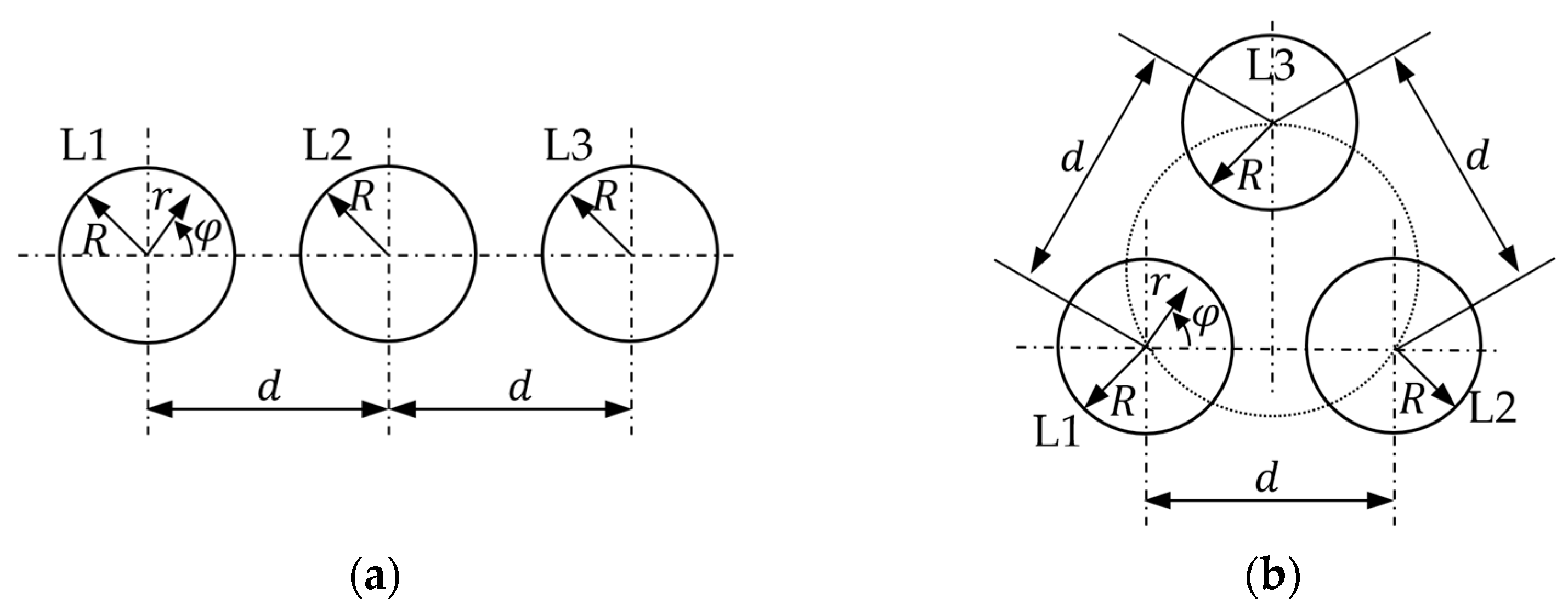
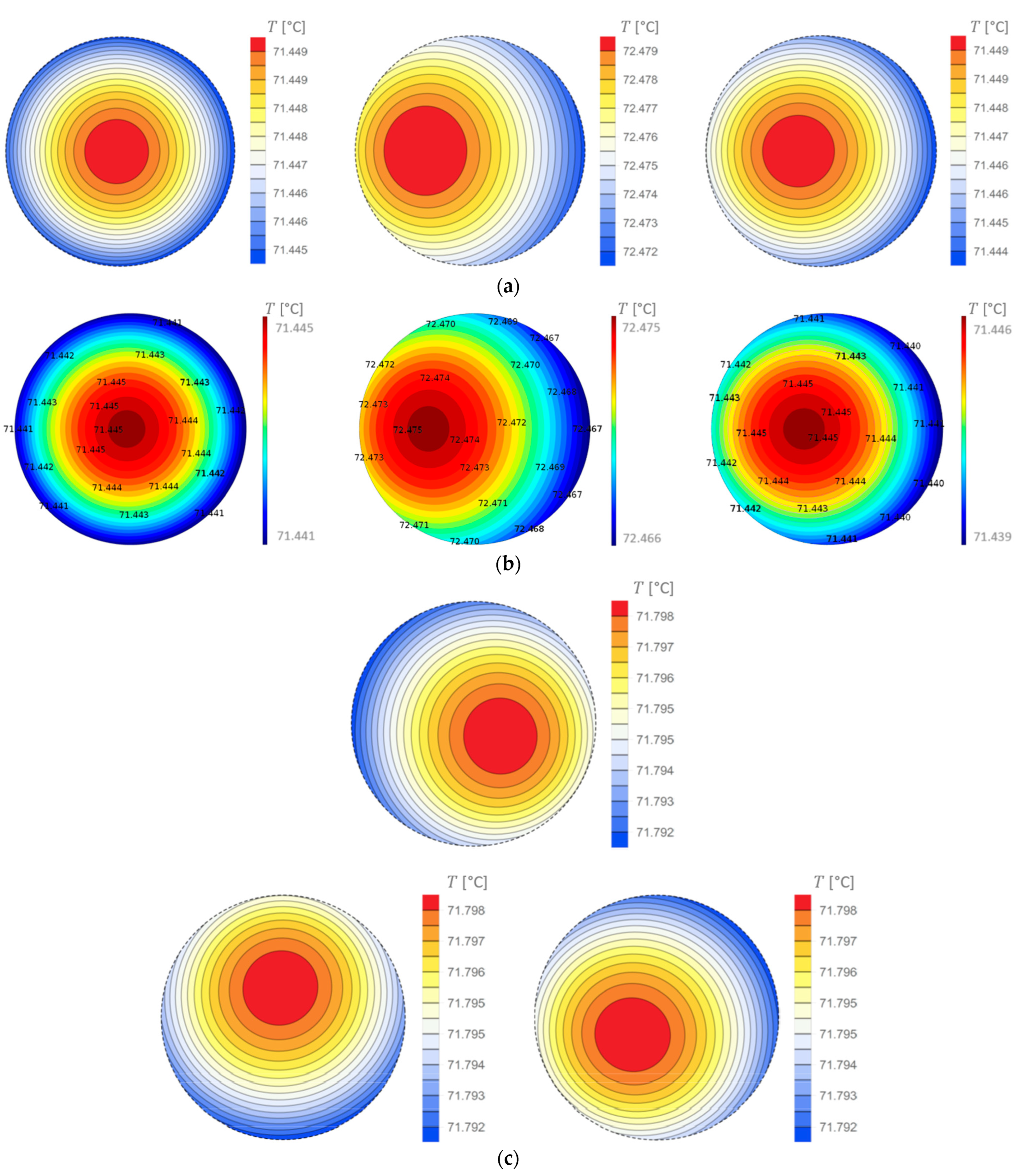
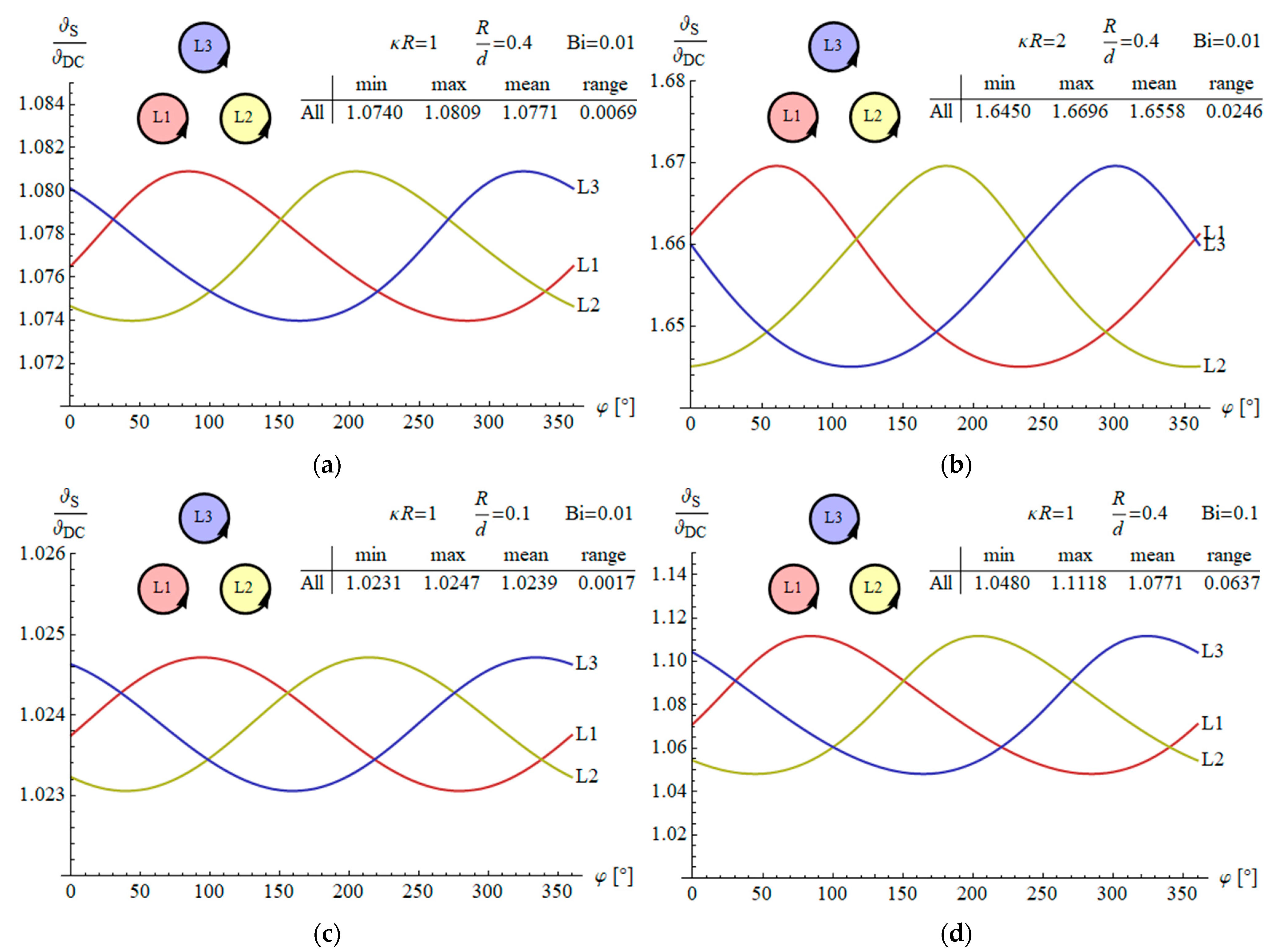
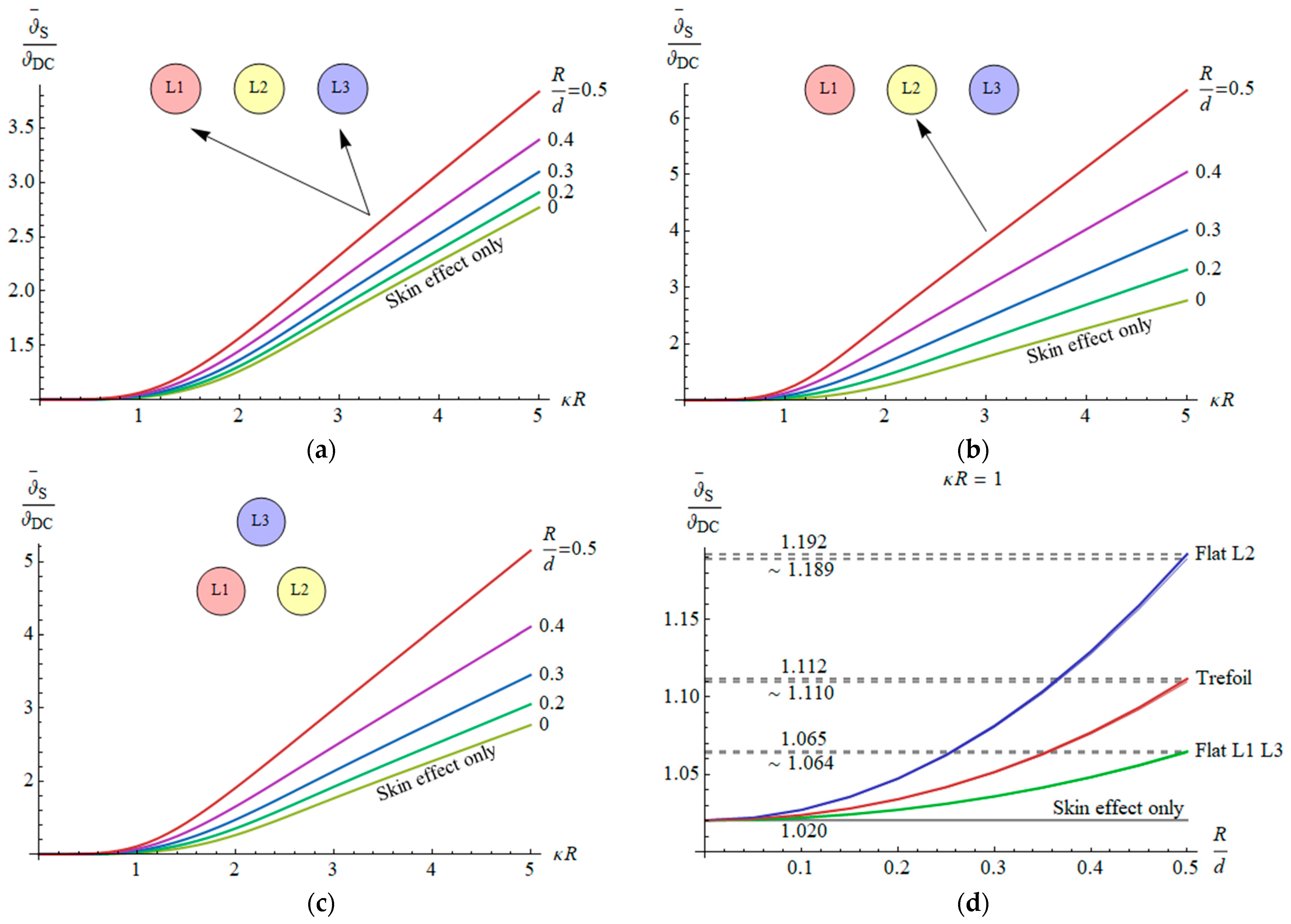
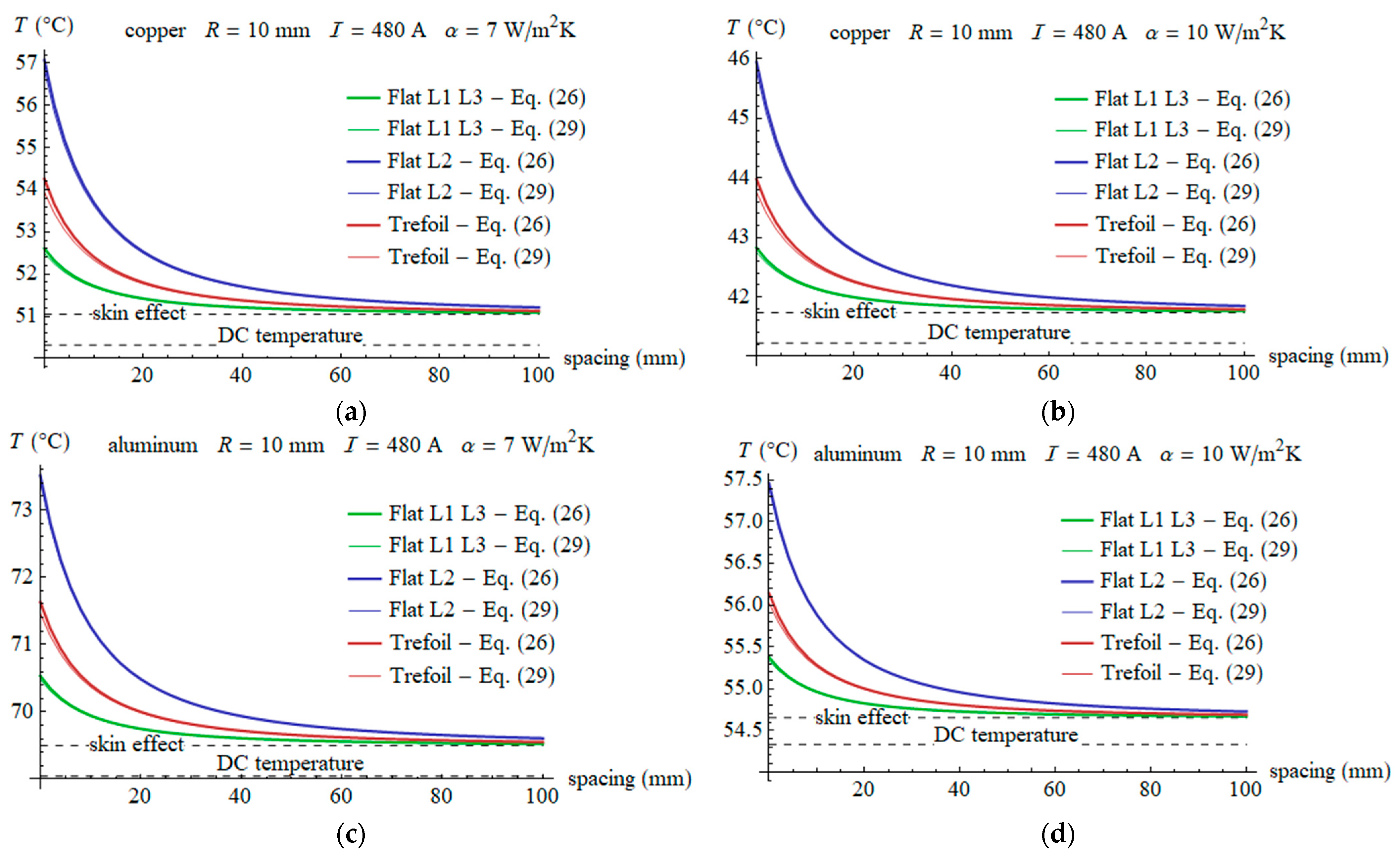
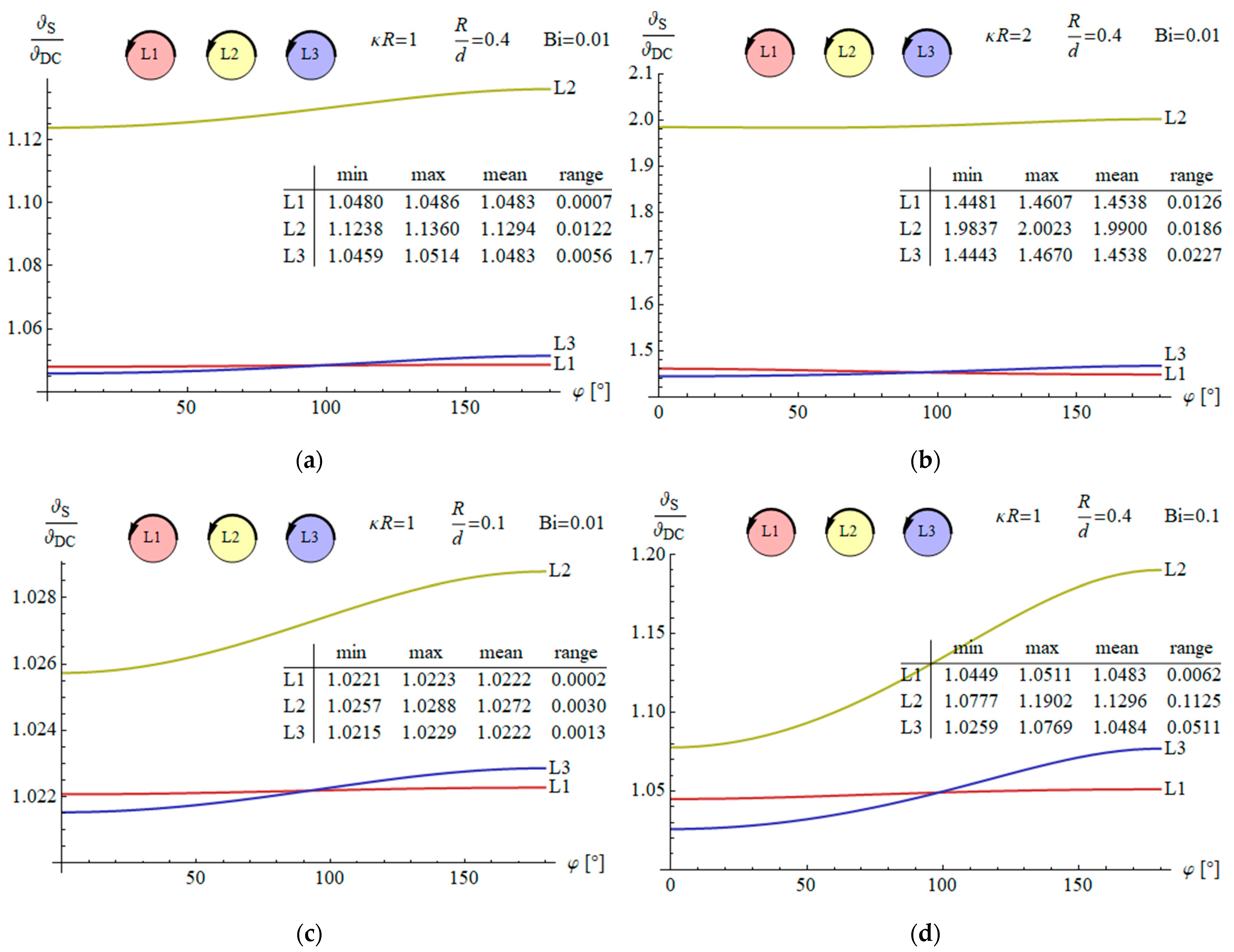
Section 3, the temperatures of individual conductors in flat and trefoil three-phase configurations are determined. Then, an analytical formula for mean surface temperature increase is obtained and the impact of various parameters is examined. An approximate formula of closed form is derived to assess the influence of the skin and proximity effects on the thermal field. Finally, numerical examples are presented to illustrate the considerations. Due to quite a large number of symbols occurring in the equations they were collected at the end of this manuscript.


