Article

Analysis of Hydrogen Combustion in a Spark Ignition Research Engine with a Barrier Discharge Igniter

1
Department of Engineering, University of Perugia, Via G. Duranti, 93, 06125 Perugia, Italy
2
Federal-Mogul Powertrain Italy, Via Della Scienza, 6/8, 41012 Carpi, Italy
*
Author to whom correspondence should be addressed.
Energies 2024, 17(7), 1739; https://doi.org/10.3390/en17071739
Submission received: 29 February 2024 / Revised: 27 March 2024 / Accepted: 2 April 2024 / Published: 4 April 2024
(This article belongs to the Section A5: Hydrogen Energy)

Abstract

:
Hydrogen fuel is gaining particular attention in internal combustion engines. In addition to zero-carbon emissions, major advantages relate to its combustion characteristics, which allow a significant increase in thermal efficiency under ultra-lean operation and with very low NOx levels. The ignition system is one of the main technology enablers, as it determines the capability to control ultra-lean operations, avoid backfire phenomena, and/or reduce the risks of abnormal combustions. The latter results from hydrogen’s low ignition energy and it is associated with factors like high-temperature residuals, hot spots, and irregular spark plug discharge. The ACIS gen 2-Barrier Discharge Igniter excels in accelerating the initial flame growth speed by the generation of non-equilibrium low-temperature plasma, a strong ignition promoter for the combined action of kinetic and thermal effects. Moreover, its volumetric discharge facilitates combustion initiation on a wide region, in contrast to the localized ignition of traditional spark systems. In this work we present for the first time, to the best of our knowledge, experimental results showing the performance of a hydrogen engine with a low-temperature plasma discharge. Tests were conducted on a single-cylinder research engine, achieving ultra-lean conditions with cycle-to-cycle variability results below 2.5%. The analysis indicates that the H2-BDI combined solution is capable of accelerating the evolution of the flame front compared to traditional spark plugs, leading to a significant reduction in the cycle-to-cycle variability. A meticulous adjustment of the BDI control parameters further enhances igniter performance and contributes to a deeper understanding of the innovative approach proposed in this study.

1. Introduction

In response to the imperative to reduce carbon emissions in the transportation sector and address air quality concerns, regulations related to pollutant emissions and greenhouse gases are driving the development of cleaner and more efficient internal combustion engines (ICEs) [1]. Advanced after-treatment systems, such as high-efficiency particulate filters (D/GPF), selective catalytic reducers (SCRs) with urea injection, and modern catalyst light-off strategies, are effectively minimizing pollutant emissions (NOx, CO, unburned hydrocarbons, and particulate matter) to nearly zero [2]. Traditional spark ignition (SI) engines face challenges in ensuring high performance together with low emissions [3]. In the context of modern spark ignition (SI) engines, the approach to reducing fuel consumption involves implementing high boost levels in conjunction with downsizing [4], along with the adoption of water injection [5], lean and/or exhaust gas recirculation (EGR) diluted mixtures [6]. It is crucial to explore contemporary combustion strategies like low-temperature combustions (LTCs) [7], increase the hybridization level of vehicles to meet the requirements of sustainable mobility [8], and promote the use of renewable and alternative fuels [9].
In this contest, hydrogen H2 is recognized as the energy vector guiding toward a fossil fuel-free future of mobility, since it stands out as the only fuel with the potential to eliminate carbon, carbon monoxide, and carbon dioxide emissions, allowing for high efficiencies under very lean combustion conditions [10]. The wide flammability limits and rapid flame propagation rate of hydrogen contribute to a stable combustion process, particularly for lean mixtures [11]. Hydrogen can be employed in an internal combustion engine in various modes, including dedicated fuel operation as well as in bi-fuel or dual-fuel configurations. Numerous studies have been conducted to promote the use of hydrogen fuel in internal combustion engines [12], whether as a sole fuel or by adding it to fossil fuels to enhance engine brake thermal efficiency and reduce exhaust emissions [13]. Due to the highly dilute mixtures and the elevated autoignition temperature, hydrogen engines can withstand higher compression ratios (up to 14.5:1) compared to gasoline engines [14]. This characteristic results in enhanced thermodynamic efficiency [15]. Consequently, the engine can operate with load quality regulation, eliminating the need for a throttle, and potentially achieving an engine efficiency of 52% [16]. As found by Shi et al. [17], the brake thermal efficiency witnessed an increase from around 10.0% to 16.7% under an excess air ratio of 1.3, when 6% of hydrogen was added to the gasoline of a retrofitted Wankel engine. Dimitriou et al. [18] demonstrated an enhancement in brake thermal efficiency, with the maximum improvement reaching approximately 3%, corresponding to an 80% addition of hydrogen energy. When pure hydrogen is utilized, HC and CO concentrations approach zero, with only minimal contributions from lubricating oil combustion [19]. Serin et al. [20] also showcased reductions in CO emissions through hydrogen additions, albeit accompanied by an increase in NOx emissions. In this context, water injection application is a promising and effective way to control NOx emissions and to reduce auto-ignition occurrences simultaneously in hydrogen engines [21]. Despite the mentioned benefits, the use of hydrogen in ICEs presents challenges, particularly in addressing abnormal combustion issues, both as an in-cylinder process or as a backfire in port fuel injection (PFI) engines [22]. The occurrence of such abnormal combustion in PFI engines hinders further advancements in engine performance. This is due to factors such as low ignition energy and high flame propagation velocity [23,24]. Abnormal combustion can also trigger engine knock, causing damage to cylinders and pistons [25,26]. Backfires in port fuel injection engines are typically caused by high residual exhaust gas temperature, hot spots, and abnormal ignitions, all of which heavily depend on the engine’s operating conditions [27,28]. To mitigate these challenges, preventing pre-ignition due to hot spots around the spark plug and reducing ghost spark phenomena related to standard ignition coils are crucial. As reported in [29], preventing pre-ignition can be achieved through the adoption of a cooled ignition system or unconventional ignition methods, like corona discharge, which not only prevents pre-ignition and anomalous combustions but also facilitates the ignition of highly diluted hydrogen-air mixtures [22]. Laser ignition represents another valuable technology enhancing advanced hydrogen spark ignition engines [30]. It is an electrode-less ignition and unlike traditional electrode-based ignition systems, laser ignition eliminates the risk of surface ignition, pre-ignition, and backfire, thereby significantly reducing these potential issues in hydrogen-fueled engines [31].
Recently, BDI systems have been introduced to generate a stronger ignition kernel with a larger ignition volume compared to traditional spark plugs, using controlled corona discharges. Such systems also overcome the limited operating conditions of streamer-type corona igniters, while maintaining the advantages related to the generation of low-temperature plasma and volumetric ignition. By generating ionization waves through the corona effect, BDI stands out in enhancing the initial flame growth speed. This is achieved through the creation of non-equilibrium low-temperature plasma, acting as a potent ignition promoter by combining kinetic and thermal effects [32,33]. Additionally, the BDI volumetric discharge allows for combustion initiation across a broad region, contrasting with the localized ignition typical of traditional spark systems [34]. Results from the same research group demonstrated the capability of BDI to extend the lean stable limit if compared to traditional spark ignition when operating with fuels like gasoline E5 and ethanol E85 [35]. Moreover, the lack of a prominent ground electrode in the BDI system serves to minimize heat losses and eliminates hot points susceptible to pre-ignition. Additionally, the power electrode remains indirectly exposed to the effects of excited species generated during the discharge [36]. Using a single cylinder research engine operating at 1000 rpm and in low-load conditions (IMEP = 4.5 bar at λ = 1.0 when operating with spark-E5 [37]), a first experimental campaign was conducted.

Present Contribution

Within this context, the present work presents, for the first time to the best of our knowledge, experimental results showing the performance of a hydrogen engine with a low-temperature plasma (LTP) discharge, namely Advanced Corona Ignition System second-generation Barrier Discharge Igniter (ACIS gen2-BDI) [38,39]. A comparison between the performance of ACIS gen 2-BDI and a conventional spark plug was conducted in H2 to assess the differences in terms of control, combustion behavior, and the ability to extend the lean stable limit of the engine. Lambda sweeps are also discussed.

2. Materials and Methods
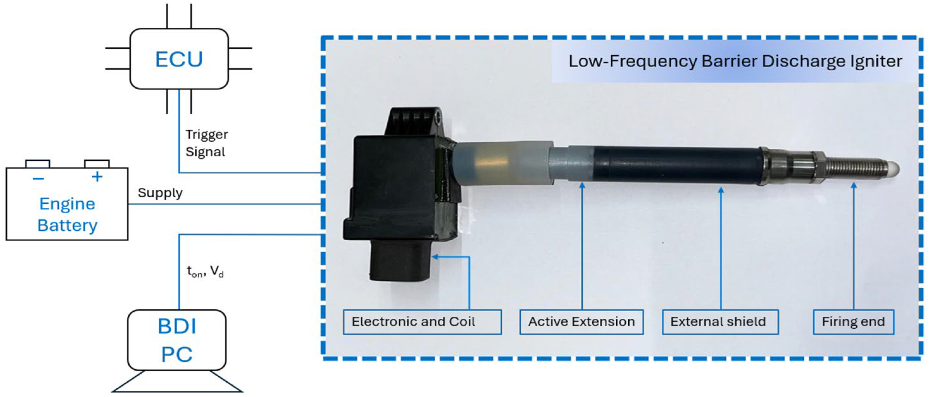
2.1. Igniter

An ACIS gen2-BDI prototype was selected as the igniter, supplied by Federal-Mogul Powertrain Italy, a Tenneco Group Company, which is capable of generating a robust electric field within the combustion chamber at a frequency of approximately 100 kHz. This device is referred to as ACIS gen2-BDI to distinguish it from a previously studied prototype by the same research group, which operates at an input frequency of around 1.04 MHz [35,37]. The streamers produced by ACIS gen2-BDI start from the annular grounded electrode, located along the base circumference of the igniter, and propagate on the surface of the dielectric material that covers the counter-electrode. The corona igniter, as depicted in Figure 1, can directly receive power from the engine battery and trigger signals from the engine control unit. To enhance control over the voltage supplied to ACIS gen2-BDI during tests, an external power supply was utilized. An in-house software facilitates the adjustment of control parameters for device ignition, including the driving voltage (Vd) and activation time (ton). These parameters are respectively associated with the peak electrode voltage reached at the igniter’s firing end and the discharge duration of the device [38,39]. From here on, ACIS gen2-BDI will be referred to as BDI for the sake of simplicity.

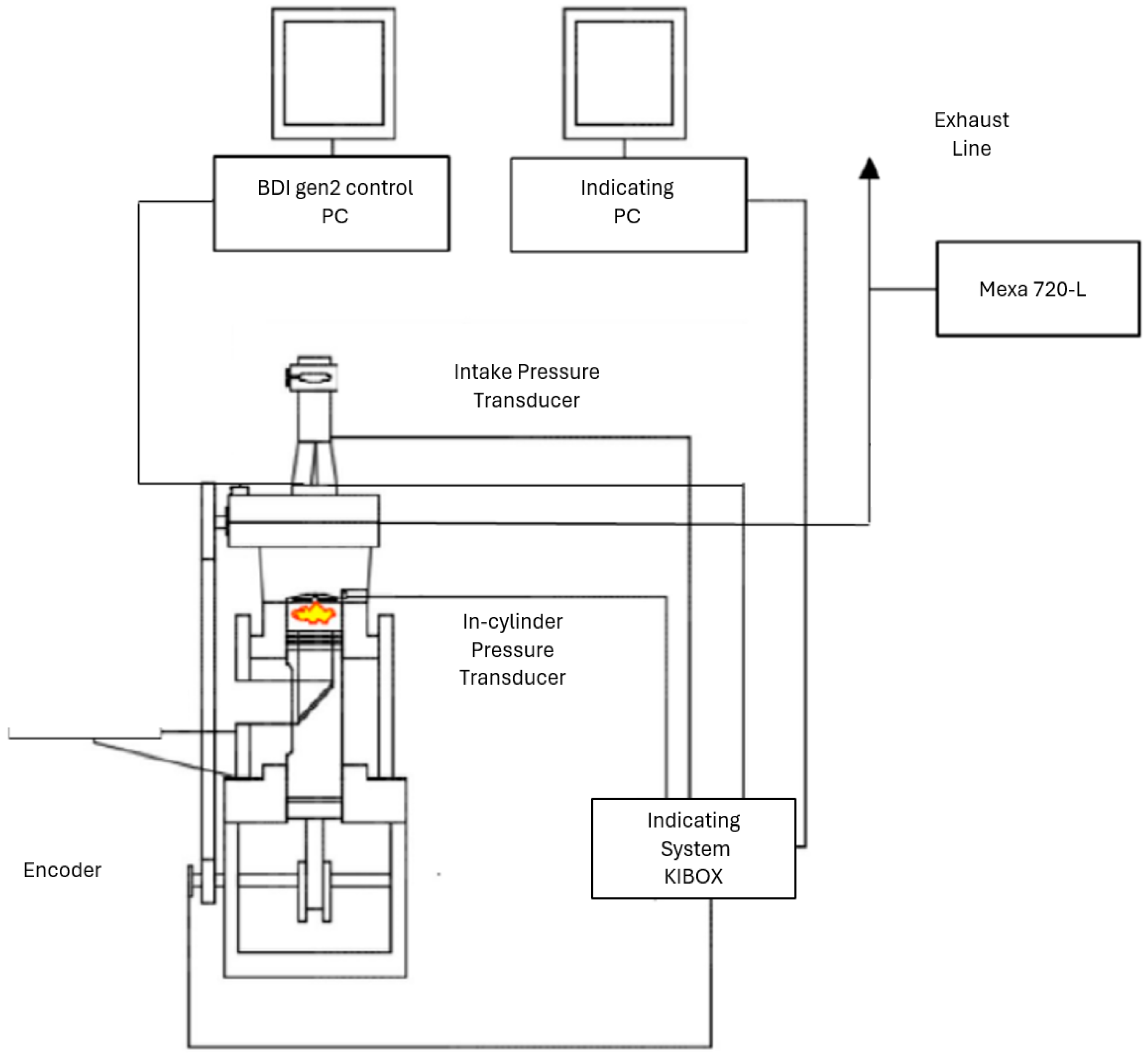
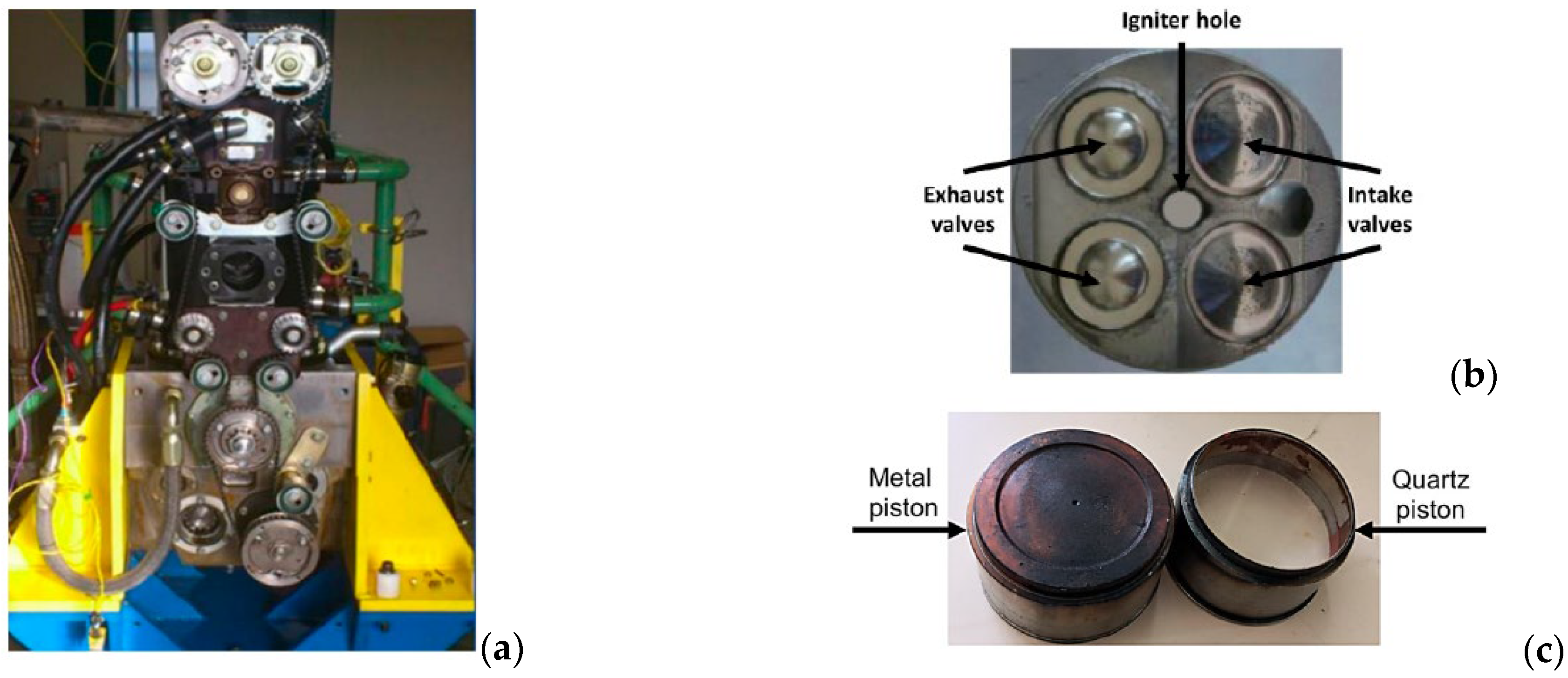
2.2. Single Cylinder Research Engine

Measurements were performed on a 500-cc single-cylinder research engine (Figure 2 and in Table 1). The engine is configured to allow optical access, however, for the present investigations the quartz piston crown was replaced by a metal one. The optical configuration requires dry contact between cylinder liner and piston rings, so these are made using a blend of Teflon and graphite [37,40].
In the present study, the engine operated at 1000 rpm in PFI mode, and in throttled condition, by setting the throttle valve at a fixed angle position. The relative air–fuel ratio λ was controlled by adjusting the hydrogen fuel injected quantity, which was injected at a fixed pressure of 4 bar absolute. IMEP, depending on the condition, ranged approximately from 3 to 4 bar. A research ECU (Athena GET HPUH4) controlled the energizing time of the injector and the ignition timing (IT) by sending a trigger signal to the igniter control unit.
A Kistler Kibox combustion analysis system (Figure 3), with an angular resolution of 0.1 CAD, acquired the following data:
  • The intake port pressure signals from a Kistler 4075A5 piezoresistive transducer;
  • The in-cylinder pressure signals from a Kistler 6061B piezoelectric transducer;
  • The absolute crank angle position from an AVL 365C optical encoder;
  • The O2% from a Horiba Mexa 720 fast probe (accuracy +/−2.5%);
  • The ignition signal from the engine control unit.
For each test point, 103 consecutive cycles were recorded. Through the indicating analysis, from the raw in-cylinder pressure signals, all common combustion metrics were determined.
During engine operation, the λ value detected by the fast probe was adjusted in real-time towards the desired value based on the O2% concentration, using the formula proposed by Azeem et al. [41] (Equation (1)):
λ = 1 + X O 2 1 X O 2 Y O 2
where X O 2 and Y O 2 are the wet concentrations of oxygen in the exhaust gas and intake air, respectively.

2.3. Test Campaign

The experimental campaign was based on the examination of the BDI’s performance at lean conditions on a conventional PFI engine using hydrogen H2 at low speed (1000 rpm) and low load.
The primary stage consisted of the investigation carried out on the BDI’s control parameters at λ = 1.6. By setting the activation time to ton = 2 ms, we first optimized the combination with Vd = 11 V in terms of ignition timing to determine the MBT. Following that, we carried out the same optimization process, this time considering Vd = 12.5 V.
Subsequently, the aim was to conduct a comparative analysis, under the same operating conditions (λ = 1.6), evaluating the performance achieved with the ignition of both gasoline E5 and hydrogen H2 using the BDI system. This assessment encompassed a comprehensive examination of various parameters, including indicating data (AI05, AI50, AI90, IMEP, and CoVIMEP), in-cylinder pressure, and IHRR (integral heat release rate), considering the ignition timing optimized for each scenario.
Furthermore, a comparison between the traditional spark igniter and the BDI was made to discern the propensity for backfiring induced by the utilization of the traditional ignition system in conjunction with hydrogen as the fuel source.
In the conclusive step of this investigation, under the optimized operating conditions of the BDI system, the air–hydrogen mixture was progressively leaned out, from λ = 1.6 to λ = 2.3. To achieve a more optimal and stable combustion process, considering the indicating data, in-cylinder pressure, and IHRR, by centering half of the combustion within the MBT area, the IT has to be advanced moving towards leaner conditions because of the combustion duration increment.

3. Results and Discussions

First, several tests are presented at λ = 1.6, starting with the optimization of the BDI system performance by adapting its control parameters to hydrogen (Section 3.1). Next, two comparisons are presented, one between hydrogen and gasoline with BDI igniters (Section 3.2), and one between BDI and traditional spark with hydrogen fuel (Section 3.3).
Then, tests with the BDI system from λ = 1.6 up to λ = 2.3 are presented, showing engine performance obtained under leaner conditions (Section 3.4).

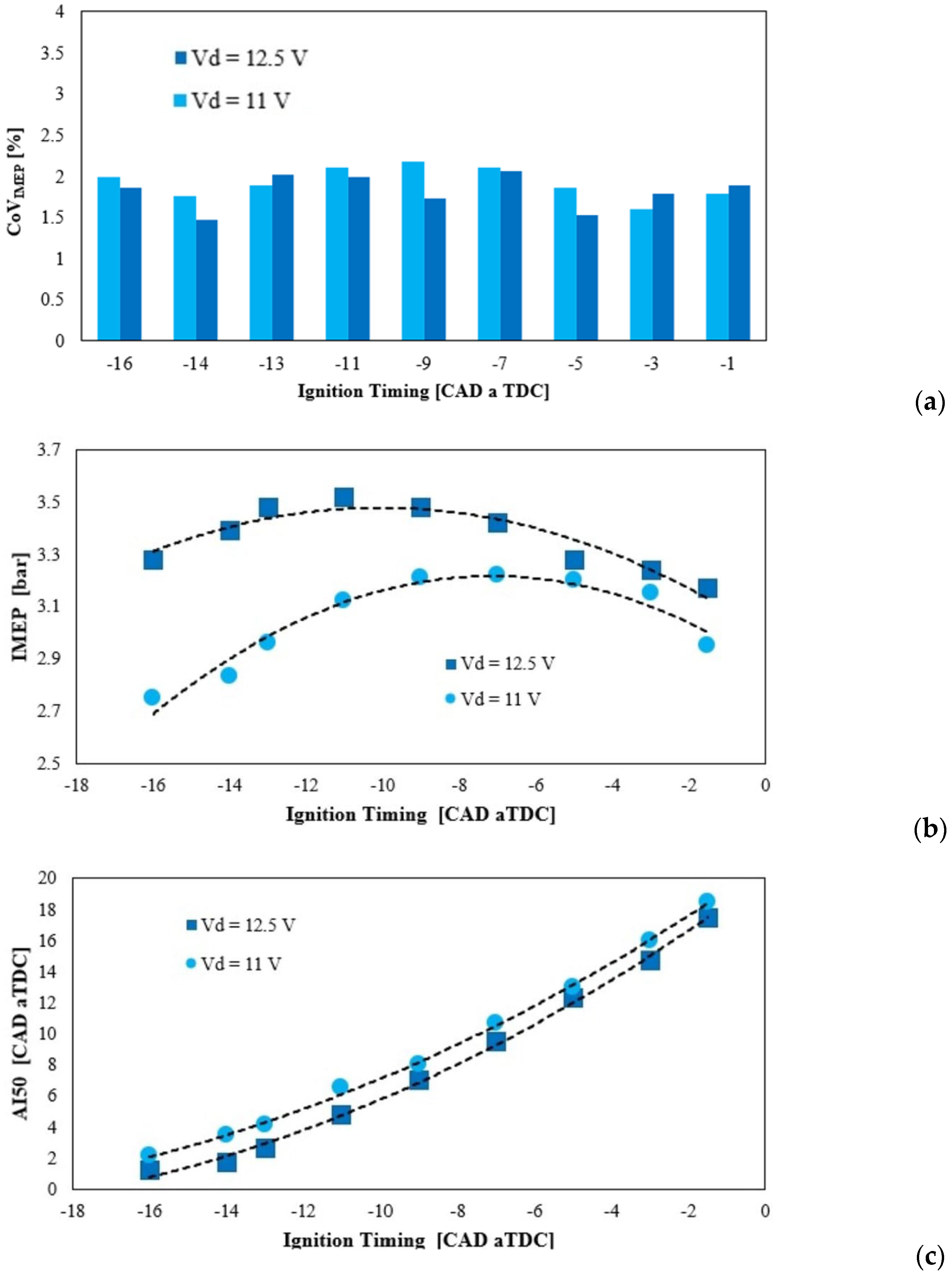
3.1. Optimization of the BDI Performance at λ = 1.6

Figure 4 shows the results of the investigation carried out on the BDI’s control parameters at λ = 1.6. By fixing the activation time to ton = 2 ms, first, the combination presenting Vd = 11 V was optimized in terms of ignition timing to determine the MBT. After that, the same optimization process was also realized by considering Vd = 12.5 V, which is considered the maximum level generally attainable with a standard battery.
Combustion stability (Figure 4a) was evaluated using the coefficient of variance of the indicated mean effective pressure (CoVIMEP), namely, the ratio between the IMEP standard deviation and IMEP mean value. Figure 4a depicts the CoVIMEP values found for each ignition timing tested. Engine operating points can be considered as fully stable if the CoVIMEP is lower than about 3–4%. Every tested condition has demonstrated full stability by consistently exhibiting a CoVIMEP lower than 2.5%. Both configurations (i.e., Vd = 11 V, ton = 2 ms and Vd = 12.5 V, ton = 2 ms) exhibit a similar IMEP trend in response to changes in ignition timing (Figure 4b). Specifically, the configuration with 12.5 V demonstrates a higher IMEP value compared to the 11 V case, attributed to the effects on the combustion process associated with the greater ignition energy released into the medium [39]. For instance, when considering the MBT timing, i.e., −7 CAD aTDC for 11 V and −11 CAD aTDC for 12.5 V, the latter is capable of increasing power output by approximately 9%. Since fueling is fixed for all these points, this translates into an equivalent efficiency gain. Simultaneously, a comparison between the 12.5 V MBT point and the 11 V point at the same ignition timing indicates a gain in delivered IMEP of about 12% for the high voltage case. On retarded spark timings, i.e., if considering the interval between −1 and −7 CAD aTDC, the two voltage settings perform about the same in terms of delivered work. However, as the ignition timing advances, the 12.5 V configuration has the ability to enhance the IMEP significantly compared to the 11 V configuration, as displayed in Figure 4b.
The results also show that the increased ignition energy released by the 12.5 V configuration enables the acceleration of the initial flame front propagation, as depicted in Figure 4c, where AI50 is displayed against IT. AI50 is defined as the crank angle degree after the top dead center (TDC) at which 50% of the fuel mass is burned. The 12.5 V supply consistently advances the AI50 values, which means that the early stage of the combustion development is shortened.
Overall, the 12.5 V configuration allows an increase in the work done, as displayed in terms of IMEP in Figure 4b. Furthermore, it is worth recalling that each operating point tested in this λ condition shows a CoVIMEP lower than 2.5% for both configurations, as seen in Figure 4a, thus ensuring stable combustion. Based on these results, the subsequent analyses will refer to the 12.5 V configuration.

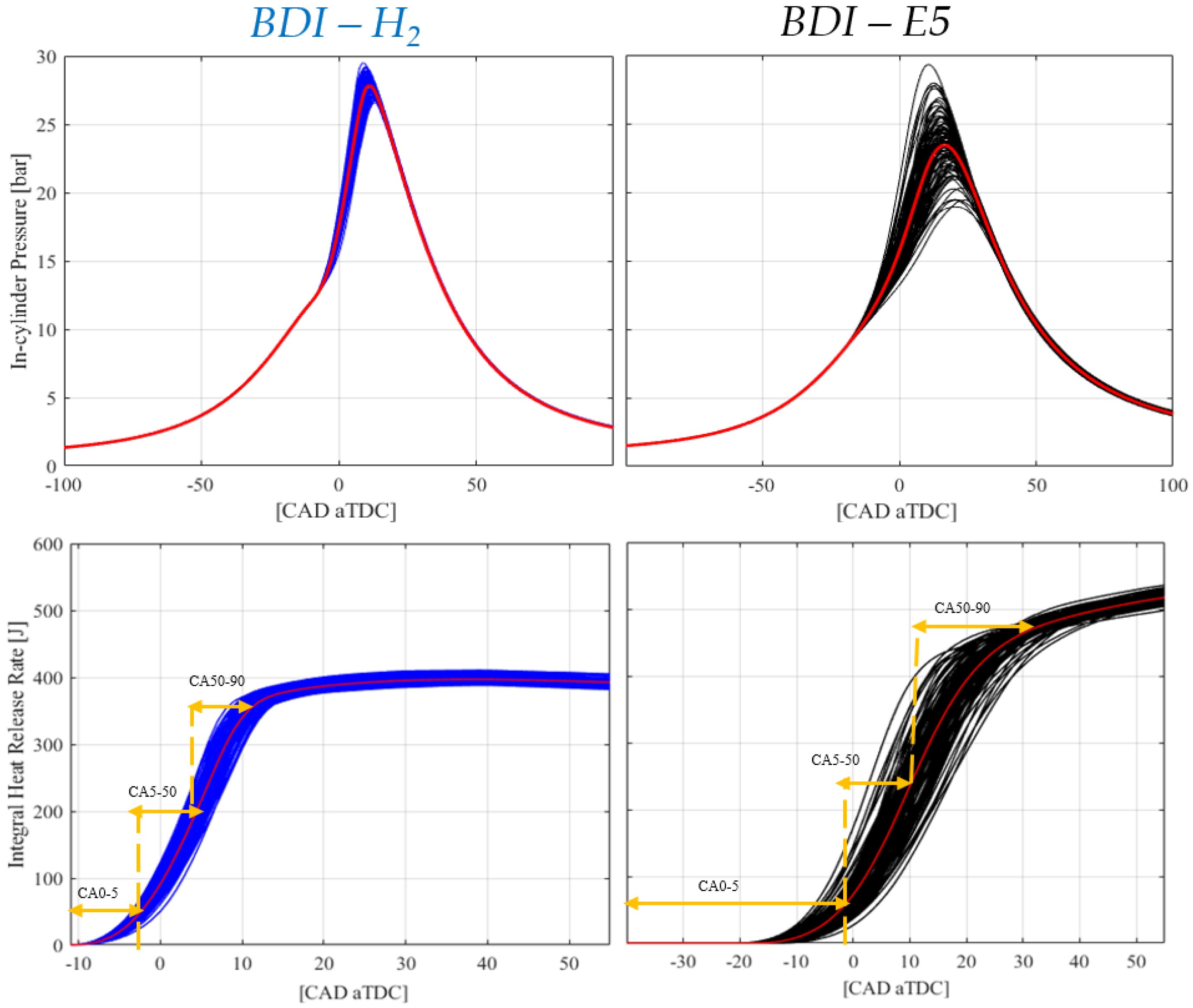
3.2. Analysis of the BDI Performance at λ = 1.6 in H2 and Conventional Gasoline E5

Figure 5 shows the comparison between the performances obtained by using gasoline E5 and hydrogen H2 both ignited by BDI. Both configurations use IT for MBT, at λ = 1.6. In-cylinder pressure traces of H2 are shown with blue curves alongside those of E5, reported in black. As can be observed, the H2 operating point with IT = –11 CAD aTDC can deliver approximately 3.56 bar of IMEP (Table 2). Such a value corresponds to approximately 400 J/cycle, as indicated by the integral of the apparent heat release rate in Figure 5 (blue curves). When compared to the E5 application at the same λ value, this value is about 0.97 bar lower than the one achieved through gasoline fuel, which was found to be equal to 4.49 bar. Such a value corresponds to approximately 530 J/cycle, as indicated by the integral of the apparent heat release rate in Figure 5 (black curves). Since fueling is clearly different in this case, the indicated efficiency can be considered to better compare the performance. The hydrogen indicated efficiency is 29.7% and the gasoline indicated efficiency is 28.8% (Table 2). The benefit obtained with hydrogen can be attributed to the much faster combustion development, as demonstrated in Table 2, with for example CA 5–90 = 15.0 CAD with hydrogen compared to CA 5–90 = 34.2 CAD with gasoline. The slopes of the integrated heat release rate curves in Figure 5 also show such differences.
In comparison to H2, E5 displays pressure curves marked by a higher CoVIMEP (2.8%), suggesting a tendency towards unstable operating conditions. Given the optimized IT for both scenarios, it is important to note that hydrogen demands much smaller IT values (–11 CAD aTDC) compared to gasoline (−38 CAD aTDC). The need for reduced ignition timing with H2 compared to E5 is related to the combustion characteristics and properties of the respective fuels [42]. For example, the elevated flame speed of hydrogen results in quicker ignition and flame spread [22]. Additionally, the broader flammability range, combined with low ignition energy, facilitates the easy ignition of H2 across a wide spectrum of air–fuel ratios [22].
These factors collectively emphasize the high flame speed of hydrogen. The lower IMEP value obtained with H2 is related to the lower energy content per unit volume compared to gasoline, because of the reduced volumetric efficiency of the H2-PFI operation mode. Despite its higher energy content per unit mass, the lower density of hydrogen, when injected in the intake port, results in a reduced total energy (cf. integral of heat release rate), impacting the overall power output [43]. Despite this, the indicated fuel efficiency is higher with hydrogen, as discussed above. Table 2 summarizes the main features of the operating points compared.

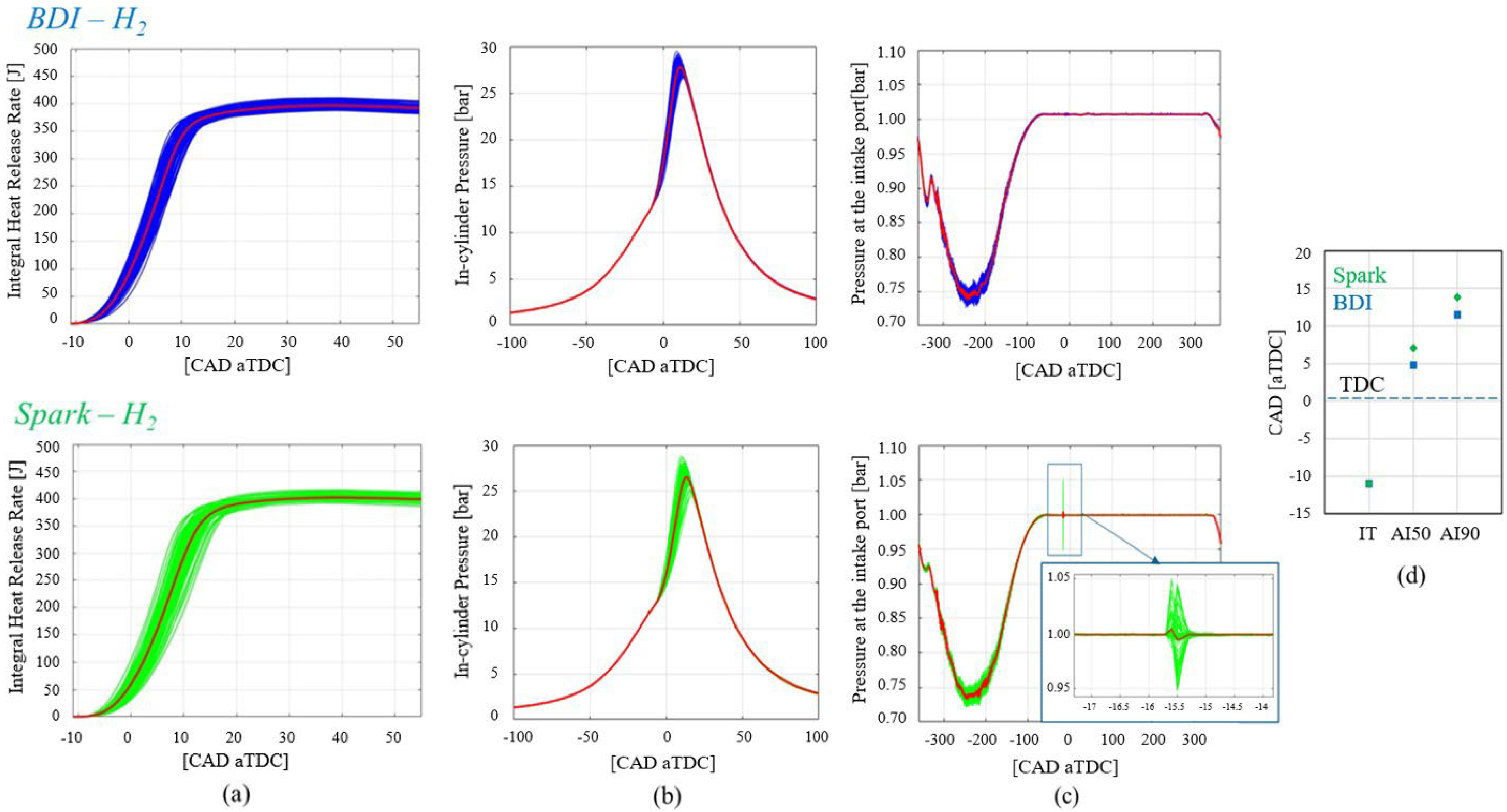
3.3. Comparison between Traditional Spark and BDI at the Same IT in H2

At the same λ = 1.6, Figure 6 reports the in-cylinder and intake port pressure traces recorded with H2 when ignited by traditional spark (green curves) and BDI (blue curves). The same IT was utilized for both igniters with BDI presenting the optimized configuration of Vd = 12.5 V and ton = 2 ms. By using the same input conditions, i.e., the same IT (equal to –11 CAD aTDC), BDI advances the combustion process by about 3 CAD (Figure 6a,b,d) thanks to the low-temperature plasma and volumetric discharge effect, as expected [37]. The acceleration of the flame front plays a crucial role in extending the lean stable limit of the engine [34]. Under these operating conditions, BDI demonstrates its potential application for higher λ values, aiming to extend the lean stable limit compared to conventional spark ignition. Furthermore, the low engine speed and load conditions, as those set in the tests, together with the lean air–fuel ratio, and the short duration of the tests, prevent the attainment of high temperatures. Consequently, backfires remain few and may go undetected by the cylinder pressure sensor. However, the intake pressure can exhibit spikes detected by the sensor when the conventional spark ignition system is used; a pattern never observed in the case of BDI. In Figure 6c the phenomenon of backfire attributable to traditional spark plug utilization is underscored. It is acknowledged that to properly explain this phenomena further investigations will be needed, including new dedicated tests and also detailed 3D simulations. At the present time such a behavior could be attributed to the enhanced combustion efficiency with BDI combined with reduced cyclic variability, which reduces the presence of unburned H2 that might re-enter the intake during valve overlap and aspiration phase. The conditions where no backfire event occurred may therefore be linked to the different igniter characteristics.
Considering the results obtained so far, additional operating points with the conventional spark were not explored further. Instead, optimization efforts were directed towards the BDI system, focusing on exploring and optimizing ignition timings at two other distinct λ values, specifically λ = 2.0 and λ = 2.3 (Section 3.4).

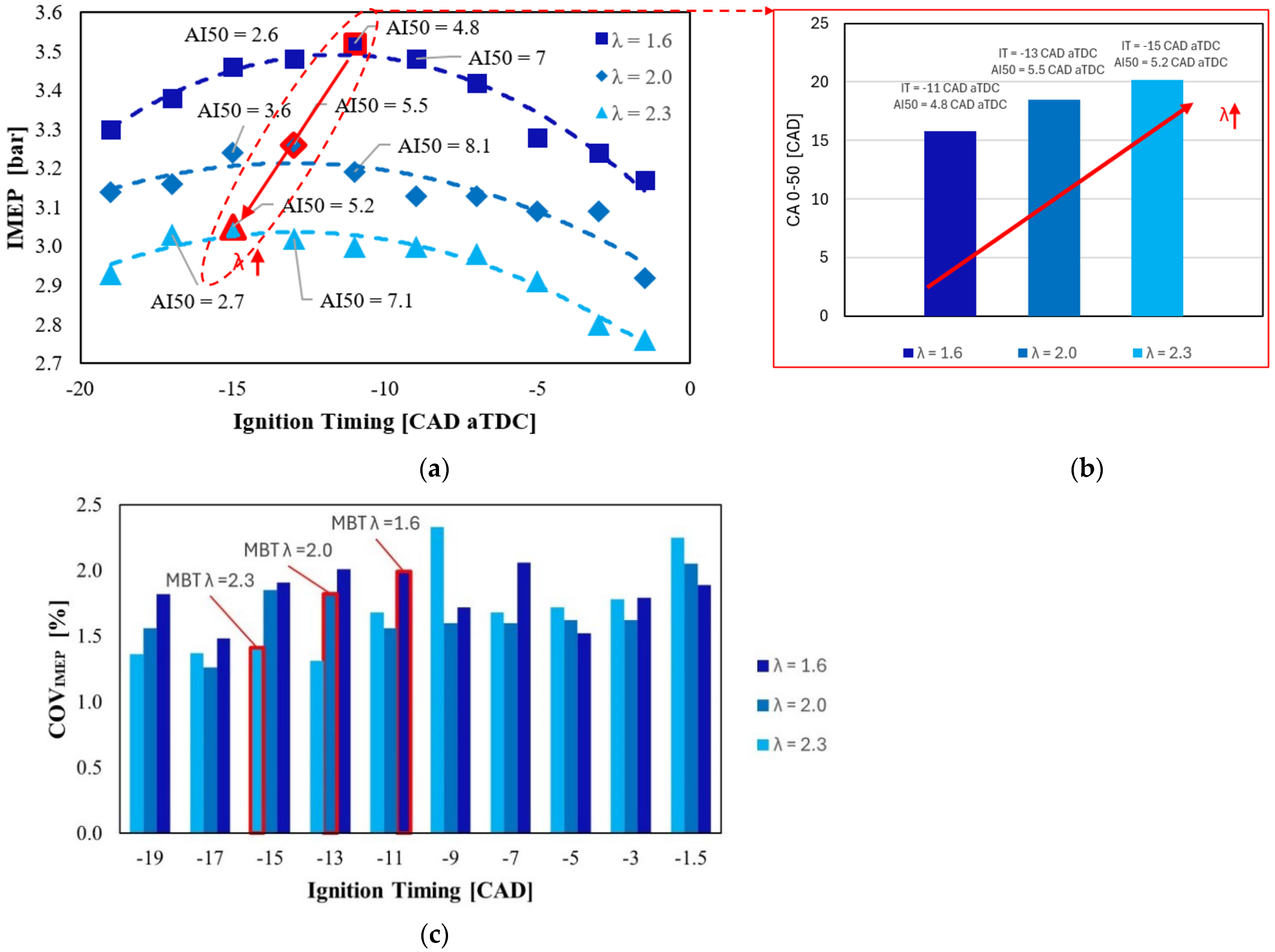
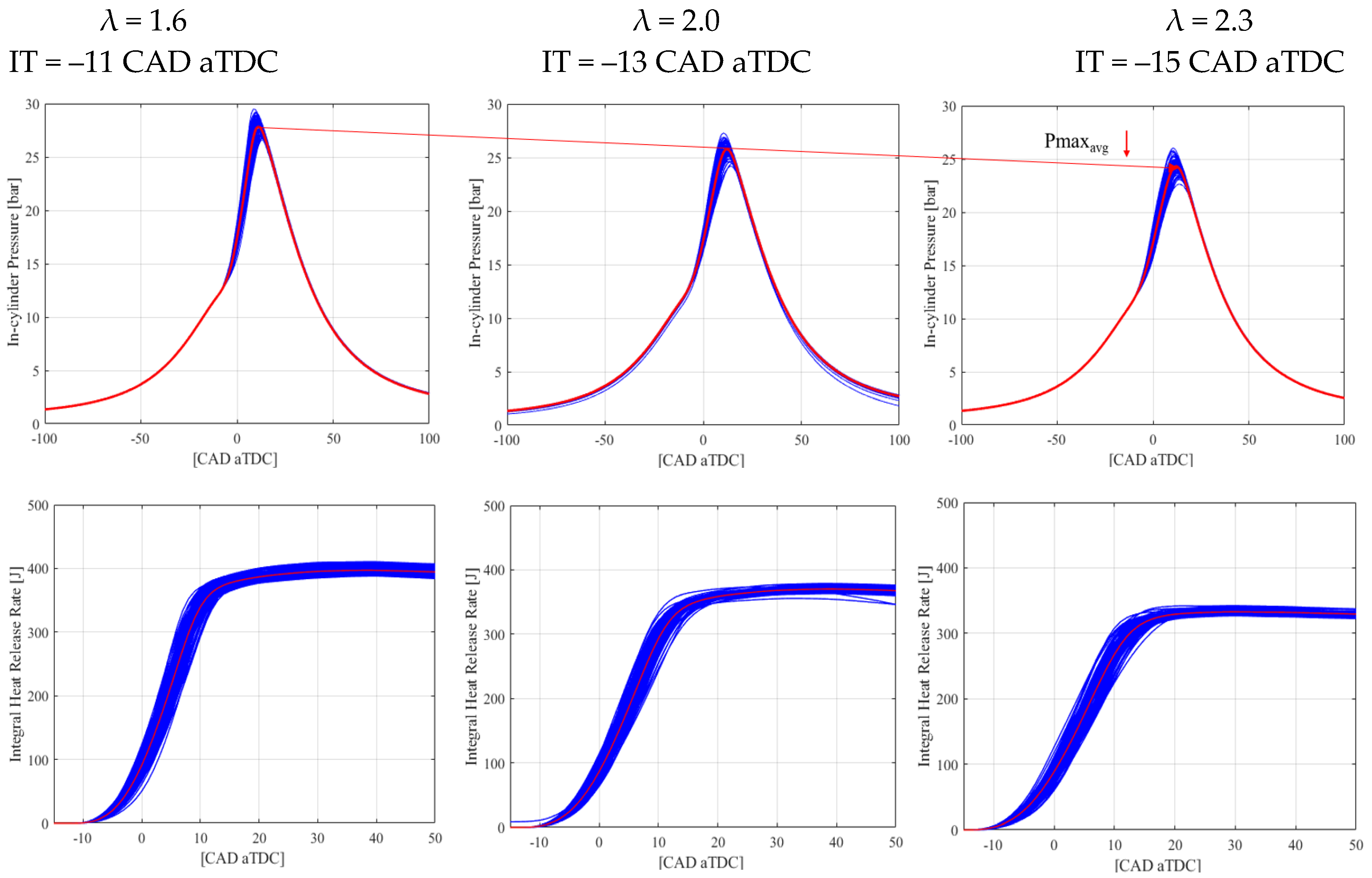
3.4. Tests up to λ = 2.3 with H2 and BDI

Figure 7 illustrates the optimization of performance through IT adjustment at the three distinct λ values examined in this study. To ensure optimal performance, IT must be advanced by moving towards leaner conditions because of the combustion duration increase (Figure 7a) [35]. The maximum in-cylinder pressure (Figure 8) and IMEP tend to decrease as the mixture is leaned, attributed to the diminished amount of fuel injected into the chamber [35]. For each λ tested, the MBT was obtained with the AI50 around 4–7 CAD aTDC (values reported in Figure 7a,b), as previously shown in Figure 4. Furthermore, unlike other fuels previously tested on the same engine [35,37], the rise in CoVIMEP (Figure 7c) is not as pronounced when leaning the mixture. This phenomenon is likely attributed to the broader flammability and stability range of hydrogen across a wider lambda range [11]. For the sake of completeness, Figure 8 displays the in-cylinder pressure traces at each λ analyzed and the corresponding integral of heat release rate (IHRR).

3.5. Discussion

Through careful fine-tuning of the ACIS gen 2-BDI control parameters, the performance of the igniter is improved and adjusted for hydrogen combustion. The results show the ACIS gen 2-BDI system’s capacity to accelerate the flame front propagation. Hydrogen displays lower IMEP if compared to a gasoline E5 application but superior combustion stability with reduced cycle-to-cycle variability. Hydrogen’s lower ignition timing requirement stems from its combustion traits, including higher flame speed and wider flammability range. When compared to traditional spark ignition, the ACIS gen 2-BDI system allows accelerating combustion by reducing the CA 0–50, without causing risks of backfire events. The more robust combustion initiation obtained with BDI results also in a notable decrease in the observed cycle-to-cycle variability.

4. Conclusions

This investigation focused on the optimization of ACIS gen2-BDI system performance, focusing on hydrogen fuel. This study examined control parameters, combustion stability, and in-cylinder pressure traces to assess the system effectiveness. Various levels of mixture leanness were also tested. The main findings of the work can be summarized in the following points:
  • At λ = 1.6, the BDI system demonstrated consistent stability across various ignition timings and driving voltages. The configuration with a higher driving voltage (12.5 V) exhibited enhanced performance in terms of higher IMEP for any ignition timing, indicating the potential for increased power output.
  • Comparing hydrogen and gasoline E5 at λ = 1.6, hydrogen-PFI showed a lower IMEP but better combustion stability with a lower CoVIMEP. The shorter ignition timing requirement for hydrogen was attributed to its combustion characteristics, including higher flame speed and broader flammability range.
  • Additionally, comparing the BDI and traditional spark ignition systems at the same ignition timing for hydrogen, the BDI system demonstrated the ability to shorten the first stage of the combustion process, shown by the reduction in the CA 0–50, compared to the traditional spark.
  • Under the same conditions, a reduced risk of backfire events with the BDI system was observed. This might be attributed to lower residual energy stored in the coil and to enhanced combustion efficiency.
  • Investigations were also extended to leaner conditions (λ = 2.0 and λ = 2.3), emphasizing the need for advanced ignition timing to optimize combustion timing and therefore power output. Despite a decrease in maximum in-cylinder pressure and IMEP as the mixture leaned, the BDI system exhibited very good stability with hydrogen.
In summary, the BDI system demonstrated promising capabilities in enhancing combustion characteristics and stability under lean operations, also with hydrogen fuel.

Author Contributions

Conceptualization, F.R. and M.B.; methodology, F.R., M.A. and S.P.; software, F.R. and M.A.; validation, S.P. and M.B.; formal analysis, J.Z. and S.P.; investigation, F.R., M.A. and S.P.; data curation, F.R., M.A. and S.P.; writing—original draft preparation, F.R.; writing—review and editing, F.R., J.Z. and M.B.; visualization, F.R. and M.A.; supervision, C.N.G. and M.B.; project administration, C.N.G. and M.B.; funding acquisition, M.B. All authors have read and agreed to the published version of the manuscript.

Funding

This research was partially funded by Ministero dell’Istruzione, dell’Università e della Ricerca (MIUR), Italy, through the PRIN 2020 funding source, project H2ICE, grant number 2020R92Y3Z, and by the University of Perugia grant “Fondo Ricerca di Ateneo, edizione 2021”. The igniters used for this research were provided by Federal Mogul Powertrain Italy, a Tenneco Group Company.

Data Availability Statement

Dataset available on request from the authors.

Conflicts of Interest

Author Stefano Papi was employed by the company Federal Mogul Powertrain Italy. The remaining authors declare that the research was conducted in the absence of any commercial or financial relationships that could be construed as a potential conflict of interest. The authors declare that this study received in-kind funding from Federal Mogul Powertrain Italy, providing the devices used for the research. The funder was not involved in the study design, collection, analysis, interpretation of data, the writing of this article, or the decision to submit it for publication.

Nomenclature

aBDCAfter bottom dead center
ACISAdvanced corona ignition system
AI05Crank angle degree after the top dead center (TDC) at which 5% of the mass is burned
AI50Crank angle degree after the top dead center (TDC) at which 50% of the mass is burned
AI90Crank angle degree after the top dead center (TDC) at which 90% of the mass is burned
aTDCAfter top dead center
BDIBarrier discharge igniter
CA 0–5Crank angle degree from IT to AI05
CA 0–50Crank angle degree from IT to AI50
CA 5–50Crank angle degree from AI05 to AI50
CA 5–90Crank angle degree from AI05 to AI90
CA 50–90Crank angle degree from AI50 to AI90
CADCrank angle degree
COCarbon monoxide
CoVIMEPCoefficient of variance of IMEP
DIDirect injection
D/GPFHigh-efficiency particulate filters
E5Gasoline (regular European gasoline, containing 5% ethanol)
E85Ethanol (blend with 85% ethanol, rest gasoline)
ECUEngine control unit
EGRExhaust gas recirculation
H2Hydrogen
HCHydrocarbons
ICEInternal combustion engine
IHRRIntegral heat release rate
IMEPIndicated mean effective pressure
ITIgnition timing
λRelative air–fuel ratio
LTCLow-temperature combustion
LTPLow-temperature plasma
MBTMaximum brake torque
NOxNitrogen oxides
O2Oxygen
PFIPort fuel injection
SCRSelective catalytic reducers
SISpark ignition
tonActivation time
VdDriving voltage

References

  1. Suresh, D.; Porpatham, E. Influence of high compression ratio and hydrogen addition on the performance and emissions of a lean burn spark ignition engine fueled by ethanol-gasoline. Int. J. Hydrogen Energy 2023, 48, 14433–14448. [Google Scholar] [CrossRef]
  2. Reitz, R.D.; Ogawa, H.; Payri, R.; Fansler, T.; Kokjohn, S.; Moriyoshi, Y.; Agarwal, A.; Arcoumanis, D.; Assanis, D.; Bae, C.; et al. IJER editorial: The future of the internal combustion engine. Int. J. Engine Res. 2020, 21, 3–10. [Google Scholar] [CrossRef]
  3. Duan, X.; Xu, L.; Xu, L.; Jiang, P.; Gan, T.; Liu, H.; Ye, S.; Sun, Z. Performance analysis and comparison of the spark ignition engine fuelled with industrial by-product hydrogen and gasoline. J. Clean. Prod. 2023, 424, 138899. [Google Scholar] [CrossRef]
  4. Dernotte, J.; Najt, P.M.; Durrett, R.P. Downsized-Boosted Gasoline Engine with Exhaust Compound and Dilute Advanced Combustion. SAE Int. J. Adv. Curr. Pract. Mobil. 2020, 2, 2665–2680. [Google Scholar] [CrossRef]
  5. Zembi, J.; Battistoni, M.; Mariani, F.; Irimescu, A.; Vaglieco, B.; Merola, S. Investigations on the impact of port water injection on soot formation in a DISI engine through CFD simulations and optical methods. Fuel 2023, 337, 127170. [Google Scholar] [CrossRef]
  6. Dadam, S.R.; Jentz, R.; Lenzen, T.; Meissner, H. Diagnostic Evaluation of Exhaust Gas Recirculation (EGR) System on Gasoline Electric Hybrid Vehicle; SAE Technical Paper; SAE International: Warrendale, PA, USA, 2020. [Google Scholar] [CrossRef]
  7. Singh, A.P.; Kumar, V.; Agarwal, A.K. Evaluation of comparative engine combustion, performance and emission characteristics of low temperature combustion (PCCI and RCCI) modes. Appl. Energy 2020, 278, 115644. [Google Scholar] [CrossRef]
  8. Pielecha, J.; Skobiej, K.; Kurtyka, K. Exhaust emissions and energy consumption analysis of conventional, hybrid, and electric vehicles in real driving cycles. Energies 2020, 13, 6423. [Google Scholar] [CrossRef]
  9. Anika, O.C.; Nnabuife, S.G.; Bello, A.; Okoroafor, E.R.; Kuang, B.; Villa, R. Prospects of low and zero-carbon renewable fuels in 1.5-degree net zero emission actualisation by 2050: A critical review. Carbon Capture Sci. Technol. 2022, 5, 100072. [Google Scholar] [CrossRef]
  10. Campos-Carriedo, F.; Bargiacchi, E.; Dufour, J.; Iribarren, D. How can the European Ecodesign Directive guide the deployment of hydrogen-related products for mobility? Sustain. Energy Fuels 2023, 7, 1382–1394. [Google Scholar] [CrossRef]
  11. Sementa, P.; Antolini, J.B.d.V.; Tornatore, C.; Catapano, F.; Vaglieco, B.M.; Sánchez, J.J.L. Exploring the potentials of lean-burn hydrogen SI engine compared to methane operation. Int. J. Hydrogen Energy 2022, 47, 25044–25056. [Google Scholar] [CrossRef]
  12. Luo, Q.; Sun, B. Inducing factors and frequency of combustion knock in hydrogen internal combustion engines. Int. J. Hydrogen Energy 2016, 41, 16296–16305. [Google Scholar] [CrossRef]
  13. Aydin, K.; Kutanoglu, R. Effects of hydrogenation of fossil fuels with hydrogen and hydroxy gas on performance and emissions of internal combustion engines. Int. J. Hydrogen Energy 2018, 43, 14047–14058. [Google Scholar] [CrossRef]
  14. Srinivasan, C.B.; Subramanian, R. Hydrogen as a Spark Ignition Engine Fuel Technical Review. Int. J. Mech. Mechatron. Eng. IJMME-IJENS 2014, 14, 111–117. [Google Scholar]
  15. Ceviz, M.A.; Kaymaz, I. Temperature and air–fuel ratio dependent specific heat ratio functions for lean burned and unburned mixture. Energy Convers. Manag. 2005, 46, 2387–2404. [Google Scholar] [CrossRef]
  16. Verhelst, S.; Sierens, R.; Verstraeten, S. A Critical Review of Experimental Research on Hydrogen Fueled SI Engines. SAE Trans. 2006, 115, 264–274. [Google Scholar] [CrossRef]
  17. Shi, C.; Ji, C.; Wang, S.; Yang, J.; Wang, H. Experimental and numerical study of combustion and emissions performance in a hydrogen-enriched Wankel engine at stoichiometric and lean operations. Fuel 2021, 291, 120181. [Google Scholar] [CrossRef]
  18. Dimitriou, P.; Kumar, M.; Tsujimura, T.; Suzuki, Y. Combustion and emission characteristics of a hydrogen-diesel dual-fuel engine. Int. J. Hydrogen Energy 2018, 43, 13605–13617. [Google Scholar] [CrossRef]
  19. Wu, H.; Yu, X.; Du, Y.; Ji, X.; Niu, R.; Sun, Y.; Gu, J. Study on cold start characteristics of dual fuel SI engine with hydrogen direct-injection. Appl. Therm. Eng. 2016, 100, 829–839. [Google Scholar] [CrossRef]
  20. Serin, H.; Yıldızhan, Ş. Hydrogen addition to tea seed oil biodiesel: Performance and emission characteristics. Int. J. Hydrogen Energy 2018, 43, 18020–18027. [Google Scholar] [CrossRef]
  21. Shi, C.; Chai, S.; Wang, H.; Ji, C.; Ge, Y.; Di, L. An insight into direct water injection applied on the hydrogen-enriched rotary engine. Fuel 2023, 339, 127352. [Google Scholar] [CrossRef]
  22. Gao, J.; Wang, X.; Song, P.; Tian, G.; Ma, C. Review of the backfire occurrences and control strategies for port hydrogen injection internal combustion engines. Fuel 2022, 307, 121553. [Google Scholar] [CrossRef]
  23. Huynh, T.C.; Kang, J.K.; Noh, K.C.; Lee, J.T.; Caton, J.A. Controlling backfire using changes of the valve overlap period for a hydrogen-fueled engine using an external mixture. In Proceedings of the ASME 2007 Internal Combustion Engine Division Fall Technical Conference, Charleston, SC, USA, 14–17 October 2007; Volume 48116, pp. 243–251. [Google Scholar] [CrossRef]
  24. Garmsiri, S. Study of an Internal Combustion Engine to Burn Hydrogen Fuel and Backfire Elimination Using a carburetor Fuel Delivery Method. MASc Thesis, University of Ontario Institute of Technology, UOIT, Oshawa, ON, Canada, 2010. [Google Scholar]
  25. Ye, Y.; Gao, W.; Li, Y.; Zhang, P.; Cao, X. Numerical study of the effect of injection timing on the knock combustion in a direct-injection hydrogen engine. Int. J. Hydrogen Energy 2020, 45, 27904–27919. [Google Scholar] [CrossRef]
  26. Ceschini, L.; Morri, A.; Balducci, E.; Cavina, N.; Rojo, N.; Calogero, L.; Poggio, L. Experimental observations of engine piston damage induced by knocking combustion. Mater. Des. 2017, 114, 312–325. [Google Scholar] [CrossRef]
  27. Diéguez, P.M.; Urroz, J.; Sáinz, D.; Machin, J.; Arana, M.; Gandía, L. Characterization of combustion anomalies in a hydrogen-fueled 1.4 L commercial spark-ignition engine by means of in-cylinder pressure, block-engine vibration, and acoustic measurements. Energy Convers. Manag. 2018, 172, 67–80. [Google Scholar] [CrossRef]
  28. Tsujimura, T.; Suzuki, Y. The utilization of hydrogen in hydrogen/diesel dual fuel engine. Int. J. Hydrogen Energy 2017, 42, 14019–14029. [Google Scholar] [CrossRef]
  29. Falfari, S.; Cazzoli, G.; Mariani, V.; Bianchi, G.M. Hydrogen Application as a Fuel in Internal Combustion Engines. Energies 2023, 16, 2545. [Google Scholar] [CrossRef]
  30. Onorati, A.; Payri, R.; Vaglieco, B.; Agarwal, A.; Bae, C.; Bruneaux, G.; Canakci, M.; Gavaises, M.; Günthner, M.; Hasse, C.; et al. The role of hydrogen for future internal combustion engines. Int. J. Engine Res. 2022, 23, 529–540. [Google Scholar] [CrossRef]
  31. Prasad, R.K.; Jain, S.; Verma, G.; Agarwal, A.K. Laser ignition and flame kernel characterization of HCNG in a constant volume combustion chamber. Fuel 2017, 190, 318–327. [Google Scholar] [CrossRef]
  32. Starikovskaia, S.M. Plasma assisted ignition and combustion. J. Phys. D Appl. Phys. 2006, 39, R265–R299. [Google Scholar] [CrossRef]
  33. Zembi, J.; Cruccolini, V.; Mariani, F.; Scarcelli, R.; Battistoni, M. Modeling of thermal and kinetic processes in non-equilibrium plasma ignition applied to a lean combustion engine. Appl. Therm. Eng. 2021, 197, 117377. [Google Scholar] [CrossRef]
  34. Idicheria, C.A.; Najt, P.M. Potential of advanced corona ignition system (ACIS) for future engine applications. In Ignition Systems for Gasoline Engines, Proceedings of the CISGE 2016, Berlin, Germany, 3–4 November 2016; Günther, M., Sens, M., Eds.; Springer: Cham, Switzerland, 2016. [Google Scholar] [CrossRef]
  35. Martinelli, R.; Ricci, F.; Zembi, J.; Battistoni, M.; Grimaldi, C.; Papi, S. Lean Combustion Analysis of a Plasma-Assisted Ignition System in a Single Cylinder Engine fueled with E85; SAE Technical Paper. In Proceedings of the 3rd Conference on Sustainable Mobility, Catania, Italy, 25–28 September 2022. [Google Scholar] [CrossRef]
  36. Ricci, F.; Discepoli, G.; Cruccolini, V.; Petrucci, L.; Papi, S.; Di Giuseppe, A.; Grimaldi, C. Energy characterization of an innovative non-equilibrium plasma ignition system based on the dielectric barrier discharge via pressure-rise calorimetry. Energy Convers. Manag. 2021, 244, 114458. [Google Scholar] [CrossRef]
  37. Cruccolini, V.; Discepoli, G.; Ricci, F.; Petrucci, L.; Grimaldi, C.; Papi, S.; Re, M.D. Comparative Analysis between a Barrier Discharge Igniter and a Streamer-Type Radio-Frequency Corona Igniter in an Optically Accessible Engine in Lean Operating Conditions; SAE Technical Paper; SAE International: Warrendale, PA, USA, 2020. [Google Scholar] [CrossRef]
  38. Zembi, J.; Ricci, F.; Grimaldi, C.; Battistoni, M. Numerical Simulation of the Early Flame Development Produced by a Barrier Discharge Igniter in an Optical Access Engine. SAE Technical Paper. In Proceedings of the 15th International Conference on Engines & Vehicles, Capri, Napoli, Italy, 12–16 September 2021. [Google Scholar] [CrossRef]
  39. Ricci, F.; Cruccolini, V.; Discepoli, G.; Petrucci, L.; Grimaldi, C.; Papi, S. Luminosity and thermal energy measurement and comparison of a dielectric barrier discharge in an optical pressure-based calorimeter at engine relevant conditions. SAE Technical Paper. In Proceedings of the SAE WCX Digital Summit, Virtual, 12–15 April 2021. [Google Scholar] [CrossRef]
  40. Ricci, F.; Petrucci, L.; Cruccolini, V.; Discepoli, G.; Grimaldi, C.N.; Papi, S. Investigation of the Lean Stable Limit of a Barrier Discharge Igniter and of a Streamer-Type Corona Igniter at Different Engine Loads in a Single-Cylinder Research Engine. Proceedings 2020, 58, 11. [Google Scholar] [CrossRef]
  41. Azeem, N.; Beatrice, C.; Vassallo, A.; Pesce, F.; Davide, G.; Guido, C.; Rossi, R. Comparative Analysis of Different Methodologies to Calculate Lambda (λ) Based on Extensive And systemic Experimentation on a Hydrogen Internal Combustion Engine. SAE Technical Paper. In Proceedings of the WCX SAE World Congress Experience, Detroit, MI, USA, 18–20 April 2023. [Google Scholar] [CrossRef]
  42. Wang, L.; Yang, Z.; Huang, Y.; Liu, D.; Duan, J.; Guo, S.; Qin, Z. The effect of hydrogen injection parameters on the quality of hydrogen–air mixture formation for a PFI hydrogen internal combustion engine. Int. J. Hydrogen Energy 2017, 42, 23832–23845. [Google Scholar] [CrossRef]
  43. Shinde, B.J.; Karunamurthy, K. Recent progress in hydrogen fuelled internal combustion engine (H2ICE)—A comprehensive outlook. Mater. Today Proc. 2022, 51, 1568–1579. [Google Scholar] [CrossRef]
Figure 1. Operating configuration and characteristics of the ACIS gen2-BDI prototype.
Energies 17 01739 g001
Figure 2. (a) Test engine, (b) details of engine head, (c) metal (left) and quartz (right) pistons. Reproduced from [40].
Energies 17 01739 g002
Figure 3. Test engine setup.
Energies 17 01739 g003
Figure 4. (a) CoVIMEP vs. IT, (b) IMEP vs. IT, and (c) AI50 vs. IT correlations, for the two BDI settings with Vd = 12.5 V and Vd = 11 V, using the same ton.
Energies 17 01739 g004
Figure 5. In-cylinder pressure traces and apparent IHRR for both H2 (blue curve) and E5 (black curve). The red curve of each graph indicates the average value of the 103 combustion cycles.
Energies 17 01739 g005
Figure 6. (a) Apparent integrated heat release rate, (b) in-cylinder pressure traces, (c) pressure at the intake port traces, and (d) flame front propagation for BDI and traditional spark using H2. The red curves of each graph indicates the average value of the 103 cycles displayed in blue or green color.
Energies 17 01739 g006
Figure 7. (a) IMEP, (b) CA 0–50, and (c) CoVIMEP for the three values of λ analyzed (λ = 1.6, λ = 2.0, and λ = 2.3) in which the operating points falling within the MBT area at a specific IT, dependent on the λ value, are underlined in red.
Energies 17 01739 g007
Figure 8. In-cylinder pressure traces and IHRR for the three values of λ analyzed (λ = 1.6, λ = 2.0, and λ = 2.3) and corresponding IT. The red curves of each graph indicates the average value of the 103 cycles displayed in blue color.
Energies 17 01739 g008
Table 1. Engine data. Reproduced from [40].
FeatureValueUnit
Displaced volume500cc
Stroke88mm
Bore85mm
Connecting rod length139mm
Compression ratio8.8:1-
Number of valves4-
Exhaust valve open−13CAD aBDC
Exhaust valve close25CAD aBDC
Intake valve open−20CAD aBDC
Intake valve close−24CAD aBDC
Table 2. Main features of the operating points with the BDI system.
FeaturesH2E5
IT [CAD aTDC]−11−38
CoVIMEP [%]1.982.8
IMEP [bar]3.564.49
AI05 [CAD aTDC]−1.2−2.7
AI50 [CAD aTDC]7.110
AI90 [CAD aTDC]13.831.5
Indicated fuel efficiency [%]29.828.8
Disclaimer/Publisher’s Note: The statements, opinions and data contained in all publications are solely those of the individual author(s) and contributor(s) and not of MDPI and/or the editor(s). MDPI and/or the editor(s) disclaim responsibility for any injury to people or property resulting from any ideas, methods, instructions or products referred to in the content.

