1. Introduction
The new equipment represented by high-power load is an important kind of direction being developed at present. Compared with conventional equipment, the new equipment needs a high-power supply to meet the use of high-power loads in the direction of electric energy [
1,
2]. The power of this kind of electricity energy is hundreds or even thousands of kilowatts, or higher, and it needs to be released in a very short time, which may be only a few seconds or even shorter, and often requires more safety and cycle life. The current electric energy sources, such as lead–acid batteries, nickel–cadmium batteries and nickel–hydrogen batteries, have low specific power and low specific energy, and can no longer fully meet the use requirements of the project.
Lithium-ion batteries have the advantages of high voltage, high specific energy, and long cycle life. While the ordinary lithium-ion batteries have high specific energy, their specific power is only a few hundred watts per kilogram, which is far less than the requirements of tens of thousands of watts per kilogram. With the rapid development of battery materials and battery technology, the specific power performance of high-power batteries has gradually improved, and has been widely concerned with and applied to the military field, both domestically and abroad [
3]. A supercapacitor is a type of energy storage device. Its charge storage capacity is higher than that of conventional capacitor, and its high-power charge–discharge capacity and safety are better than that of battery. Compared with traditional battery, a supercapacitor has the advantages of high-power density, long cycle life, and wide temperature range. The key limit to supercapacitors is that the energy density of supercapacitors is low, especially when working at high power and high current [
4].
From the analysis, it can be seen that neither lithium-ion batteries with specific energy advantages, nor supercapacitors with specific power advantages, can meet the demand of directional energy special equipment for high power supply. Therefore, it is necessary to develop a new type of secondary electricity energy device that combines the advantages of lithium-ion batteries and supercapacitors to meet the needs of special equipment that needs to release high energy in a short time.
Lithium cobalt oxide has a theoretical value of 275 mAh/g, but when an amount of lithium is removed from its crystal lattice x > 0.5, it will cause oxygen to be removed, making its crystal structure unstable. Therefore, the actual reversible specific capacity of lithium cobalt oxide is generally around 140 mAh/g, which means that only half of the lithium ions can be utilized [
5]. Currently, research on electrolyte additives is also focused on improving the low-temperature performance of lithium batteries. It is necessary to find additives with low viscosity and high dielectric constant to meet the requirements of low-temperature lithium batteries. The commonly used additives for low-temperature electrolytes include sulfites, sulfonyl compounds, and fluorinated compounds. The traditional conductive agent has a single conductive path and relatively poor conductive ability [
6,
7,
8]. The new type of conductive agent has good conductivity, but there is a problem of difficulty in dispersion. Therefore, using multiple composite conductive agents to achieve complementary advantages is an important means to improve the conductivity of the electrode system. These dimensions are also the biggest obstacles to improving battery power performance [
9].
At present, the main research directions for improving battery power density are thinner electrodes, more conductive agents, and smaller particles. However, there is relatively little research on the structure of materials, electrolyte additives, and conductive agent formulations [
10]. Xingjia Chen et al. successfully prepared lithium-ion batteries with excellent rate performance by using Mg-Al composite modification strategy with positive electrode material particle size D50. The charging ratios of 10C, 25C, and 30C constant current capacity to 1C constant current capacity were 93.27%, 85.35%, and 83.33%, respectively [
11]. Qingli Wang et al. prepared single crystal NCM materials with uniformly distributed internal pore structures, high powder compaction density, and a good electrolyte wetting effect through graphene coating. Its cut-off working voltage is 4.5 V, with a 1C rate of 50 cycles and a capacity retention rate greater than 97% [
12,
13]. Chaojun Fan et al. prepared an imide-containing additive that prioritizes solvent reduction to form a flexible, thin, and uniform SEI film on the negative electrode surface of lithium secondary batteries. At the same time, it can combine with PF
5 or HF decomposed from LiPF
6 to reduce damage to the structure of the SEI film and positive electrode materials. It can also chelate with positive electrode metal ions, inhibit metal leaching, passivate the positive electrode surface, and improve the cycling life at room temperature and high temperature [
14,
15]. Bailun Zhang et al. successfully prepared high reversible capacity, high power density, long cycle stability, and high-safety lithium-ion batteries by studying novel nanocarbon materials with unique morphology, high specific surface area, low diffusion distance, high conductivity, and ion conductivity [
16]. Shchegolkov, A.V et al. presented a study of the conditions and possibilities for the intercalation of hexafluorophosphate anions into CNT-based electrodes. Electrode materials were obtained at various concentrations of CNT/graphite: CNT-4F, CNT-6, and CNT-6F [
17]. Sheem, K et al. prepared cathodes of LiCoO
2 with a density of up to 4.0 gcm
−3, fabricated using alternate conducting agents of MWNT and conventional carbon black (Super P). An electrode containing MWNT (MWNT-cathode) is superior to one containing Super P (Super P-cathode) in terms of both high-rate (1C) performance and cycle life [
18]. Rongqing Zhou et al. used Birch reduction alkylation reaction to controllably functionalize single-walled carbon nanotubes, preparing carbon nanotube materials with good conductivity and dispersibility. When single-walled carbon nanotubes modified with three rounds of alkyl functionalization are used as conductive additives, the cycling performance and rate performance of lithium-ion batteries are superior to other samples. After 400 cycles at a discharge rate of 5C, there is still a specific capacity of 110 mAh/g [
19,
20].
This article focuses on high-power application scenarios and improves the power performance of batteries by optimizing the structure and particle size of positive electrode materials, establishing a good conductive network, and optimizing high-performance electrolyte additives. This article improves the discharge performance of batteries at high rates by optimizing small particle cathode materials with high diffusion coefficients and large specific surface areas, increasing the material’s volumetric diffusion rate, and shortening the lithium-ion transport distance. It improves the conductivity rate of lithium ions between electrodes by establishing a new conductive network and using conductive agents such as CNT. This article optimizes the selection of electrolyte additives, optimizes the electrode film-forming process, reduces interface impedance, and improves the transfer rate of lithium ions at the electrode interface.
This article develops a 10 Ah high-power lithium-ion battery based on the improvement and enhancement of battery power performance. The main contributions of this article are reflected in the following aspects: (1) We use small particle hollow structure cathode materials, which not only shorten the lithium-ion transport path but also improve the interface performance of the materials. (2) We have established a new type of conductive network inside the battery, effectively improving its long-term conductivity. (3) By using high-performance electrolyte additives, we have improved the low-temperature discharge capacity of the battery. (4) A 10 Ah high-power lithium-ion battery was successfully developed and applied.
The remaining part of this article is structured as follows:
Section 2 describes the experimental equipment and testing methods.
Section 3 mainly analyzes the methods and means to improve battery power performance.
Section 4 discusses the experimental results. Finally,
Section 5 provides a summary of all the content.
2. Experimental Equipment and Methods
This chapter mainly introduces the relevant testing equipment, testing objectives, and specific testing methods. It covers the characterization of micro-performance at the material level, performance at the electrode level, preparation process at the battery level, and electrochemical performance characterization.
2.1. Laser Particle Size Analysis
The laser particle size analyzer is designed based on the phenomenon of light diffraction. When light passes through particles, diffraction occurs, and the angle of the diffraction light is inversely proportional to the size of the particles. Particles of different sizes will fall at different positions when diffracted by a laser beam, and the position information reflects the particle size. When particles of the same size pass through a laser beam, their diffracted light will fall at the same position. The information of diffraction light intensity reflects the percentage of particles of the same size in the sample.
The lower limit of the laser particle size analyzer test can reach 0.1 μm, and some can reach up to 0.02 μm. It can test various non-metallic powders, metal powders, and other powders. Some materials exhibit agglomeration, especially small particles, making the dispersion of the material crucial. Measures such as stirring and ultrasound can be taken to achieve sufficient dispersion of the sample.
This experiment uses JL9200 laser particle size analyzer (Zeeman Instrument Co., Ltd, Shandong, China), with a testing range of 0.1 μm~340 μm, and a circulating pump to measure the particle size. We analyze two types of NCM cathode materials through laser particle size analysis. The parameters of material M
1 with large particle size and material M
2 with small particle size are shown in
Section 4.1. When measuring and extracting samples, we extract thoroughly mixed samples from the bottle, add dispersed samples to the equipment, and control the concentration within the testing range. After the concentration stabilizes, we start measuring particle size.
2.2. Conductivity Test
For general linear materials, we often use resistance to characterize the ability of a certain segment to transmit current, which satisfies the following relationship:
Among them,
ρ,
l, and
s, respectively, represent the electrical resistivity, length, and cross-sectional area of the material itself. For a certain material
ρ, the following equation is satisfied:
ne, nh, μn, μh, and q are electron concentration, hole concentration, electron mobility, hole mobility, and basic charge quantity, respectively.
For thin-film materials with certain conductivity, the charge transfer performance along the plane direction is generally represented by block resistance. For square thin films with side length l and thickness
xj, their block resistance can be expressed as:
The square resistance is directly proportional to the resistivity ρ, inversely proportional to the film thickness xj, and independent of the square side length l.
The resistance of the block is generally measured using four dual electrical probes, with four probes made of tungsten wires arranged in a straight line at equal intervals, with a distance of s (usually several millimeters) from each other. During the measurement, the needle tip is pressed onto the surface of the thin film sample, and the outer two probes are connected to a current of I (usually 0.5–2 mA). The inner two probes are used to measure the voltage V, usually measured using a potential difference meter.
When the length and width of the tested sample are much greater than the probe spacing, the specific expression for the film block resistance is:
The square resistance of the thin film is related to the potential difference generated at the inner probe after the outer probe is energized. If the linearity of the sample is not much larger than the probe spacing, the coefficient c in the above equation must be appropriately corrected, and the corrected value is related to the shape and size of the tested sample.
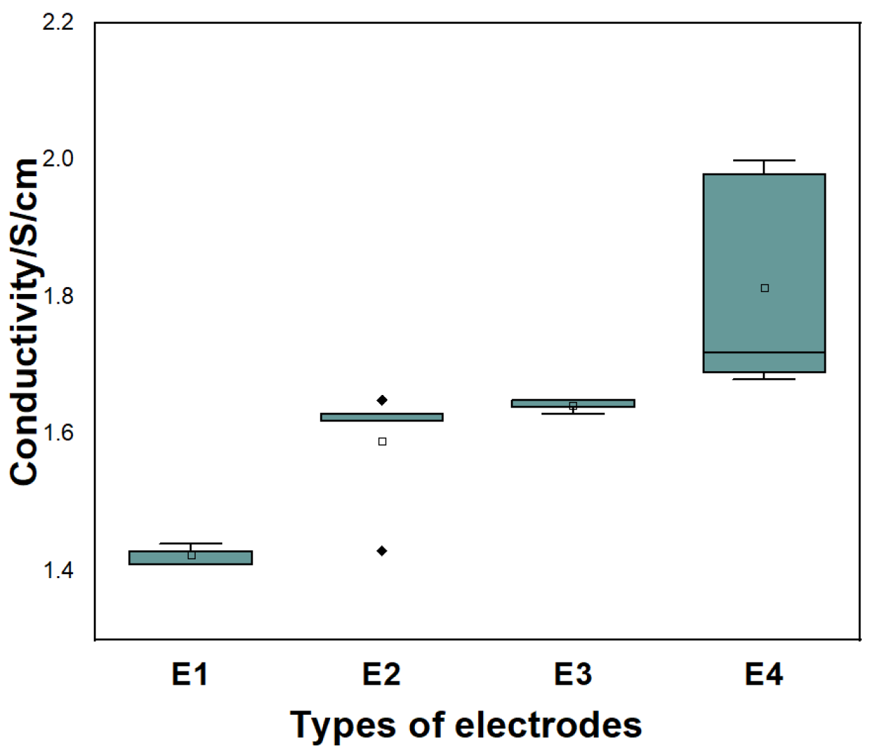
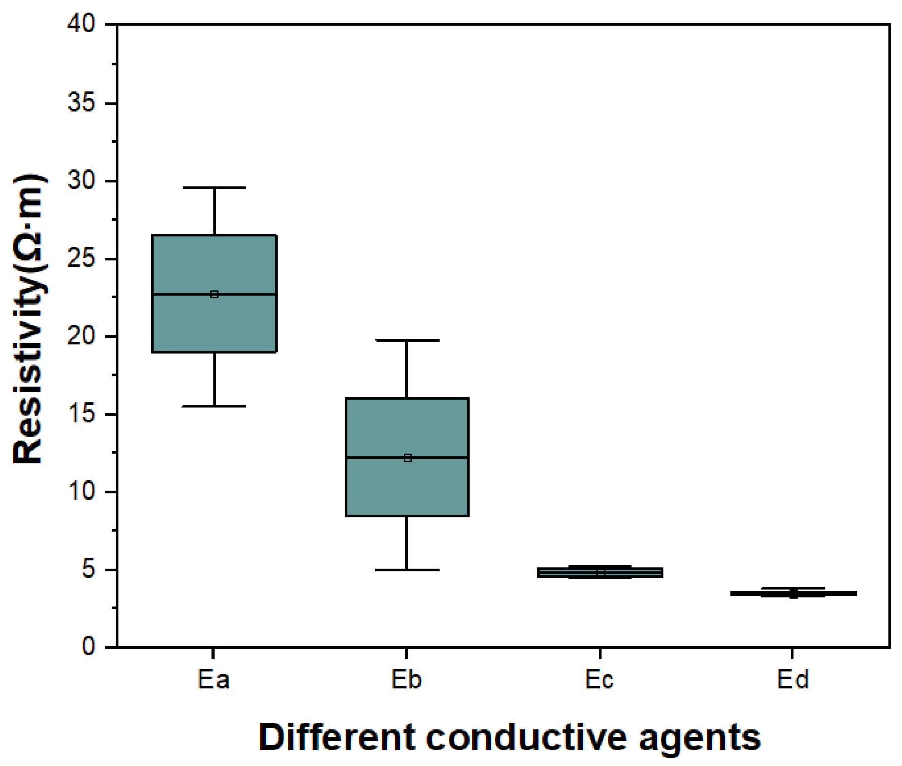
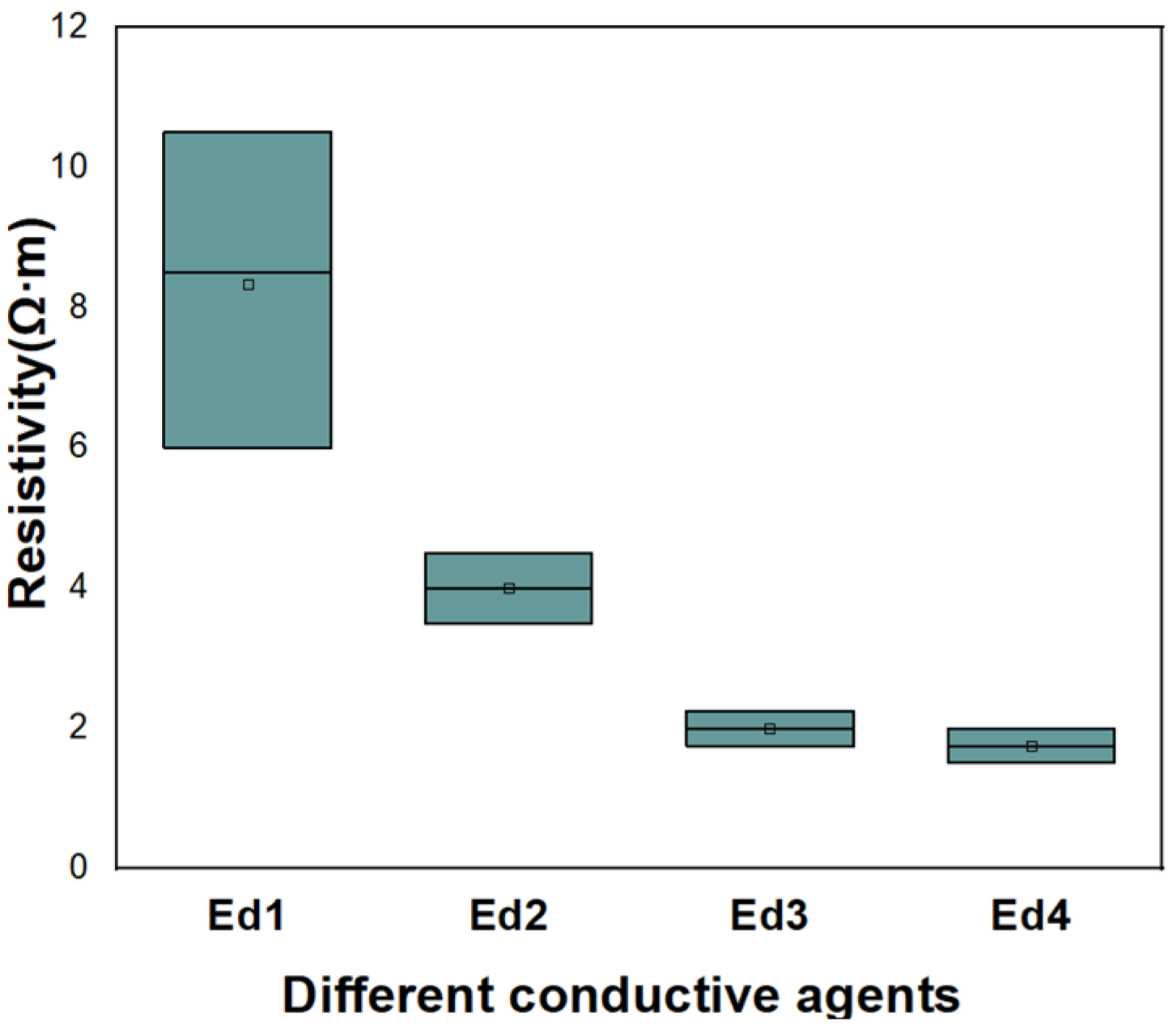
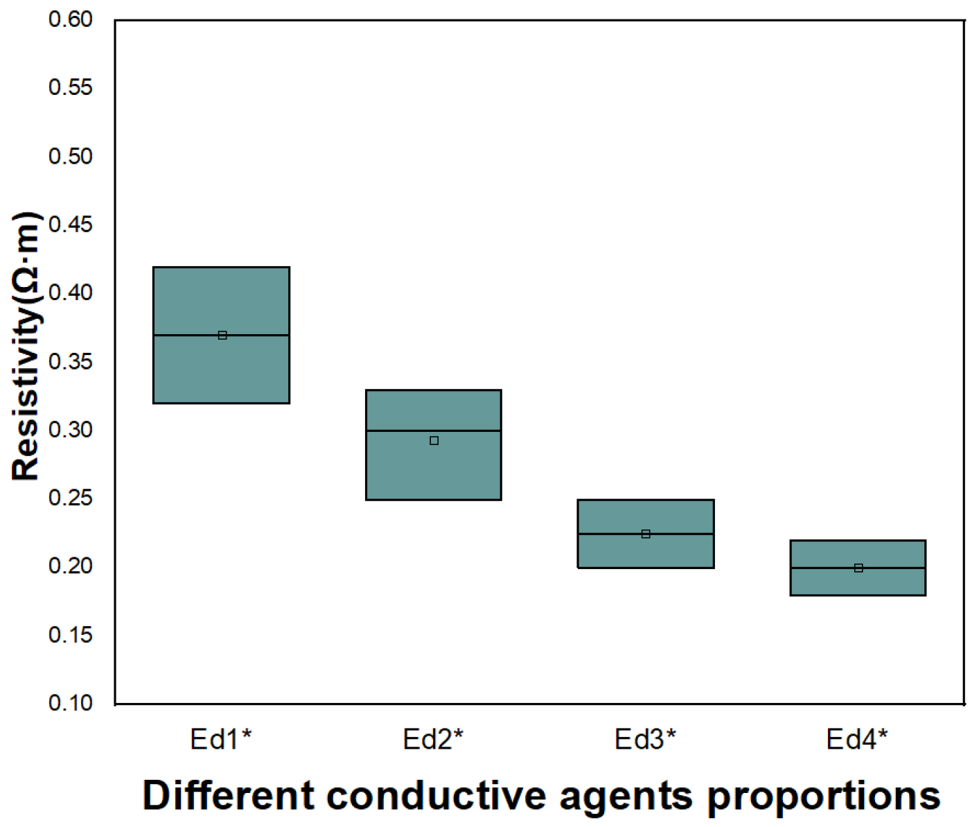
This experiment used four probe technology (RTS-8 four probe tester, Sanuo Instrument Co., Ltd., Shenzhen, China) for conductivity testing on electrode E1 and electrode E2, which prepared from material M1 with large particle size and electrode E3 and electrode E4, which prepared from material M2 with small particle size.
We placed the prepared electrode in the equipment and needed to contact the four probes at each of the four points of the tested object to ensure good contact. At this point, the four probes form a closed circuit that can be tested. Then we start testing, at which point, the four probe tester automatically measured the changes in current and voltage, and calculated the electrical parameters of the tested object.
2.3. Analysis of SEM
Scanning electron microscopy (SEM) is a relatively commonly used method for material characterization. It can use secondary electron signal imaging to observe and analyze the microstructure, morphology, size, and other information of materials. The strength of secondary electrons is closely related to the morphology of the material, thus presenting a good image effect for observation. The magnification of scanning electron microscopy is between optical microscopy and transmission electron microscopy, and the operation is relatively simple, with relatively small requirements for the sample. It can be observed rough and uneven surfaces.
This experiment used TESCAN scanning electron microscope (SunLakes Co., Ltd., Guangdong, China) to study the microstructure of NCM cathode materials and different conductive agents.
2.4. Preparation Process of the Battery
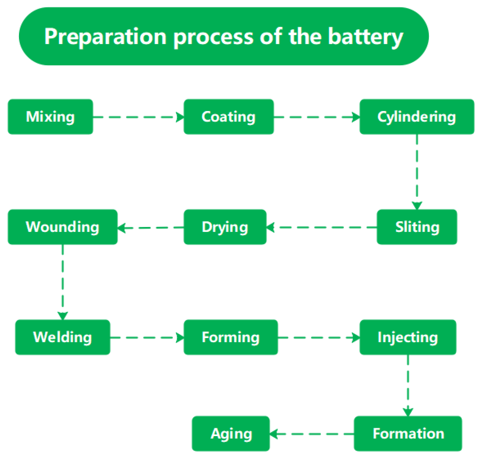
The preparation process of the battery is shown in
Figure 1. In this experiment, small particle NCM (LiNi
xCo
yMn
1−x−yO
2) positive electrode materials with a particle size of 6.0 μm and power type graphite negative electrode materials with a particle size of 6.2 μm, respectively, were mixed with conductive agent (SP, VGCF, CNTs), binder PVDF, and solvent NMP. The mixture was then stirred into a slurry for 5 h. We evenly coated the stirred positive and negative electrode slurries on aluminum foil and copper foil, respectively, and dried them at 120 °C to produce positive and negative electrode plates. The positive electrode coating amount is 22 mg/cm
2, and the negative electrode coating amount is 10 mg/cm
2. Then, the positive and negative electrodes are rolled into electrode pieces with a certain thickness using a rolling equipment. The positive electrode thickness is 80 μm, and the compaction density is 2.5 mg/cm
3. The negative electrode thickness is 85 μm, and the compaction density is 1.17 mg/cm
3. We cut the electrode pieces into a certain length according to the designed capacity. The winding machine winds a certain length of electrode sheet into a cylindrical battery cell. We connect the aluminum and nickel electrode tab to the metal foil and external connection tab through electrode tab welding, and finally package the battery cells into the aluminum battery shell using packaging equipment. We inject high-performance electrolyte with a conductivity of 11.4 m
S/cm into the battery through an injection machine and weld the seal. Formation (using charging and discharging motor) is the process of activating the battery cell through the first charge, during which an effective passivation film (SEI film) is generated on the negative electrode surface to achieve the initialization of the lithium battery. The formation system of this experiment is 0.01C (0.1A) charging for 5 h. Then we used 0.2C (2A) charge the battery to voltage 3.8 V, and then 0.1C (1A) was used to discharge the battery to 2.75 V. Then, we completed battery formation by charging and discharging at 0.1C for four cycles. Finally, a 10 Ah high-power cylindrical battery was prepared for subsequent electrochemical performance testing.
2.5. Electrochemical Performance Testing
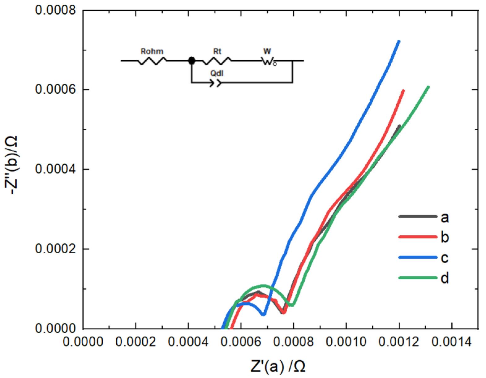
Electrochemical impedance testing is an electrochemical testing method that uses the variation relationship of parameters such as impedance, frequency, phase, and time to obtain information about the possible structure, electrode surface chemical reactions, and other information. This experiment used a CHI660E electrochemical workstation (Xinliyuan Technolngy Co., Ltd., Guangdong, China) to conduct electrochemical impedance testing on the samples before and after coating under the condition of 4.2 V battery charging state. The scanning frequency range was 100 kHz–0.01 Hz from high to low, and the AC voltage amplitude was ±5 mV. After the test was stable, a suitable cyclic impedance spectrum was selected for research and analysis. At the same time, this project uses Z-view software (Version 2.80) to reasonably select and fit the equivalent circuit to calculate the impedance value.
This experiment used CHI660E electrochemical workstation to study the electrochemical impedance of the batters with different electrolyte additives.
The Digatron charge–discharge tester (Realway Electronics Technology Co., Ltd, Shanghai, China) is used to test the electrochemical performance of high-power single cells, such as rate performance, cycling performance, and DC internal resistance. Usually, high-power batteries undergo cyclic testing at a rate of 10C and detect changes in DC internal resistance during the testing process.
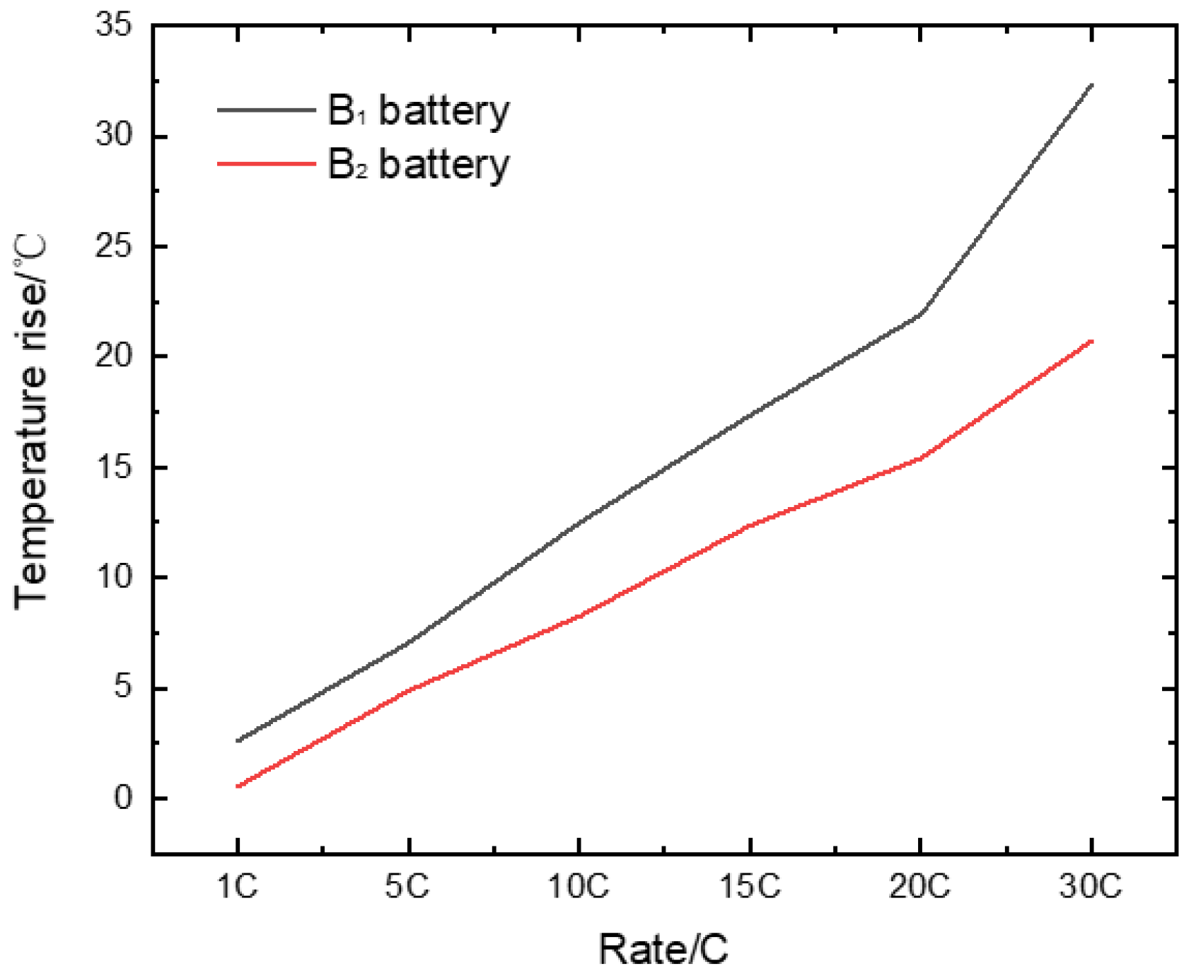
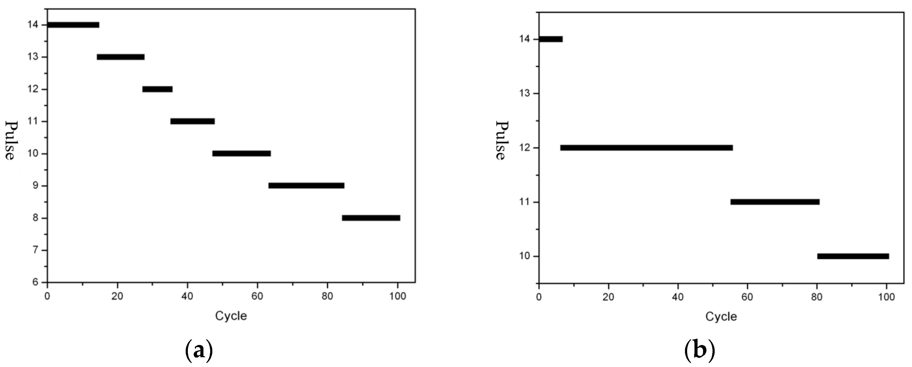
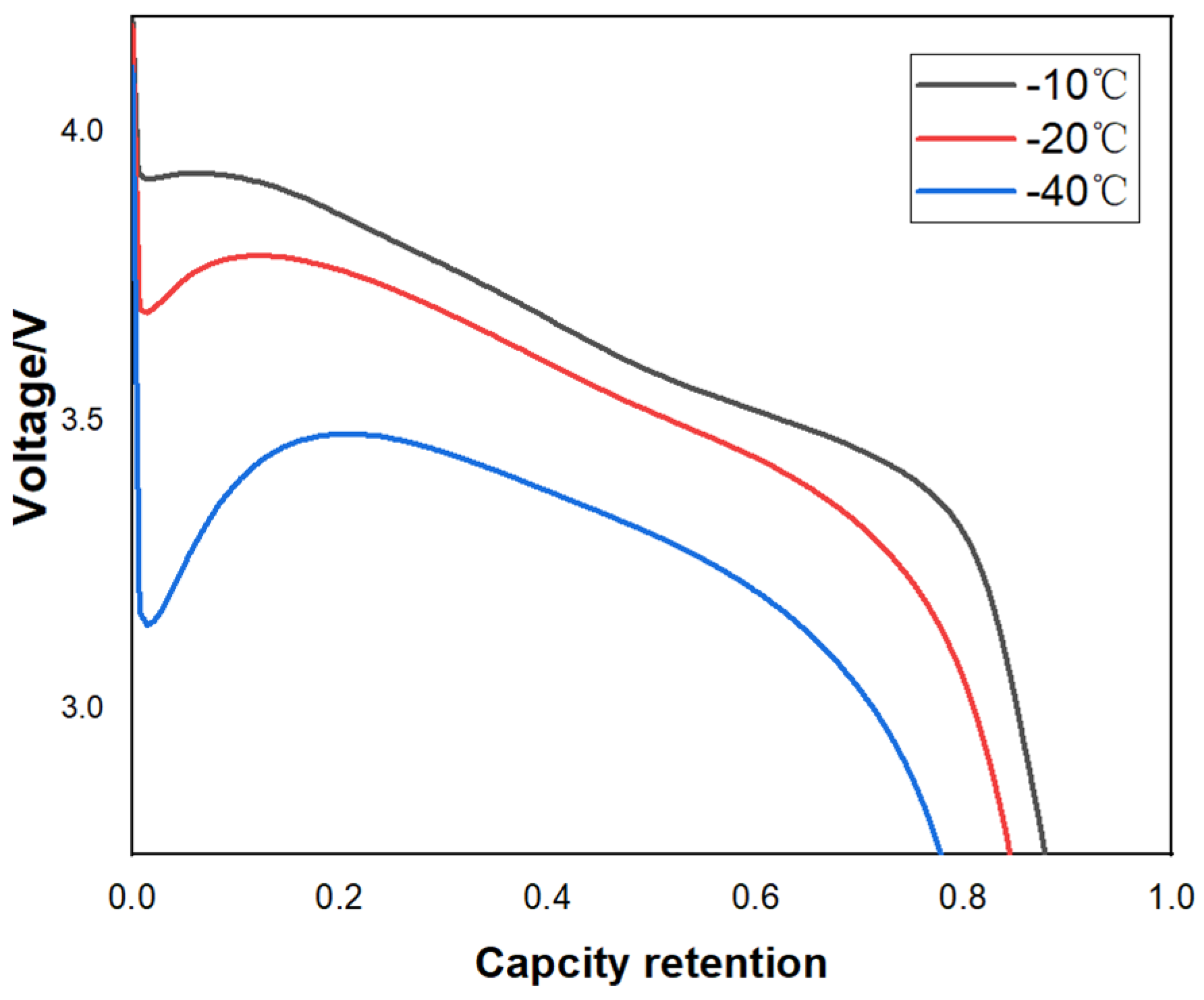
This experiment used a Digatron charging and discharging tester to test the rate performance, specific power, low-temperature performance, and DCIR of the battery. The speed performance test uses 1C (10A) to charge the battery at a constant current of 4.2 V voltage, and then charges the battery at a constant voltage until the current drops to 0.2A. Then, discharges the battery to 2.75 V at different rates of 1C (10A), 10C (100A), 20C (200A), 30C (300A), and 40C (400A). It records the voltage and temperature data during the discharge process. The DCIR test adopts the HPPC internal resistance testing method, using 1C (10A) to charge the battery at a constant current of 4.2 V, and then charges it at a constant voltage until the current drops to 0.2A. Then, uses 1C (10A) to discharge for 10 min. After 60 min, it will discharge at 5C (50A) for 10 s, then charge at 4.5C (45A) for 10 s to complete the HPPC test. By conducting this cyclic test, the internal resistance of the battery can be obtained under different charging states. It calculated the internal resistance of the battery in this charging state using the voltage and discharge current before and after the 10 s discharge process. The low-temperature performance test uses 1C (10A) to charge the battery at a constant current of 4.2 V at 25 °C, and then charges it at a constant voltage until the current drops to 0.2A. Then, it cools to a low temperature environment (−1 °C, −20 °C, −40 °C) and lets it stand for 8 h. We then discharge the battery to 2.75 V using 1C (10A) and record the voltage data during the discharge process. The battery cycling performance test uses 1C (10A) to charge the battery at a constant current of 4.2 V, and then charges the battery at a constant voltage until the current drops to 0.2A. Then, uses 10C (100A) to discharge the battery to 2.75 V. We perform charging and discharging cycles in this way. The specific power test uses 1C (10A) to charge the battery at a constant current of 4.2 V voltage, and then charges the battery at a constant voltage until the current drops to 0.2A. Then, it discharges at 200C (2000A) for 1 s. It records the energy during the discharge process and calculates the specific power. The pulse discharge test uses 1C (10A) to charge the battery at a constant current of 4.2 V, and then charges the battery at a constant voltage until the current drops to 0.2A. Pulse discharge uses a duty cycle of 50C (500A), 400 Hz, and 80%, and conduct charging and discharging cycles in this way.
3. Research on Improving the Power Performance of Lithium-Ion Batteries
The main methods to improve the power performance of batteries are currently to increase the working voltage of active materials and reduce the internal resistance of batteries. The low impedance design can be achieved by shortening the lithium-ion transport distance, increasing the conductivity rate, and achieving high-performance interfaces. Reducing material particle size is an effective way to shorten the distance of lithium-ion transport. Establishing an efficient conductive network, increasing bulk diffusion rate, and increasing ion conductivity are good ways to improve conductivity. A good SEI film is beneficial for improving the interface performance between materials and electrolytes [
21]. This article aims to improve the rate performance of batteries by studying high-performance cathode materials, excellent conductive networks, and high-performance electrolytes.
3.1. Analysis of High-Performance Cathode Materials
High-nickel materials are currently the mainstream high-capacity cathode materials. At present, the NCM system cathode materials mainly include NCA (LiNixCoyAl1−x−yO2) and NCM (LiNixCoyMn1−x−yO2) systems. The current product models of NCM materials range from 333 (Ni: Co: Mn) to 442, 532, 622, and 811. With the increase of nickel content, the energy density of the battery is also increased.
Table 1 shows the performance parameters of NCM cathode materials. The maximum specific capacity of six series of NCM materials can reach 190 mAh/g. The NCM material 811 with high nickel content can reach 200~210 mAh/g (4.3 V vs. Li/Li
+). According to the further analysis of the high-nickel 811 material with higher capacity, the mainstream products in the market are mainly polycrystalline, which is formed by the agglomeration of 200~300 nm primary particles, and manufacturers in China have mastered their processing and preparation technologies and are promoting them on a large scale [
22]. However, with the increase of nickel content, the cation mixing in the material and the structure transformation are intensified during the charging and discharging process. At the same time, the anisotropy of the primary particles expands during the charging and discharging process, resulting in cracks in the secondary particles, which affects the cycle performance of the battery. In addition, problems such as battery gas generation, high residual alkali content at the interface and thermal effect will also occur at the interface of electrode materials. At present, the modification and interface modification technologies for high-nickel NCM materials are relatively mature and complete, mainly including body optimization, structure control, interface modification, etc. The body optimization includes controlling the size of primary particles, optimizing the composition, or adjusting the polycrystalline materials into single crystal materials to reduce the specific surface area. The structure control is mainly through the bulk doping technology, and the structure of the material is improved by the anion and cation doping. Interface modification is the main method of modification of high-nickel materials at present, and surface coating is a good modification method [
23].
With the rise of the voltage platform of medium-nickel materials, the performance of the energy density of the high-voltage route tends to be consistent with that of the high-nickel NCM. The high-voltage route makes the cathode material release more lithium ions at a higher voltage by raising the battery charging cut-off voltage, thus improving the capacity and working voltage, and thus achieving the purpose of improving the energy density. In addition,
Table 2 shows the comparison of performance parameters between single crystal and polycrystalline materials. The single crystal cathode material can enhance the single-grain size of the cathode material on the basis of maintaining the existing capacity and charging and discharging platform, so as to scale up its compaction density, improve the volume capacity of the battery, and greatly increase the safety of the lithium battery, to greatly improve the performance of the battery [
24,
25,
26]. The physical and chemical properties of monocrystalline materials are more stable. Compared with polycrystalline materials, monocrystalline materials have good safety and cycling performance, which can avoid the problems of poor structural stability and particle pulverization during the high-temperature cycling of polycrystalline materials. But single crystal materials have a larger particle size, making it more difficult for lithium-ion diffusion. Therefore, when charging and discharging within the same voltage range, the discharge-specific capacity of single crystal materials is lower, and the capacity performance is not as good as that of polycrystalline materials. Therefore, when designing the electrochemical system of high-power batteries, more small particle polycrystalline materials are used to improve the rate performance of the battery.
NCA material belongs to the high nickel system (nickel content reaches more than 80%). The specific capacity of this material can reach 180~190 mAh/g at 4.2 V. It has been applied in batches in the civil market (such as the 18,650 high energy battery provided by Panasonic for Tesla) [
27,
28]. It is the battery system with the highest specific energy in the civil market at present. NCA material has been successfully applied outside China due to its excellent life characteristics and high energy density. Due to the high alkali content on the surface of the material, the requirements for the subsequent battery processing and preparation process are harsh, and it needs to be fully explored and demonstrated from the aspects of environment, process control, equipment technology, and process technology.
The discharge capacity of a high-power battery depends on the migration of lithium ion in the electrolyte and the diffusion rate in the solid phase. The pulsed discharge capacity more depends on the lithium-ion migration and diffusion on the surface of the active material [
29]. Increasing the surface area of the active material will greatly improve the high-rate discharge capacity of the battery.
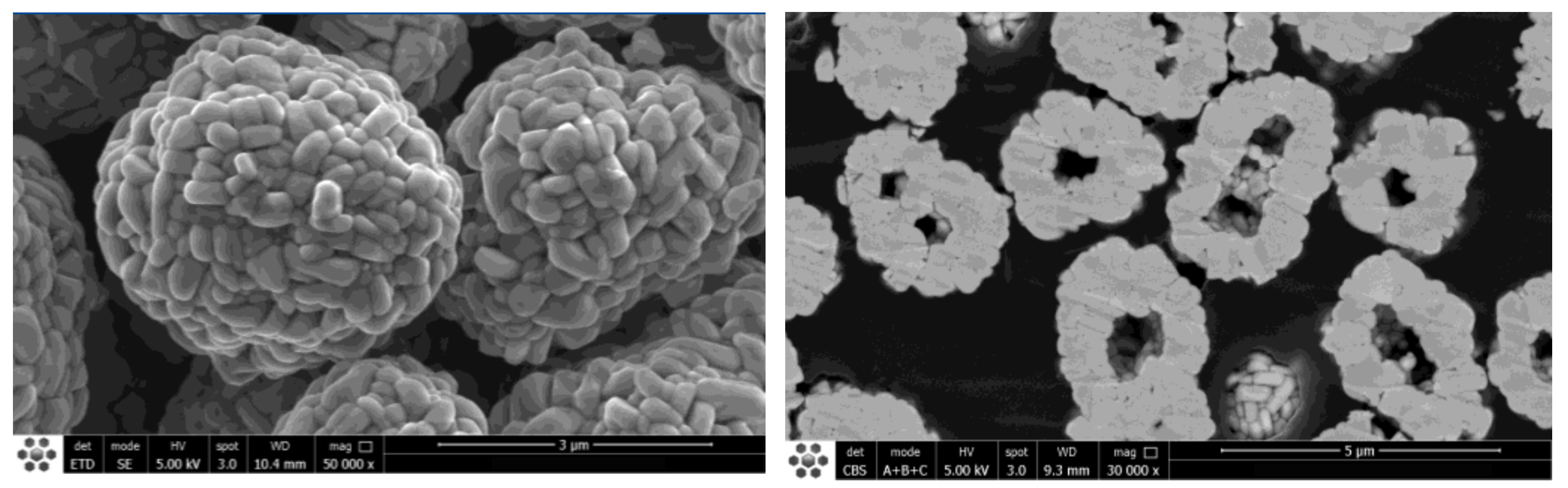
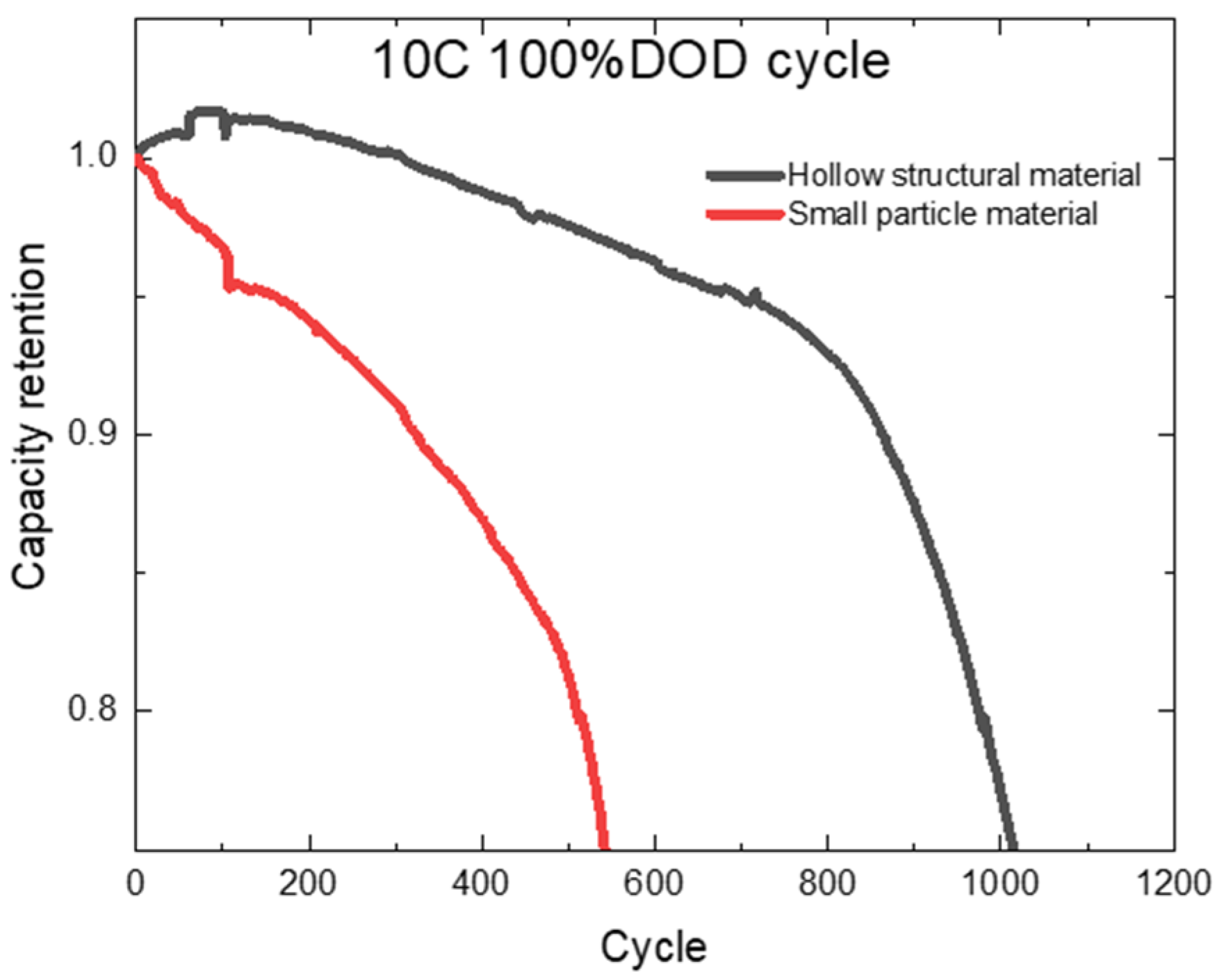
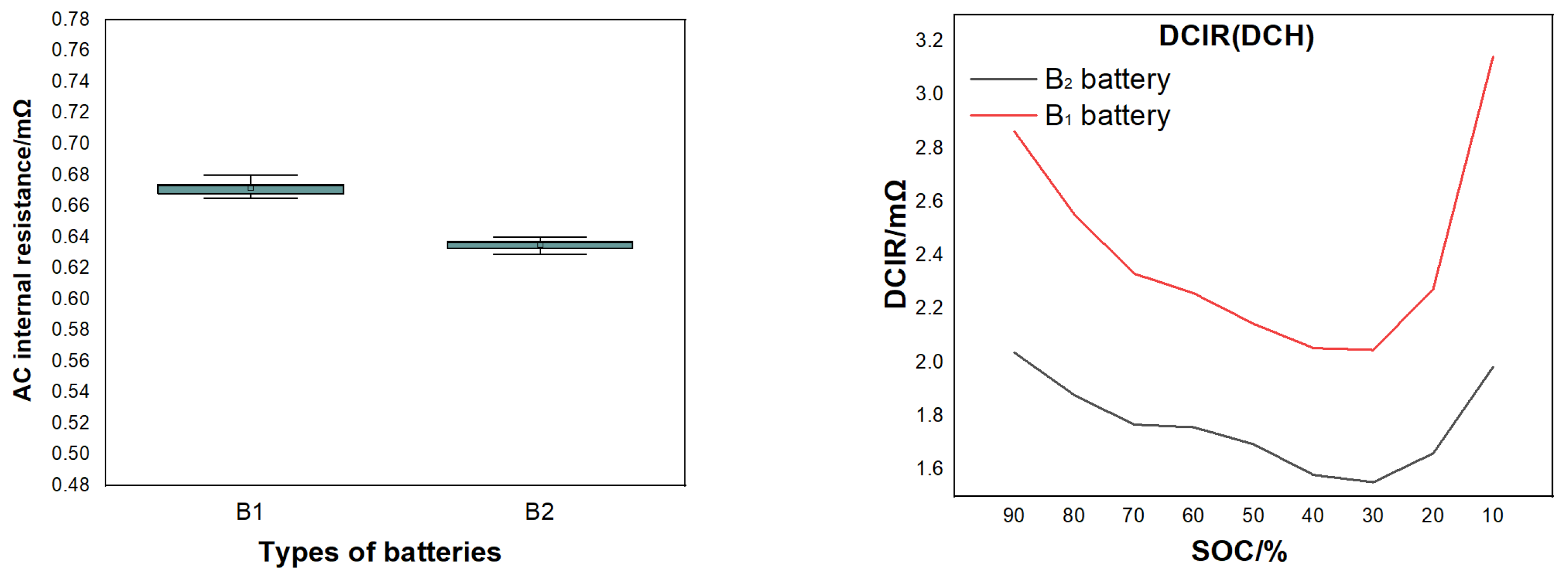
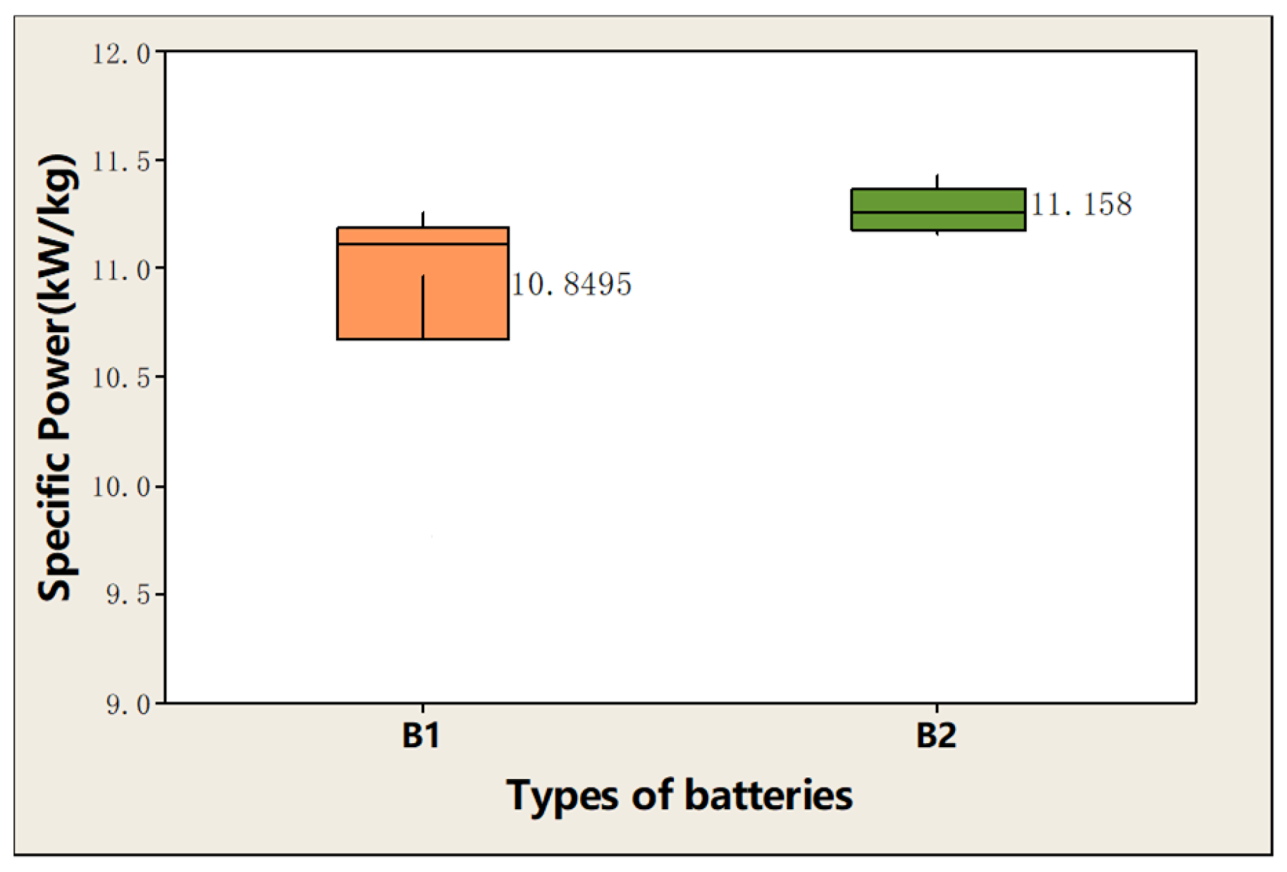
The research shows that small particle size materials can obtain higher specific power and lower AC internal resistance, and finally get better rate performance. However, blindly reducing the particle size will lead to a too-large specific surface area of the material and increase the interfacial side reaction. Therefore, we chose the hollow structure of small particle cathode material as shown in
Figure 2. The particle size is between 2~4 μm.
To sum up, the high-nickel NCM cathode material has higher energy density, good magnification performance, rich modification and modification methods, and relatively mature production process. At the same time, the manufacturer is more stable for long-term supply, so it is more suitable for special applications.
3.2. Establishment of High-Performance Conductive Network
In the rate electrode system, low-resistance design is required, so the type and content of conductive agent and binder need to be screened and optimized to improve the electronic conductivity and ionic conductivity of the electrode. The electronic resistance can be reduced by optimizing the conductive network formed by the conductive agent, and the ionic resistance can be reduced by adding an appropriate amount of ionic conductive agent to form the ionic conductive network. At the same time, the project also has certain energy density requirements, so it is particularly important to strictly control the content of conductive agent [
30].
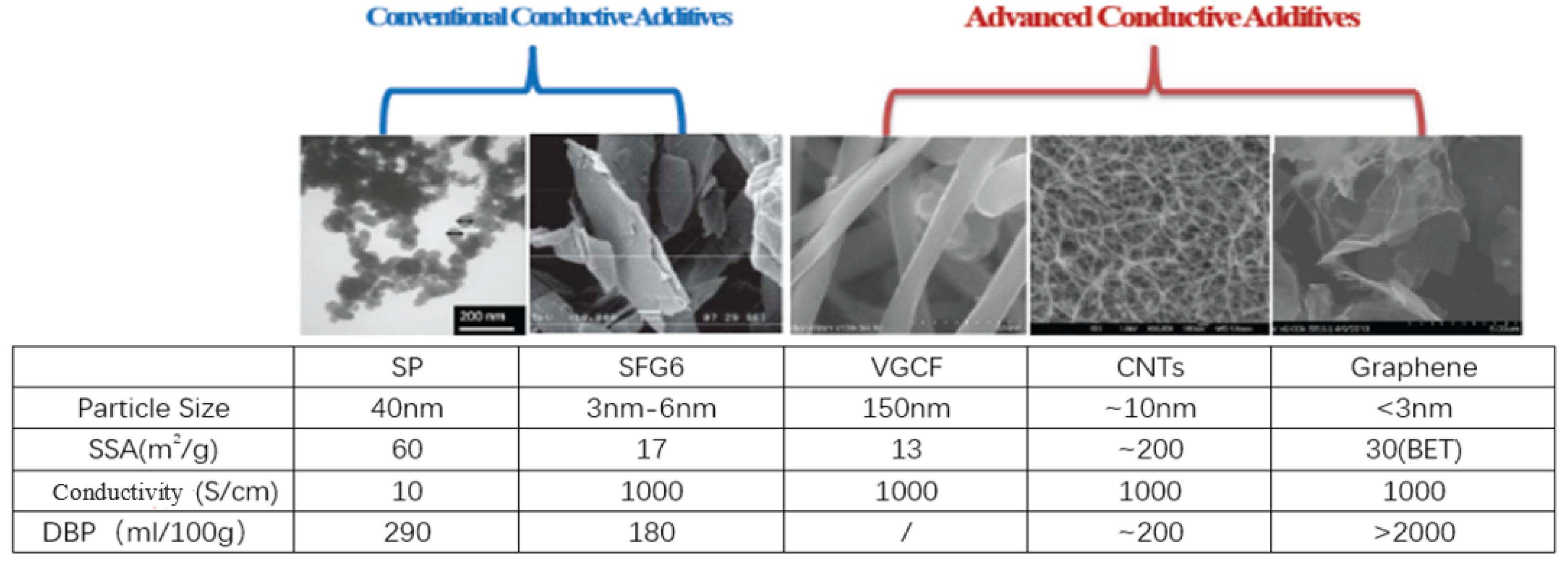
Figure 3 shows the schematic diagram of different conductive agents. Compared with traditional conductive agents, carbon nanotube (CNT) has a longer pipe diameter and can be in close contact with active materials to effectively build a nanoscale conductive network, effectively improve the long-term conductivity of the electrode, reduce the use of conductive agents, and improve the power performance of the battery.
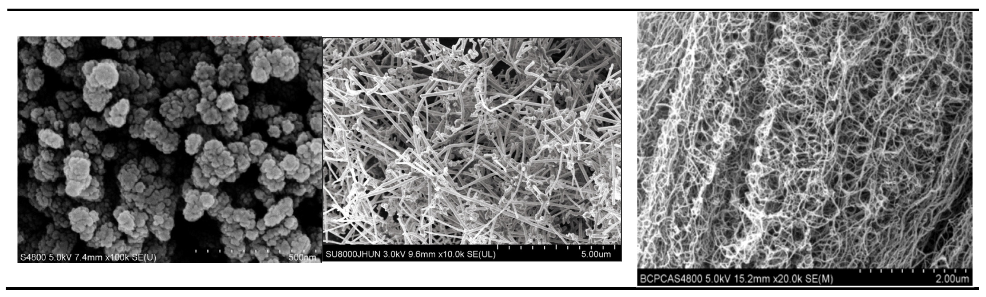
For the electrode, materials with poor conductivity, especially the cathode materials, the role of the conductive agent is to form a conductive network to connect the active material particles and provide a fast electron transfer channel. Conductive networks have a very important impact on the performance of lithium-ion batteries [
32]. Conductive agents mainly include carbon black, carbon fiber, and carbon nanotubes;
Figure 4 shows SEM photos of three different types of conductive agents. These three materials have their own advantages in three-dimensional conductivity, so we have studied their best combination and dosage.
The conductive path formed by a traditional conductive agent is single, and the conductive ability is relatively poor. The new type of conductive agent has good conductivity, but it is difficult to disperse. Therefore, it is an important means to improve the conductivity of the electrode system by using multiple composite conductive agents to achieve complementary advantages. Generally, the ion conduction of the low-rate discharge electrode mainly depends on the ion exchange between the electrode material itself and the electrolyte. The relatively high ion impedance will seriously affect the high-rate discharge performance. This project uses high-rate discharge, so it is necessary to add additional ionic conductive agent to reduce its ionic impedance. By optimizing the type and dosage of ionic conductive agent, the ionic conductive network is constructed, and the relationship between its high-rate discharge performance and the type and dosage of ionic conductive agent is studied, so as to prepare the high-performance ion-electronic conductive network.
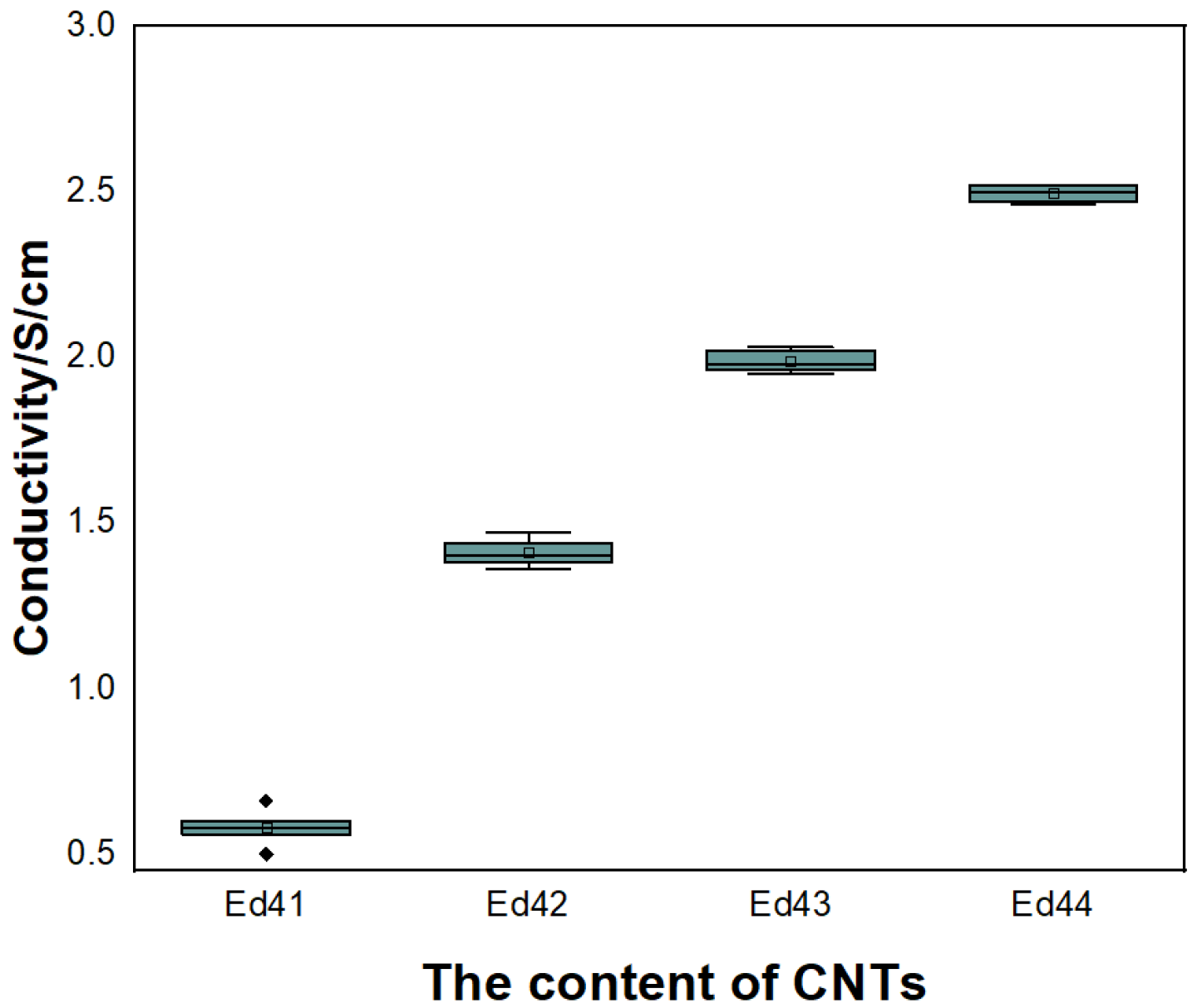
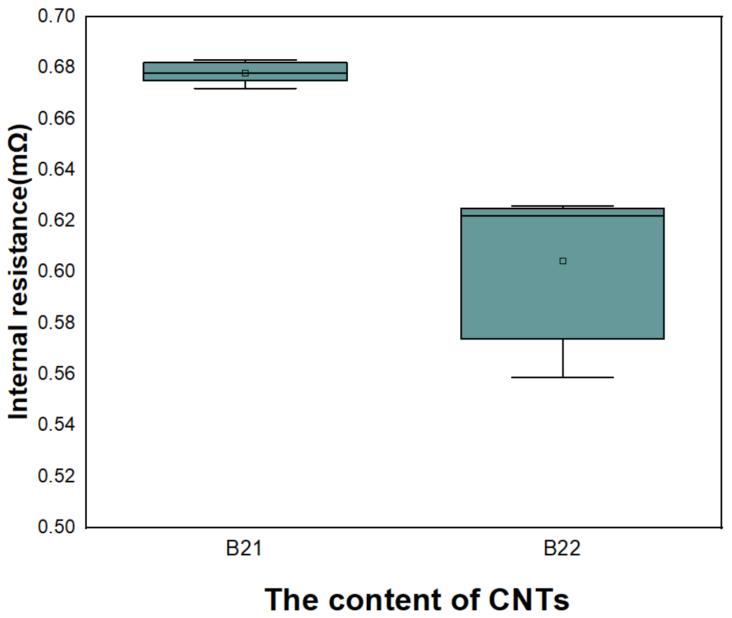
The project realizes the construction of a multi-dimensional composite conductive network from point to line, and from small to large size, through the mixed use of conductive carbon black, carbon fiber, and carbon nanotube, which greatly reduces the contact resistance between active material particles. At the same time, by optimizing the adding method and composition proportion of the composite conductive agent, a short-range, medium-range and long-distance three-dimensional conductive network is built inside the electrode, which greatly reduces the amount of conductive agent while improving the electrode conductivity. The relationship between the ratio of conductive agent and the ratio performance is studied by testing the ratio performance of the battery, and the low-temperature discharge capacity of different ratios of conductive agent is studied by testing the low-temperature performance of the battery, so as to optimize the ratio of conductive agent suitable for high-rate discharge and the composite conductive agent with excellent low-temperature discharge capacity [
33]. Finally, we established a new type of conductive network.
3.3. Research on High-Performance Electrolyte
Electrolyte has a very important impact on the performance of the battery, especially high and low temperature, and cycle performance. In view of the problem that the increase of the viscosity of the electrolyte at low temperature leads to the decrease of conductivity, the decrease of Li
+ diffusion rate and the increase of charge transfer impedance at the interface of the electrolyte, researchers have carried out many optimization studies on the low-temperature performance of the electrolyte, most of which are aimed at the modification of the electrolyte by the solvent, lithium salt, and additives in the electrolyte. Generally, the electrolyte of the ion battery is a mixture of different kinds of organic solvents such as carbonates and carboxylates. There are high melting point solvents in the mixed solvent. At low temperature, the viscosity of the electrolyte of the lithium-ion battery increases, the conductivity of the solvent decreases with the decrease of temperature, and the internal resistance of the lithium-ion battery increases. When the temperature is too low, the electrolyte will solidify, resulting in the reduction of the transmission rate of lithium ions in the electrolyte [
34,
35].
The requirements of low-temperature electrolyte for solvent are mainly as follows: high dielectric constant, low viscosity, low melting point, stable SEI film formed by reaction with electrode, and high solubility of lithium salt. In order to better improve the low-temperature performance of lithium-ion batteries, researchers often use a mixed system of multiple solvents. Ethylene carbonate (EC) is the main solvent component of the electrolyte, but its melting point is high, and its solubility in the electrolyte is reduced or even precipitated at low temperature, which has a negative impact on the low-temperature performance of the battery. By adding components with low melting point and low viscosity, the viscosity and co-melting point of the electrolyte at low temperature can be effectively reduced, thus reducing the impedance of lithium-ion battery at low-temperature discharge and improving its discharge performance. The physical ion battery with EC- dimethyl carbonate (DMC)- ethyl acetate (EA)/EC-DMC- methylene blue (MB) as a solvent can still maintain 80% of the capacity at room temperature at −40 °C. The capacity of a lithium-ion battery with propylene carbonate (PC)-EC-MB as a solvent can reach 95% of normal temperature capacity at −30 °C. The theoretical melting point of the electrolyte can reach −91 °C with EA as the cosolvent and LiTFSI as the electrolyte salt. In addition, the amorphous electrolyte is obtained by mixing EC and poly(ethylene glycol) dimethyl ether (PEG250). At −60 °C, its conductivity can still reach 0.014 mS·cm−1, greatly improving the performance of the electrolyte at low temperature.
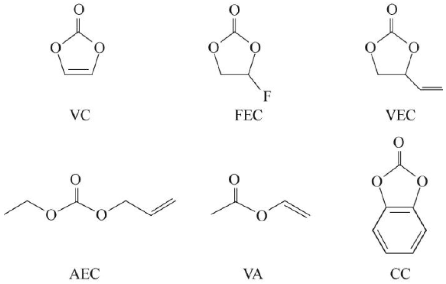
The excellent SEI film and CEI film allow lithium ions to pass freely, and the solvent and other components cannot pass through, preventing the further reaction of positive, negative, and electrolyte, and improving the comprehensive performance of the battery. The film-forming additive is a kind of material that can preferentially take place oxidation-reduction reaction at the positive and negative electrode interface during the first charge and discharge process to form excellent CEI and SEI films.
Figure 5 shows molecular structure of common unsaturated ester additives.
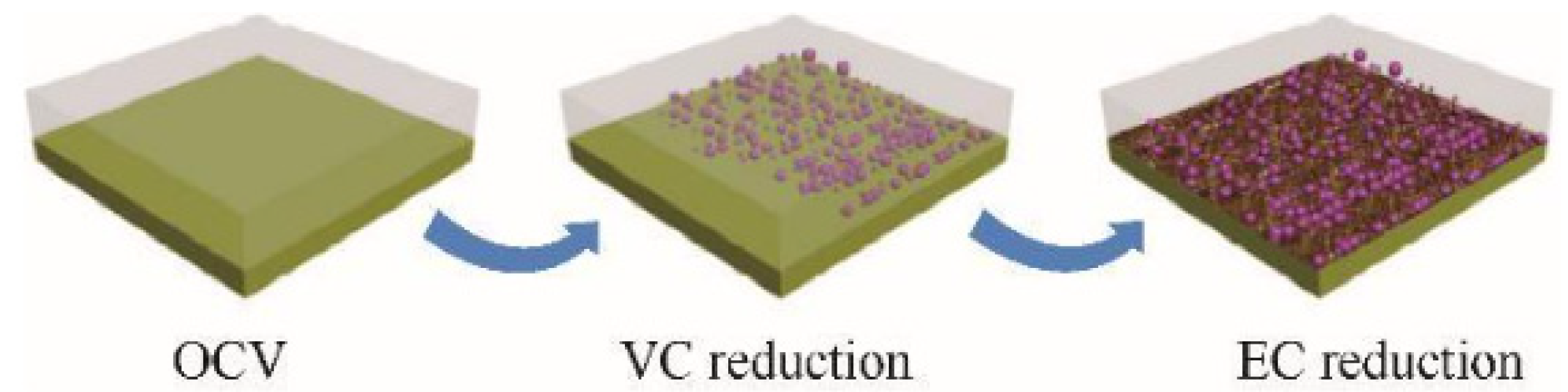
The film-forming mechanism of VC is that it can preferentially reduce compared to the electrolyte, thus allowing for the formation of SEI films. Lin et al. [
37] found that 1% VC in the electrolyte can promote the formation of initial SEI at higher potentials and inhibit the reduction of EC, as shown in
Figure 6. VC first undergoes a reduction reaction and forms many particles on the HOPG surface. The subsequent EC reduction helps to form a thin layer on the uncovered HOPG surface. Guo et al. [
38] evaluated an ionic liquid-based mixed electrolyte system with EC/PC as the cosolvent and VC as the additive. The results indicate that the presence of VC can form SEI at the electrode interface, preventing the reduction and decomposition of EC. SEI also promotes the effective insertion of Li
+ into graphite.
Due to the lower unoccupied orbital of FEC compared to most electrolyte solvents, it can be preferentially reduced and decomposed on the negative electrode, making it a good negative electrode film-forming additive. Recent articles have also reported that FEC molecules can act as a mediator to unify the orientation of solvent molecules at the negative electrode interface. This way of rearranging solvent molecules on the negative electrode surface may be beneficial for regenerating SEI films with better performance.
In the end, we chose an electrolyte salt mainly composed of LiPF6 and supplemented by LiTFSI, with EC and DMC as the main solvents, and high-performance film-forming additives (FEC, VC) added as the electrolyte for high-power batteries.
5. Conclusions
This article investigates methods for improving battery power performance from the perspective of electrochemical systems.
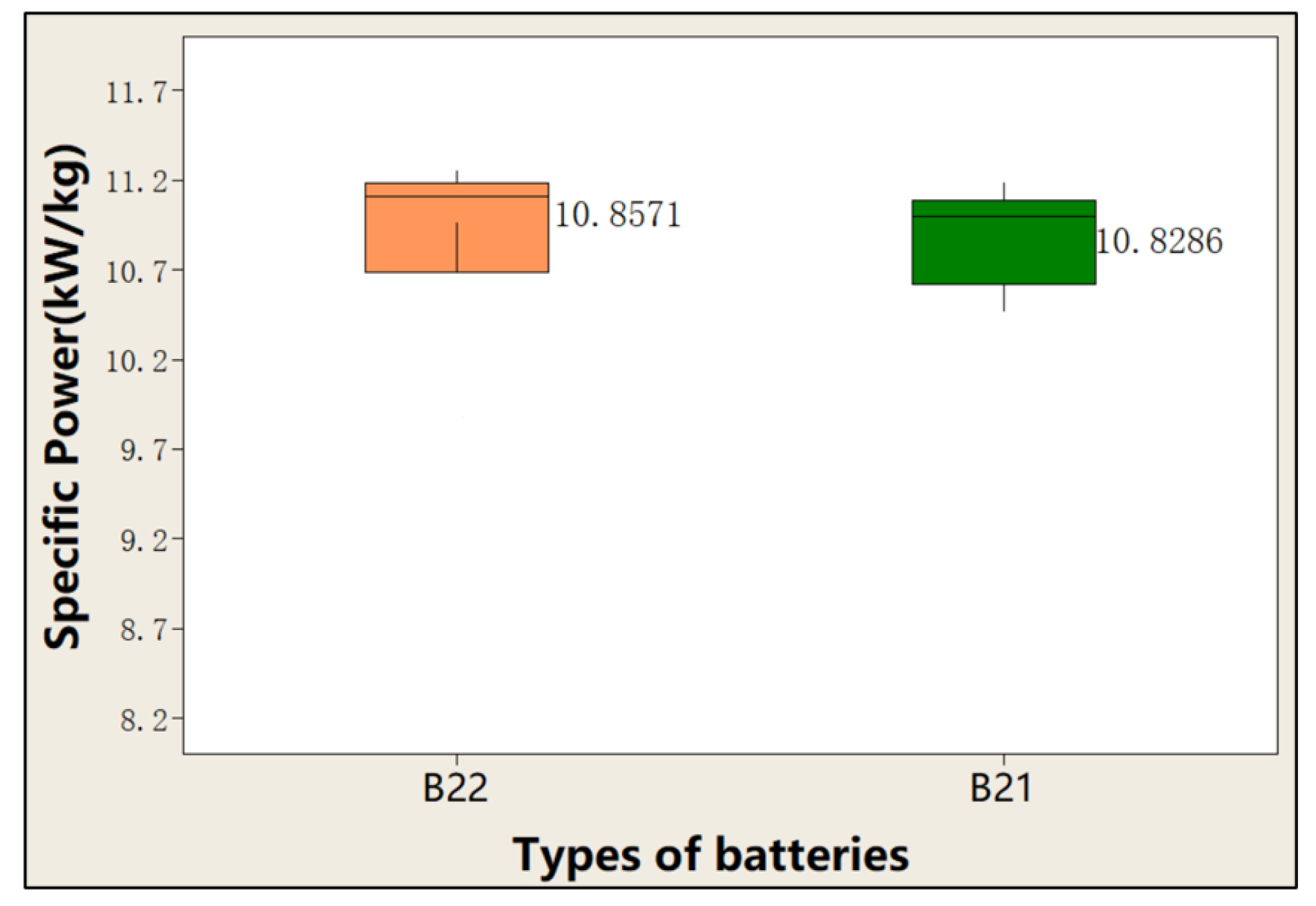
Firstly, the structure of high-performance cathode materials was optimized by selecting NCM materials with small particle hollow structures, which effectively shortened the lithium-ion transport distance. The results show that batteries prepared with small particle NCM have lower internal resistance, with a DCIR of only 2 mΩ, and have greater rate performance; the 40C discharge capacity retention rate exceeds 95%, and the specific power can reach 11.5 kw/kg. Then, by establishing a new and efficient conductive network, the ion conductivity inside the battery was increased. The electrode with SP, VGCF, and CNTs mixed conductive agents which can effectively improve the performance of the conductive network. The results show that electrodes prepared with new conductive agents have lower surface resistance (0.2 Ω·cm) and higher conductivity (2 S/cm). Using high-performance film-forming additives can improve the interface performance of electrodes and electrolytes. The battery with additives FEC + DTD can achieve smaller SEI film impedance and meet the requirements of high-power pulse discharge. Meanwhile, by optimizing the solvent structure and adding PC and EA, the battery can achieve good low-temperature performance, and the discharge capacity retention rate at −40 °C is still greater than 80%.
In addition, a 10 Ah cylindrical high-power lithium-ion battery is manufactured. The specific energy of the battery reaches 110 Wh/kg, the specific power of the second pulse reaches 11.3 kW/kg, and the AC internal resistance of the battery is less than 0.7 m Ω. The battery has continuous discharge capacity of 10C~30C and pulse discharge capacity of more than 100C. The number of full-capacity discharge cycles at 10C is more than 1700, and the number of full-capacity discharge cycles at 30C is more than 500, which has wide application value in the field of new equipment.


