Article

Thermodynamic Analysis of a Cogeneration System Combined with Heat, Cold, and Electricity Based on the Supercritical CO2 Power Cycle

School of Mechanical and Electrical Engineering, Qingdao University, Qingdao 266071, China
*
Author to whom correspondence should be addressed.
Energies 2024, 17(7), 1767; https://doi.org/10.3390/en17071767
Submission received: 6 March 2024 / Revised: 30 March 2024 / Accepted: 2 April 2024 / Published: 8 April 2024
(This article belongs to the Special Issue Advances in Solar Systems and Energy Efficiency)

Abstract

:
The supercritical CO2 power cycle driven by solar as a new generation of solar thermal power generation technology has drawn significant attention worldwide. In this paper, a cogeneration system derived from a supercritical CO2 recompression Brayton cycle is proposed, by considering the recovery of waste heat from the turbine outlet. The absorption refrigeration cycle is powered by the medium-temperature waste heat from the turbine outlet, while the low-temperature waste heat is employed for heating, achieving the cascaded utilization of the heat from the turbine outlet. As for the proposed combined cooling, heating, and power (CCHP) system, a dynamic model was built and verified in MATLAB R2021b/Simulink. Under design conditions, values for the energy utilization factor (EUF) and exergy efficiency of the cogeneration system were obtained. Moreover, the thermodynamic performances of the system were investigated in variable cooling/heating load and irradiation conditions. Compared with the reference system, it is indicated that the energy utilization factor (EUF) and exergy efficiency are 84.7% and 64.8%, which are improved by 11.5% and 10.3%. The proposed supercritical CO2 CCHP system offers an effective solution for the efficient utilization of solar energy.

1. Introduction

The consumption of fossil fuels causes energy shortages, environmental pollution, and global warming, and the utilization of sustainable energy attracts widespread attention; solar energy is one of the ideal renewable energies because of its abundant reserves and wide distribution [1]. Solar tower thermal power generation is considered to be a promising way due to its advantages of high efficiency of photothermal conversion, high flexibility of heat storage, and strong scalability of power generation [2]. Considering the characteristics of compactness and high system efficiency, the integration of concentrated solar energy with a S-CO2 power cycle has the potential to enhance the overall efficiency of solar conversion.
In the traditional coal power generation systems, there are problems of relatively high emissions and relatively low thermal efficiency. Therefore, it is necessary to adopt new clean technologies which reduces gas emissions and improve energy conversion efficiency [3].
The S-CO2 (supercritical CO2) Brayton cycle is mainly divided into simple cycle, recompression cycle (SCRBC), partial cooling cycle, intercooling cycle, pre-compression cycle, and improved cycle on this basis. The simple supercritical CO2 Brayton cycle (SCBC) has the disadvantages of excessive waste heat and low efficiency. The simple regenerative cycle is formed by increasing a recuperation component, but the simple regenerative cycle has low efficiency because of the existence of a pinch point. In order to avoid the pinch point, a high-temperature regenerator and a low-temperature regenerator are added, and the recompression cycle is proposed. In order to improve cycle efficiency, two-stage compression and intermediate cooling is added in the main compression loop, and a cooler is added in the recompression loop, which form the intermediate cooling cycle and partial cooling cycle [4,5,6,7]. Moreover, compared with the traditional water-steam Rankine cycle, the system thermal efficiency of the supercritical CO2 Brayton cycle is higher when the turbine inlet temperature is higher than 550 °C [8]. In addition, the supercritical CO2 Brayton cycle, especially the supercritical CO2 recompression Brayton cycle (SCRBC), has a higher thermal efficiency in the concentrated solar power (CSP) temperature range compared to the steam Rankine cycle [9].
In order to explore thermodynamic performances of supercritical CO2 Brayton cycles, simulation studies of different Brayton cycles have been conducted, and the thermodynamic performances have been compared. Turchi et al. [10] analyzed four different arrangements of supercritical CO2 Brayton cycles to study the effects of reheating and air cooling on the supercritical CO2 cycle performance in a CSP system, and found that when the turbine inlet temperature exceeded 650 °C, the thermal efficiency values of the partial cooling, recompression, and intermediate cooling cycles were almost about 50.0%. Mahmood et al. [11] used genetic algorithms to perform thermodynamic optimization and comparative analysis on different cycles; the conclusion was that the highest cycle efficiency is the reheat and intermediate cooling cycle based on recompression, with a cycle efficiency of 55.0–62.0%. Ortega et al. [12] developed an S-CO2 Brayton cycle model using EES (Engineering Equation Solver); it was found that within a certain range of pressure ratios yields, the highest efficiency in terms of the first law of thermodynamics occurred in the SCRBC. Zhang et al. [13] studied several Brayton cycles when the inlet temperature of the turbine varied from 500 °C to 850 °C, and found that the optimal efficiency for the recompression Brayton cycle occurs when the inlet temperature falls between 500 °C and 600 °C. Neises et al. [14] pointed out that when applied to a CSP system, the system performance of the steam cycle is lower than that of the SCRBC. The 780 kW supercritical CO2 Brayton cycle power system, developed by Sandia National Nuclear Laboratories and the U.S. Department of Energy’s Office of Nuclear Energy [15], is one of the first Brayton supercritical CO2 cycle power systems in operation in the world. Knolls and Bettis Atomic Energy Laboratory [16] jointly developed a 100 kW biaxial reheat supercritical CO2 power cycle experimental platform to test the system performance under variable operating conditions; the results showed that the system could operate well. Seidel [17] investigated the efficiency of several cycles coupled with Concentrated Solar Power systems and determined that the SCRBC exhibits superior thermal efficiency across a wide range of pressure ratios.
In order to improve the thermodynamic performance of SCBC, investigations have been conducted by integrating supercritical CO2 cycle with other cycles. Wang et al. [18] proposed two combined cycles, which hybridized the simple and recompressed Brayton cycles with the transcritical CO2 cycles; the investigations revealed that the combined cycles demonstrated a significant enhancement in efficiencies, with improvements of 10.12% and 19.34% compared to the simple and recompressed Brayton cycles, respectively.
NR Caetano et al. [19] conducted energy and exergy analyses between combined Brayton/Rankine cycles with two regenerators in parallel and conventional combined Brayton/Rankine cycles. The results showed that thermal efficiency of the combined cycle with two regenerators was increased by 36.7%, and the exergy destruction of the exhaust gases and condenser was reduced by 80.7% and 31.2%, respectively. Moreover, by combining the Rankine cycle with the supercritical CO2 cycle, a combined cycle is formed, as demonstrated by Akbari et al. [20]; the exergy efficiency of the proposed SCRBC/ORC (Organic Rankine Cycle) combined cycle increased by 11.7% compared with that of SCRBC. The thermal efficiency of the combined system proposed by Liang et al. [9] was 3.5% higher than that of the recompressed Brayton cycle system. The maximum output power of the combined system proposed by Song et al. [21] is 58.0% higher than that of the independent supercritical CO2 Brayton system. Not only is the recompressing Brayton cycle coupling with the Rankine cycle proposed, but also other Brayton cycles coupling with the Rankine cycle are analyzed. A combined cycle system integrating GTC, the supercritical CO2 Brayton ARC cycle, and the organic Rankine cycle are proposed by Wang et al. [22]; the research outcomes indicate that the system has a superior thermodynamic performance to that of the cogeneration system. Pan et al. [23] compared four combined systems and found that the combined cycle of the supercritical CO2 recompression Brayton cycle with ORC has the most superior performance. A supercritical CO2 power cycle cogeneration system developed by Yang et al. [24] was optimized with multiple objectives. The optimization results indicate that the comprehensive performance index of the proposed cycle is higher than that of the traditional cogeneration cycle system. According to Yari et al. [25], in which a study was conducted on a hybrid system integrating a supercritical CO2 cycle and a transcritical CO2 cycle, it was found that the combined system exhibits an exergy efficiency that is 5.5–26.0% superior compared to that of the SCBC. Therefore, the performance of the coupled cycle is superior than that of the separate supercritical CO2 cycle by recovery of waste heat.
In a concentrated solar thermal power system, cascaded utilization of solar energy and integrated cogeneration are also important. High primary energy efficiency, large environmental benefits, and good economic feasibility are the advantages of the cogeneration system [26].
Rodríguez et al. [27] discovered the hybrid CCHP system using solar energy, in which the utilization of fossil fuels is decreased and system performance is improved. Li et al. [28] compared a combined cycle system with the conventional separation system, and found that the energy conversion efficiency of the SP system was less than 40.0% that the cogeneration system. Zeinab et al. [29] put forward a cogeneration system with the Rankine cycle, and investigated the thermodynamic and economical performances. The findings demonstrated that the EUF reached 89.4% in the integrated cycle system. Hou et al. [30] introduced a cogeneration system, and found a higher energy-saving performance in the system, compared with the separated reference system. Miguel A. et al. [31] added heat storage equipment to the system, which increased the energy saving rate by 21.2% compared to the sub-supply system, and the system can recover costs within 3 years. More in-depth research has been conducted on the turbines in the cogeneration system; Mohammadi et al. [32] proposed a cogeneration system comprising an organic Rankine cycle, a gas turbine, and an absorption refrigeration cycle; the results showed that the comprehensive efficiency of the system can reach 70.0%. Beneta et al. [33] proposed a cogeneration cycle system that combined cooling, heating, and power, which integrated the organic Rankine cycle and a dual-effect lithium bromide absorption refrigeration system. The results showed that the cooling efficiency has the potential to be enhanced by up to 48.5%, and the heating capacity increased by 20.5%. Al-Sulaiman et al. [34] proposed a performance evaluation of a novel CCHP system that combined the ORC with a single-effect absorption cooler. However, the findings suggest that the performance of a CCHP system utilizing an organic Rankine cycle as a power cycle is still low.
To address the issues of excessive heat return and single-energy output in supercritical CO2 power cycles, a supercritical CO2 cogeneration (CCHP) system is proposed. The absorption refrigeration unit is powered by the medium-temperature waste heat from the turbine outlet, while the low-temperature waste heat in the turbine outlet is utilized for heating purposes, so as to realize the trigeneration. The construction of this work is summarized as below:
(1)
The proposed system in this paper aims to meet energy demands by utilizing supercritical CO2 and recovering waste heat from the turbine outlet, and to further realize cooling–heating–power trigeneration.
(2)
It has been observed that the CCHP system exhibits better EUF, along with a decrease in irreversible losses compared to the reference system. The analysis of energy and exergy for the system is performed at the design condition as well as with the variations of load and irradiation.
Firstly, the CCHP system’s thermodynamic model was formulated in MATLAB R2021b/Simulink. Then, the thermodynamic performances of the CCHP system and the reference system are compared and analyzed on the design condition. Finally, according to the variations of load and irradiation, the system performances are determined.

2. System Configuration

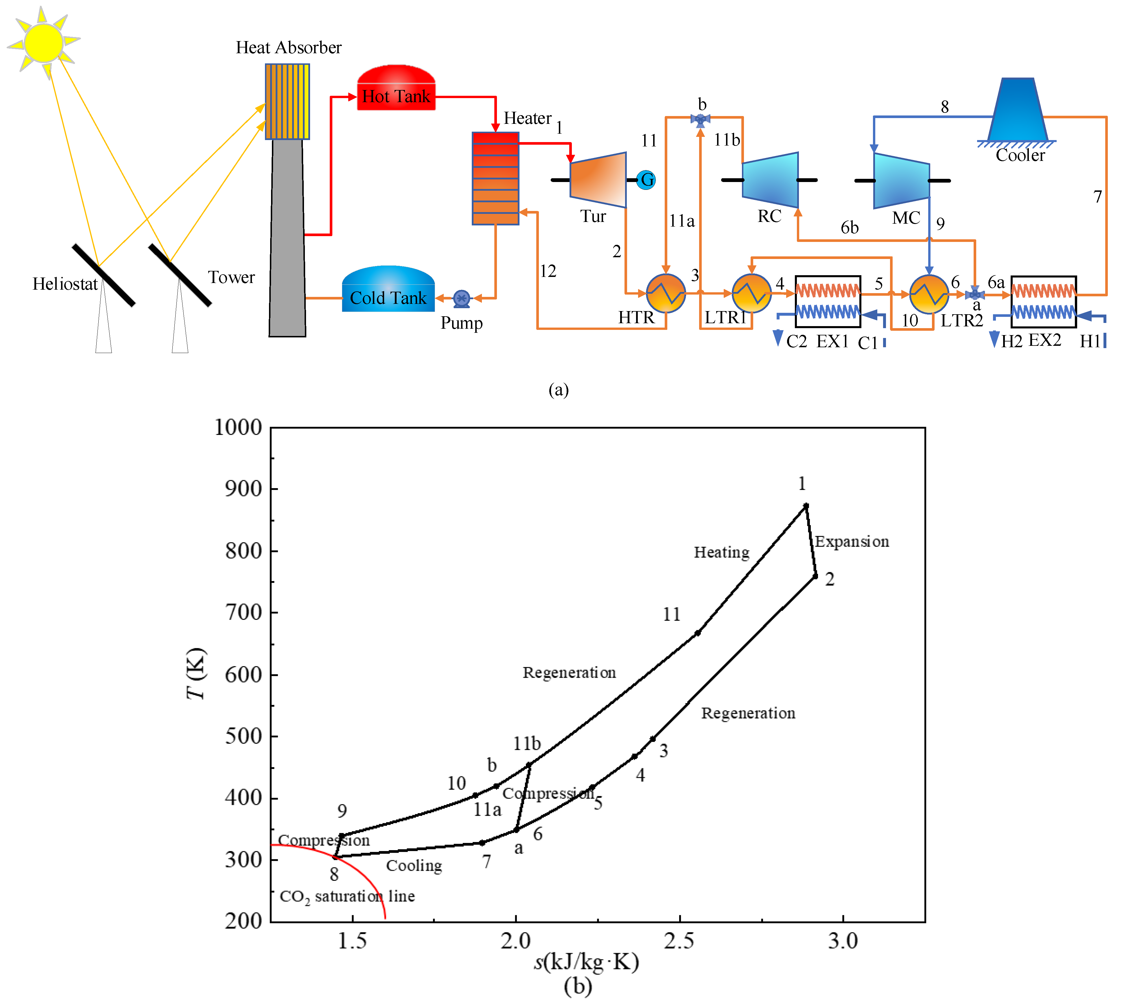
2.1. Supercritical CO2 CCHP System

The CCHP system (SCRBC/CCHP) is illustrated in Figure 1. The CCHP system is divided into two units: the solar energy collection unit and cogeneration of cold–heat–power. The cogeneration unit is composed of the electricity-generating, refrigeration, and heating sub-units. High-temperature thermal energy is used for generation, the medium-temperature waste heat is used for driving the absorption refrigeration, and the low-temperature waste heat is used for heating, meeting three kinds of energy supply.
The operating process of the solar collection unit is summarized as follows: when the irradiation is sufficient, the molten salt absorbs solar energy at the absorber. A part of the heat is reserved in the hot tank, the rest is utilized to drive the supercritical CO2 power cycle. The low-temperature molten salt flows through the cold tank into the receiver to absorb solar energy. When the irradiation is insufficient, the molten salt stored in the hot tank flows through the heater to drive the supercritical CO2 power cycle.
The running process of the cogeneration unit is as follows. The heater is used to heat the supercritical CO2, which then enters the turbine for expansion and performing work (1–2). Then, the working fluid flows through the high-temperature regenerator (2–3) and low-temperature regenerator 1 (3–4) to recover thermal energy. After heat exchange, the medium-temperature working fluid provides heat to the refrigeration unit and drives its operation. The working fluid flowing out from low-temperature regenerator 2 (5–6) is divided into two sections. One section flows into the heat exchanger EX2 (6a–7) to operate the heating equipment, and passes through main compressor after cooling. The other section of the working fluid flows directly into the recompressor (6b–11b).
The characteristics of the cogeneration system are summarized as follows:
(1)
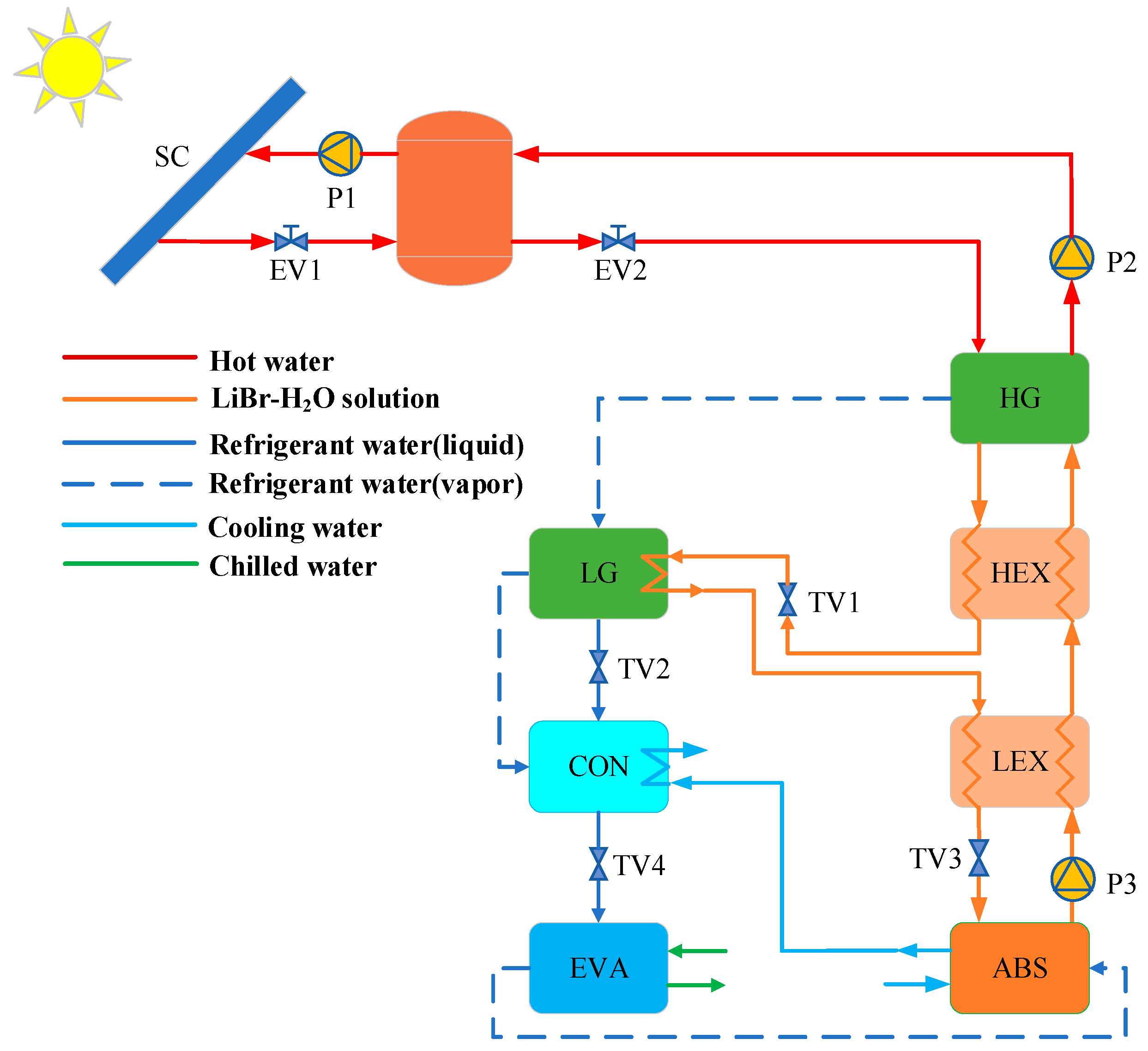
Compared with a single supercritical CO2 power cycle, the system realizes cogeneration of cooling, heating, and electricity. The higher temperature heat is used for the turbine, the medium-temperature waste heat drives the operation of the absorption refrigeration, and the low-temperature waste heat is utilized for heating, thus achieving the cascaded utilization of solar thermal energy.
(2)
The energy utilization factor of the cogeneration system is improved, the irreversible losses of the recuperation process are reduced, and the heat of the turbine outlet in the supercritical CO2 power cycle is used to drive refrigeration and heating.
(3)
The system uses solar energy to drive the system, achieving zero emission during operation. The system uses greenhouse gas CO2 as the working fluid, providing an effective way to utilize the greenhouse gases.

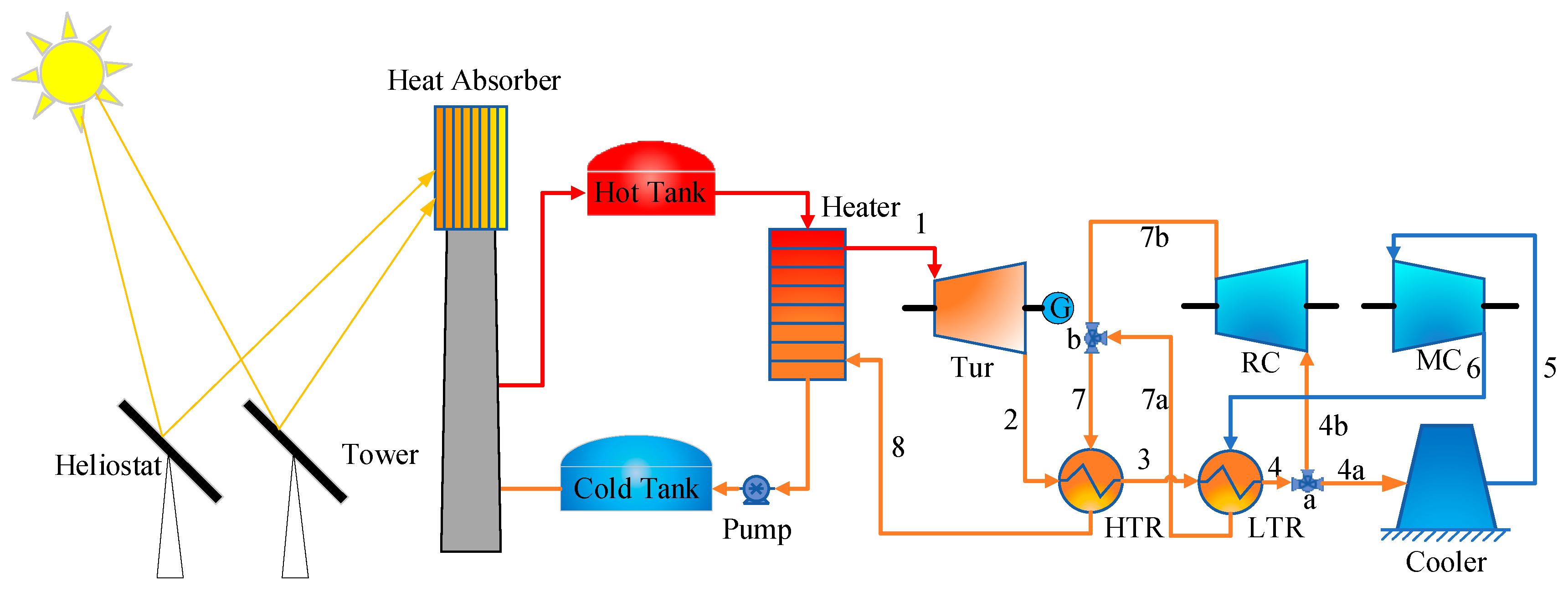
2.2. Reference System

The reference system consists of three parts: the supercritical CO2 recompression Brayton cycle, the solar direct-heating unit, and the dual-effect lithium bromide absorption refrigeration unit.
The schematic drawing of the SCRBC is illustrated in Figure 2. S-CO2 flows into the turbine to expand and do work (1–2) after heating. Then, the working fluid passes through the high-temperature regenerator (2–3) and the low-temperature regenerator to recover heat. After heat exchange, it is divided into two parts. One part of the working fluid is directed towards the main compressor (MC), while another part of the working fluid is channeled towards the recompressor (4b–7b).
The refrigeration unit adopts the dual-effect lithium bromide absorption refrigeration cycle, as illustrated in Figure 3, which mainly includes: a condenser (CON), high-pressure generator (HG), evaporator (EVA), high-temperature heat exchanger (HEX), absorber (ABS), low-pressure generator (LG), and a low-temperature heat exchanger (LEX).
The solar heating unit is composed of a heat source and heat exchanger, in which water is utilized as a heat transfer fluid, as illustrated in Figure 4. The thermal energy is provided by solar energy directly for heating.

2.3. System Assumptions

The physical parameters of the working fluid are from REFPROP. In order to investigate the system performance, the subsequent assumptions are considered:
(1)
The change of potential energy is not considered during the process of the system [35].
(2)
The heat losses between components and pipelines are ignored.
(3)
The thermal resistance of the metal wall in a Printed Circuit Heat Exchanger (PCHE) is ignored. The thermal resistance result of the metal partition is much less than that of the fluid boundary, and the temperature disparity between the two surfaces of the metal is comparatively insignificant. It is assumed that the thermal resistance of the shell of the pipe is ignored [36].

3. Model of the Supercritical CO2 CCHP System

3.1. Mathematic Model of Supercritical CO2 CCHP System

3.1.1. Heat Exchanger Model

The equation for energy conservation of the heat exchanger is as follows:
h h , i n h h , o u t = h c , o u t h c , i n
h h , i n h h , o u t = 1 S R h c , o u t h c , i n
where hh,in and hh,out are the enthalpy values at the hot end; hc,in and hc,out represent the enthalpy values at the cold end.
The calculation of heat transfer in the recuperator is determined as follows:
Q a v e = m h h h , i n h h , o u t + m c h c . o u t h c , i n 2
The total heat transfer coefficient is defined as:
U = Q a v e A Δ T m
where A is the total area of heat transfer.
The logarithmic mean temperature difference is defined as ∆Tm [37]:
Δ T m = T h , i n T c , o u t T h , o u t T c , i n ln T h , i n T c , o u t T h , o u t T c , i n
The CO2 is at the turbulent condition. According to the Gnielinsk equation [38], the Nusselt number is given as follow:
N u h = f h 8 Re 1000 Pr 1 + 12.7 f h 8 1 2 Pr 2 3 1
The Darcy friction factor is defined as:
f h = 1 1.8 log Re 1.5 2
Reynolds number:
Re = ρ ν d e μ
Hydraulic diameter:
d e = 4 π d c 2 8 π d c 2 + d c
Heat exchanger efficiency [39]:
ε = Q a v e Q i d e a l = Q a v e min Q c a s e , a , Q c a s e , b , Q c a s e , c
Q c a s e , a = m h h T h , i n , P h h T c , i n , P h
Q c a s e , b = m c h T h , i n , P c h T c , i n , P c
Q c a s e , c = m h h T h , i n , P h h T m , P h + m c h T m , P c h T c , i n , P c
where ρ is the density of CO2; μ is the viscosity coefficient of CO2; dc is the circumference diameter; and mh and mc are the mass flow of the hot side and cold side, respectively. Qideal represents the heat transfer under ideal conditions; Ph and Pc are the pressure of the hot end and cold end, respectively. Th,in and Tc,in are the inlet temperature of the hot end and cold end, respectively. Th,out and Tc,out are the outlet temperature of the hot end and cold end, respectively; Tm is the pinch-point temperature.
Table 1 illustrates the comparison results of experimental data [40] and the heat exchanger model. The small discrepancy indicates the precision of the model.

3.1.2. Turbine/Compressor Model

The equations for turbine efficiency-flow rate and expansion ratio-flow rate, shown in Formulas (14)–(16), are obtained by fitting the turbine performance curve [41].
η T u r = a 1 sin b 1 m c o r r e c t , T + c 1
m c o r r e c t , T = m T T T u r , i n P T u r , i n
where mcorrect,T is the correct mass flow rate of the turbine, with a range of 5 × 10⁻⁵ kg/s to 9 × 10⁻⁵ kg/s; a1 = 0.7865, b1 = 103, and c1 = 0.9373; TTur,in is the turbine inlet temperature; PTur,in is the turbine inlet pressure.
P T u r , i n P T u r , o u t = a 1 e m c o r r e c t b 1 c 1 2
where a1 = 0.8404, b1 = 3.675, and c1 = 21.79; PTur,in and PTur,out refer to the pressure at the inlet and outlet of the turbine, respectively.
The calculation of the turbine’s outlet temperature is performed as follows:
T T u r , o u t = 1 + 1 η T u r P T u r , i n P T u r , o u t k 1 k 1 T T u r , i n
where TTur,in and TTur,out are the turbine inlet temperature and outlet temperature, respectively; ηTur is the isentropic efficiency.
By fitting the compressor performance curve, the obtained fitting equations for compressor efficiency-flow and head coefficient-flow are calculated as follows:
η C o m = a 1 sin b 1 m c o r r e c t , C o m + c 1
m c o r r e c t , C o m = m C o m T C o m , i n P C o m , i n
where mcorrect,Com represents the correct mass flow of the RC (recompressor) and MC (main compressor), with a range of 1 × 10⁻⁵ kg/s to 10 × 10−5 kg/s; a1 = 0.7714, b1 = 28.34, c1 = 0.6427.
The Equation (20) used to determine the discharge temperature of the compressor is as follows:
T C o m , o u t = 1 + 1 η C o m P C o m , o u t P C o m , i n k 1 k 1 T C o m , i n
where TCom,in and TCom,out represent the temperature of CO2 entering and exiting the compressor, respectively; k is the adiabatic index in adiabatic compression; PCom,in and PCom,out represent the pressure at which CO2 enters and exits the compressor, respectively.
Table 2 illustrates the discrepancies among the experimental data and model data. A smaller discrepancy indicates the accuracy of the calculated model of turbine and compressor.

3.2. Thermodynamic Analyses of Cogeneration System

The cogeneration system’s exergy balance is formulated by applying the principles of the Second Law of Thermodynamics.
For the process of energy exchange, the exergy balance equations [42] are as follows:
d E c v d t = j E i n p u t + E W , i n E W , o u t + E i n E o u t E D
E i n p u t = 1 T 0 T R Q H e a t e r
E i n E o u t = m e i n e o u t
e = h h 0 T 0 s s 0 + ν 2 2 + g z
T R = T i n , T u r + Δ T R
where d E c v d t is the derivative, which is equal to zero under steady conditions. Einput represents the exergy generating from the transfer of heat source, that is, the total input exergy of the system; Ein and Eout are the exergy of inflow and outflow, respectively; EW,in and EW,out are input work and output work, respectively; ED denotes the exergy destruction; QHeater is the heat transferred, which is the total heat absorbed by the system; T0 refers to the environmental reference temperature, taken as 25 °C; TR represents the temperature of the heat source; Tin,Tur refers to the temperature at which the turbine’s inlet is operating; and ∆TR is the difference of the receiver temperature, taken as 150 °C [5].
The exergy destruction of each component is obtained through exergy balance equations:
Turbine:
E d , T u r = m C O 2 e 1 e 2 W T
Main compressor:
E d , M C = S R m C O 2 e 7 e 6 + W M C
Recompressor:
E d , R C = 1 S R m C O 2 e 10 e 9 + W R C
High-temperature regenerator:
E d , H T R = m C O 2 e 2 e 3 e 12 e 11
Low-temperature regenerator:
E d , L T R = m C O 2 e 3 e 4 S R m C O 2 e 8 e 7
Cooler:
E d , C o o l e r = S R m C O 2 e 4 e 5
Heater:
E d , H e a t e r = E i n p u t m C O 2 e 1 e 11
where m C O 2 represents the mass flow rate; e1, e3, e4, e7, e10, e12 are the inlet exergy of the components; e2, e5, e6, e8, e9, e11 are the outlet exergy of the components.
According to the principles of thermodynamics, the system’s performance is assessed by considering both its EUF and exergy efficiency.
The EUF:
E U F = W n e t + Q 1 + Q 2 Q H e a t e r = W T u r W M C W R C + Q 1 + Q 2 Q H e a t e r
where Q1 and Q2 are the cooling and heating output in kW, respectively; for the reference system, it is essential to guarantee the same generation, cooling, and heating capacity as the cogeneration system.
Exergy efficiency:
η e x = W n e t + E 1 + E 2 E i n p u t = 1 i E d , i E i n p u t
where E1 is the exergy output of energy release side in EX1, kW; E2 is the exergy output of energy release side in EX2, kW; Ed,i is the exergy destruction of system components, kW; Einput is the total exergy input, kW.

4. Results and Discussion

To investigate the thermal performance, thermal analyses were carried out at the design conditions. Subsequently, an evaluation was conducted on the system’s output capabilities while considering varying cooling and heating capacities. Finally, with the variation of solar irradiance in the whole year, the thermodynamic analyses of the system were carried out.

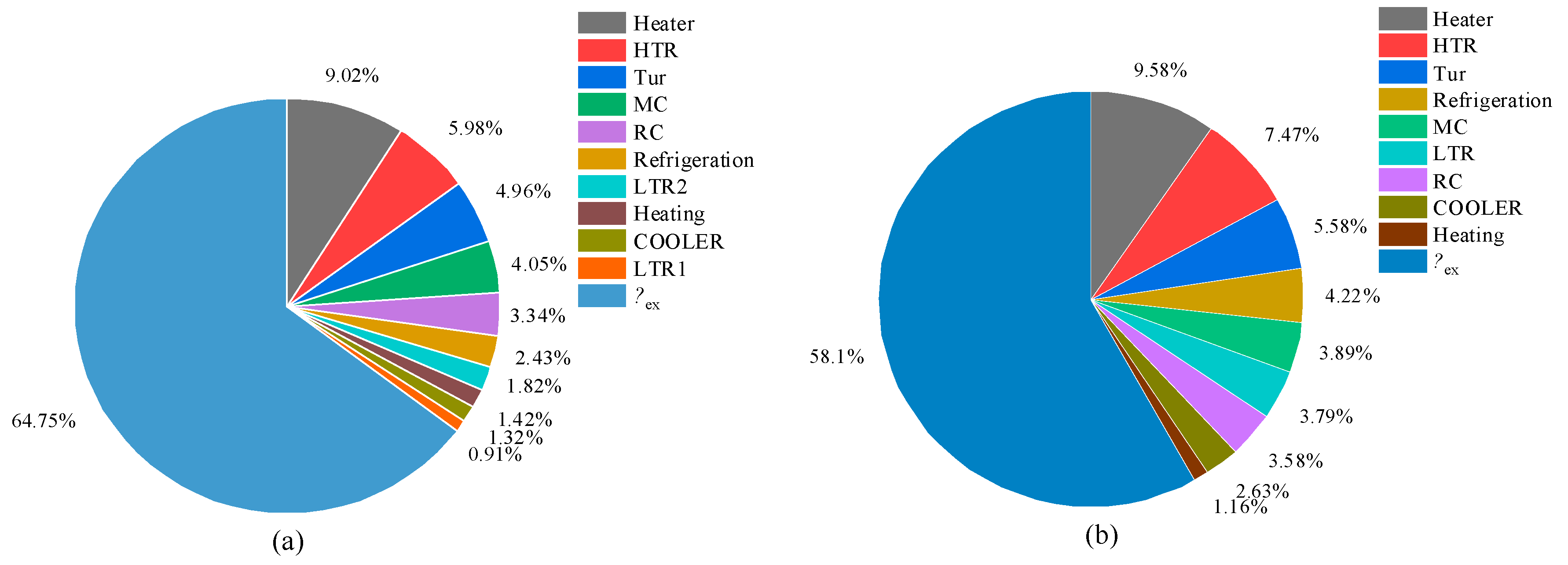
4.1. Thermal Performance at the Design Condition

The design parameters are illustrated in Table 3. The location of this cogeneration system is Qingdao, China. The meteorological parameters were obtained by TRNSYS.
Table 4 shows the design conditions utilized to conduct thermodynamic evaluations for both the SCRBC/CCHP and reference systems. The same capacities of electricity, cooling, and heating were set in the SCRBC/CCHP and reference systems. The electricity, refrigeration, and heating capacities are 6.4 MW, 1.27 MW, and 0.85 MW, respectively, accounting for 63.7%, 12.6%, and 8.4% of the total input energy. The proposed system achieves an EUF of 84.7% and exergy efficiency of 64.8%, which are 9.7% and 10.3% higher, respectively, than the reference system. The irreversible losses are reduced and the efficiency is improved by the cascade utilization of waste heat in the turbine outlet.
To investigate the irrecoverable losses of the components in our CCHP system, we performed the exergy analyses conducted in Figure 5. The cogeneration system achieves an exergy efficiency of 64.8%, with the heater identified as the component responsible for the highest amount of irreversible loss. The high-temperature regenerator incurs significant exergy loss as it operates with a relatively high temperature at the turbine outlet, resulting in a substantial temperature disparity between its cold and hot ends. The reduction in irreversible loss in the regenerative process contributes to an enhancement in the exergy efficiency of cogeneration systems.

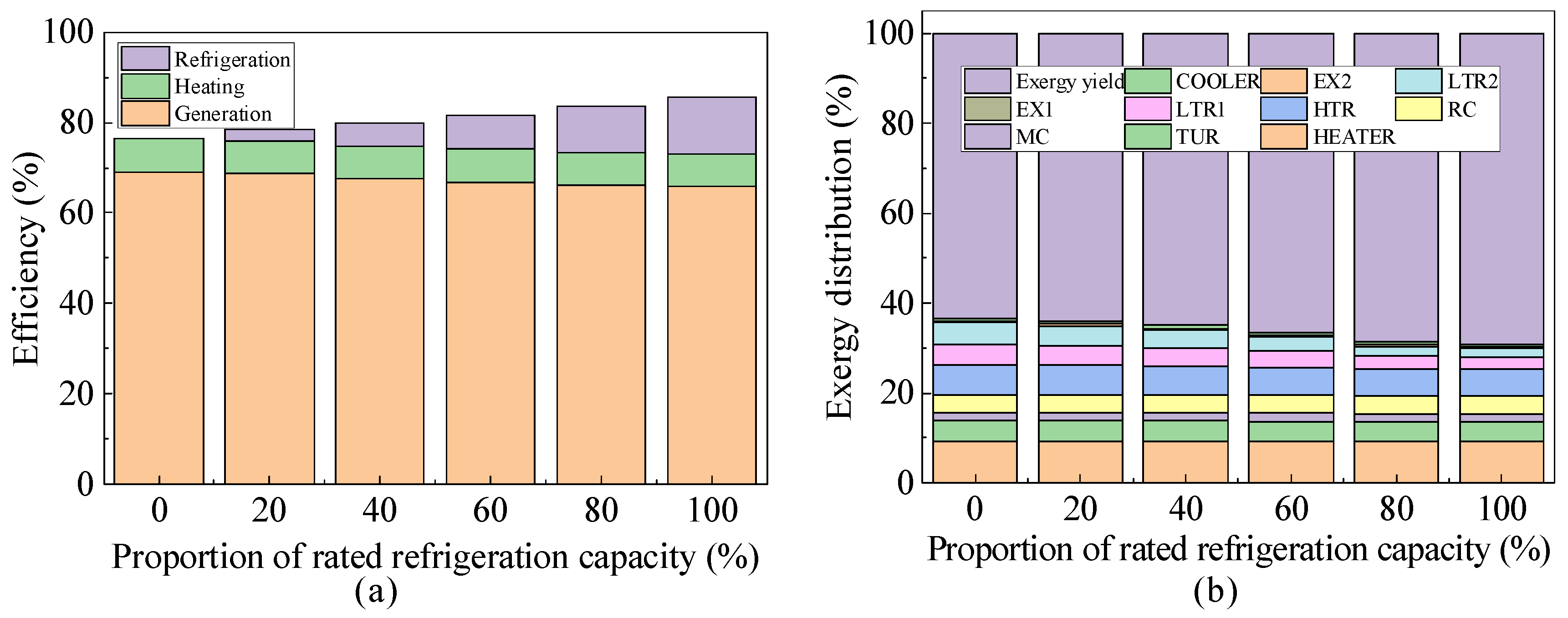
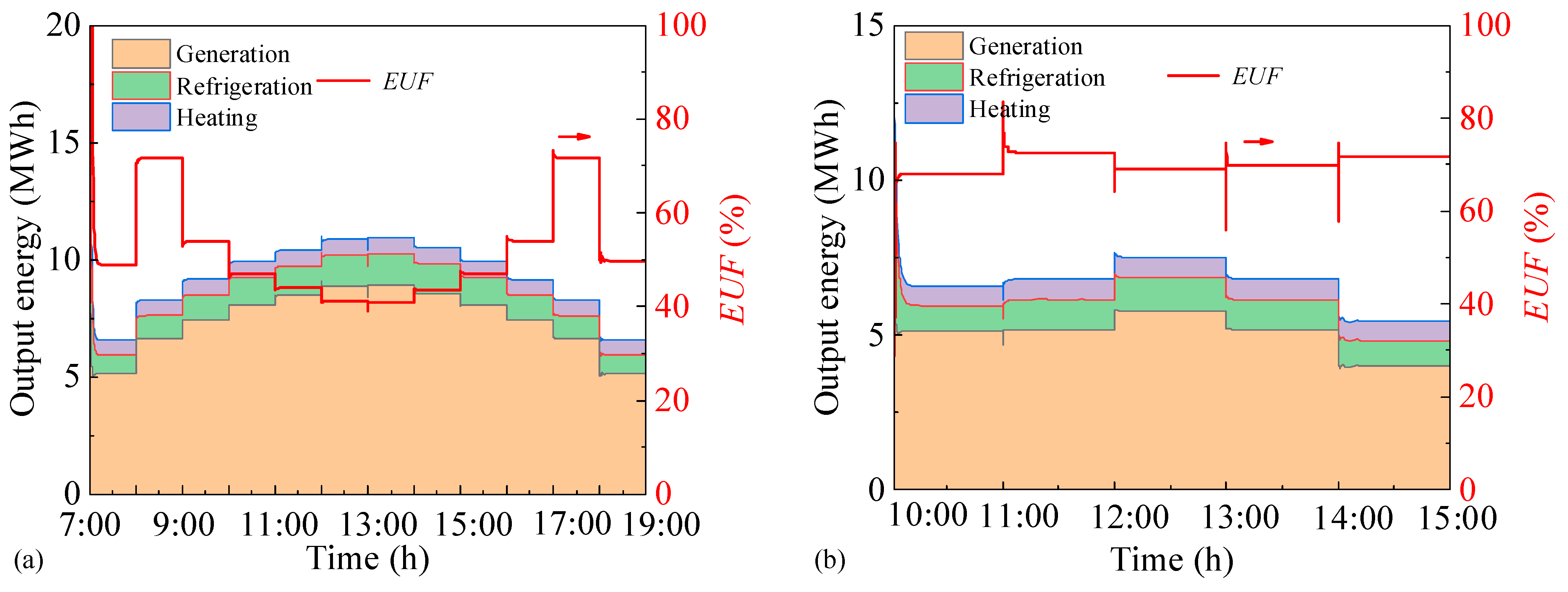
4.2. Thermodynamic Analyses of Cogeneration System with the Variation of Loads

In order to investigate the performance of the system with the variations of cooling and heating capacity, thermodynamical analyses of the system were carried out.
System performance was analyzed with the variation of the refrigeration load. More input heat is used for cooling with the increase in cooling load, and the net work and heating load are gradually reduced. The EUF and irreversible loss in the cogeneration system were obtained through thermodynamic analysis. As shown in Figure 6a, the EUF of the system is in the range of 76.6~84.7%. The system exhibits an increase in exergy efficiency from 61.3% to 64.8%, as depicted in Figure 6b. The increase in cooling load leads to a higher utilization of waste heat, while simultaneously reducing the irreversible loss during the process of waste heat utilization.
Furthermore, system performance was analyzed with the changing the heating load. EUF values and the exergy distribution of the cogeneration system were obtained through thermodynamic analysis. As shown in Figure 7a, the EUF of the system ranges from 80.5% to 84.7%, and the exergy efficiency of the system increases from 60.8% to 64.8%, as illustrated in Figure 7b. The explanation lies in the fact that as the heating load increases, there is a corresponding rise in the utilization of residual heat at the turbine outlet. This leads to a decrease in irreversible losses during the regeneration process.

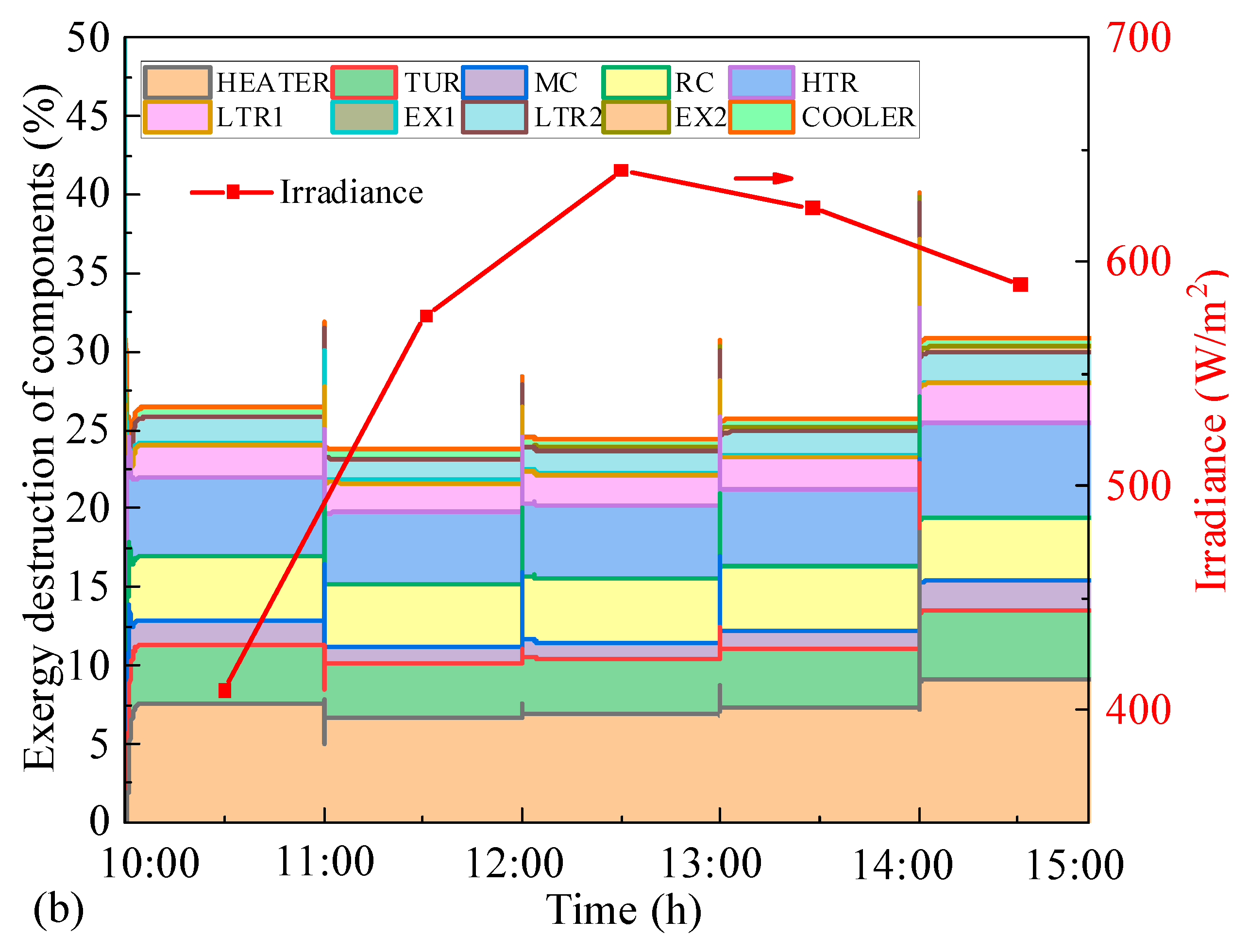
4.3. Thermodynamic Analyses of Cogeneration System with the Variation of Radiation

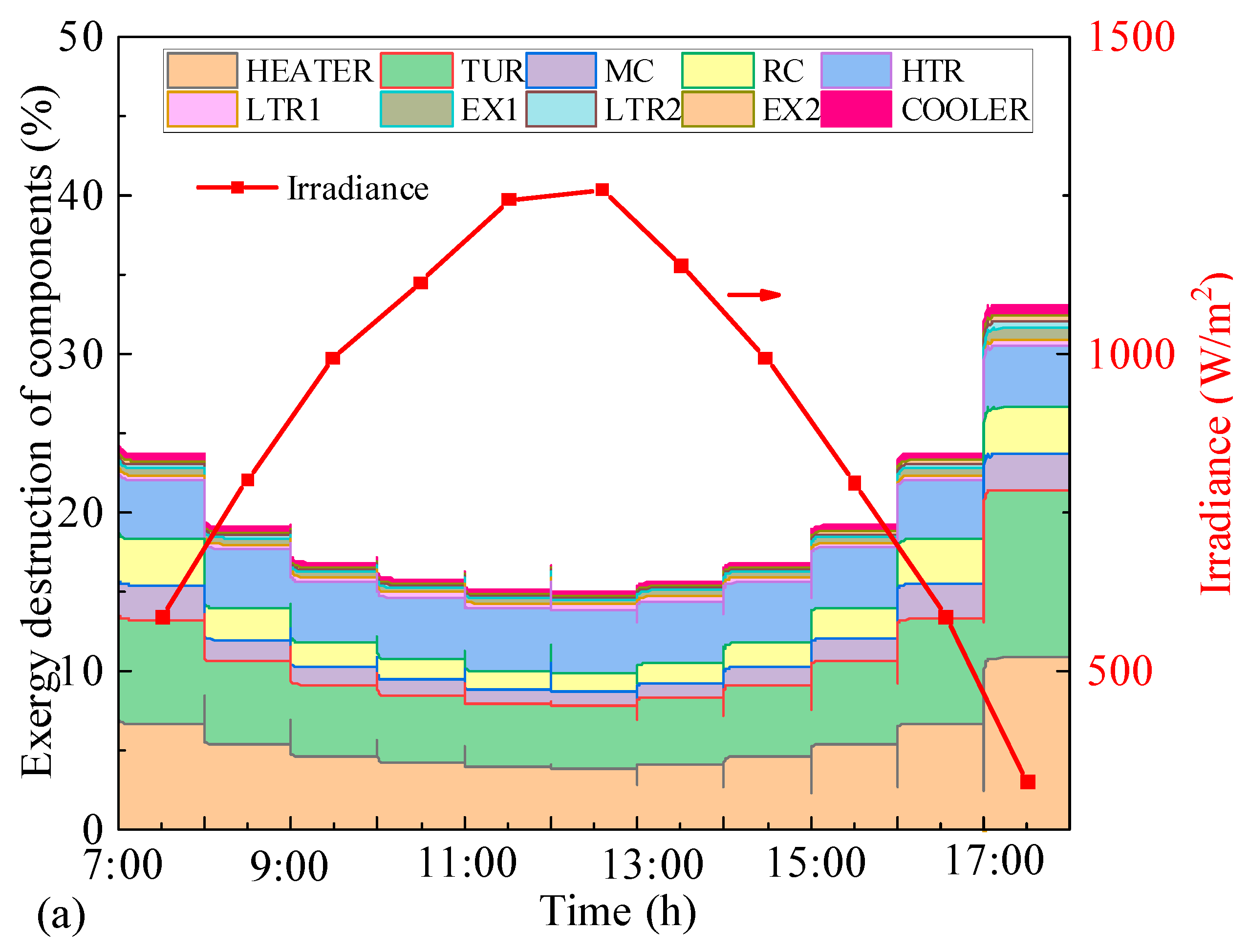
4.3.1. Thermodynamic Analyses in Typical Days

In an effort to investigate the influence of irradiance on the CCHP system, the performance of the CCHP system on typical days was analyzed.
As shown in Figure 8, the changes in the EUF and the output energy of cold, heat, and electricity over time on typical days (8 June, 18 January) were obtained.
The EUF and output energy on typical days varied with time. The EUF of the system is in the range of 40.8~73.1% on a summer day, and in the range of 41.6~72.6% on a typical winter day. The highest EUF exists when the solar irradiation is close to the design point. With the increase in solar irradiance, the CCHP system demonstrates an enhancement in the total input energy, resulting in increased output energy and net work; however, the overall input of the system is increasing at a higher rate compared to the increase in output of the CCHP system. As a result, there is a continuous decrease in the ratio between these two factors, known as the EUF of the system.
As depicted in Figure 9, the system components’ exergy distribution is illustrated in typical days. The component with the largest irreversible loss is the heater, because the difference in energy grade during the collection process is large. The high-temperature regenerator is the second most significant factor contributing to irreversibility, primarily due to the relatively high temperature at the turbine outlet and a substantial temperature gradient between its cold and hot ends. Comparing the performances of different seasons, the highest exergy efficiency and solar irradiation is on a summer day, and the exergy efficiency is in the range of 66.8~84.4%. In the wake of the increase in solar irradiation, the irreversible loss decreases in the CCHP system. The reason for this is that with increasing solar irradiation, the temperature of the working fluid is also increased. The temperature difference at the two sides of heater is decreased, and the irreversible loss of the heater is decreased.

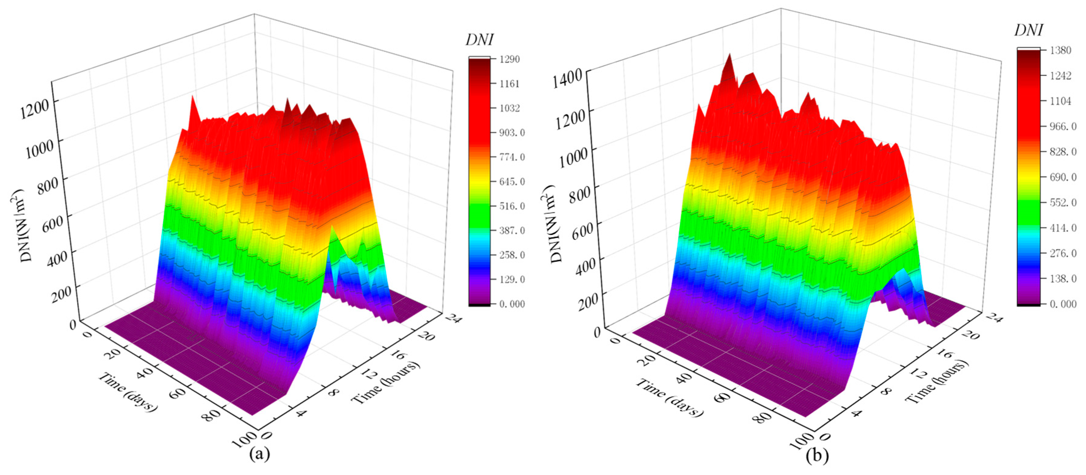
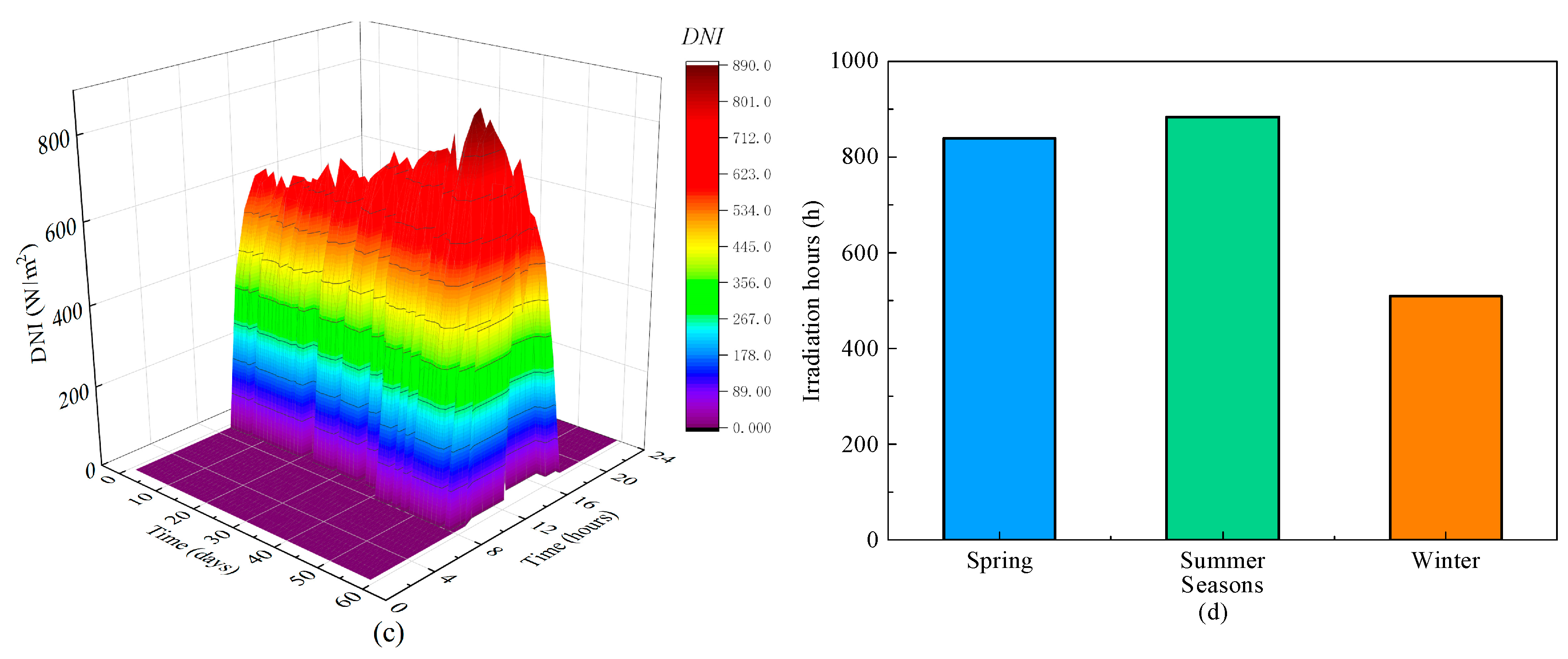
4.3.2. Thermodynamic Analyses of the System in Different Seasons

In an effort to explore the influence of irradiance on system, the different solar irradiances in spring, summer, and winter were selected. With consideration of variation of energy demand, the system in spring and summer was set with the output of cold–heat–electricity, and the system in winter was set with the output of heat and electricity. The solar irradiances in spring, summer, and winter seasons are shown in Figure 10a–c. Figure 10d shows the comparison of irradiation duration in three seasons. The variation of solar irradiation in spring is in the range of 301.3 W/m2~1291.7 W/m2. The variation of solar irradiation in summer is in the range of 300.0 W/m2~1377.6 W/m2. The variation of solar irradiation in winter is in the range of 300.4 W/m2~890.2 W/m2. The longest irradiation time exists in summer, with irradiation hours of 883 h.
By simulating the solar irradiance in spring (March, April, and May), EUF varies from 62.0% to 84.5%. In summer (June, July, and August), the system EUF varies from 61.0% to 84.6%. By simulating the solar irradiance in winter (December, January, and February), the change range of the system EUF is 47.0~80.7%. The thermodynamic performances of the system are observed in Figure 11 in different seasons. The EUF varies from 62.0% to 84.5% in spring, and the ranges of EUF are 61.0% to 84.6% in summer, and 47.0~80.7% in winter. Through the comparison, the EUF in winter is relatively lower than that in spring and summer, mainly because the solar irradiance in winter is lower, and the operation of the system with the output of heat and electricity is in off-design condition. The average EUF in spring, summer, and winter are 71.1%, 73.3%, and 47.2%, respectively. The EUF in spring and summer are 33.5% and 35.6% higher, respectively, than that in winter.

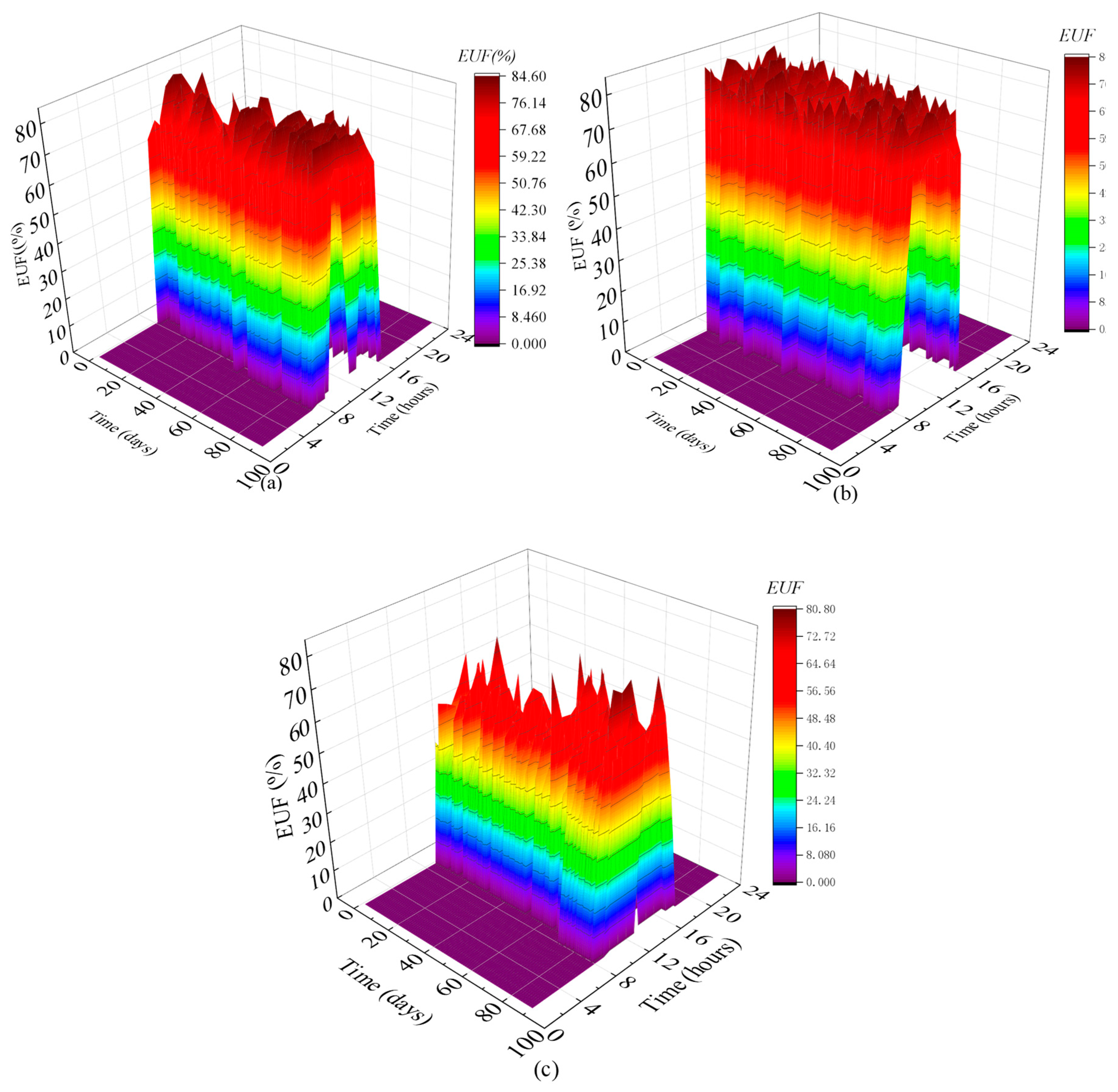
4.3.3. Thermodynamic Analysis of Cogeneration System throughout the Year

The influence of irradiance variation on system performance within a year was analyzed. The variation of solar irradiance in Qingdao in a whole year is observed in Figure 12a. According to solar irradiance, the heat absorption in the solar receiver was obtained and is shown in Figure 12b.
In order to analyze the thermodynamic performance, the changes in power production, cooling, heating, and EUF throughout the entire year were obtained, as illustrated in Figure 13. It can be observed that the system has the highest energy output in summer, due to the longest daily irradiation time and the highest solar irradiation amount. The EUF of the system varies from 45.9% to 74.9% in the period of twelve months. The average annual EUF of the proposed system is 65.4%.

5. Conclusions

The cogeneration system based on a solar-driven supercritical CO2 recompression Brayton cycle is proposed to make full use of the waste heat in the supercritical CO2 Brayton cycle, realize the trigeneration of cooling–electricity–heating, and improve the CCHP performance. The high-temperature heat is used for power generation, the medium-temperature waste heat drives the operation of the absorption refrigeration sub-unit, and the low-temperature waste heat is used for heating, realizing the cascade utilization of solar thermal energy. The cogeneration system was subjected to thermodynamic analyses, considering the design condition, varying load, and changing irradiation conditions. The findings can be summarized as follows:
(1)
A constructed model was utilized to analyze the thermodynamics of a cogeneration system under the function of a supercritical CO2 power cycle. At designed working condition, the EUF of the cogeneration system and exergy efficiency are 84.7% and 64.8%, which increased by 11.5% and 10.3% compared with the reference system.
(2)
The system performance was determined through thermodynamic analysis, taking into account the variations in the user’s requirements for cooling and heating. Under variable refrigeration load and heating load, the ranges of EUF are 76.3~84.7% and 80.5~84.7%, and the exergy efficiency is in the range of 63.4~64.8% and 63.9~64.8%.
(3)
Considering the variation of solar irradiation, the thermal performances of the cogeneration system on representative days and in the whole year were investigated. Under solar irradiation on typical days, the system EUF and exergy efficiency were obtained. The system EUF in spring, summer, and winter are in the range of 62.0~84.5%, 61.0~84.6%, and 47.0~80.7%. The annual EUF of the proposed system is 65.4%.
In summary, the proposed supercritical CO2 cogeneration system offers an effective approach for the application of solar energy. The outlook is summarized as follows: Investigation of the system in different climatic areas are worth conducting to illustrate the adaptability of the system. Furthermore, considering the variation of solar irradiation, the capacity of energy storage will be taken into account in future work.

Author Contributions

Software, R.Z., S.Y. and X.S.; Data curation, R.Z.; Writing—original draft, R.Z.; Writing—review & editing, R.Z. and X.W. All authors have read and agreed to the published version of the manuscript.

Funding

This work was supported by the Natural Science Foundation of Shandong Province, China (Grant NO. ZR2021QE298).

Data Availability Statement

The original contributions presented in the study are included in the article, further inquiries can be directed to the corresponding author.

Conflicts of Interest

Authors confirm that there are no known conflicts of interest associated with this manuscript.

Nomenclature

Latin symbols
Aarea (m2)
A’energy grade
dehydraulic diameter (m)
E/eexergy (kW, MW)
EUFenergy utilization factor
fDarcy friction factor
hspecific enthalpy (kJ kg−1)
kthe adiabatic index in adiabatic compression
mmass flow rate (kg s−1)
Nrotary speed (rpm)
NuNusser number
Ppressure (kPa, MPa)
PrPrandtl number
Qheating capacity (kW, MW)
Q1the cooling output of system
Q2the heating output of system
ReReynolds number
sspecified entropy (kJ kg−1 K−1)
SRsplit ratio
Ttemperature (°C or K)
Tmtemperature difference (°C)
Uthe total heat transfer coefficient
Wcompressor power consumption (kW)
Greek symbols
ρdensity
μcoefficient of kinetic viscosity
εheat exchanger efficiency
ηefficiency
Abbreviations
Comcompressor
EX1heat exchanger1
EX2heat exchanger2
HTRhigh-temperature regenerator
LTRlow-temperature regenerator
MCmain compressor
RCrecompressor
S-CO2supercritical CO2
Turturbine
Subscripts and superscripts
0ambient
1, 2, 3, 4, 5, 6, 7, 8, 9…state point
Aair
ccold
comcompressor
ddestruction
eaenergy accept
edenergy discharge
hhot
ininlet
outoutlet
tottotal

References

  1. Linares, J.I.; Montes, M.J.; Cantizano, A.; Sánchez, C. A novel supercritical CO2 recompression Brayton power cycle for power tower concentrating solar plants. Appl. Energy 2020, 263. [Google Scholar] [CrossRef]
  2. Kumar, V.; Duan, L. Off-Design Dynamic Performance Analysis of a Solar Aided Coal-Fired Power Plant. Energies 2021, 14, 2950. [Google Scholar] [CrossRef]
  3. De Oliveira, A.P.; Lorenzini, G.; Shah, Z.; Klunk, M.A.; de Carvalho Lima, J.E.; Rocha, L.A.O.; Caetano, N.R. Hierarchical Criticality Analysis of Clean Technologies Applied to a Coal-Fired Power Plant. Int. J. Des. Nat. Ecodynamics 2020, 15, 609–619. [Google Scholar] [CrossRef]
  4. Padilla, R.V.; Too, Y.C.S.; Benito, R.; McNaughton, R.; Stein, W. Thermodynamic feasibility of alternative supercritical CO2 Brayton cycles integrated with an ejector. Appl. Energy 2016, 169, 49–62. [Google Scholar] [CrossRef]
  5. Padilla, R.V.; Soo Too, Y.C.; Benito, R.; Stein, W. Exergetic analysis of supercritical CO2 Brayton cycles integrated with solar central receivers. Appl. Energy 2015, 148, 348–365. [Google Scholar] [CrossRef]
  6. Wang, K.; He, Y.-L.; Zhu, H.-H. Integration between supercritical CO2 Brayton cycles and molten salt solar power towers: A review and a comprehensive comparison of different cycle layouts. Appl. Energy 2017, 195, 819–836. [Google Scholar] [CrossRef]
  7. Padilla, R.V.; Benito, R.G.; Stein, W. An Exergy Analysis of Recompression Supercritical CO2 Cycles with and without Reheating. Energy Procedia 2015, 69, 1181–1191. [Google Scholar] [CrossRef]
  8. Dostal, V.; Hejzlar, P.; Driscoll, M.J. The Supercritical Carbon Dioxide Power Cycle: Comparison to Other Advanced Power Cycles. Nucl. Technol. 2017, 154, 283–301. [Google Scholar] [CrossRef]
  9. Liang, Y.; Chen, J.; Luo, X.; Chen, J.; Yang, Z.; Chen, Y. Simultaneous optimization of combined supercritical CO2 Brayton cycle and organic Rankine cycle integrated with concentrated solar power system. J. Clean. Prod. 2020, 266, 121927. [Google Scholar] [CrossRef]
  10. Turchi, C.; Ma, Z.; Neises, T. Thermodynamic Study of Advanced Supercritical Carbon Dioxide Power Cycles for High Performance Concentrating Solar Power Systems. In Proceedings of the ASME 2012 6th International Conference on Energy Sustainability collocated with the ASME 2012 10th International Conference on Fuel Cell Science, Engineering and Technology, San Diego, CA, USA, 23–26 July 2012. [Google Scholar]
  11. Mahmood, A.; Bano, S.; Yu, J.H.; Lee, K.-H. Effect of operating conditions on the performance of solid electrolyte membrane reactor for steam and CO2 electrolysis. J. Membr. Sci. 2015, 473, 8–15. [Google Scholar] [CrossRef]
  12. Ortega, J.; Khivsara, S.; Christian, J.; Ho, C.; Yellowhair, J.; Dutta, P. Coupled modeling of a directly heated tubular solar receiver for supercritical carbon dioxide Brayton cycle: Optical and thermal-fluid evaluation. Appl. Therm. Eng. 2016, 109, 970–978. [Google Scholar] [CrossRef]
  13. Zhang, X.R.; Yamaguchi, H.; Fujima, K.; Enomoto, M.; Sawada, N. Theoretical analysis of a thermodynamic cycle for power and heat production using supercritical carbon dioxide. Energy 2007, 32, 591–599. [Google Scholar] [CrossRef]
  14. Neises, T.; Turchi, C. A Comparison of Supercritical Carbon Dioxide Power Cycle Configurations with an Emphasis on CSP Applications. Energy Procedia 2014, 49, 1187–1196. [Google Scholar] [CrossRef]
  15. Pasch, J.J.; Thomas, M.C.; Darryn, D. Supercritical CO2 Recompression Brayton Cycle; National Nuclear Security Administration: Springfield, VA, USA, 2012. [Google Scholar]
  16. Conboy, T.; Pasch, J.; Fleming, D. Control of a Supercritical CO2 Recompression Brayton Cycle Demonstration Loop. J. Eng. Gas Turbines Power 2013, 135, 111701. [Google Scholar] [CrossRef]
  17. Ibrahim, A.G.M.; Rashad, A.M.; Dincer, I. Exergoeconomic analysis for cost optimization of a solar distillation system. Sol. Energy 2017, 151, 22–32. [Google Scholar] [CrossRef]
  18. Wang, X.; Wang, J.; Zhao, P.; Dai, Y. Thermodynamic Comparison and Optimization of Supercritical CO2 Brayton Cycles with a Bottoming Transcritical CO2 Cycle. J. Energy Eng. 2016, 142, 04015028. [Google Scholar] [CrossRef]
  19. Caetano, N.R.; Barreto, E.X.; Ruoso, A.C.; Klunk, M.A.; Wander, P.R. Exergetic analysis in a combined gas-steam power cycle with two regenerators in parallel. Int. J. Hydromechatron. 2020, 3, 109–127. [Google Scholar] [CrossRef]
  20. Akbari, A.D.; Mahmoudi, S.M.S. Thermoeconomic analysis & optimization of the combined supercritical CO2 (carbon dioxide) recompression Brayton/organic Rankine cycle. Energy 2014, 78, 501–512. [Google Scholar] [CrossRef]
  21. Song, J.; Li, X.; Wang, K.; Markides, C.N. Parametric optimisation of a combined supercritical CO2 (S-CO2) cycle and organic Rankine cycle (ORC) system for internal combustion engine (ICE) waste-heat recovery. Energy Convers. Manag. 2020, 218, 112999. [Google Scholar] [CrossRef]
  22. Wang, S.; Zhang, L.; Liu, C.; Liu, Z.; Lan, S.; Li, Q.; Wang, X. Techno-economic-environmental evaluation of a combined cooling heating and power system for gas turbine waste heat recovery. Energy 2021, 231, 120956. [Google Scholar] [CrossRef]
  23. Pan, M.; Zhu, Y.; Bian, X.; Liang, Y.; Lu, F.; Ban, Z. Theoretical analysis and comparison on supercritical CO2 based combined cycles for waste heat recovery of engine. Energy Convers. Manag. 2020, 219, 113049. [Google Scholar] [CrossRef]
  24. Yang, Y.; Huang, Y.; Jiang, P.; Zhu, Y. Multi-objective optimization of combined cooling, heating, and power systems with supercritical CO2 recompression Brayton cycle. Appl. Energy 2020, 271, 115189. [Google Scholar] [CrossRef]
  25. Yari, M.; Sirousazar, M. A Novel recompression S-CO2 Brayton cycle with pre-cooler exergy utilization. Proc. Inst. Mech. Eng. Part A J. Power Energy 2010, 224, 931–946. [Google Scholar] [CrossRef]
  26. Mecheri, M.; Le Moullec, Y. Supercritical CO2 Brayton cycles for coal-fired power plants. Energy 2016, 103, 758–771. [Google Scholar] [CrossRef]
  27. Romero Rodríguez, L.; Salmerón Lissén, J.M.; Sánchez Ramos, J.; Rodríguez Jara, E.Á.; Álvarez Domínguez, S. Analysis of the economic feasibility and reduction of a building’s energy consumption and emissions when integrating hybrid solar thermal/PV/micro-CHP systems. Appl. Energy 2016, 165, 828–838. [Google Scholar] [CrossRef]
  28. Li, M.; Mu, H.; Li, N.; Ma, B. Optimal design and operation strategy for integrated evaluation of CCHP (combined cooling heating and power) system. Energy 2016, 99, 202–220. [Google Scholar] [CrossRef]
  29. Aghaziarati, Z.; Aghdam, A.H. Thermoeconomic analysis of a novel combined cooling, heating and power system based on solar organic Rankine cycle and cascade refrigeration cycle. Renew. Energy 2021, 164, 1267–1283. [Google Scholar] [CrossRef]
  30. Hou, H.; Wu, J.; Ding, Z.; Yang, B.; Hu, E. Performance analysis of a solar-assisted combined cooling, heating and power system with an improved operation strategy. Energy 2021, 227, 120516. [Google Scholar] [CrossRef]
  31. Lozano, M.A.; Ramos, J.C.; Carvalho, M.; Serra, L.M. Structure optimization of energy supply systems in tertiary sector buildings. Energy Build. 2009, 41, 1063–1075. [Google Scholar] [CrossRef]
  32. Mohammadi, A.; Kasaeian, A.; Pourfayaz, F.; Ahmadi, M.H. Thermodynamic analysis of a combined gas turbine, ORC cycle and absorption refrigeration for a CCHP system. Appl. Therm. Eng. 2017, 111, 397–406. [Google Scholar] [CrossRef]
  33. Eisavi, B.; Khalilarya, S.; Chitsaz, A.; Rosen, M.A. Thermodynamic analysis of a novel combined cooling, heating and power system driven by solar energy. Appl. Therm. Eng. 2018, 129, 1219–1229. [Google Scholar] [CrossRef]
  34. Al-Sulaiman, F.A.; Hamdullahpur, F.; Dincer, I. Performance assessment of a novel system using parabolic trough solar collectors for combined cooling, heating, and power production. Renew. Energy 2012, 48, 161–172. [Google Scholar] [CrossRef]
  35. Kizilkan, O.; Khanmohammadi, S.; Saadat-Targhi, M. Solar based CO2 power cycle employing thermoelectric generator and absorption refrigeration: Thermodynamic assessment and multi-objective optimization. Energy Convers. Manag. 2019, 200, 112072. [Google Scholar] [CrossRef]
  36. Wu, C.; Wang, S.-S.; Feng, X.-J.; Li, J. Energy, exergy and exergoeconomic analyses of a combined supercritical CO2 recompression Brayton/absorption refrigeration cycle. Energy Convers. Manag. 2017, 148, 360–377. [Google Scholar] [CrossRef]
  37. Wang, X.; Xu, W.; Xu, B.; Xiong, C.; Guo, S.; Chen, Z. Theoretical and numerical analysis of conjugate heat transfer for supercritical CO2 flowing in printed circuit heat exchanger. J. Supercrit. Fluids 2022, 189, 105717. [Google Scholar] [CrossRef]
  38. Alrobaian, A.A. Energy, exergy, economy, and environmental (4E) analysis of a multi-generation system composed of solar-assisted Brayton cycle, Kalina cycle, and absorption chiller. Appl. Therm. Eng. 2022, 204, 117988. [Google Scholar] [CrossRef]
  39. Son, S.; Heo, J.Y.; Lee, J.I. Prediction of inner pinch for supercritical CO2 heat exchanger using Artificial Neural Network and evaluation of its impact on cycle design. Energy Convers. Manag. 2018, 163, 66–73. [Google Scholar] [CrossRef]
  40. Ahmadi, M.H.; Ghazvini, M.; Sadeghzadeh, M.; Alhuyi Nazari, M.; Kumar, R.; Naeimi, A.; Ming, T. Solar power technology for electricity generation: A critical review. Energy Sci. Eng. 2018, 6, 340–361. [Google Scholar] [CrossRef]
  41. Han, R.Y. Research on Dynamic Characteristics of S-CO2 Recompression Brayton Cycle System. Master’s Thesis, Dalian University of Technology, Dalian, China, 2021. [Google Scholar]
  42. Siddiqui, M.E.; Almitani, K.H. Energy and Exergy Assessment of S-CO2 Brayton Cycle Coupled with a Solar Tower System. Processes 2020, 8, 1264. [Google Scholar] [CrossRef]
Figure 1. Supercritical CO2 CCHP system: (a) system schematic diagram; (b) system T-s diagram.
Energies 17 01767 g001
Figure 2. Schematic diagram of S-CO2 recompression Brayton cycle.
Energies 17 01767 g002
Figure 3. Dual-effect lithium bromide absorption refrigeration process.
Energies 17 01767 g003
Figure 4. Solar energy for heating.
Energies 17 01767 g004
Figure 5. Exergy destruction ratio of components: (a) cogeneration system, (b) reference system.
Energies 17 01767 g005
Figure 6. Thermodynamic analysis of cogeneration system with the variation of refrigeration capacity: (a) energy analysis, (b) exergy analysis.
Energies 17 01767 g006
Figure 7. Thermodynamic analysis of cogeneration system with the variation of heating capacity: (a) energy analysis, (b) exergy analysis.
Energies 17 01767 g007
Figure 8. Energy analysis on typical days: (a) typical summer day, (b) typical winter day.
Energies 17 01767 g008
Figure 9. Exergy destruction analysis on typical days: (a) typical summer day, (b) typical winter day.
Energies 17 01767 g009aEnergies 17 01767 g009b
Figure 10. Variation of solar energy: (a) spring, (b) summer, (c) winter, and (d) irradiation duration comparison.
Energies 17 01767 g010aEnergies 17 01767 g010b
Figure 11. Thermodynamic analysis: (a) spring, (b) summer, and (c) winter.
Energies 17 01767 g011
Figure 12. Variation of solar energy: (a) annual solar irradiance, (b) heat absorption by the solar receiver.
Energies 17 01767 g012
Figure 13. Changes of system EUF throughout the year.
Energies 17 01767 g013
Table 1. Validation of the heat exchanger model.
ParameterHeater Outlet
Pressure/MPa
Heater Outlet
Temperature/K
Cooler Outlet
Pressure/MPa
Cooler Outlet
Temperature/K
Literature13.5810.07.7305.4
Simulation13.4784.97.6302.1
Discrepancy/%0.53.12.01.1
Table 2. Verification of turbine/compressor model.
ParameterTurbine Outlet
Pressure/MPa
Turbine Outlet
Temperature/K
MC Outlet
Pressure/MPa
MC Outlet
Temperature/K
RC Outlet
Pressure/MPa
RC Outlet
Temperature/K
Literature7.9749.113.9323.813.7390.2
Simulation7.9742.113.9326.713.8385.8
Discrepancy/%00.900.90.21.1
Table 3. Primary system design factors.
ParameterValue
Compressor outlet pressure/MPa21.9
Turbine inlet temperature/K873.2
Turbine outlet pressure/MPa7.66
Cooler outlet temperature/K305.2
Isentropic efficiency of compressor/η0.75
Isentropic efficiency of turbine0.85
Regenerator pinch-point temperature difference/K15
System generation/MW6.4
Ambient temperature/°C25
Solar irradiance/W·m−2780
Table 4. Comparison of results between SCRBC/CCHP and reference system.
ParameterReference SystemSCRBC/CCHP
EUF/%74.984.7
ηex/%58.164.8
Exergy destruction rate/%41.935.3
Turbine work/MW8.28.0
Net output power/MW6.46.4
Refrigeration capacity/MW1.31.3
Heat capacity/MW0.90.9
Total input exergy/MJ9.58.6
Total heat input/MW11.410.1
Disclaimer/Publisher’s Note: The statements, opinions and data contained in all publications are solely those of the individual author(s) and contributor(s) and not of MDPI and/or the editor(s). MDPI and/or the editor(s) disclaim responsibility for any injury to people or property resulting from any ideas, methods, instructions or products referred to in the content.

