Abstract
The modular multilevel converter (MMC) is a research hotspot in medium-voltage and high-voltage applications. The measurement offset error would cause an increase in the monitoring error of the submodule (SM) capacitance of the MMC, affecting the estimation accuracy of the SM capacitance monitoring. This paper proposes a capacitor monitoring strategy based on the offset error compensation, where two reasonable capacitor monitoring periods are selected in one fundamental period under the proposed voltage-balancing control (VBC) based on the virtual capacitor voltage (VCV) to compensate for the offset error impact on the capacitance monitoring. The proposed strategy can effectively eliminate the offset error impact on the capacitance monitoring, which ensures the accuracy of the SM capacitance monitoring in the MMCs. The effectiveness of the proposed monitoring strategy is confirmed by the simulations and experiments.
1. Introduction
The modular multilevel converter (MMC) has been applied in the field of medium-voltage and high-voltage applications [1,2]. In the MMC, a number of submodules are connected to comprise each arm, where a number of voltage levels are synthesized and the superior harmonic performance of the output waveforms is realized [3,4]. The advantages of the MMC include scalability, high efficiency, low harmonic content and low voltage stress [5].
Reliability is a key challenge of the MMC, which consists of numerous submodules (SMs). The numerous SM capacitors pose challenges to the MMC system’s reliability [6,7]. During the ageing process, the SM capacitance gradually decreases [8,9], which can result in deteriorated performance and even threaten reliable operation [10,11,12]. Therefore, it is critical to monitor the SM capacitance.
To date, the capacitance monitoring methods can be classified into two categories. One category is the capacitance monitoring method under non-normal operation. References [13,14] present an offline capacitance monitoring method by adding the voltage to the RC circuit, and estimation can be realized by the algorithms, such as the Newton–Raphson algorithm [13] and DFT [14]. In [15], the capacitance can be estimated under the start-up stage of the DC-side. Reference [16] estimates the capacitance by discharging the SM capacitor and analyzing the discharge curve. However, the monitored SM capacitor needs to be bypassed and out of work. In [17], the capacitance is estimated when various harmonic currents are injected in the single-phase solar inverter. However, this method is not applicable for the daytime. The above-mentioned monitoring methods cannot be applied to real-time monitoring under the normal operation of the MMC.
The other category is the monitoring method under normal operation. In [18,19], the capacitance estimation can be realized by utilizing the second-harmonic-order voltage and current of the SM capacitor. In [20,21], the monitoring method is simplified by keeping the switching signals of the reference SM and the monitoring SM identical. In [22], the estimation can be realized by utilizing the sum of switching signals. Reference [23] presents a closed-loop method, where the fundamental frequency capacitor energy is used to realize the monitoring. Reference [24] presents a monitoring method in motor drive applications, where the estimation is realized by the wavelet decomposition of the transient voltage. In [25], the monitoring is realized by integrating the voltage and current over multiple fundamental cycles. Reference [26] presents an image identification algorithm, where the parameters of the SM switching signals are not required. The above-mentioned methods hardly consider the impact of the offset error of the measurement on the capacitance monitoring.
In this paper, the offset error impact of the arm current sensor on the capacitance monitoring is analyzed, where the measurement offset error causes an increase in the error of the SM capacitance estimation, affecting the estimation accuracy of the capacitance monitoring. This paper proposes an SM capacitance monitoring strategy based on the offset error compensation, where two reasonable capacitor monitoring periods are selected in one fundamental period under the proposed voltage balance control (VBC) based on the virtual capacitor voltage (VCV) to compensate the offset error impact on the capacitance monitoring. The proposed strategy can effectively eliminate the adverse impact of the offset error on the capacitance monitoring, which effectively improves the accuracy of the SM capacitance estimation for the MMCs.
This article is organized as follows. Section 2 gives the MMC operation. Section 3 provides the analysis of the effect of the measurement offset error on the capacitance monitoring. Section 4 proposes a monitoring strategy based on the offset error compensation for MMCs. Simulation results and experiment results are, respectively, provided in Section 5 and Section 6. The conclusions are summarized in Section 7.
2. Description of MMCs
2.1. Operation Principles
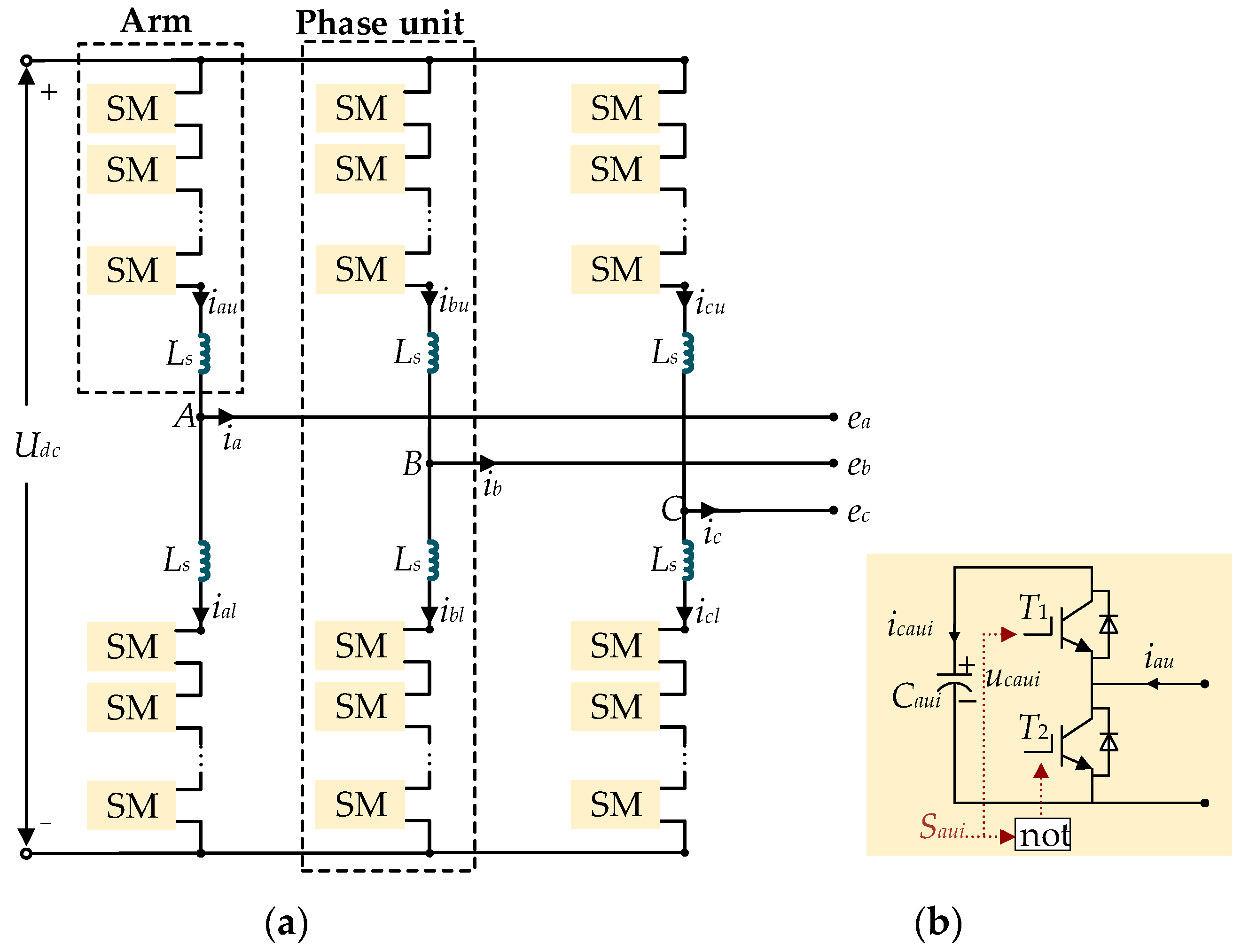
Figure 1a shows the MMC, which includes the upper arms and lower arms for phase A, B and C. An inductor Ls and N SMs are included in each arm. The circuit structure of the SMi (i = 1, 2, …, N) is composed of a SM capacitor C, switches T1, T2 and diodes D1, D2, as shown in Figure 1b. The switches of the SMi are controlled by the switching signal Saui, which can be expressed as
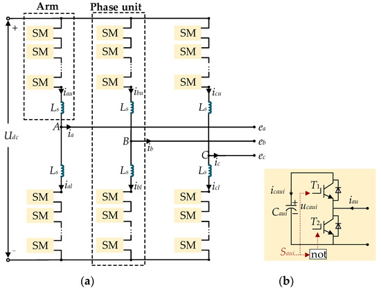
Figure 1.
(a) The MMC; (b) the SMi.
The capacitor current of the SMi is
where iau is the upper arm current.
The operation mode of the SMi is determined by iau and Saui, which is shown in Table 1. The ascending mode and the descent mode of the SMi are defined as shown in Table 1. Under the ascending mode of the SMi in Table 1, the current iau > 0. As shown in Figure 1, if Saui = 1, the capacitor voltage ucaui of the SMi is increased; if Saui = 0, the ucaui of the SMi is unchanged. Under the descent mode of the SMi in Table 1, the arm current iau ≤ 0. If Saui = 1, the ucaui decreases; if Saui = 0, the ucaui of the SMi is unchanged.

Table 1.
Operation modes of SMi.
2.2. Conventional VBC
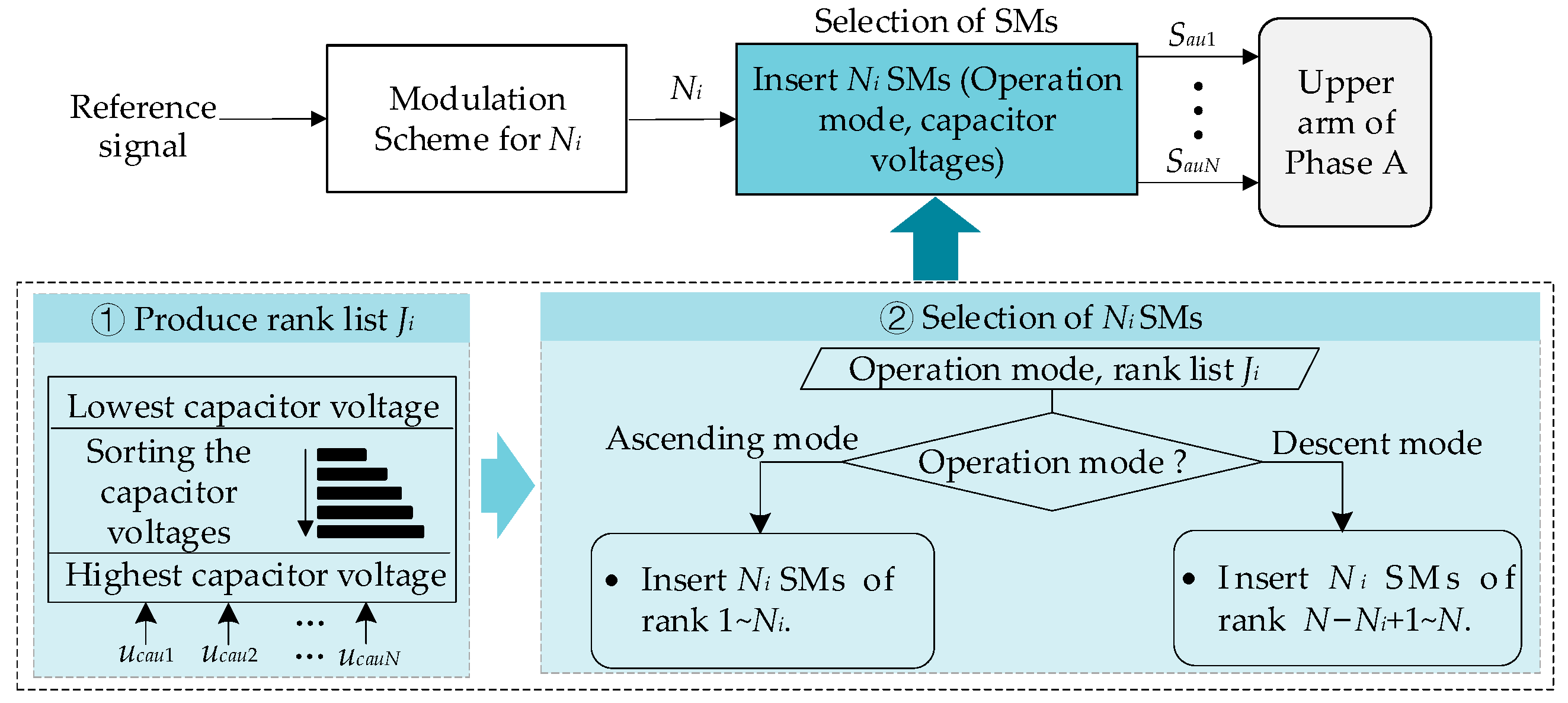
Figure 2 shows the conventional VBC [27,28,29]. The reference signal is generated based on the closed-loop control [30]. Under the modulation process, the Ni SMs should be inserted according to the reference signal.
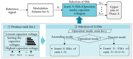
Figure 2.
Conventional voltage balancing control.
Capacitor voltages ucau1∼ucauN are sorted in order from lowest to highest voltages to generate the rank list of the SMs. Then, the rank Ji (i = 1, 2 …, n) of the SMi can be obtained, where Ji = 1 if the voltage ucaui is the lowest and Ji = N if the voltage ucaui is the highest. Combining with the rank list Ji and the operation mode, the selection of Ni SMs can be achieved. In the ascending mode, the Ni SM capacitors with the rank 1∼Ni should be inserted; in the descent mode, the Ni SM capacitors with the rank N − Ni + 1∼N should be inserted. As a result, the switching signals Sau1∼SauN in the arm can be produced and the ucau1∼ucauN can be kept balanced.
3. Effect Analysis of Measurement Offset Error on Capacitance Monitoring
Considering the measurement offset error, the measured value ûcaui of the capacitor voltage ucaui and the measured value arm current iau can be represented as
where baui_u indicates the offset error of the SM voltage sensor of the SMi and bau_i indicate the offset error of the arm current sensor. ucaui is the actual capacitor voltage of the SMi. iau is the actual arm current.
The SM capacitance Caui shown in Figure 1b can be expressed as
where ucaui and ucaui0 are the instantaneous SM capacitor voltage and initial capacitor voltage, respectively.
According to (4), in the conventional capacitance monitoring for MMCs [19,20], the capacitance Caui can be estimated as Caui_es
where is the measured value of ucaui. is the measured value of ucaui0.
Due to the chemical process and aging effect, capacitance decreases quite slowly. Therefore, the capacitance is monitored once a week or month, and each SM capacitance can be monitored with a short interval [16,20]. In the short interval, the offset error bau_i can be considered as a constant value. Based on (4) and (5), the difference between the capacitance Caui_es and Caui can be expressed as
It can be seen that the measurement offset error baui_u of the SM capacitor voltage sensor does not influence the accuracy of estimation. However, the accuracy of estimated capacitance is related to the measurement offset error bau_i of the current sensor. The accuracy of estimated Caui_es will reduce along with the increase in |bau_i|, and the accuracy of estimated Caui_es will increase along with the reduction in |bau_i|, as shown in Table 2. The symbol “↑” indicates an increase and the symbol “↓“ indicates a decrease.
Table 2.
Relationship between |bau_i| and accuracy of estimated Caui_es.
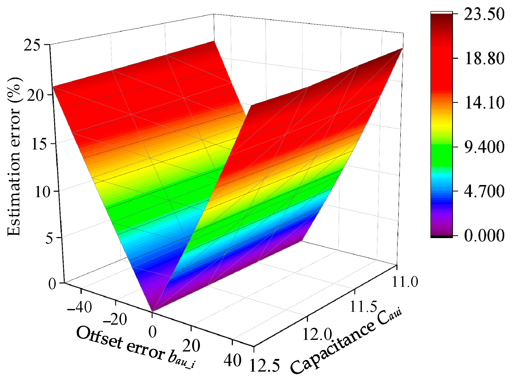
Figure 3 shows the capacitance estimation error under various measurement offset error bau_i and various capacitance Caui based on (4), which is derived from the simulation model of Section 5. As shown in Section 5, under the conventional capacitance monitoring method, for the various Caui, along with the increase in |bau_i|, the error of capacitance estimation increases; along with the reduction in |bau_i|, the error of capacitance estimation reduces, which is consistent with the analysis of Table 2.

Figure 3.
The relationship between the capacitance estimation error, bau_i and Caui in the conventional capacitance monitoring method.
4. Proposed SM Capacitance Monitoring Strategy Based on Offset Error Compensation for MMCs
4.1. Proposed Capacitance Monitoring Approach Based on Offset Error Compensation
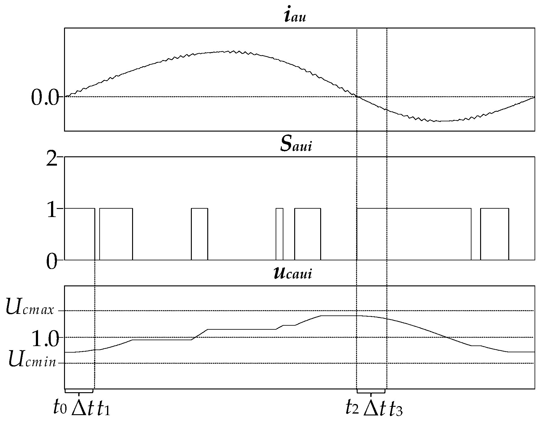
In order to eliminate the impact of the sensor offset error bau_i on the monitoring of Caui, a capacitance monitoring approach based on the offset error compensation is proposed. Under the proposed approach, the arm current iau, switching signal Saui and the SM capacitor voltage ucaui for the monitored SMi in one fundamental period T are shown in Figure 4. In the proposed approach, the period t0~t1 of the ascending mode and the period t2~t3 of the descent mode in Figure 4 are selected to estimate the capacitance, where the switching signal Saui = 1 during both the period t0~t1 and the period t2~t3.
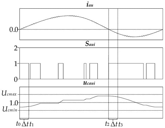
Figure 4.
The upper arm current iau, switching signal Saui and capacitor voltage ucaui of MMCs under the proposed approach.
Based on (5), the capacitance Caui_es1 estimated in the ascending mode t0~t1 and the capacitance Caui_es2 estimated in the descent mode t2~t3 can be, respectively, expressed as
Combining (4)~(6), Equations (7) and (8) can be, respectively, rewritten as
Combining (9) and (10), the capacitance Caui can be expressed as
From (11), it can be observed that Caui contains the error term caused by the measurement offset error bau_i. In order to eliminate the adverse impact of the offset error bau_i on the monitoring result, combining (11), a capacitance monitoring approach based on offset error compensation is proposed, where the condition (12) is satisfied.
Substituting (12) into (11), the capacitance Caui can be rewritten as
From (13), it can be seen that capacitance Caui does not contain the error term induced by the measurement offset error bau_i when the condition (12) is satisfied. Comparing (11) and (13), it can be seen that the proposed approach can eliminate the adverse impact of the offset error bau_i on the result of capacitance estimation.
4.2. Proposed VCV-Based VBC
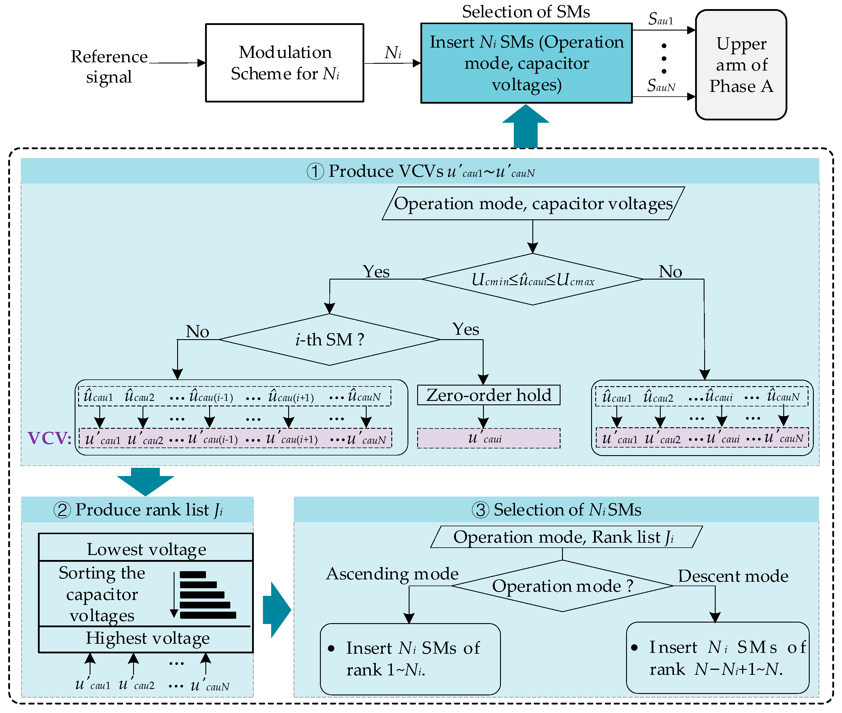
As shown in Figure 5, to achieve the proposed capacitance monitoring approach based on offset error compensation, a virtual capacitor voltage (VCV)-based VBC is proposed to choose the inserted SMs. The proposed VCV-based VBC not only ensures that the capacitor voltages remain balanced, and that ucaui does not exceed the limit, but also ensures that the switching signal for the monitored SMi is switched as few times as possible, both in the ascending mode and in the descent mode, which facilitates the selection of the periods t0~t1 and t2~t3 in Figure 4, so as to realize the proposed monitoring approach based on the offset error compensation.
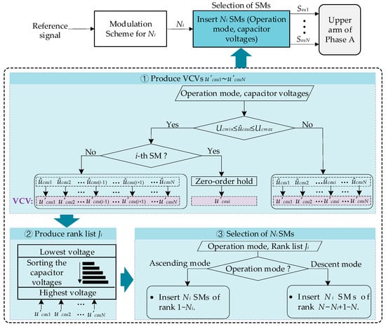
Figure 5.
Proposed VCV-based voltage-balancing control.
The capacitor voltages should be controlled within the range of the maximum voltage Ucmax and the minimum voltage Ucmin, as shown in Figure 4. In Figure 5, the capacitance Caui of the SMi is estimated, the inserted SMs can be determined according to the operation mode and the ranks of VCVs, as follows.
- (1)
- Ucmin ≤ ûcaui ≤ Ucmax: the VCVs u′cau1∼u′cauN (except for u′caui in the monitored SMi) are, respectively, set to ûcau1∼ûcauN (except for ûcaui). For the SMi, the zero-order hold is introduced to obtain the virtual capacitor voltage u′caui, as shown in Figure 5, which can reduce the update frequency of the voltage ûcaui, and thus reduces the update frequency of the rank Ji of the SMi;
- (2)
- ûcaui > Ucmax or ûcaui < Ucmin: the VCVs u′cau1∼u′cauN are set to ûcau1∼ûcauN, respectively.
Based on the operation mode and the ranks of the VCVs, the selection of the inserted SMs can be decided. In the ascending mode, the Ni SM capacitors with the rank 1∼Ni should be inserted; in the descent mode, the Ni SM capacitors with the rank N − Ni + 1∼N should be inserted.
4.3. Proposed Capacitance Monitoring Strategy
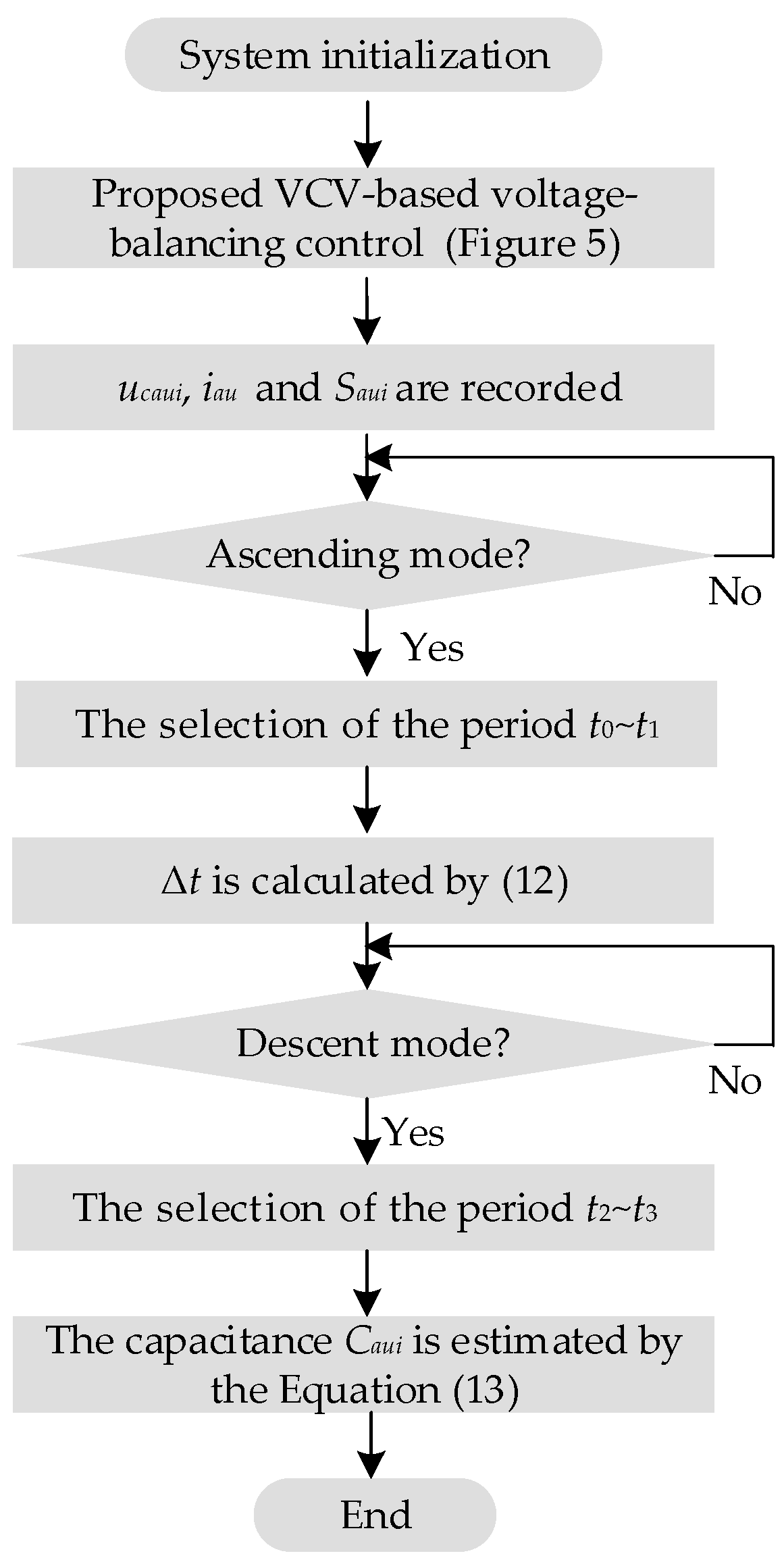
According to the proposed capacitance monitoring approach based on offset error compensation in Section 4.1 and the VCV-based voltage-balancing control in Section 4.2, the capacitance monitoring strategy based on offset error compensation of the arm current sensor is proposed, where capacitance Caui of the SMi is monitored and the proposed VCV-based voltage-balancing control is implemented, as shown in Figure 6. In the proposed strategy, the voltage ucaui of the capacitor of the SMi, the current iau and the switching signal Saui of the SMi should be recorded. In the ascending mode, the period t0~t1 is selected, where the selection criterion is the switching signal Saui = 1 for the period t0~t1, as shown in Figure 4. In addition, the interval from t0 to t1 should be as long as possible, to improve the accuracy of capacitance monitoring. According to the selected t0 and t1, the Δt can be calculated by Equation (12). In the descent mode, based on the Δt and (12), the period t2~t3 of Saui = 1 is selected. According to the iau and Saui during t0~t1 and t2~t3, ucaui(t0), ucaui(t1), ucaui(t2) and ucaui(t3), the capacitance Caui can be estimated by Equation (13).
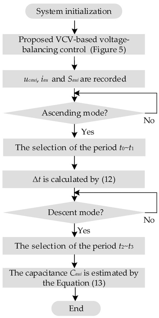
Figure 6.
Proposed capacitance monitoring strategy.
5. Simulation Studies
An MMC model is built by the simulation software PLECS 4.5.6 to verify the proposed strategy. The parameters are shown in Table 3.
Table 3.
Simulation parameters.
5.1. MMC without Measurement Offset Error bau_i
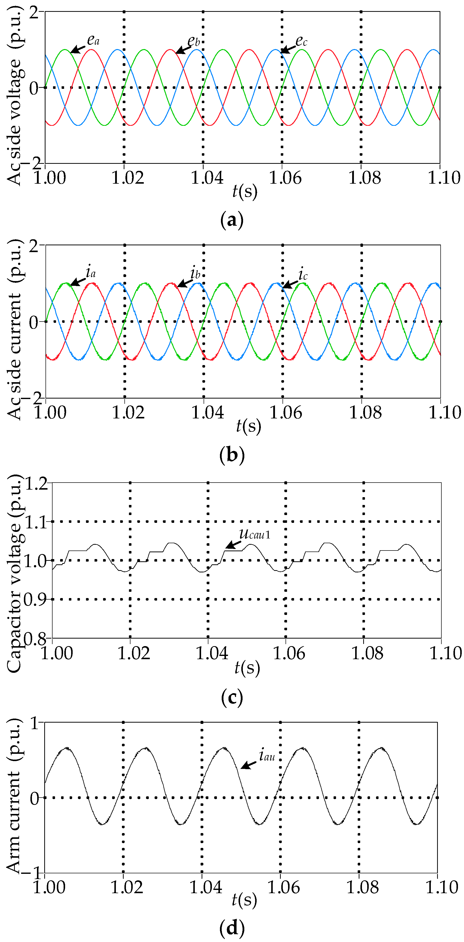
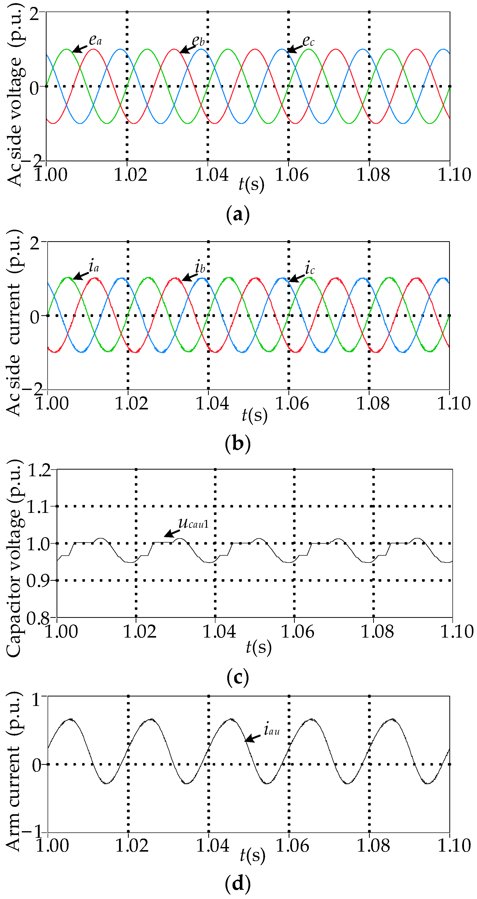
Figure 7 shows the simulated waveforms of the MMC under the proposed capacitance monitoring strategy. The offset error bau_i is not introduced into the measurement of the arm current iau, where bau_i = 0. Figure 7a and Figure 7b show the AC side voltages ea, eb, ec and the currents ia, ib, ic, respectively. Figure 7c shows the capacitor voltage ucau1. Figure 7d shows the arm current iau.
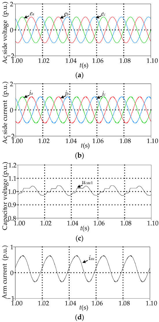
Figure 7.
Simulated waveforms of the MMC without the offset error bau_i under the proposed strategy: (a) ea, eb, ec; (b) ia, ib, ic; (c) ucau1; (d) iau.
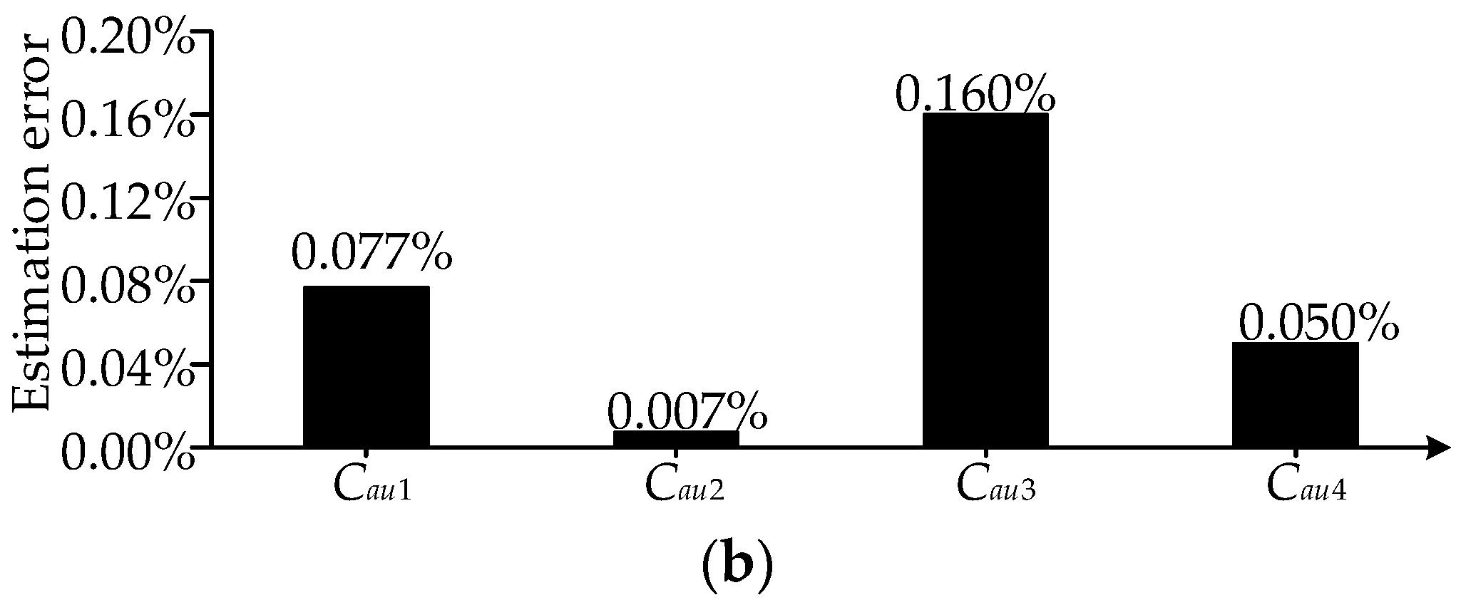
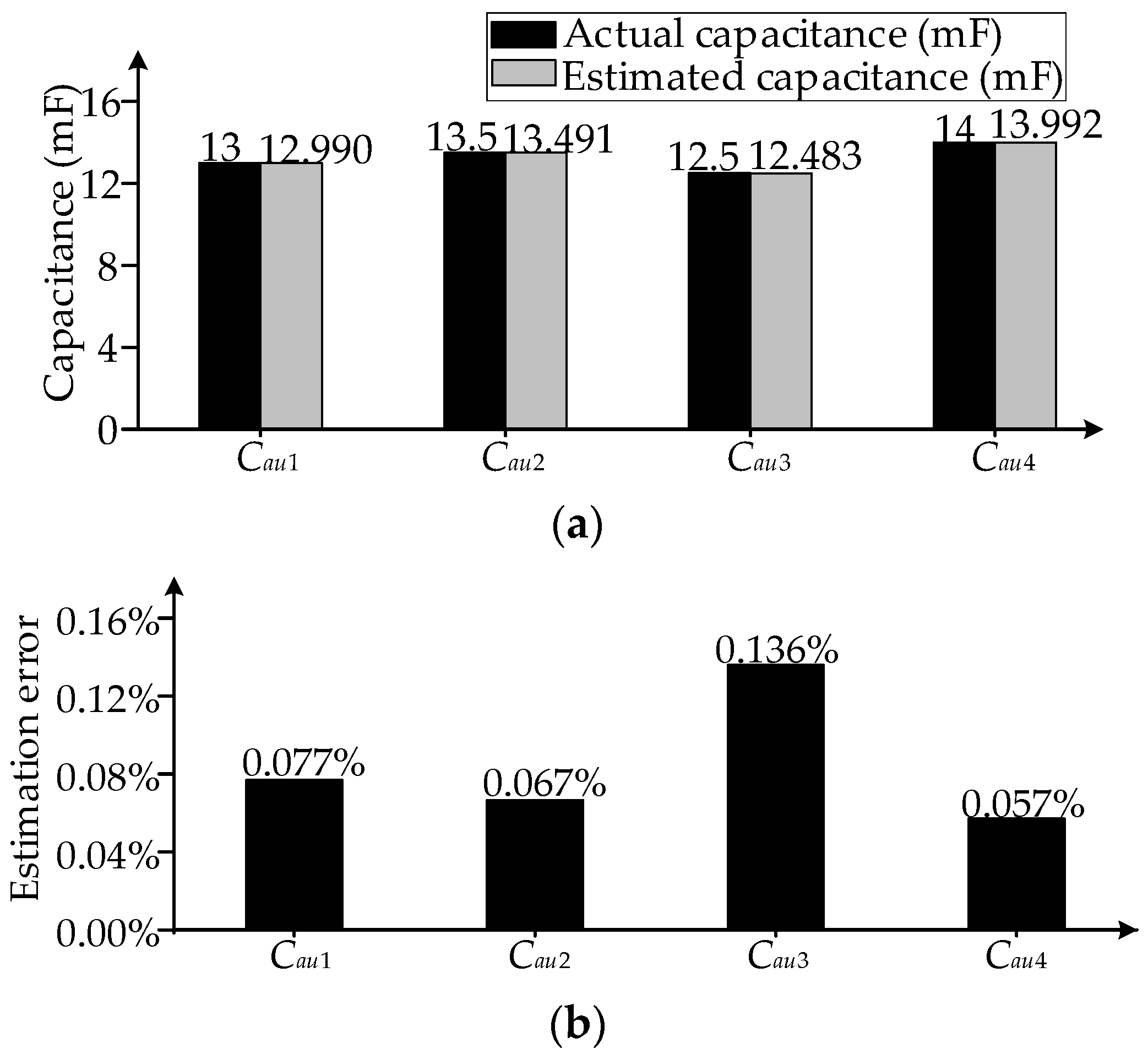
Under the conventional capacitance monitoring method on the basis of (4), the capacitance Cau1~Cau4 is estimated, as shown in Figure 8. Figure 8a shows the actual and estimated capacitance of Cau1~Cau4. Figure 8b shows the estimation errors of Cau1~Cau4. Under the proposed strategy, the capacitance Cau1~Cau4 is estimated, as shown in Figure 9a,b. From Figure 8 and Figure 9, it can be observed that the estimation errors are small under the conventional method and the proposed strategy when the offset error is not introduced into the measurement of the upper arm current iau.
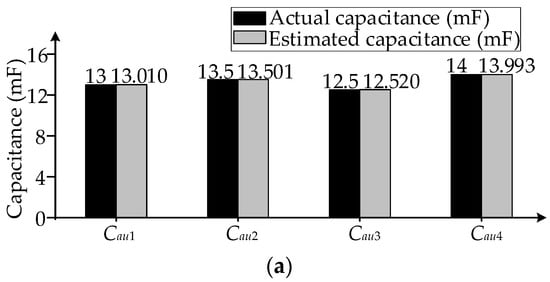

Figure 8.
Simulated waveforms of the MMC without the offset error bau_i under the conventional capacitance monitoring method: (a) the actual and estimated capacitance of Cau1~Cau4; (b) estimation error.
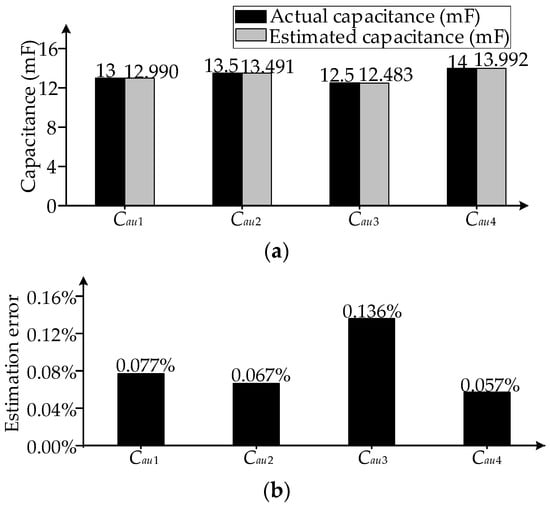
Figure 9.
Simulation results without the offset error bau_i under the proposed strategy: (a) the actual and estimated capacitance of Cau1~Cau4; (b) estimation error.
Without introducing the offset error bau_i, comparing the MMC with and without the proposed monitoring strategy in Table 4, the total harmonic distortion (THD) of the AC side current ia is almost the same. Therefore, the proposed strategy has no effect on the MMC output waveforms.
Table 4.
Simulation results of the THD of the output current.
5.2. MMC with Measurement Offset Error bau_i
Figure 10 shows the simulated waveforms under the proposed strategy. The offset error is introduced into the measurement of the arm current iau, where bau_i = 27.22 A. Figure 10a and Figure 10b show the AC side voltages ea, eb, ec and the currents ia, ib, ic, respectively. Figure 10c shows the capacitor voltage ucau1 in the SM1. Figure 10d shows the arm current iau.
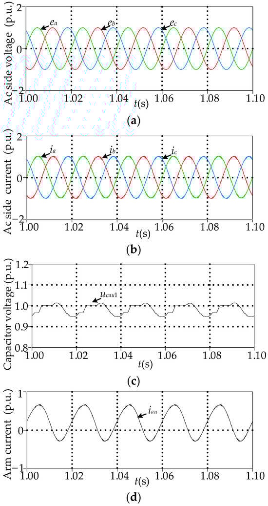
Figure 10.
Simulated waveforms of the MMC with the offset error bau_i under the proposed strategy: (a) ea, eb, ec; (b) ia, ib, ic; (c) ucau1; (d) iau.
Under the conventional capacitance monitoring method, in Figure 11a,b, the capacitance Cau1~Cau4 is estimated. Figure 11a shows the actual and estimated capacitance of Cau1~Cau4. Figure 11b shows the estimation errors of Cau1~Cau4. Under the proposed strategy, the capacitance Cau1~Cau4 is estimated, as shown in Figure 12. Comparing the conventional capacitance monitoring method in Figure 11 and the proposed strategy in Figure 12, it can be observed that the proposed strategy effectively decreases the effect of the offset error bau_i on the capacitance estimation. Additionally, the estimation errors in Figure 12b are similar to those of Figure 9b. Therefore, the capacitance monitoring results under the proposed strategy are almost unaffected by the offset error bau_i.
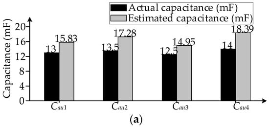
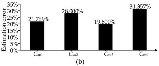
Figure 11.
Simulated results of the MMC with the offset error bau_i under the conventional capacitance monitoring method: (a) the actual and estimated capacitance of Cau1~Cau4; (b) estimation error.
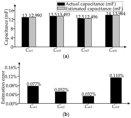
Figure 12.
Simulation results of the MMC with the offset error bau_i under the proposed strategy: (a) the actual and estimated capacitance of Cau1~Cau4; (b) estimation error.
In the case of introducing the offset error bau_i, comparing the MMC with and without the proposed strategy, the THD of ia is almost the same, as shown in Table 4. Therefore, the proposed strategy has no effect on the MMC output waveforms.
6. Experimental Studies
The MMC experimental platform is built. Figure 13 shows the MMC experimental platform, and Table 5 shows the system parameters.
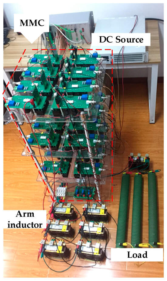
Figure 13.
The MMC experimental platform.
Table 5.
Experimental parameters.
6.1. MMC without Measurement Offset Error bbl_i
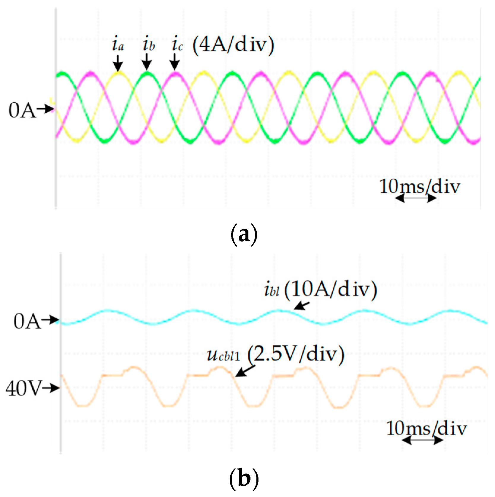
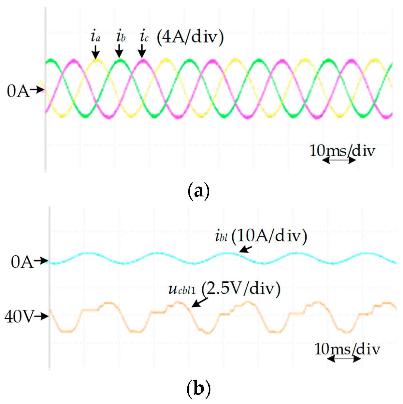
Figure 14 shows the simulated waveforms under the proposed capacitance monitoring strategy. The offset error bbl_i is not introduced into the measurement of the arm current ibl, where bbl_i = 0. Figure 14a shows the AC side currents ia, ib, ic. Figure 14b shows the current ibl and the capacitor voltage ucbl1 in SM1.
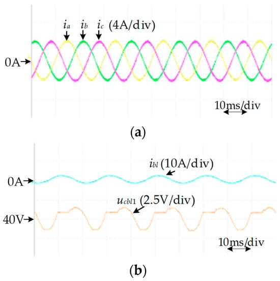
Figure 14.
Experimental waveforms of the MMC without the offset error bbl_i under the proposed strategy: (a) ia, ib, ic; (b) ibl and ucbl1.
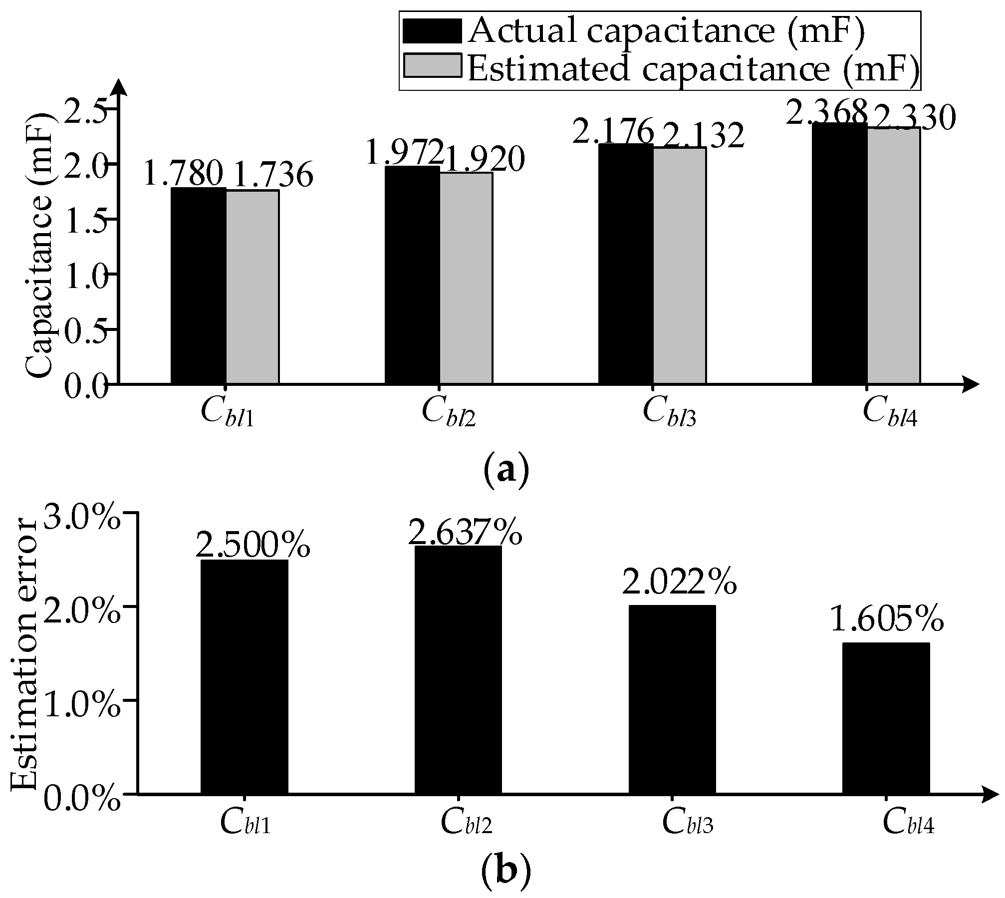
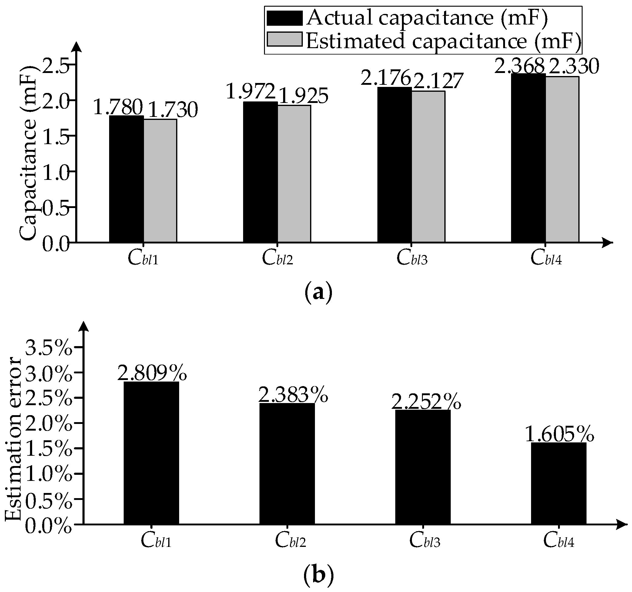
Under the conventional capacitance monitoring method, in Figure 15a,b, the capacitance Cbl1~Cbl4 is estimated. Figure 15a shows the actual and estimated capacitance of Cbl1~Cbl4. Figure 15b shows the estimation errors of Cbl1~Cbl4. Under the proposed strategy, the capacitance Cbl1~Cbl4 is estimated, as shown in Figure 16a,b. As shown in Figure 15 and Figure 16, the capacitance estimation errors are small under the conventional method and the proposed strategy when the offset error bbl_i is not introduced into the measurement of ibl.

Figure 15.
Experimental results of the MMC without the offset error bbl_i under the conventional capacitance monitoring method: (a) the actual and estimated capacitance of Cbl1~Cbl4; (b) estimation error.

Figure 16.
Experimental results of the MMC without the offset error bbl_i under the proposed strategy: (a) the actual and estimated capacitance of Cbl1~Cbl4; (b) estimation error.
Without introducing the offset error bbl_i, comparing the MMC with and without the proposed strategy, the THD of the AC side current ib is almost the same, as shown in Table 6. Therefore, the proposed strategy has no effect on the MMC output waveforms.
Table 6.
Simulation results of the THD of the AC side current.
6.2. MMC with Measurement Offset Error bbl_i
Figure 17 shows the simulated waveforms under the proposed strategy, where the capacitance Cbl1 is monitored. The offset error bbl_i is introduced into the measurement of the current ibl, where bbl_i = 0.2 A. Figure 17a shows the AC side currents ia, ib, ic. Figure 17b shows the arm current ibl and the capacitor voltage ucbl1 in SM1.

Figure 17.
Experimental waveforms of the MMC with the offset error bbl_i under the proposed strategy: (a) ia, ib, ic; (b) ibl and ucbl1.
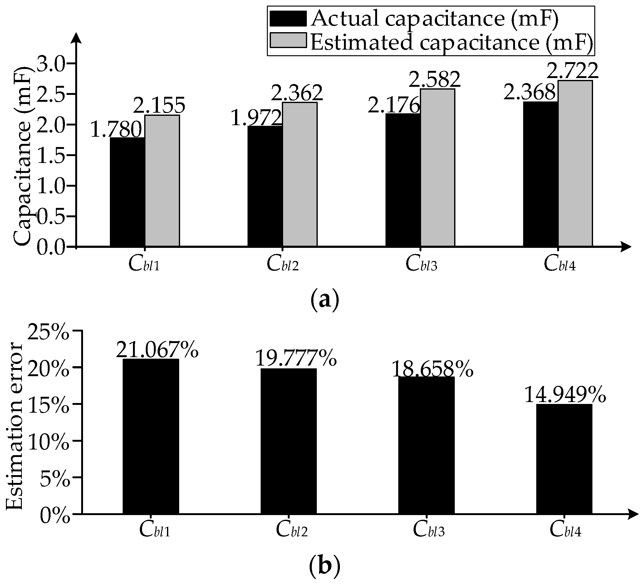
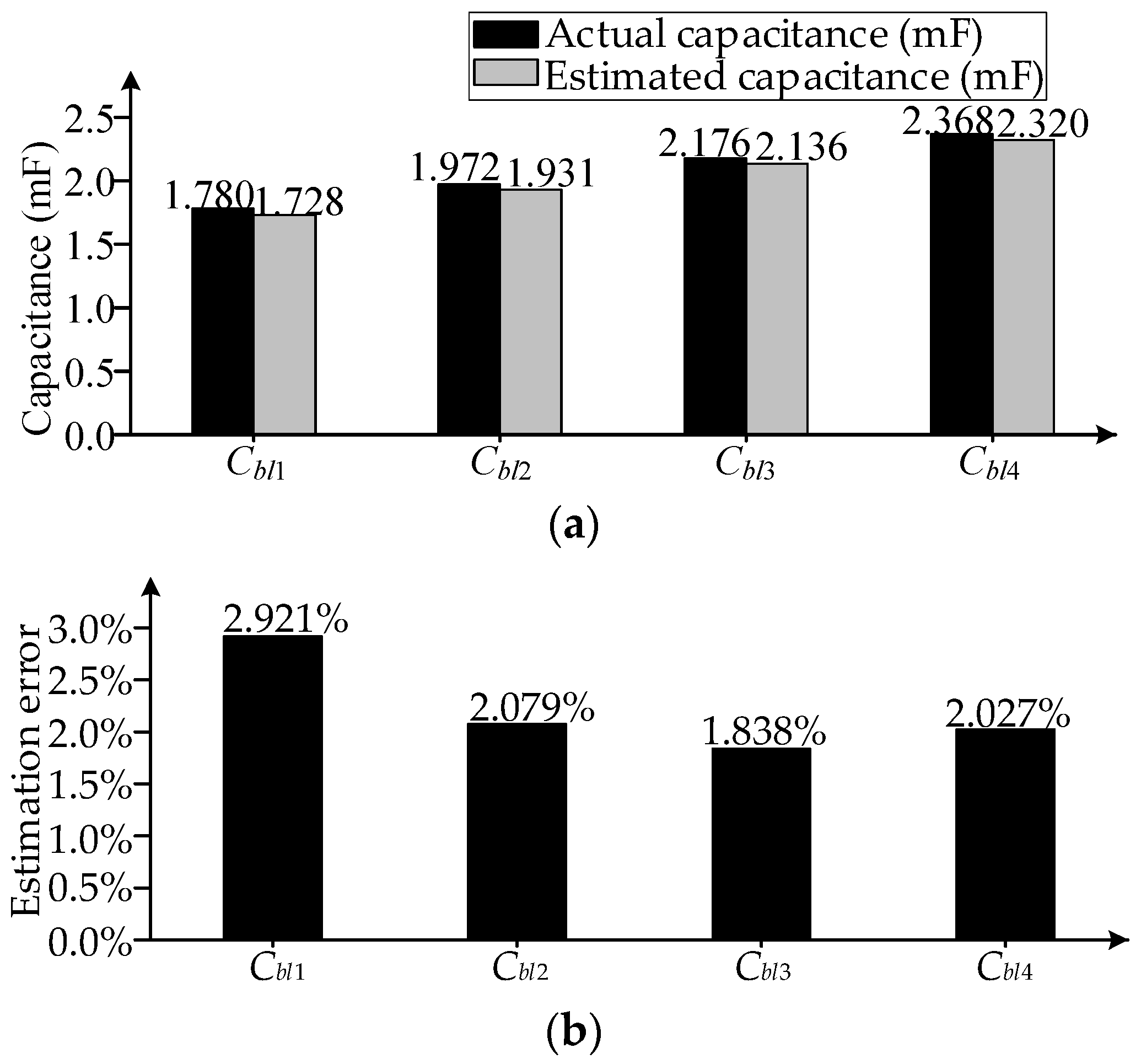
Under the conventional capacitance monitoring method, in Figure 18a,b, the capacitance Cbl1~Cbl4 is estimated. Figure 18a shows the actual and estimated capacitance of Cbl1~Cbl4. Figure 18b shows the estimation errors of Cbl1~Cbl4. Under the proposed strategy, the capacitance Cbl1~Cbl4 is estimated, as shown in Figure 19a,b. Comparing the conventional capacitance monitoring method in Figure 18 and the proposed strategy in Figure 19, it can be observed that the adverse impact of the sensor offset error bbl_i on the capacitance estimation can be decreased by the proposed strategy. Additionally, the estimation errors in Figure 19b are similar to those of Figure 16b. Therefore, the capacitance monitoring results under the proposed capacitance monitoring strategy based on offset error compensation of the arm current sensor are almost unaffected by the offset error bbl_i.

Figure 18.
Experimental results of the MMC with the offset error bbl_i under the conventional capacitance monitoring method: (a) the actual and estimated capacitance of Cbl1~Cbl4; (b) estimation error.

Figure 19.
Experimental results of the MMC with the offset error bbl_i under the proposed strategy: (a) the actual and estimated capacitance of Cbl1~Cbl4; (b) estimation error.
In the case of introducing the offset error bbl_i, comparing the MMC with and without the proposed strategy, the THD of ib is almost the same, as shown in Table 6. Therefore, the proposed strategy has no effect on the MMC output waveforms.
7. Discussion
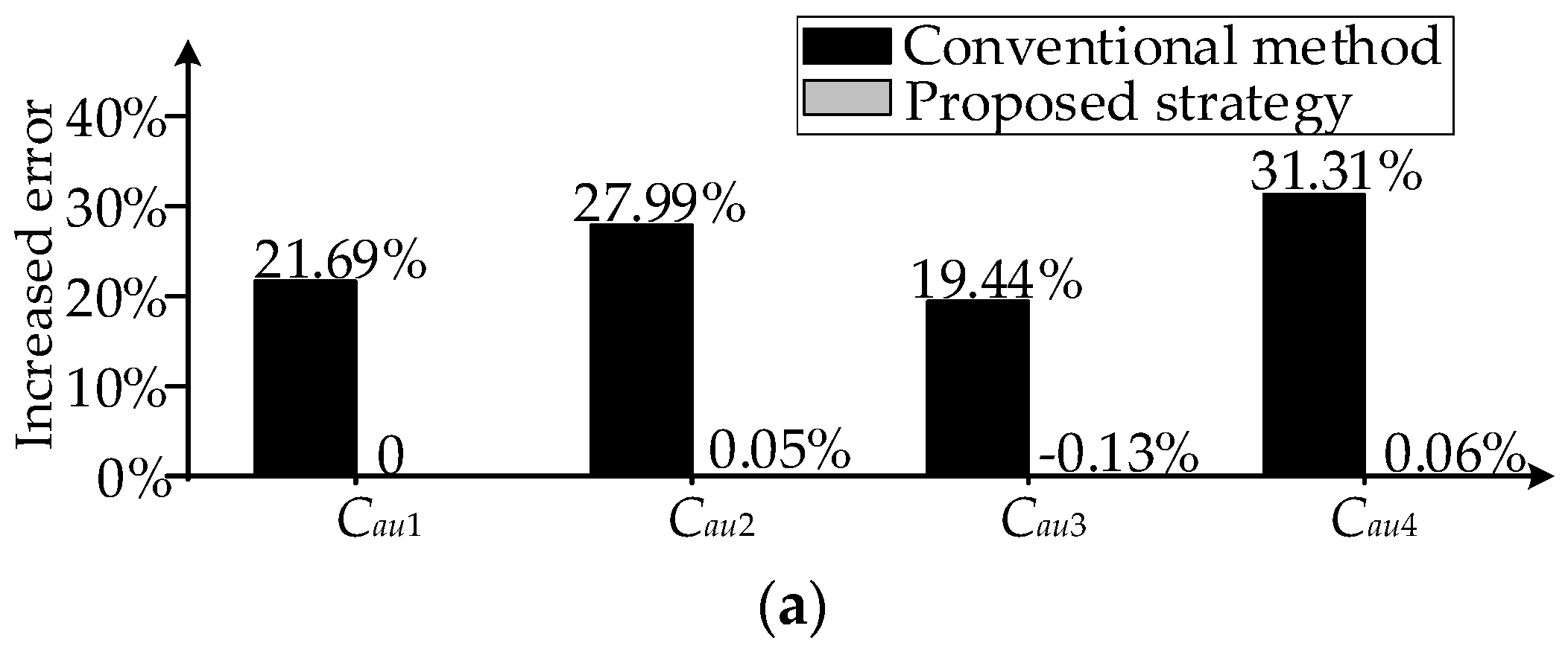
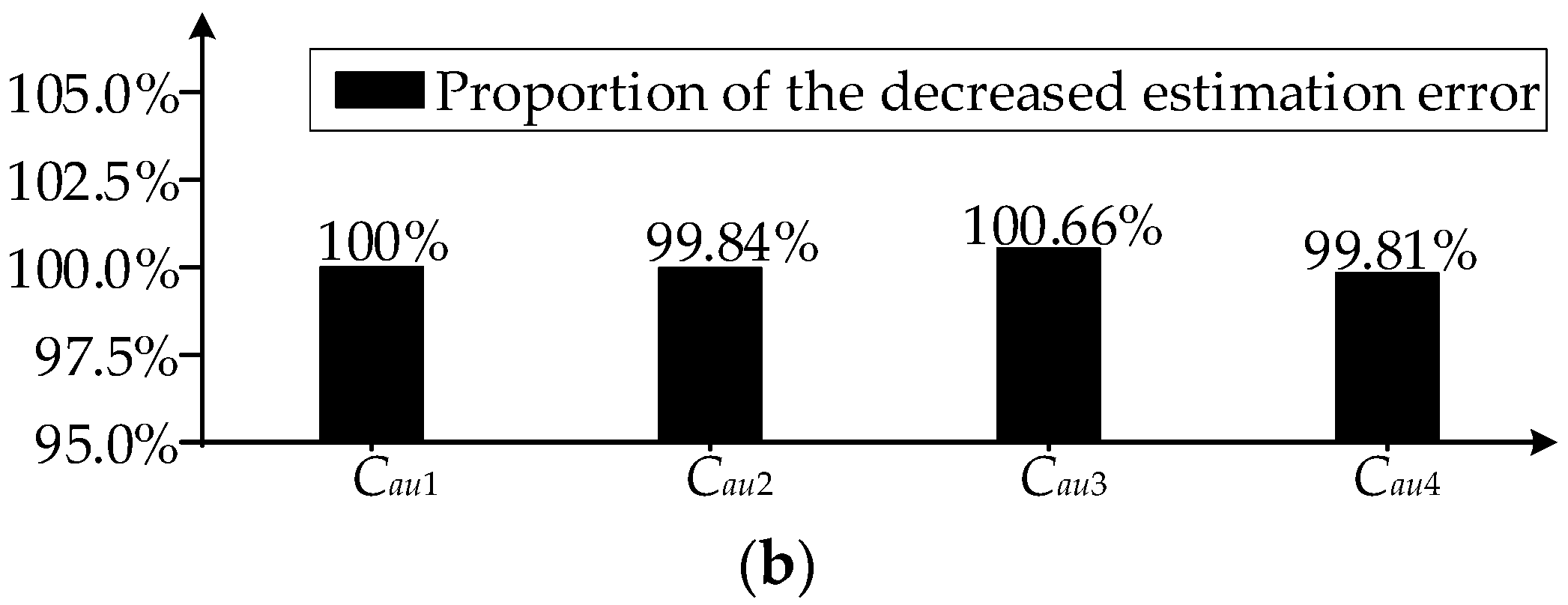
Combining the simulation results of Figure 8, Figure 11 and Figure 12 in the simulation studies, and comparing the MMC without the offset error under the conventional capacitance monitoring method, the increased estimation errors for the MMC with the offset error under the conventional method and proposed strategy are shown in Figure 20a. According to Figure 20a, comparing the conventional method, the proportion of the decreased estimation error under the proposed strategy is shown in Figure 20b.
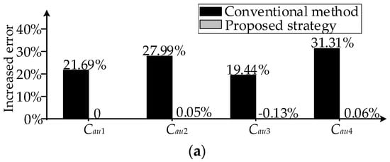

Figure 20.
Simulation results for the MMC: (a) increased estimation errors under the conventional method and proposed strategy; (b) proportion of the decreased estimation error under the proposed strategy.
Combining the experimental results of Figure 15, Figure 18 and Figure 19 in the experimental studies, and comparing the MMC without the offset error under the conventional capacitance monitoring method, the increased estimation errors for the MMC with the offset error under the conventional method and proposed strategy are shown in Figure 21a. According to Figure 21a, comparing the conventional method, the proportion of the decreased estimation error under the proposed strategy is shown in Figure 21b.
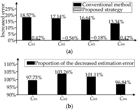
Figure 21.
Experimental results for the MMC: (a) increased estimation errors under the conventional method and proposed strategy; (b) proportion of the decreased estimation error under the proposed strategy.
As shown in Figure 20 and Figure 21, it can be seen that the proportion of the decreased estimation error is greater than 90% under the proposed strategy in the simulation and experimental results. Therefore, according to the simulation and experimental results, the proposed strategy eliminates more than 90% of the estimation error caused by the offset error.
8. Conclusions
In this paper, the effect of the measurement offset error of the arm current sensor on the capacitance monitoring of the MMC is analyzed, where the measurement offset error causes the increase in the estimation error in the estimation of the SM capacitance, affecting the capacitance monitoring accuracy. A capacitor monitoring strategy based on offset error compensation is proposed, where two reasonable capacitor monitoring periods are selected in one fundamental period under the proposed VCV-based VBC to compensate for the offset error’s impact on the capacitance estimation. The proposed strategy eliminates more than 90% of the estimation error caused by the offset error in the simulation and experimental results. Therefore, the proposed strategy almost eliminates the adverse impact of the offset error of the arm current sensor on the capacitance monitoring and ensures low estimation errors for the SM capacitance monitoring. Simulation and experiment results are conducted to confirm the effectiveness of the proposed strategy.
Author Contributions
Conceptualization, H.J. and F.D.; formal analysis, H.J.; methodology, H.J.; software, H.J.; validation, H.J.; writing—original draft, H.J.; supervision, F.D.; writing—review and editing, H.J., F.D., H.L., J.T., Y.L. and G.L. All authors have read and agreed to the published version of the manuscript.
Funding
This research was funded by the Science and Technology Projects of Jiangsu Province under Project BE2022016.
Data Availability Statement
Data are contained within the article.
Conflicts of Interest
Authors Jie Tian, Yu Lu and Gang Li were employed by the company NR Electric Company, Ltd. The remaining authors declare that the research was conducted in the absence of any commercial or financial relationships that could be construed as a potential conflict of interest.
References
- Gao, X.; Pang, Y.; Xia, J.; Chai, N.; Tian, W.; Rodriguez, J.; Kennel, R. Modulated Model Predictive Control of Modular Multilevel Converters Operating in a Wide Frequency Range. IEEE Trans. Ind. Electron. 2023, 70, 4380–4391. [Google Scholar] [CrossRef]
- Liu, J.; Dong, D. A Flying Capacitor Hybrid Modular Multilevel Converter with Reduced Number of Submodules and Power Losses. IEEE Trans. Ind. Electron. 2023, 70, 3293–3302. [Google Scholar] [CrossRef]
- Bagheri-Hashkavayi, M.; Barakati, S.M.; Yousofi-Darmian, S.; Barahouei, V. Improved Sensor Reduction Method in Modular Multilevel Converters with Open-Loop Controller Based on Arms Energy Estimation. IEEE Trans. Power Deliv. 2022, 37, 5003–5013. [Google Scholar] [CrossRef]
- Marzo, I.; Sanchez-Ruiz, A.; Barrena, J.A.; Abad, G.; Muguruza, I. Power Balancing in Cascaded H-Bridge and Modular Multilevel Converters under Unbalanced Operation: A Review. IEEE Access 2021, 9, 110525–110543. [Google Scholar] [CrossRef]
- Ji, S.; Huang, X.; Palmer, J.; Wang, F.; Tolbert, L.M. Modular Multilevel Converter (MMC) Modeling Considering Submodule Voltage Sensor Noise. IEEE Trans. Power Electron. 2021, 36, 1215–1219. [Google Scholar] [CrossRef]
- Zhao, Z.; Davari, P.; Lu, W.; Wang, H.; Blaabjerg, F. An Overview of Condition Monitoring Techniques for Capacitors in DC-Link Applications. IEEE Trans. Power Electron. 2021, 36, 3692–3716. [Google Scholar] [CrossRef]
- Younis, T.; Mattavelli, P.; Toigo, I.; Corradin, M. Three-Phase Modular Multilevel Converter with Optimized Capacitor Sizing for Low-Voltage Applications. IEEE Trans. Power Electron. 2021, 36, 13930–13943. [Google Scholar] [CrossRef]
- Li, Y.; Zheng, W.; Xu, Q. On-Line Monitoring Method of Submodule in MMC Based on Kalman Filter Algorithm. In Proceedings of the 2020 Asia Energy and Electrical Engineering Symposium (AEEES), Chengdu, China, 29–31 May 2020; pp. 386–390. [Google Scholar]
- Yin, C.; Deng, F.; Zhao, F.; Yu, Q. Condition Monitoring Strategy for Modular Multilevel Converters with Improved Accuracy. In Proceedings of the 10th Renewable Power Generation Conference (RPG 2021), Online Conference, 14–15 October 2021; pp. 762–770. [Google Scholar]
- Yao, R.; Li, H.; Lai, W.; Bahman, A.S.; Iannuzzo, F. Lifetime Analysis of Metallized Polypropylene Capacitors in Modular Multilevel Converter Based on Finite Element Method. IEEE J. Emerg. Sel. Top. Power Electron. 2020, 9, 4248–4259. [Google Scholar] [CrossRef]
- Polanco, I.; Dujic, D. Condition Health Monitoring of Modular Multilevel Converter Submodule Capacitors. IEEE Trans. Power Electron. 2022, 37, 3544–3554. [Google Scholar] [CrossRef]
- Zhang, J.; Hu, X.; Xu, S.; Zhang, Y.; Chen, Z. Fault Diagnosis and Monitoring of Modular Multilevel Converter with Fast Response of Voltage Sensors. IEEE Trans. Ind. Electron. 2020, 67, 5071–5080. [Google Scholar] [CrossRef]
- Amaral, A.M.R.; Cardoso, A.J.M. An Experimental Technique for Estimating the ESR and Reactance Intrinsic Values of Aluminum Electrolytic Capacitors. In Proceedings of the 2006 IEEE Instrumentation and Measurement Technology Conference Proceedings, Sorrento, Italy, 24–27 April 2006; pp. 1820–1825. [Google Scholar]
- Amaral, A.M.R.; Cardoso, A.J.M. A Simple Offline Technique for Evaluating the Condition of Aluminum-Electrolytic-Capacitors. IEEE Trans. Ind. Electron. 2009, 56, 3230–3237. [Google Scholar] [CrossRef]
- Wang, Z.; Zhang, Y.; Wang, H.; Blaabjerg, F. Capacitor Condition Monitoring Based on the DC-Side Start-Up of Modular Multilevel Converters. IEEE Trans. Power Electron. 2020, 35, 5589–5593. [Google Scholar] [CrossRef]
- Wang, H.; Wang, H.; Wang, Z.; Zhang, Y.; Pei, X.; Kang, Y. Condition Monitoring for Submodule Capacitors in Modular Multilevel Converters. IEEE Trans. Power Electron. 2019, 34, 10403–10407. [Google Scholar] [CrossRef]
- Agarwal, N.; Ahmad, M.W.; Anand, S. Quasi-Online Technique for Health Monitoring of Capacitor in Single-Phase Solar Inverter. IEEE Trans. Power Electron. 2018, 33, 5283–5291. [Google Scholar] [CrossRef]
- Ronanki, D.; Williamson, S.S. Failure Prediction of Submodule Capacitors in Modular Multilevel Converter by Monitoring the Intrinsic Capacitor Voltage Fluctuations. IEEE Trans. Ind. Electron. 2020, 67, 2585–2594. [Google Scholar] [CrossRef]
- Jo, Y.-J.; Nguyen, T.H.; Lee, D.-C. Condition Monitoring of Submodule Capacitors in Modular Multilevel Converters. In Proceedings of the 2014 IEEE Energy Conversion Congress and Exposition (ECCE), Pittsburgh, PA, USA, 14–18 September 2014; pp. 2121–2126. [Google Scholar]
- Deng, F.; Wang, Q.; Liu, D.; Wang, Y.; Cheng, M.; Chen, Z. Reference Submodule Based Capacitor Monitoring Strategy for Modular Multilevel Converters. IEEE Trans. Power Electron. 2019, 34, 4711–4721. [Google Scholar] [CrossRef]
- Wang, Z.; Zhang, Y.; Wang, H.; Blaabjerg, F. A Reference Submodule Based Capacitor Condition Monitoring Method for Modular Multilevel Converters. IEEE Trans. Power Electron. 2020, 35, 6691–6696. [Google Scholar] [CrossRef]
- Geng, Z.; Han, M.; Zhou, G. Switching Signals Based Condition Monitoring for Submodule Capacitors in Modular Multilevel Converters. IEEE Trans. Circuits Syst. II Express Briefs 2021, 68, 2017–2021. [Google Scholar] [CrossRef]
- Xiao, Q.; Wang, H.; Jin, Y.; Jia, H.; Mu, Y.; Zhu, J.; Teodorescu, R.; Blaabjerg, F. Submodule Capacitance Monitoring Approach for the MMC with Asymptotically Converged Error. IEEE Trans. Ind. Electron. 2024, 71, 4330–4339. [Google Scholar] [CrossRef]
- Xia, H.; Zhang, Y.; Chen, M.; Lai, W.; Luo, D.; Wang, H. Capacitor Condition Monitoring for Modular Multilevel Converter Based on Charging Transient Voltage Analysis. IEEE Trans. Power Electron. 2023, 38, 3847–3856. [Google Scholar] [CrossRef]
- Liu, C.; Deng, F.; Yu, Q.; Wang, Y.; Blaabjerg, F.; Cai, X. Submodule Capacitance Monitoring Strategy for Phase-Shifted Carrier Pulsewidth-Modulation-Based Modular Multilevel Converters. IEEE Trans. Ind. Electron. 2021, 68, 8753–8767. [Google Scholar] [CrossRef]
- Xie, J.; He, Y.; Xiong, Z.; Chen, Z.; Wang, Y.; Du, Y.; Pan, J. Non-Intrusive Condition Monitoring of Submodule Capacitance of Modular Multilevel Converter with Image Identification Method. In Proceedings of the 2022 IEEE Energy Conversion Congress and Exposition (ECCE), Detroit, MI, USA, 9–13 October 2022; pp. 1–6. [Google Scholar]
- Perez, M.A.; Ceballos, S.; Konstantinou, G.; Pou, J.; Aguilera, R.P. Modular Multilevel Converters: Recent Achievements and Challenges. IEEE Open J. Ind. Electron. Soc. 2021, 2, 224–239. [Google Scholar] [CrossRef]
- Zhou, L.; Chen, C.; Xiong, J.; Zhang, K. A Robust Capacitor Voltage Balancing Method for CPS-PWM-Based Modular Multilevel Converters Accommodating Wide Power Range. IEEE Trans. Power Electron. 2022, 37, 14306–14316. [Google Scholar] [CrossRef]
- Geng, Z.; Han, M.; Xia, C.; Kou, L. A Switching Times Reassignment-Based Voltage Balancing Strategy for Submodule Capacitors in Modular Multilevel HVDC Converters. IEEE Trans. Power Deliv. 2022, 37, 1215–1225. [Google Scholar] [CrossRef]
- Wang, C.; Zhang, L.; Xie, W.; Xiao, L.; Zhang, Z.; Zhang, Z.; Chen, D. Analysis and Suppression of the Frequency-Aliasing Phenomenon Related to the Sorting-Algorithm-Based Voltage-Balance Strategy in an MMC System. IEEE Trans. Power Electron. 2022, 37, 170–182. [Google Scholar] [CrossRef]


Disclaimer/Publisher’s Note: The statements, opinions and data contained in all publications are solely those of the individual author(s) and contributor(s) and not of MDPI and/or the editor(s). MDPI and/or the editor(s) disclaim responsibility for any injury to people or property resulting from any ideas, methods, instructions or products referred to in the content. |
© 2024 by the authors. Licensee MDPI, Basel, Switzerland. This article is an open access article distributed under the terms and conditions of the Creative Commons Attribution (CC BY) license (https://creativecommons.org/licenses/by/4.0/).