Article

Machine Learning Classifier for Supporting Generator’s Impedance-Based Relay Protection Functions

Department of Electrical Power Engineering, FESB, University of Split, R. Boskovica 32, HR-21000 Split, Croatia
*
Author to whom correspondence should be addressed.
Energies 2024, 17(8), 1820; https://doi.org/10.3390/en17081820
Submission received: 13 March 2024 / Revised: 4 April 2024 / Accepted: 4 April 2024 / Published: 10 April 2024

Abstract

:
Transient stability of the electric power system still heavily rests on a timely and correct operation of the relay protection of individual power generators. Power swings and generator pole slips, following network short-circuit events, can initiate false relay activations, with negative repercussions for the overall system stability. This paper will examine the generator’s underimpedance (21G) and out-of-step (78) protection functions and will propose a machine learning based classifier for supporting and reinforcing their decision-making logic. The classifier, based on a support vector machine, will aid in blocking the underimpedance protection during stable generator swings. It will also enable faster tripping of the out-of-step protection for unstable generator swings. Both protection functions will feature polygonal protection characteristics. Their implementation will be based on European practice and IEC standards. Classifier will be trained and tested on the data derived from simulations of the IEEE New England 10-generator benchmark power system.

1. Introduction

Maintaining a transient stability of the electric power system remains one of the fundamental, and increasingly more important, preconditions for the reliable operation of high-voltage electric grids [1]. This crucial ability still heavily rests on a timely and correct operation of the relay protection of individual power generators [
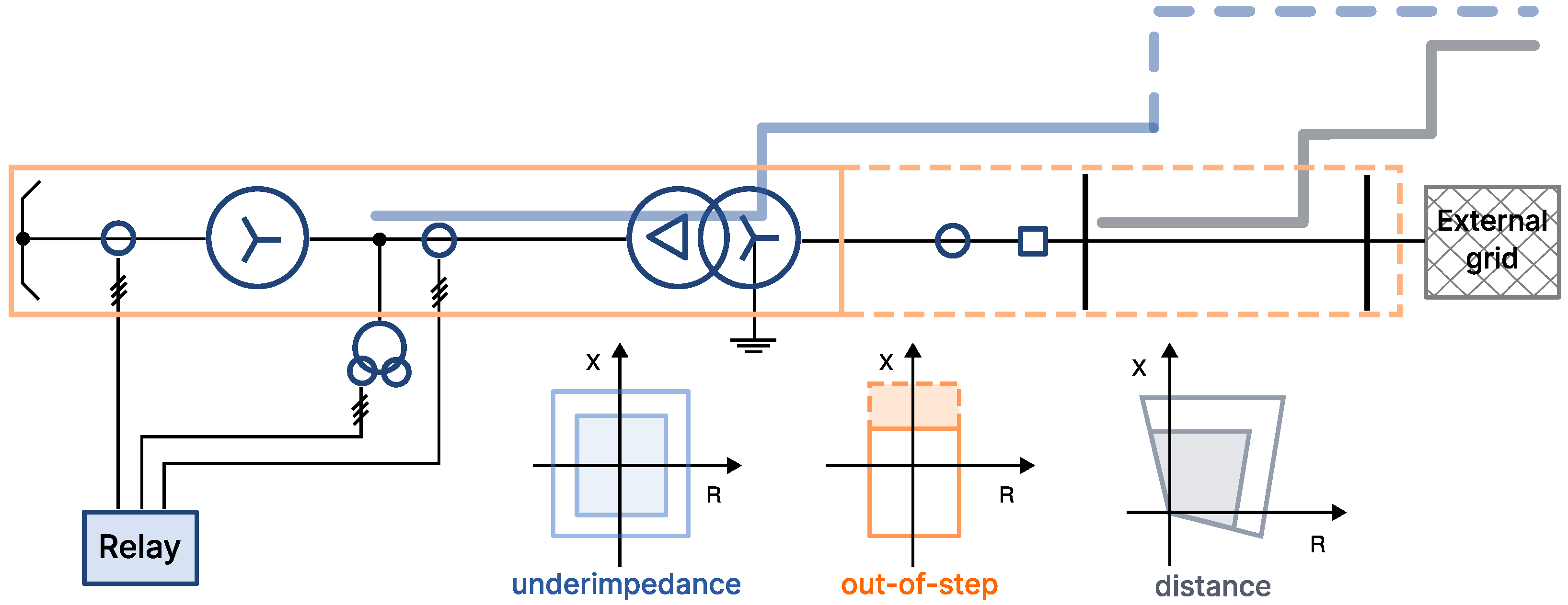
2]. The emphasis is on the correct operation, which presumes proper setting and coordination of different generator relay protection functions and absence of false activations. The foremost significant here are the underimpedance (21G) and the out-of-step (78) relay protections, where correct operation above all precludes spurious generator trips during (stable) power swings [3]. Accurate detection and correct distinction between stable and unstable power swings, by these relay protection functions, is seen as a critical precondition for valid generator tripping. With the reduced system inertia, this task becomes even more influential [4]. Consequently, the intention of this paper is to enhance these generator relay protections by supporting their traditional decision-making logic (where it exists) with a machine learning based classifier, in order to strengthen them against erroneous trips due to (stable) generator swings. If the power swing detection logic is absent from the relay protection function, then the classifier can supply it. The classifier will specifically aid and support relay decisions for blocking the underimpedance protection during stable swings. It will also expedite trip decisions of the out-of-step protection during unstable swings. It needs to be stated here that the implementation and configuration of these generator protections will be in accordance with the IEC standards and will be primarily seen from the European practice, which differs considerably from that found in the United States (US); see, e.g., Siemens 7UM62 [5] and ABB REG 670 [6] manuals for more information. This also means that both of these protections will feature polygonal trip characteristics (and not MHO-based circles used extensively in the US). Implementation will consider numerical protection relays from Siemens AG.
Generator underimpedance relay protection (also known as the impedance or distance protection, ANSI 21G) is intended for the protection of generator and its step-up transformer, along with everything in-between them (i.e., high-current bus duct connections and equipment), from damage due to short-circuit events. In its standard two-zone configuration, it protects (part of) the generator’s stator winding and both windings of the step-up transformer from phase-to-phase short-circuit faults [5]. It supplements a differential protection of the generator and its step-up transformer (ANSI 87T) and serves as its main backup protection. And, unlike differential protection, it can further serve as a backup protection for the incident transmission lines. However, since it has open-ended protection zones, it needs to be coordinated with the relay protection of transmission lines. The extent of the protection coverage (i.e., reach) for different zones (and different fault types), along with their backup protection scope, can vary considerably between different implementations. Furthermore, this protection is considered superior to the various generator overcurrent protection schemes (e.g., overcurrent with undervoltage seal-in) and preferred for large machines. However, it needs to be carefully guarded against spurious generator trips during stable swings, initiated by the faults within the power system [7]. This is where the proposed classifier comes into play, by strengthening reliability (and credibility) of the decisions made by the traditional underimpedance protection swing detection logic.
Generator out-of-step protection (also known as the pole-slip protection, ANSI 78) is intended not only for the protection of the generator from damage emanating from the pole slipping events, where it needs to timely disconnect the generator from the rest of the power system, but also for preventing instability from spreading to other portions of the system. Namely, the sudden and unexpected loss of generating capacity during a disturbance can precipitate major power system outage. In its standard two-zone configuration, out-of-step protection fully covers the generator, its step-up transformer and extends into the power system [5,6]. The extent of the out-of-step protection reach into the power system, and subsequent coverage of the incident transmission lines, depends primarily on the zone settings. This protection, first and foremost, needs to make consistently reliable and trustworthy decisions regarding unrecoverable (i.e., unstable) generator swings [5]. As such, this function can benefit from the support of the proposed classifier as well.
Machine learning (ML) has been applied for supporting and extending (and, in some cases, even completely replacing) various traditional protection functions [8,9]. A general review of the power system protection with the aid of ML techniques has been presented in [10]. More specifically, multidimensional relay protection, based on support vector machine, was proposed in [11]. Overcurrent relays were replaced by XGBoost classifiers in [12]. Li et al. in [13] recommended an ML based identification of the impedance trajectory for the generator out-of-step protection. Another approach to the adaptive generator out-of-step protection, this incorporating the phasor measurement units (PMU), was suggested in [14]. Furthermore, detecting the loss of excitation condition of synchronous generators has been tackled by applying ML methods as well, e.g., [15,16,17]. Detection of islanding by means of the ML was proposed by Meera et al. in [18]. Also, ML has been applied in connection with the distance protection of high-voltage transmission lines (TL), e.g., [19,20], including the use of artificial neural networks [21]. However, very few papers deal with the ML support of the generator underimpedance relay protection.
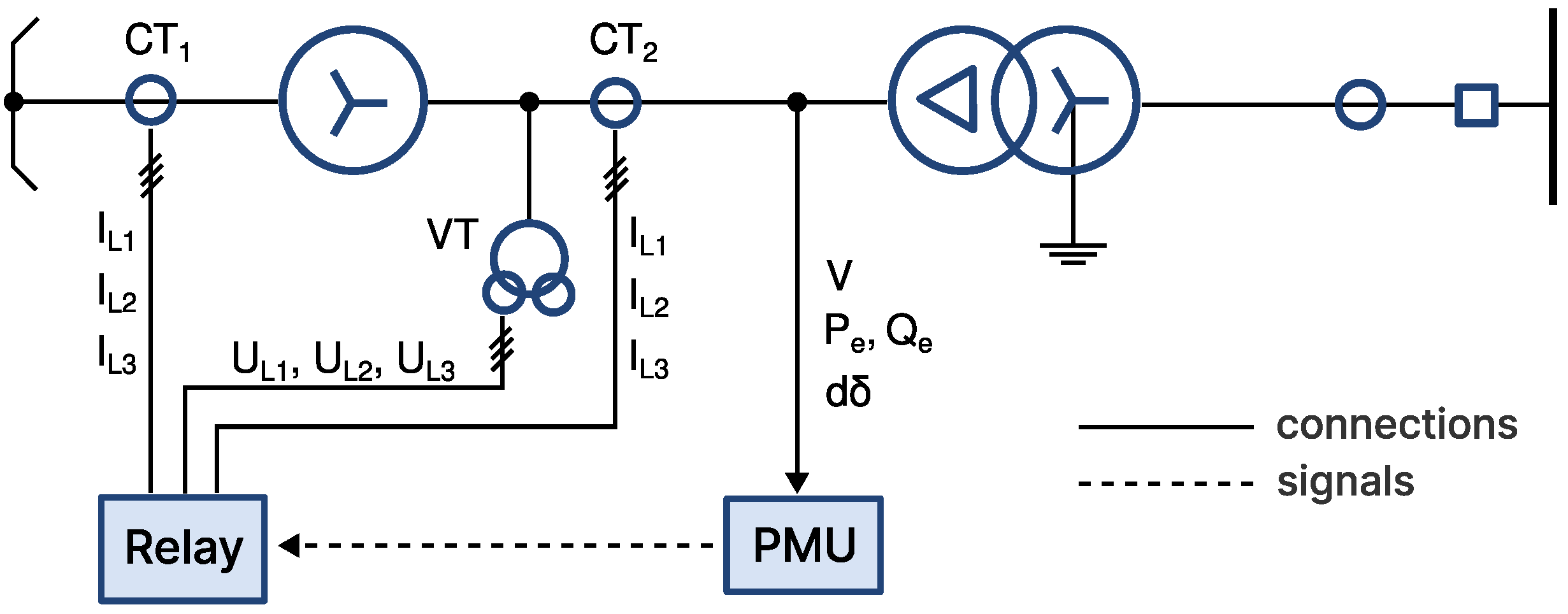
This paper will introduce a support vector machine (SVM) classifier for detecting generator swings (from the generator transient stability assessment). It will be trained and tested on the IEEE New England 10-generator benchmark power system. It will use PMU-type signals taken from the generator terminals and will be interfaced with the generator relay protection logic. It will reinforce relay decisions regarding blocking of the underimpedance protection during stable generator swings. Likewise, it will also enhance the out-of-step relay protection, by allowing faster generator tripping for unrecoverable swings. Numerical relays that do not possess power swing detection logic (such as the REG 670 from ABB) can be retrofitted with this classifier. We believe that the proposed approach presents a novel contribution to the state-of-art of generator relay protection.
The paper is organized in the following manner. Section 2, first briefly introduces these two impedance-based generator protection functions, then describes the classifier building process and its interfacing with the generator protection. Application of the classifier in the IEEE New England 10-generator power system is provided in Section 3, which is followed by conclusion in Section 4.

2. Generator Relay Protection

A brief introduction to the generator’s underimpedance and out-of-step relay protection, as seen from the European practice, will be provided here, since we will not be dealing with MHO-type relays (that are extensively used in the US). For those interested in the US practice, however, there is an excellent book [3]. Next, SVM classifier will be introduced and its interface with the generator protection functions will be explained.

2.1. Underimpedance Protection Function

We consider that the underimpedance protection is connected to the current transformers (CT) in the generator neutral point and voltage transformers (VT) at the generator terminals. This means that the faults in the generator’s stator winding will be detected in the third quadrant of the R–X complex plane, while those on the power system will be detected in the first quadrant; see, e.g., Siemens 7UM62 relay manual for additional information [5]. It is important to note that this is different from the way impedance is seen from the self-polarized MHO relay at the generator, [3]. Moreover, the protection characteristic is polygonal and can be either a square (Siemens 7UM6x) or a rectangle (Siemens 7UM8x), centered around the origin of the R–X complex plane.
We will also consider that the underimpedance protection will provide backup for the incident transmission lines and can have up to three independent protection zones (Siemens 7UM85), [22]. The first zone will cover part of the generator impedance (in the third quadrant) and will reach up to 70% of the step-up transformer impedance in the first quadrant. The second zone will cover the rest of the step-up transformer impedance and must overreach the high-voltage (HV) bus. The third zone, when used, will cover the (longest) incident TL [22]. Obviously, second (and third) zones must be coordinated with the relay protections of TLs. Relay connection, along with the extent of different protection zones, is graphically illustrated in Figure 1. Out-of-step protection, with its polygonal two-zone characteristic, is superimposed on the figure as well.
Generator underimpedance zone settings calculation is based on the following general rules (reactances in primary Ohm values) [5,22]:
  • Zone Z1:
    Z 1 = 70 % · Z t r
  • Zone Z2:
    Z 2 = 100 % · Z t r
  • Zone Z3:
    Z 3 = max 0.9 · ( Z t r + 1 R t r 2 · Z 1 L ) ; Z t r
where: Z t r and R t r are, respectively, impedance and the transformation ratio of the step-up transformer, while Z 1 L is the (direct) impedance of the incident transmission line.
We will also further consider that the step-up transformer has a vector group YNd5 (which is typical for the European practice) and introduces a 150-degree rotation. It is well known that the fault impedance measured by the underimpedance protection is influenced by the vector rotation and that the relay will have a wrong measurement for certain fault types on the HV side of the step-up transformer [3]. For this particular vector group YNd5, underimpedance protection will have an overreach (i.e., the fault location is seen as being farther away than it actually is) for single-phase short circuits at the HV side of the step-up transformer; see Siemens 7UM85 relay manual [22] for more information.
Finally, we consider that the generator underimpedance protection has an internal power swing detection logic. In case of the 7UM62 relay, it is based on the speed measurement of the impedance vector ( Δ Z / Δ t ) as it enters the protection characteristic [5]. In case of the 7UM85, it is more sophisticated and measures trajectory monotony, continuity and uniformity [22]. It may be interesting to note that the underimpedance protection of the REG 670 from ABB does not have any internal power swing detection logic [6]; see also [23] for an in-depth analysis. Power swing blocking of the generator underimpedance protection may be imposed by transmission system operator (TSO) requirements. Even if it is not strictly required by regulations, it is extremely important to mitigate possible erroneous generator trips due to stable power swings, which can have significant (negative) repercussions on the overall stability of the power system.

2.2. Out-of-Step Protection Function

We consider that the generator out-of-step protection is based on the two-zone polygonal impedance characteristic (see Figure 1) [5]. It is connected to the CT and VT at the generator’s terminals. Typically, its first zone covers the generator (in the third quadrant) and up to 90% of the step-up transformer (in the first quadrant). Second zone will cover the (longest) incident TL and, depending on the network strength, may extend further into the power system [5,6].
Generator out-of-step zone settings calculation is based on the following general rules (reactances in primary Ohm values) [5,22]:
  • Zone 1:
    Z b c = X g + 90 % · Z t r
  • Zone 2:
    Z c d = 10 % · Z t r + Z 1 L
where X g is the transient reactance of the generator. Extent of the polygon in the R–direction (for the swing angle of δ = 120 ) is calculated from [5]:
Z a = Z b c + Z c d 2 · tan ( δ / 2 )
The maximum detectable swing frequency can now be estimated using the following approximate formula (where T = 20 ms for a 50 Hz system), [5]:
f m a x = 4 π · 1 T · Z a Z b c + Z c d
However, detailed adaptation of the out-of-step protection characteristic to the particular generator, in terms of the critical swing angle, is very difficult. Namely, swing impedance trajectory is influenced by many factors, including governor action, mechanical damping of nearby units, shunt loads, shunt capacitance effects, generator saliency, type of excitation, manual or automatic voltage regulation, etc. According to [3], the best way to determine the critical swing angle is to model the power system using a transient stability analysis software. The system representation must include loads, generators, their voltage regulators and governor controls in a large area surrounding the machine in question. The system would then be tested by applying faults at critical points (using maximum anticipated clearing times). These faults would be applied at various load levels and generation mix to determine the most severe survivable swing for the unit in question. The impedance trajectories generated from these test cases would then be used to set and fine-tune the out-of-step relay protection [3].
Out-of-step protection trips the generator in the second zone only after three to four power swings; see, e.g., 7UM62 relay manual [5] for manufacturer suggested settings. The protection function features a counter, which increases with each detected power swing (that can also be reset to zero). If the counter reaches a preset number of swings, the relay trips the generator. Each pole slip is associated with a strong stator current pulse, which causes severe torque transients in the turbine generator shaft. The fatigue life of the shaft can be used-up after a few pole slip events [3]. Depending on the electrical center of the swing, these stator currents approach levels of three-phase short circuit current for a fault at generator terminals (which is the maximum current the machine is designed to withstand). On a strong power system, electrical center of the swing trajectory will move into the generator, thus exacerbating the situation and raising the importance of the out-of-step protection. Finally, it needs to be mentioned here that the generator tripping due to pole slip events also imposes significant stress on the circuit breaker, in terms of the transient recovery voltage (TRV). Namely, opening a breaker across an out-of-phase network exposes the breaker to the maximum TRV of 4.0 p.u. voltage across the contacts, which is double that normally encountered [3].

2.3. Power Swing Classification with a Support Vector Machine

Classification of power swings (as seen from the generator terminals), emanating from short-circuit events within the network, is tackled by means of the SVM binary classifier. It uses a radial basis function (RBF) kernel and distinguishes between stable and unstable generator swings from the PMU signals measured at the generator terminals. Figure 2 depicts connection of the relay and a PMU to the generator. The PMU collects phase voltage (V), active ( P e ) and reactive ( Q e ) power and rotor angle deviation ( d δ ), as time-domain signals.
Features are then created from these signals for training the classifier. Two time stamps are extracted from each of the time-domain signals, first at the pickup time and second at the trip time of the second zone of the incident TL distance protection. A short-circuit in the first zone of the distance protection will be tripped 0.1 s after the pickup time and that in the second zone will be tripped 0.4 s after the pickup time; see [24] for additional information regarding distance protection (ANSI 21) of TLs. This means that the classifier is trained using only eight features (two per each signal). It should be mentioned that there is no communication between the distance protection of TLs and generator relay functions.
Training and test sets are then created using the stratified shuffle split strategy, so that 80% of data is used for training and remaining 20% for testing. Stratified shuffling preserves class imbalance while randomly distributing instances. The last data preparation step considers standardization of features (i.e., centering and scaling to unit variance). Figure 3 graphically represents training and test phases of the model building process. The SVM classifier has two hyperparameters that need to be fine-tuned during training. These are the classifier’s regularization (C) and the RBF kernel coefficient ( γ ). Classifier regularization (as a squared 2 penalty) trades off misclassification of training examples against simplicity of the decision surface [25]. Kernel coefficient defines how much influence a single training example has on the overall decision boundary. Both hyperparameters are initially drawn from exponential distributions: C E x p ( λ = 0.01 ) , γ E x p ( λ = 0.1 ) and optimized using a random search (for 200 iterations) with a three-fold cross validation on the training data set. Class weight balancing is used during training, where class weights are adjusted inversely proportional to class frequencies in the input data.
Furthermore, due to the class imbalance, a so-called Matthews correlation coefficient 1 , + 1 is used for scoring models during training [25]:
M C C = T P · T N F P · F N ( T P + F P ) · ( T P + F N ) · ( T N + F P ) · ( T N + F N )
where: TP is the number of true positives, TN the number of true negatives, FP the number of false positives and FN the number of false negatives. These values can be obtained from the confusion matrix. An MCC value close to + 1 indicates a high performing classifier. Now, binary predictions are obtained from the following expression:
y ^ ( x ) = sign β + i SV α i · e γ · x x 2 ,
where summation is performed over the space of support vectors (SV) using α i weights, while β is the intercept.
Model performance is tested using a separate test set (not seen during training) and model score is reported from a three-fold cross validation (Figure 3). Furthermore, false positive (FP) results (type I errors) and false negative (FN) results (type II errors) will not have equal importance for both protection functions. Consequently, it is important for the classifier’s performance to fine-tune its decision probability threshold by further comparing and contrasting the precision and recall metrics [25]. Since the positive class here represents unstable swing events, false negative results are more of a concern for the out-of-step protection. Hence, the classifier decision probability threshold will be different between underimpedance and the out-of-step protection functions, and each will have its own individual setting. However, there will be only one SVM classifier, serving both protection functions.
Generator relay settings calculation, as mentioned, ordinarily involves carrying out numerical simulations of different short-circuit events, which are also part of the machine’s transient stability study. All data generated during these simulations should be used for (offline) training of the SVM classifier. This will ensure that the classifier is fine-tuned to the particular swing trajectories of the generator at hand.

2.3.1. SVM Supporting Underimpedance Protection

Interfacing SVM classifier with the generator underimpedance protection is proposed on the bases of 7UM62 numerical relay [5]. Figure 4 depicts a schematic connection of the SVM classifier’s decision binary input to the internal power swing detection logic of the underimpedance protection. Provided connection is intended for blocking of the second zone (“Zone Z2”) during stable power swings. Firstly, after the pickup has been activated, relay calculates the impedance (as seen from the relay position) by selecting an appropriate measurement loop. This means that, due to the YNd5 vector group of the step-up transformer, a two-phase short circuit at the HV transformer terminals will be seen as a three-phase short circuit at the generator side (with unequal fault-current distribution in the three phases). Also, in this case, only a single phase-to-ground loop (that with the largest fault current) will have a correct measurement. However, a single-phase short circuit at the HV transformer terminals will not only be seen as a two-phase short circuit at the generator side (necessitating correct loop selection), but will also have an inevitable measuring error which cannot be corrected [22]. Setting of the zone extent and time grading is carried out by means of the “Zone Z2” and “Zone T2” parameters [5].
Power swing detection logic of the 7UM62 relay, in particular, is based on measuring the speed of an impedance vector trajectory during its crossing between two polygonal characteristics [5]. This logic is here reinforced by introducing another external binary signal from the SVM classifier (Figure 4), which means that the underimpedance protection is blocked only during stable swings (and not during all swings). A stable swing is determined by combining decisions from the traditional relay power swing detection logic (based on a polygonal characteristic and impedance trajectory) with that of the SVM classifier (which distinguishes between stable and unstable power swings based on PMU measurements). This increases the decision’s validity, because of its need to satisfy conditions imposed by two independent sources. In addition, parameter “SVM Thr. Z<” enables user to set the classifier’s decision probability threshold level in order to minimize type I errors.
It needs to be emphasized that the traditional power swing detection logic of the 7UM62 cannot by itself distinguish between stable and unstable power swings; it can only recognize that there is a swing and not a short-circuit event within its (second) protection zone [5]. Hence, an introduction of the SVM classifier brings in new information to the relay and enables clearly identifying any power swing as stable or unstable. In addition, output of this protection function now includes an additional independent signal (“Stable Swing”), which authenticates the stable power swing by combining the trajectory information with the classifier output. This makes it more reliable than the traditional “Power Swing” output (that relies on trajectory information only). Furthermore, user can activate and deactivate (by means of the new parameter “Blk.Z2Swing”) SVM classifier’s support to the traditional power swing detection logic (see Figure 4). Hence, the SVM classifier may be inactive during the relay commissioning phase, providing only the “Stable Swing” signal which can be compared to the existing “Power Swing” output.

2.3.2. SVM Supporting Out-of-Step Protection

Interfacing SVM classifier with the generator out-of-step protection is again proposed on the bases of 7UM62 numerical relay [5]. Figure 5 depicts a schematic connection of the SVM classifier’s decision binary input to the out-of-step protection. It is here intended as a support for a faster generator tripping during unstable swings in the second protection zone (“Zone Z2”) only.
When the out-of-step protection function determines that there is a power swing (i.e., impedance trajectory is crossing through the second zone of its polygonal characteristic), the associated counter will be incremented ( n 1 ), [5]. Parameter “T-Holding” is used for resetting this counter. At the same time, if the SVM classifier decides that this is an unstable generator swing (from which there can be no recovery), there is no need to continue exposing the generator to mechanical stresses associated with subsequent swings (i.e., additional two or three swings) as defined by the parameter “Rep.Char.2”), [5]. In this way, by incorporating decision from the SVM classifier, out-of-step protection can trip the generator in the second zone after a single swing (instead of a total of three or four), which would considerably decrease the mechanical stresses of the machine (especially if the swing locus is close to the generator). Furthermore, any trip decision arising from the SVM decision support activates independent output signal “Trip char. 2” (see Figure 5). During relay commissioning phase, signal “Trip char. 2” can be used as an indicator only (and compared with the “O/S Trip char. 2” output for reference). In this way the commissioning period may be utilized for final fine-tuning of the classifier with actual measurements. Parameter “SVM Thr. O/S” enables the user to set the classifier decision probability threshold level in order to minimize type II errors. Finally, protection function provides an additional “Unstable swing” signal which can be used as a general zone-independent indication of an unstable power swing event.

3. IEEE New England 10-Generator Power System Example

A well-known IEEE New England 10-generator power system is taken as a basis for classifier training and testing. This power system features ten synchronous machines, in addition to transmission lines, three-phase transformers and loads [26]. One of the generators serves as a surrogate of the external power system. Each machine includes an excitation system control, automatic voltage regulator, power system stabilizer and turbine governor control. Loads are represented as simple R-L-C branches. Transmission lines are modeled as three-phase Π –section blocks. A complete electro–mechanical transient simulation of the power system is carried out for different load levels and three different short-circuit types scattered throughout the network; see [27] for additional information. A total of 9360 time-domain simulations were performed, which created the dataset.
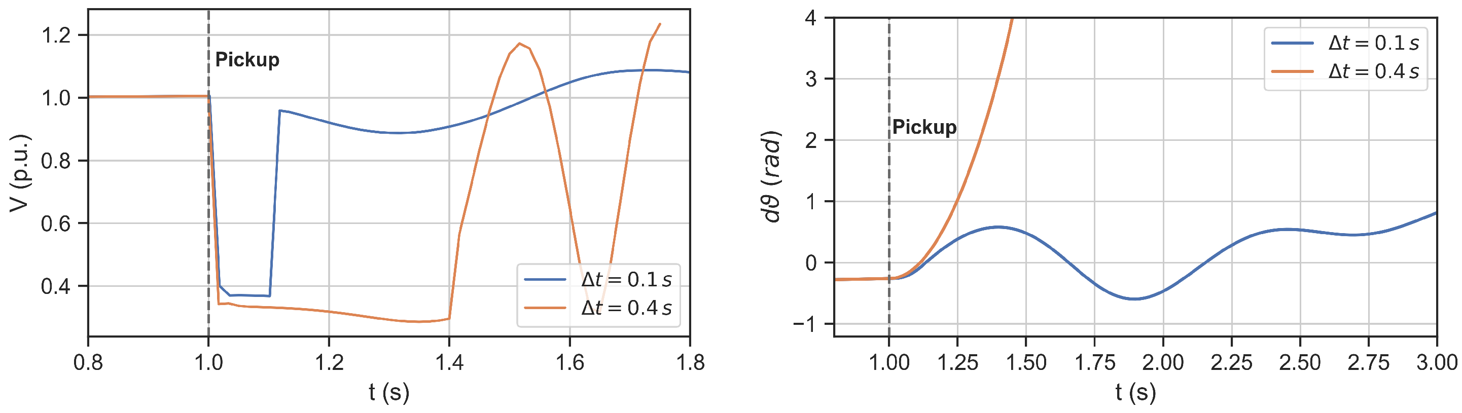
As an example of the simulation output, two time-domain signals of the generator voltage and rotor angle deviations are presented in Figure 6, which demonstrate strong influence of the incident TL distance relay trip time on the transient stability of the generator. Distinction between stable and unstable generator swing is clearly visible from the rotor angle deviation. In addition, 
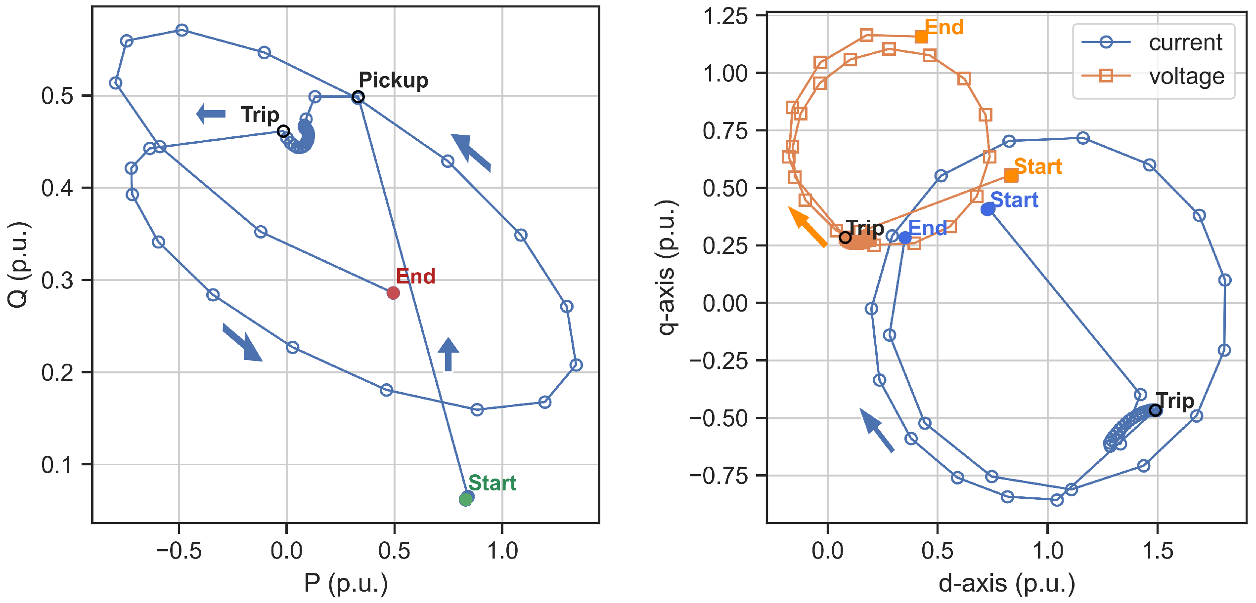
Figure 7 graphically presents a trajectory of the unstable generator swing, following a single-phase short circuit on the incident TL. A trajectory in the P–Q plane can be readily transformed into the R–X plane while retaining its circular shape.
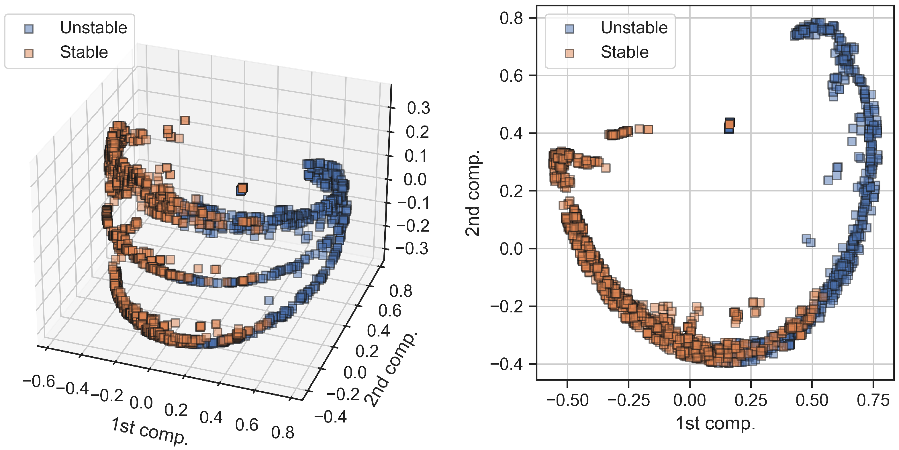
Features, extracted from the dataset of time-domain systematic simulations (see Section 2.3), can be visually depicted using the process of low-dimensional embedding. We show the results of this process here by using the kernel principal component analysis (kPCA) while projecting the original features space into the three-dimensional embedding [25]. Consequently, 
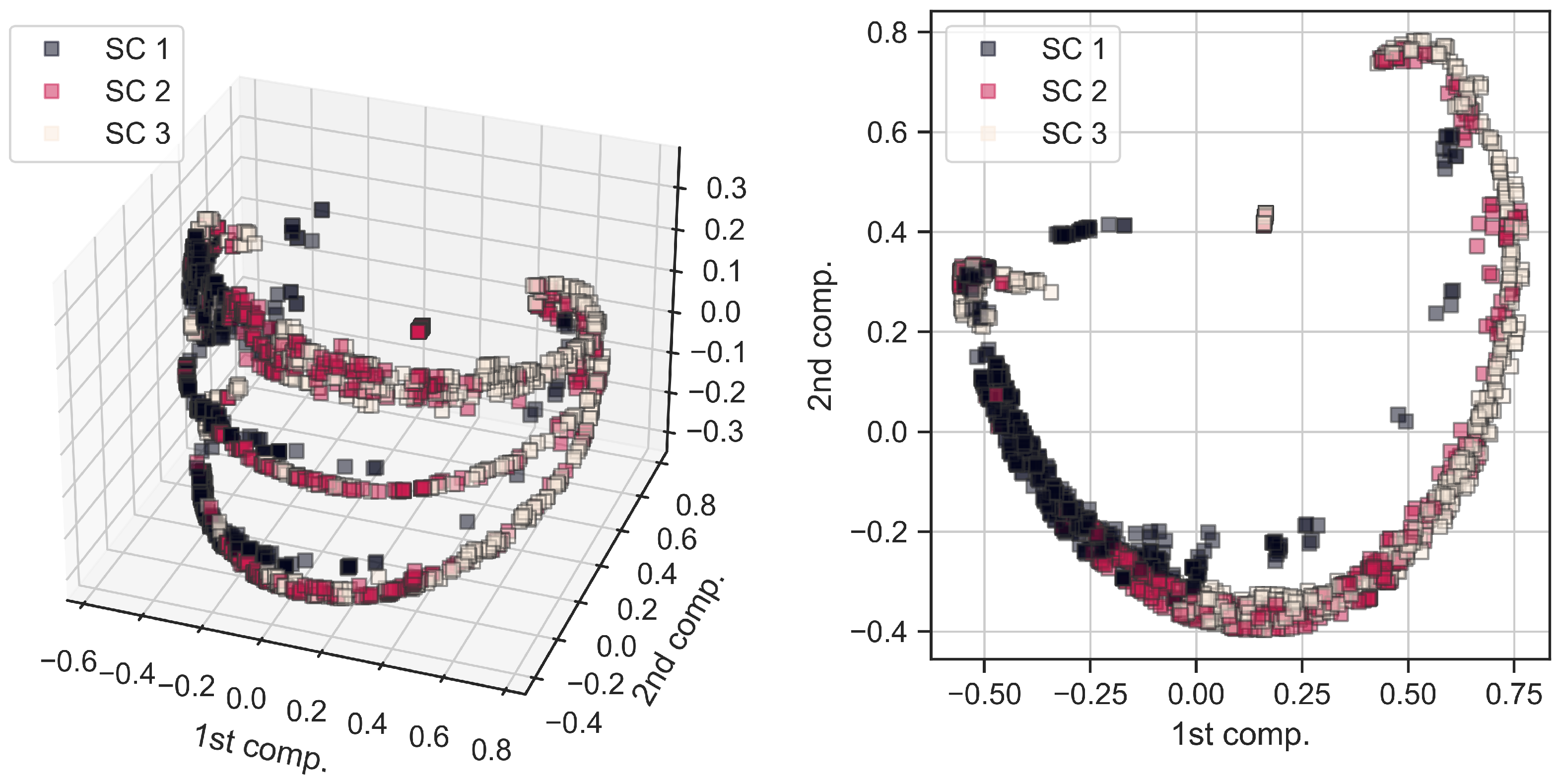
Figure 8 graphically depicts different short-circuit events (from all parts of the network) in 3D (left side) and 2D (right side) coordinate systems of principal components. Furthermore, SVM classifier predictions (i.e., stable and unstable generator swings), arising from these events, are also graphically depicted using the same kPCA embedding and displayed in Figure 9. By comparing Figure 8 and Figure 9, it can be clearly seen that the main source of unstable generator swings are the three-phase (SC 3) short circuit events. At the same time, single-phase (SC 1) short circuit events are far less prone to cause generator’s loss of stability. This is completely expected.
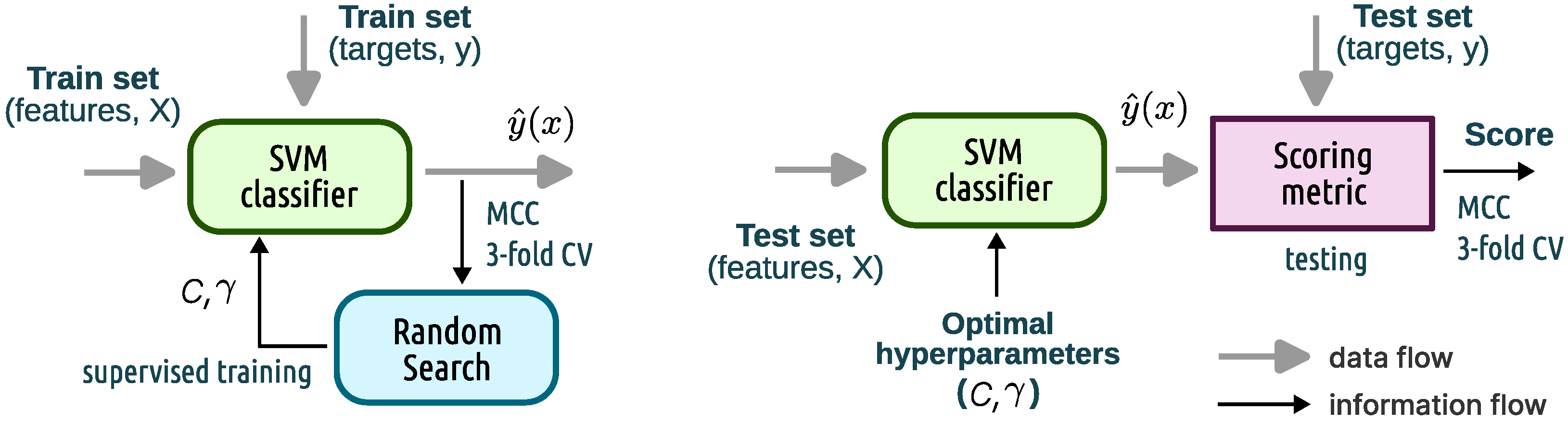
The classifier’s performance is gauged by means of the scores obtained from the test set. For example, the Matthews correlation coefficient of the classifier, using the 3–fold cross validation on the test set, yields: 0.957 ± 0.028 . In addition, classifier’s performance can be further examined by contrasting its precision and recall metrics [25]. Precision is defined as a ratio between a number of true positives and a number of predicted positive results. Recall is defined as a ratio between a number of true positives and an actual number of positive cases. Classifier will balance these two opposing metrics. Table 1 presents classifier’s individual precision and recall measures obtained from the test set. Although these values can vary between different runs, due to randomness involved in data shuffling and model training (i.e., random search for optimal hyperparameters), it can be seen from the presented results that the proposed SVM classifier obtained high scores across several important metrics. We were also able to consistently reproduce this level of performance between runs.
Additionally, in order to examine the influence of the dataset size on the classifier’s performance, we used only 1000 (stratified) random samples from the original dataset (again 80% for training and 20% for testing), which constitutes only cca. 10% of the original data. Training the classifier with only 800 samples yields a Matthews correlation coefficient of 0.914 ± 0.037 (from the 3–fold cross validation on the test set of 200 samples). It also yields an area under the receiver operating characteristic (ROC) curve of 0.982 ± 0.006 . Table 2 presents more complete results obtained by using this small dataset. It can be seen that, even with only cca. 10% of the original dataset, the classifier was still able to achieve very good performance with relatively high scores. This is a reassuring finding, which means that a dataset can be purposefully built each time, as part of the relay settings calculations, using simulation results from the (extended) machine stability studies.
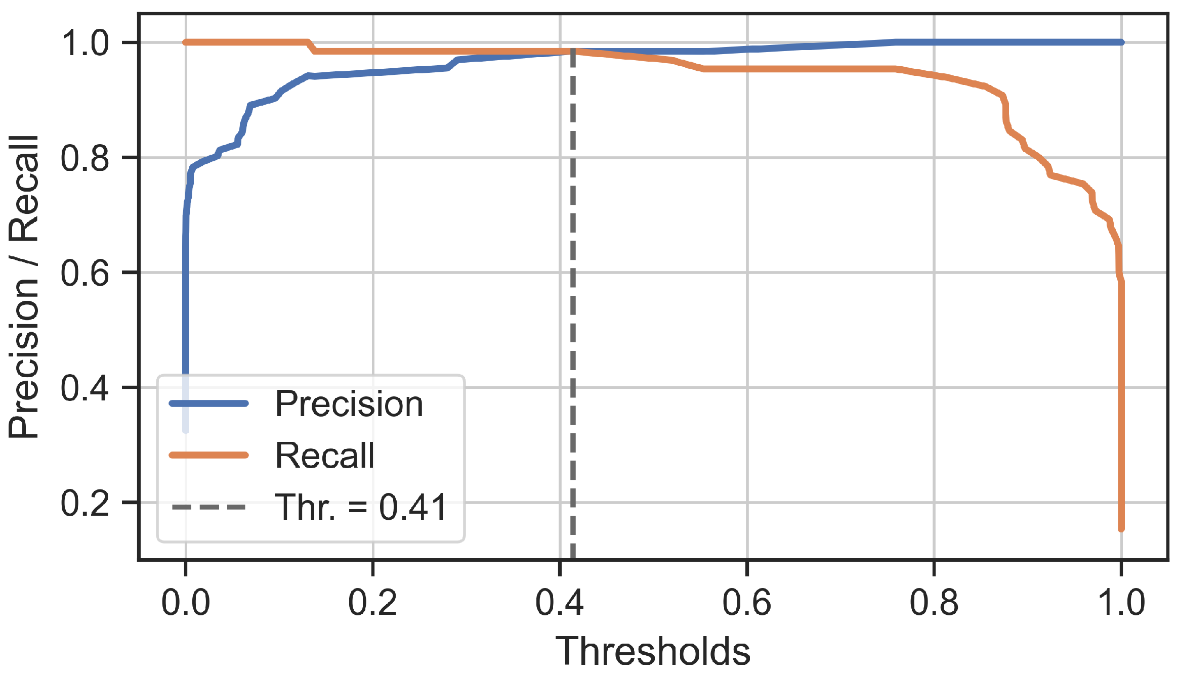
Fine-tuning of the classifier’s decision probability threshold, as a final step in the training process, can be carried-out using the precision–recall curves [25]. For that purpose, 
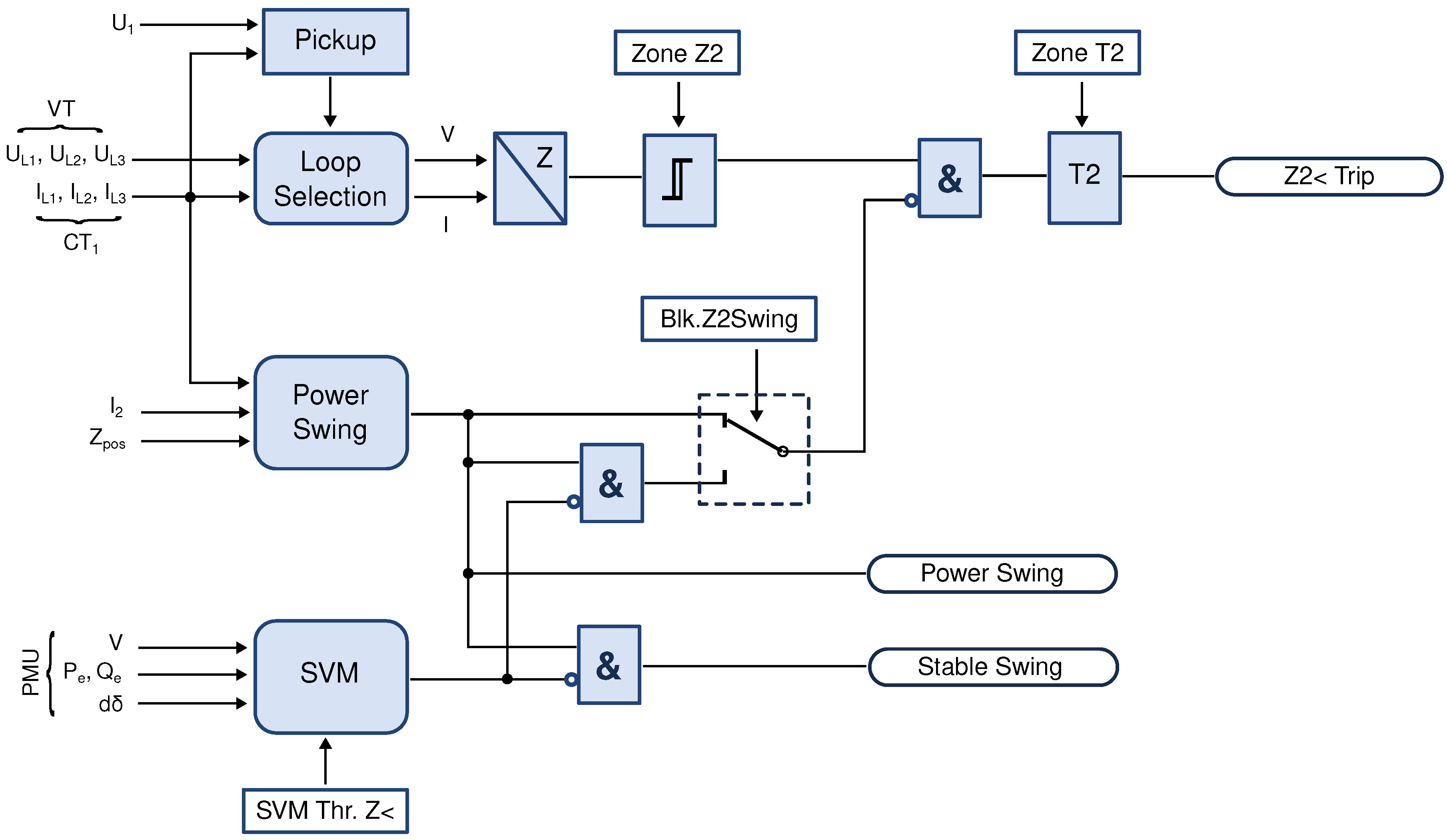
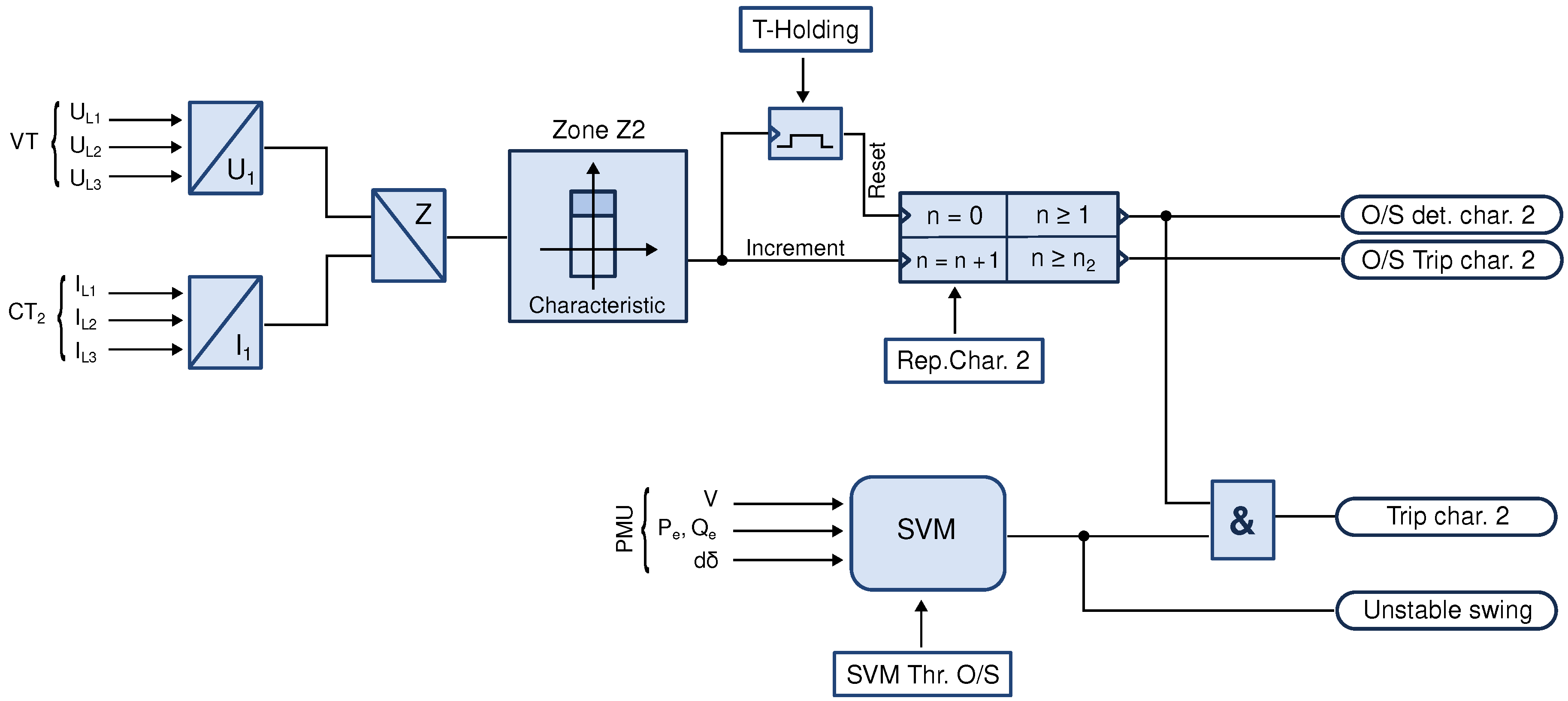
Figure 10 presents precision and recall curves, obtained from predictions on the test set of 200 samples, as a function of the decision probability thresholds. It can be seen that as the precision is increased, recall will inevitably decrease, and vice versa. It is desirable for the SVM threshold supporting underimpedance protection to have higher recall (lower type II errors), while that of the out-of-step protection to have higher precision (lower type I errors). These different thresholds—for the same SVM classifier—can be independently determined from the precision–recall curves (where threshold is related to the selectable parameters “SVM Thr. Z<” and “SVM Thr. O/S” from Figure 4 and Figure 5, respectively). Selected probability threshold level, at the same time, defines the classifier’s confidence score regarding the class predictions. For example, setting the probability threshold level at 0.8 , in relation to the out-of-step protection, means that the classifier will be reporting unstable power swing cases with an 80% confidence. Unstable power swings that turn out to be associated with a confidence that is lower than the 80% would not be influencing out-of-step relay decisions. This ensures that only very confident predictions can interact with the traditional relay protection logic.
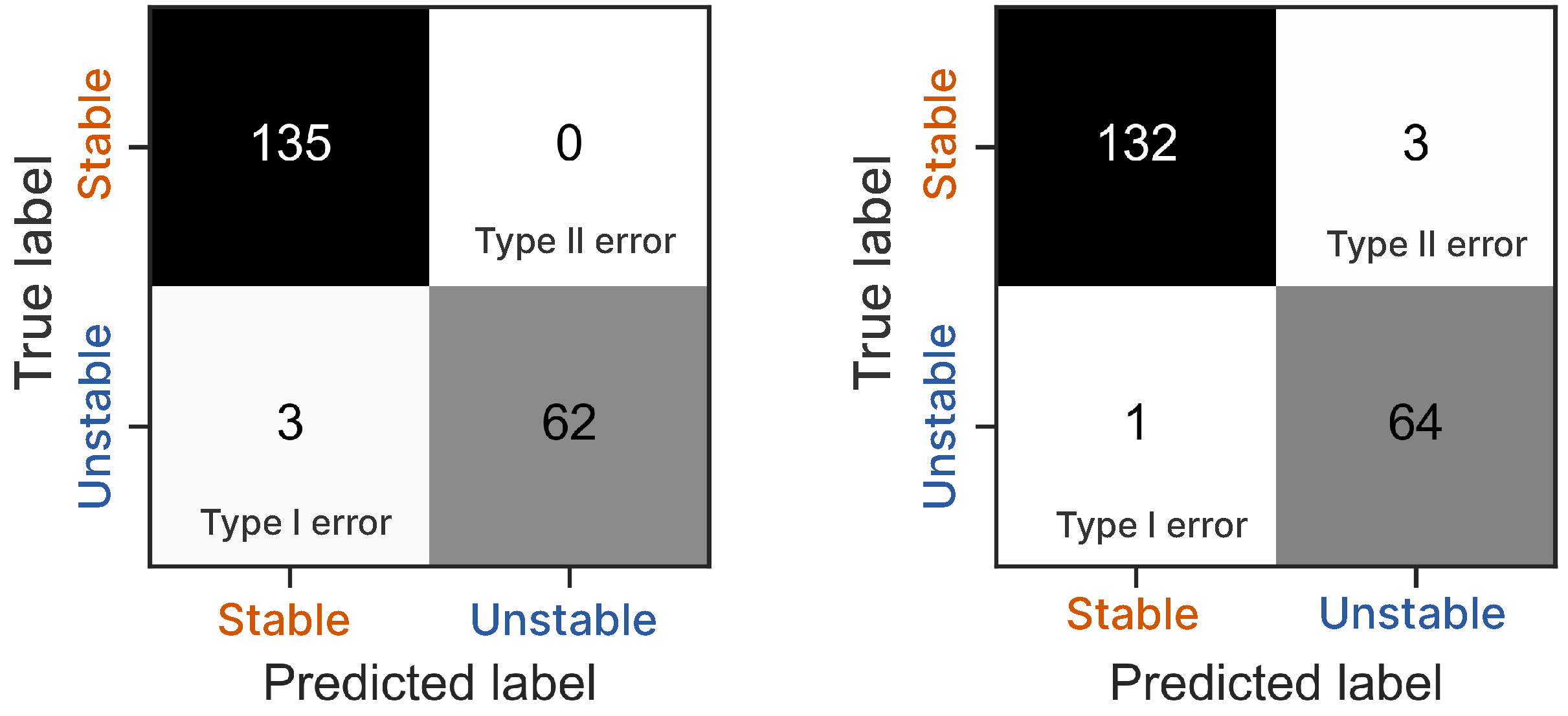
Influence of the decision threshold value on the type I and II errors is further presented graphically, by means of the confusion matrices in Figure 11, again for this test set of 200 samples. If the threshold is selected at the intersection of precision and recall curves, the number of type I and type II errors would be exactly the same. Confusion matrix, at the same time, enables deriving several other useful metrics, such as: Youden’s J–statistic, Jaccard’s index, F–measures ( F β , F 1 ), Fowlkes–Mallows index, and others. These can be employed as a means of further examining the classifier’s performance. For example, the Jaccard’s score on the test set of 200 samples (using 3–fold cross validation) yields: 0.889 ± 0.045 .
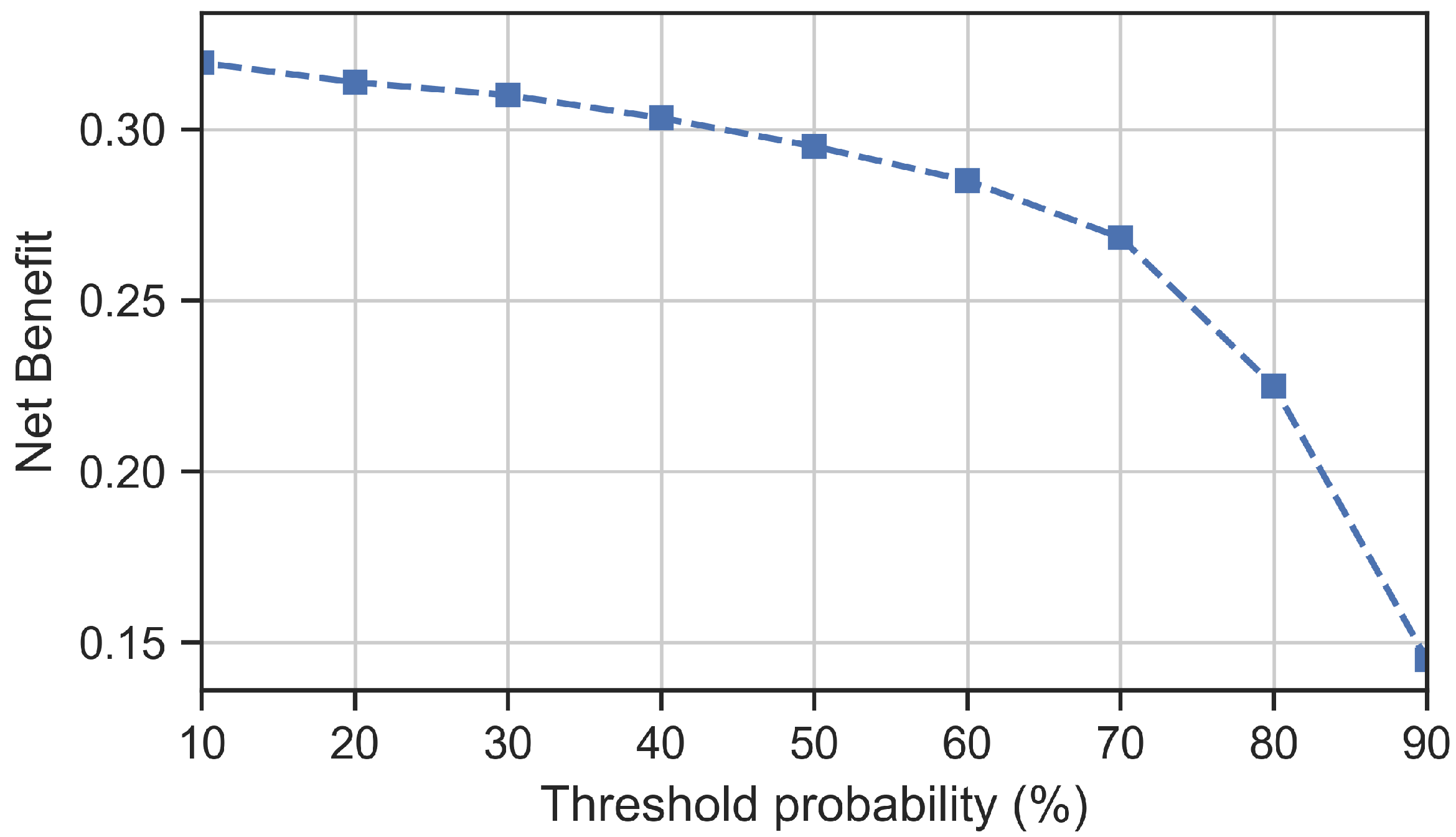
In addition, a confusion matrix forms a basis for the so-called “net benefit” analysis, which weighs the relative harms (i.e., costs) of false-positive and false-negative predictions across different threshold probabilities; see [28] for more information. The net benefit of the presented SVM model, for any probability threshold level t [ 0 , 1 ] , can be calculated from the following relation:
B t = 1 N · T P F P · t 1 t
with N being the total number of samples. A net benefit can acquire values from the minus infinity up to the value that is equal to the incidence of the positive class. A model provides utility only when its net benefit value is greater than zero. If the net benefit is calculated for different (ascending) threshold values, the resulting curve (that relates the net benefit values with associated thresholds) is known as a decision curve. It can be used to assess model’s usefulness, to select the appropriate probability threshold level and to compare different models [28]. Figure 12 presents a decision curve for the SVM classifier at hand, obtained from the small dataset of 1000 samples. It can be seen that the net benefit of the model is positive.
Finally, it should be stated that the SVM classifier was trained on a synthetic data generated by numerical simulations. Considering the importance of the power system, further testing of the classifier is recommended, preferably using the actual (measured) generator data. This, however, could be difficult to achieve, since the participation (and permission) of the machine owner would be required.

4. Conclusions

The massive integration of power electronic converters, along with the continuous displacement of synchronous generators, is fundamentally changing the dynamic characteristics of power systems, which imposes new challenges on the stable and resilient operation of power grids. Since the generator relay protections are directly facing these challenges, strengthening their decision-making logic may be seen as a prudent step in the direction of securing the system stability. Hence, this paper introduced a support vector machine based (binary) classifier for supporting the synchronous generator underimpedance (21G) and out-of-step (78) relay protection functions, which are based on the IEC standards and European practice. Both protection functions are impedance-based and feature polygonal characteristics (i.e., they do not employ MHO-type circles, which is a standard practice in the US). As a side note, it could be mentioned that Siemens’ implementation of the underexcitation protection (i.e., loss-of-field protection, ANSI 40) does not feature MHO-type offset circle either (which is again very different from the US practice); instead, it is based on a special three-lines characteristic, presented in the admittance (G, B) plane and applied directly on top of the generator’s capability curve.
The proposed classifier was trained on the dataset of PMU-type signals obtained from time-domain numerical simulations of the IEEE New England 10-generator test power system, following a standard practice used in many research papers. It is then proposed as a support for the internal relay logic, for blocking of the underimpedance protection during stable power swings. It is also intended as a support for faster generator tripping, by the out-of-step protection, during unstable generator swings. In both cases, it is meant to reinforce second zone (i.e., overreaching) of both underimpedance and out-of-step protection functions, since these are “looking” into the network. In case that the underimpedance protection features a third zone, it could be used with it as well. Furthermore, in case that the underimpedance relay protection function does not provide internal power swing detection logic (as is the case with, e.g., REG 670 from ABB), the classifier could be used as an independent source of external swing detection (binary) signal for blocking the protection during stable swings.
It ought to be mentioned that it is important to train the classifier using transient simulation data obtained directly from the machine stability studies, which are often performed as part of the protection relay settings calculation. This data set does not have to be very large, as shown previously, since the SVM classifier is easy to train (i.e., it has only two hyperparameters). This will also ensure that the classifier is familiar with particular swing trajectories of the machine at hand. As part of this training process, the classifier can also be fine-tuned by selecting decision probability threshold levels that are appropriate for minimizing prediction errors.
Finally, considering the importance of generator protections for the power system stability—particularly in these evolving circumstances emanating from the large-scale integration of renewable energy sources—further testing of the classifier is recommended. Hence, future work envisions, among others, increasing the class imbalance with new network contingencies and introducing different types of (artificial) noise and measurement errors into the dataset for testing the classifier robustness and performance under these adverse conditions. Also, testing the classifier with changing generation mix and reduced system inertia is seen as another important future research direction.

Author Contributions

Conceptualization, P.S.; methodology, P.S.; software, P.S.; validation, P.S. and D.L.; investigation, D.L.; resources, P.S. and D.L.; data curation, D.L.; writing—original draft preparation, P.S.; writing—review and editing, D.L.; visualization, P.S. All authors have read and agreed to the published version of the manuscript.

Funding

This research received no external funding.

Data Availability Statement

The dataset is made available under the CC-BY license and deposited on Zenodo with a https://doi.org/10.5281/zenodo.4521886, accessed on 1 March 2024.

Acknowledgments

The authors kindly acknowledge the contribution of our colleague A. Kunac for carrying out extensive numerical simulations that created the original dataset.

Conflicts of Interest

The authors declare no conflicts of interest.

Abbreviations

The following abbreviations are used in this manuscript:
ANSIAmerican national standards institute
ANSI 21transmission line distance protection
ANSI 21Ggenerator (under)impedance protection
ANSI 78generator loss of synchronism (i.e., out-of-step) protection
ANSI 40generator underexcitation (i.e., loss-of-field) protection
ANSI 87Tdifferential protection of generator and its step-up transformer
IEEEInstitute of electrical and electronics engineers
IECInternational electrotechnical commission
CTcurrent transformer
VTvoltage transformer
TLtransmission line
MLmachine learning
HVhigh voltage
TPnumber of true positives
TNnumber of true negatives
FPnumber of false positives
FNnumber of false negatives
MCCMathews correlation coefficient
PMUphasor measurement unit
SVMsupport vector machine
RBFradial basis function
ROCreceiver operating characteristic
TRVtransient recovery voltage
TSOtransmission system operator

References

  1. Wachter, J.; Gröll, L.; Hagenmeyer, V. Survey of Real-World Grid Incidents-Opportunities, Arising Challenges and Lessons Learned for the Future Converter Dominated Power System. IEEE Open J. Power Electron. 2024, 5, 50–69. [Google Scholar] [CrossRef]
  2. Mackey, M.J. (Ed.) Optimisation of Protection Performance during System Disturbance, Brochure No. 232; Technical Report, CIGRE WG B5.09; CIGRE: Paris, France, 2003. [Google Scholar]
  3. Reimert, D. Protective Relaying for Power Generation Systems; CRC Press: Boca Raton, FL, USA, 2006. [Google Scholar]
  4. NERC. Reliability Guideline: Performance, Modeling, and Simulations of BPS-Connected Battery Energy Storage Systems and Hybrid Power Plants; Technical Report; North American Electric Reliability Corporation: Atlanta, GA, USA, 2021. [Google Scholar]
  5. Siemens. SIPROTEC 4 Multifunctional Machine Protection 7UM62; Manual V4.7, C53000-G1176-C149-5; Siemens AG: Munich, Germany, 2018. [Google Scholar]
  6. ABB. Generator Ptrotection REG670; Relion 670 Series, 1MRK502027-UEN; ABB: Zürich, Switzerland, 2011. [Google Scholar]
  7. Benmouyal, G.; Hou, D.; Tziouvaras, D. Zero-Setting Power-Swing Blocking Protection; Selinc: Pullman, WA, USA, 2012; pp. 1–29. [Google Scholar]
  8. Kulikov, A.; Loskutov, A.; Bezdushniy, D. Relay Protection and Automation Algorithms of Electrical Networks Based on Simulation and Machine Learning Methods. Energies 2022, 15, 6525. [Google Scholar] [CrossRef]
  9. Loskutov, A.; Pelevin, P.; Vukolov, V. Improving the recognition of operating modes in intelligent electrical networks based on machine learning methods. E3S Web Conf. 2020, 216, 01034. [Google Scholar] [CrossRef]
  10. Aminifar, F.; Abedini, M.; Amraee, T.; Jafarian, P.; Samimi, M.H.; Shahidehpour, M. A review of power system protection and asset management with machine learning techniques. Energy Syst. 2022, 13, 855–892. [Google Scholar] [CrossRef]
  11. Kulikov, A.L.; Bezdushniy, D.I.; Sharygin, M.V.; Osokin, V.Y. The support vector machine application in the implementation of multidimensional relay protection. E3S Web Conf. 2019, 139, 01040. [Google Scholar] [CrossRef]
  12. Banihashemi, F.; Cuzner, R.M. Novel XGBoost Classifier Based Relaying Approach with 2 Classes of Protection Zone. In Proceedings of the 2023 IEEE Energy Conversion Congress and Exposition (ECCE), Nashville, TN, USA, 29 October 2023–2 November 2023; pp. 951–956. [Google Scholar] [CrossRef]
  13. Li, Z.; Hu, C.; Cui, D.; Wang, Y.; Zhu, Y. Out-of-Step Protection in Generator Based on Intelligent Identification of Impedance Trajectory. In Proceedings of the 2022 International Conference on Artificial Intelligence and Computer Information Technology (AICIT), Yichang, China, 16–18 September 2022; pp. 1–4. [Google Scholar] [CrossRef]
  14. Desai, J.P.; Makwana, V.H. Phasor Measurement Unit Incorporated Adaptive Out-of-step Protection of Synchronous Generator. J. Mod. Power Syst. Clean Energy 2021, 9, 1032–1042. [Google Scholar] [CrossRef]
  15. Ramadoss, H.; Muthiah, G. Machine learning approach to differentiate excitation failure in synchronous generators from power swing. Electr. Eng. 2023, 105, 2041–2054. [Google Scholar] [CrossRef]
  16. Ramadoss, H.; Muthiah, G. Ensemble machine learning approach to identify excitation failure in synchronous generators. Eng. Fail. Anal. 2023, 152, 107506. [Google Scholar] [CrossRef]
  17. Rahmkhoda, E.; Faiz, J.; Abedini, M. Detecting loss of excitation condition of synchronous generator in the presence of unified power flow controller based on data mining method. Electr. Power Syst. Res. 2024, 228. [Google Scholar] [CrossRef]
  18. Meera, A.; Vinod, V.; Rajeev, T.; Joseph, A. Design, Development and Testing of a Support Vector Machine based Relay for Islanding Detection. In Proceedings of the 2022 IEEE Global Conference on Computing, Power and Communication Technologies (GlobConPT), New Delhi, India, 23–25 September 2022; pp. 1–6. [Google Scholar] [CrossRef]
  19. Kharusi, K.A.; Haffar, A.E.; Mesbah, M. Adaptive Machine-Learning-Based Transmission Line Fault Detection and Classification Connected to Inverter-Based Generators. Energies 2023, 16, 5775. [Google Scholar] [CrossRef]
  20. Uddin, M.N.; Rezaei, N.; Arifin, M.S. Hybrid Machine Learning-Based Intelligent Distance Protection and Control Schemes With Fault and Zonal Classification Capabilities for Grid-Connected Wind Farms. IEEE Trans. Ind. Appl. 2023, 59, 7328–7340. [Google Scholar] [CrossRef]
  21. George, N.; Surajnath, P.; Naidu, O.; Yalla, P. Machine Learning Based Setting-free Reach Element For Zone-1 Distance Protection. In Proceedings of the 2019 8th International Conference on Power Systems (ICPS), Jaipur, India, 20–22 December 2019; pp. 1–5. [Google Scholar] [CrossRef]
  22. Siemens. SIPROTEC 5 Generator Protection 7UM85; Manual V8.83 and Higher, C53000-G5040-C027-A; Siemens AG: Munich, Germany, 2021. [Google Scholar]
  23. Lizer, M. Power unit impedance and distance protection functions during faults in the external power grid. Acta Energetica 2012, 4, 22–41. [Google Scholar]
  24. Ziegler, G. Numerical Distance Protection: Principles and Application; Siemens AG: Munich, Germany, 1999. [Google Scholar]
  25. Murphy, K.P. Machine Learning: A Probabilistic Perspective, 4th ed.; MIT Press: Cambridge, MA, USA, 2013. [Google Scholar]
  26. Moeini, A.; Kamwa, I.; Brunelle, P.; Sybille, G. Open data IEEE test systems implemented in SimPowerSystems for education and research in power grid dynamics and control. In Proceedings of the 2015 50th International Universities Power Engineering Conference, Stoke on Trent, UK, 1–4 September 2015; pp. 3–8. [Google Scholar] [CrossRef]
  27. Sarajcev, P.; Kunac, A.; Petrovic, G.; Despalatovic, M. Power system transient stability assessment using stacked autoencoder and voting ensemble. Energies 2021, 14, 3148. [Google Scholar] [CrossRef]
  28. Vickers, A.; Elkin, E. Decision curve analysis: A novel method for evaluating prediction models. Med. Decis. Making 2006, 26, 565–574. [Google Scholar] [CrossRef] [PubMed]
Figure 1. Relay connection, extent of underimpedance protection zones (blue), their coordination with distance protection of the incident TL (gray), along with their respective polygonal protection characteristics. Out-of-step protection zones and characteristic (orange) are superimposed as well.
Energies 17 01820 g001
Figure 2. Connection of the PMU and its interface with the generator relay protection.
Energies 17 01820 g002
Figure 3. Process of supervised training (left) and subsequent testing (right) of the SVM classifier.
Energies 17 01820 g003
Figure 4. Proposed SVM connection to the underimpedance protection, in support of the internal power swing detection logic which is blocking the second zone during stable generator swings. Scheme is based on the 7UM62 relay from Siemens [5].
Energies 17 01820 g004
Figure 5. Proposed SVM connection to the out-of-step protection for faster generator tripping in the second zone. Scheme is based on the 7UM62 relay from Siemens [5].
Energies 17 01820 g005
Figure 6. Example of generator voltage (left) and rotor angle deviation (right), during single-phase short-circuits on the incident TL that were cleared in the first (0.1 s) and second (0.4 s) distance protection zones.
Energies 17 01820 g006
Figure 7. Example of trajectories for an unstable generator swing during single-phase short circuit on the incident TL. Left side shows trajectory of generator power (in the P–Q coordinate system). Right side shows trajectory of stator current and voltage (in the d–q coordinate system). Pickup and trip times of the associated distance protection are indicated for reference ( Δ t = 0.4 s).
Energies 17 01820 g007
Figure 8. Different short-circuit events seen in the 3D (left) and 2D (right) coordinate systems of principal components (produced from the kPCA embedding); single-phase (SC 1), double-phase (SC 2) and three-phase (SC 3) faults.
Energies 17 01820 g008
Figure 9. Different short-circuit events seen in the 3D (left) and 2D (right) coordinate systems of principal components (produced from the kPCA embedding) in terms of generator stable or unstable swings.
Energies 17 01820 g009
Figure 10. Precision and recall of the SVM classifier as a function of the decision probability threshold value. A particular threshold value at the intersection of the precision and recall curves is marked for reference. Classifier was trained using 800 and tested on 200 random samples from the original dataset.
Energies 17 01820 g010
Figure 11. Classifier’s confusion matrices obtained from the small test set of 200 samples with two different decision probability threshold levels: Thr . = 0.6 (left) and Thr . = 0.2 (right).
Energies 17 01820 g011
Figure 12. Decision curve based on the net benefit analysis for the SVM classifier trained on the small dataset.
Energies 17 01820 g012
Table 1. Classifier’s precision and recall for stable and unstable cases, obtained from the test set.
Swing CasePrecisionRecallF1–ScoreSupport
Stable0.9980.9880.9931267
Unstable0.9760.9950.985605
Table 2. Classifier’s precision and recall for stable and unstable cases, obtained using the subset of 1000 samples (i.e., from the test set of 200 samples).
Swing CasePrecisionRecallF1–ScoreSupport
Stable0.9850.9480.966135
Unstable0.9010.9690.93365
Disclaimer/Publisher’s Note: The statements, opinions and data contained in all publications are solely those of the individual author(s) and contributor(s) and not of MDPI and/or the editor(s). MDPI and/or the editor(s) disclaim responsibility for any injury to people or property resulting from any ideas, methods, instructions or products referred to in the content.

