Article

Performance Analysis of Wave Rotor Combustor Integration into Baseline Engines: A Comparative Study of Pressure-Gain and Work Cycles

1
College of Energy and Power Engineering, Nanjing University of Aeronautics and Astronautics, Nanjing 210016, China
2
School of Aeronautics and Mechanical Engineering, Changzhou Institute of Technology, Changzhou 213032, China
*
Authors to whom correspondence should be addressed.
Energies 2024, 17(9), 2074; https://doi.org/10.3390/en17092074
Submission received: 1 March 2024 / Revised: 16 April 2024 / Accepted: 18 April 2024 / Published: 26 April 2024
(This article belongs to the Special Issue Novel Method, Optimization and Applications of Thermodynamic Cycles)

Abstract

:
This study presents two concepts for integrating a wave rotor combustor (WRC) into a baseline engine: the wave rotor pressure-gain cycle (WRPGC) and the wave rotor work cycle (WRWC). Performance parameters were calculated under different thermodynamic cycles, and a comparative analysis of the thermodynamic cycles was conducted, considering both the ideal- and actual-loss conditions. Furthermore, the impact of the WRC precompression ratio, turbine inlet temperature, and fixed peak cycle temperature on the thermodynamic-cycle performance was investigated. The results indicate that embedding a WRC into a baseline engine with a compressor pressure ratio higher than 24.0 does not lead to an improvement in the thermal efficiency. However, under a baseline engine pressure ratio of 3.6, the actual-loss WRC cycle achieves efficiency improvements of 40.5% and 49.5% in the WRPGC and WRWC, respectively, compared to the baseline engine cycle. Increasing the wave rotor precompression ratio or the turbine inlet temperature ratio results in greater performance improvements for the WRWC compared to the WRPGC. When the peak cycle temperature of the wave rotor is fixed, there exists a narrow pressure ratio range wherein the WRPGC outperforms the WRWC. Therefore, the WRPGC is more suitable for embedment in baseline engines with lower pressure ratios.

1. Introduction

In the face of the surging energy demand, there is a growing interest in using engines based on efficient combustion. Currently, gas turbine engines remain the primary source of power and play a crucial role in aerospace propulsion systems [1,2,3]. However, modern gas turbine engines typically employ Brayton cycles or constant-pressure cycles, which convert the energy from combustion into the internal energy of the working fluid under constant-pressure conditions. This process significantly increases the entropy generation during combustion [4,5,6]. Furthermore, the inherent irreversibility of the heat gain in actual combustion processes leads to an unavoidable reduction in the total pressure by 3–5% during combustion [7,8]. The improvement in the efficiency of modern gas turbine engines is mostly achieved by increasing the compressor pressure ratio, the turbine inlet temperature, and the aerodynamic efficiency of the rotating components. Though considerable research and engineering efforts have been expended, significant progress in improving the thermal efficiency of gas turbine engines has not materialized [9,10,11].
By replacing the traditional thermodynamic cycle used in propulsion systems, significant improvements in the performance of gas turbine engines can be achieved. The Humphrey cycle, which is based on the Brayton cycle, replaces the constant-pressure combustion process with constant-volume combustion [12,13]. The primary benefit of the Humphrey cycle compared to the Brayton cycle lies in its volume-constrained heat release leading to a pressure increase. This mechanism transforms a part of the released chemical heat directly into mechanical rather than internal energy, thereby limiting entropy growth during combustion. Such a pressure boost enables Humphrey-cycle engines to outperform Brayton-cycle engines in power generation with identical heat inputs. Unlike the Otto cycle that also harnesses pressure-gain combustion, the Humphrey cycle ensures a complete expansion of the combustion gases, thereby allowing for an expansion ratio that is higher than the compression ratio. Hence, the Humphrey-cycle engine combines the advantages of gas turbine engines and intermittent engines [14].
The wave rotor combustor (WRC), as a typical device for implementing the Humphrey cycle, has unique precompression and expansion processes. By replacing the combustor of a gas turbine engine with the WRC, further improvements in the gas turbine performance can be achieved. Figure 1 depicts a visual representation of the WRC’s structure, with the wave rotor’s multiple channels strategically placed around its axis and contained within a rotating drum [15,16]. Encircled by two fixed end plates with ports, the drum’s rotation intermittently connects the channels with fluid flows, causing rapid compression and expansion inside them. The gas is compressed by shock waves and then ignited, and the constant-volume combustion can occur in the form of premixed turbulent combustion or detonation.
The WRC’s concept was first proposed in the 1950s [17] and regained research interest in the 1990s. Akbari and Nalim [18] provide a detailed explanation of the working principle of the WRC, as well as its history, advantages, and challenges. The U.S. DARPA Quiet Supersonic Platform (QSP) program aims to develop a quiet propulsion system by applying the WRC to a Mach 2.4 supersonic engine and conducting related performance calculations. The results show that replacing the traditional Brayton cycle with the WRC cycle can reduce the specific fuel consumption by 5–15% under supersonic cruise conditions [19]. Li et al. [20] and Nalim et al. [21] apply standard air thermodynamics and simplified aerodynamics to the performance analysis of a microturbine engine embedded with a WRC. With the combustor exit Mach number M3 as a variable, the simulation results indicate that embedding a WRC into the baseline engine can achieve a 24% increase in the specific work output and a 19% reduction in the specific fuel consumption when M3 is about 0.6. Antonios [22] applies the wave rotor to the gas turbines of high-speed naval vessels. By integrating a wave rotor to enhance the engine performance while keeping the basic components of the baseline engine unchanged, it is shown that embedding a wave rotor in a gas turbine with regeneration can achieve a 19% increase in the engine thermal efficiency.
Akbari et al. [23,24] introduces the concept of a two-stage radial-flow wave rotor and proposes the WRC as a power-output device. Performance parameters of the actual-loss cycles are calculated, and the results show that there are certain compressor pressure ratios wherein the cycle efficiency and network reach their peak. Sun et al. [25] derived the average expression for the thermal efficiency of the radial-flow WRC engine and compared the Humphrey cycle with the Otto, Diesel, and Brayton cycles. The results showed that, under the same initial conditions and peak cycle temperatures, the thermal efficiency of the Humphrey/Atkinson cycle is higher than those of the other cycles, especially at lower pressure ratios. Li and Gong et al. from Nanjing University of Aeronautics and Astronautics [26,27,28,29] conducted an overall performance analysis of the WRC applied to gas turbines, verifying the advantages of the WRC in improving the performance of the baseline engine. They further carried out numerical simulations on the unsteady flow and combustion characteristics of the WRC and established a simplified experimental system for the WRC. Successful combustion enhancement was achieved at wave rotor speeds below 2100 r/min.
Wave rotor engines include unsteady processes, and the thermodynamic cycles can be modeled through mass averaging. Daniel et al. [30] proposed a mass-averaging method for a pressure-gain combustor (PGC). They assessed the state of each mass unit as it left the combustor and integrated these to calculate the average cycle work extraction. The calculation was compared with that of the computational fluid dynamics (CFD) method, demonstrating that actual mass-averaged work extraction methods are highly practical and accurate for assessing the turbine performance in an unsteady flow. Sun et al. [25] developed a transient model for wave rotor engines that is not limited to the isentropic compression and expansion processes. The proposed efficiency expressions are consistent with steady isentropic processes, representing unsteady modeling results in an averaged form of steady modeling results. Daniel et al. [31] considered the inherent unsteadiness of PGC engines and analyzed the impact of the unsteadiness characteristics on the performance. The periodic conservation equations for mass, momentum, and energy were used in the unsteadiness analysis. The results indicate that unsteadiness analysis more accurately predicts the engine’s actual performance compared to traditional steadiness analysis. But the literature shows that the trend of the predictions is generally consistent, with smaller errors at higher flight Mach numbers.
Standard thermodynamic models can effectively predict the performance of wave rotor engines by accounting for the real losses. Jack et al. [32] used a simple thermodynamic model to determine the thermal efficiency and specific power of jet engines with integrated wave rotors. The actual isentropic relations for compression and expansion were employed. The performance calculations were compared with experimental results for General Electric’s four-port wave rotor. It was found that when the wave rotor’s compression and expansion efficiencies are 0.83, the precompression ratio is 1.8, the specific heat ratio is 1.3, and the calculated overall pressure ratio of the wave rotor closely matches the experimental results. Nalim et al. [21] established an aerothermodynamic model with variable specific heats. The compression and expansion processes were solved using isentropic relations that consider the losses, including internal-friction losses, shock losses, gradual-opening/-closing losses, and uneven-port-mixing losses. After comparing the calculation results with those of the CFD method, the performance indicators were found to be similar, indicating that the basic aerodynamic and thermodynamic models can reasonably predict the behavior of the actual system. This consistency may be due to the model’s appropriate handling of key physical processes and losses.
Significant research efforts have been undertaken worldwide to analyze the performance of the WRC. However, it is evident that these analyses predominantly consider the WRC either as a pressure-gain device or as a power-output device, without conducting a thorough comparative analysis between the two modes of operation with the baseline cycle. Furthermore, there is a notable absence of investigations regarding the optimal selection range of pressure ratios when integrating these two modes into the baseline engine. This study analyzes the structure and working principles of the WRC, and it establishes multiple thermodynamic-cycle models for wave rotor pressure-gain engines and wave rotor power-output engines. The investigation focuses on exploring the impacts of different thermodynamic cycles on the performance of the baseline engine. Furthermore, the study examines the variation patterns of the WRC thermodynamic performance parameters in relation to parameters such as the wave rotor precompression ratio and turbine inlet temperature. The primary emphasis is placed on analyzing the performance differences and application ranges between wave rotor pressure-gain engines and wave rotor power-output engines.

2. Wave Rotor Combustor

WRCs can be classified into the axial- and radial-flow types based on the direction of the flow in the channels. Both types can utilize curved channels, which are typical for generating torque. The operating principle is illustrated in Figure 2. The cycle begins with a precompression process wherein the exhaust port suddenly closes, causing the airflow at the port to decelerate and stagnate. This results in the propagation of a shock wave towards the inlet, compressing the fuel–air mixture within the channels. As the compression wave propagates to the intake port, the intake port closes. The precompression process helps to enhance the initial temperature and pressure before combustion, resulting in an increased peak combustion temperature and reduced entropy generation. Immediately after this, both ends of the channel are sealed. The fuel mixture inside the channel is ignited, leading to a constant-volume combustion process accompanied by shock-wave and flame interaction. After the combustion is completed, the exhaust port opens, resulting in a significant decrease in the gas pressure due to the pressure difference between the two ends, generating an expanding wave propagating towards the inlet. Finally, the intake port opens, allowing a mixture of fresh air and fuel to enter the channel, and the next cycle continues.
The WRC effectively utilizes the constant-volume combustion process and exploits the non-steady wave system induced by the timed closure and opening of the rotor channels to achieve further compression and expansion processes. Compared to axial-flow WRCs, the radial inlet and exhaust allow for a more compact arrangement, resulting in significant reductions in the engine length and weight. Additionally, centrifugal forces contribute to more thorough scavenging. The arrangement of the curved channels enables the generation of tangential momentum during the exhaust expansion process, leading to the production of torque. Thus, the WRC itself can output a certain amount of shaft work, while the power output from the combustion chamber can further enhance the thermal efficiency of the gas turbine engine [34]. The WRC exhibits a revolutionary and innovative nature in the context of future high-efficiency engines, calling for further exploration and research.

3. Establishment of Thermodynamic Cycle

Figure 3 shows the ideal P-V and T-S diagrams of the baseline Brayton cycle, Humphrey cycle, and wave rotor-embedded-in-the-baseline cycle. In the Brayton cycle, the process follows the sequence 1-2-3b-4. The Humphrey cycle modifies the Brayton cycle by replacing the constant-pressure heating process (2-3b) with a constant-volume heating process (2-3h). Compared to the Humphrey cycle, the wave rotor cycle introduces the wave rotor precompression process (2-A) and the wave rotor expansion process (B-3). Point 3 represents the state after the wave rotor expansion process. In ideal conditions and depending on the channel shape, it can be classified into two extreme cases. Point 3′ corresponds to the wave rotor pressure-gain cycle, wherein no shaft work is outputted by the rotor. The power generated by the rotor fully offsets the flow work and compression work, resulting in a pure-pressure-gain effect. Point 3″ corresponds to the wave rotor power-output cycle, wherein the rotor is able to generate the maximum shaft work. In this case, the rotor outlet expands completely to the rotor inlet state (P3″ = P2), achieving a pure-power-producing effect. When the turbine inlet temperature remains constant, point 3″ coincides with point 3b, indicating complete expansion to the turbine front pressure and temperature. The following modeling calculations will be performed for the baseline cycle as well as the two types of wave rotor cycles: the wave rotor pressure-gain cycle (WRPGC) and the wave rotor work cycle (WRWC).

3.1. Assumptions

Standard air thermodynamics is applied to each component of the WRC engine. The internal losses of the compressors and turbines are expressed by the adiabatic efficiencies. Similarly, the WRC’s internal losses are represented by the wave rotor adiabatic efficiencies, including the precompression and exhaust expansion processes. The effects of gradual-closure, leakage, and shock losses are classified to the adiabatic-efficiency definition. Consistent with general analysis methods, the heat released from combustion is considered an external heat addition, and the composition of the working gas is thought to be unchanged. Regardless of whether it is a wave rotor pressure-gain engine or a wave rotor work engine, the power to drive the compressor is thought to come solely from the turbine. Therefore, the wave rotor process does not participate in the power balance process, and the power it generates can be extracted separately for electricity generation or direct output. For the following engine cycle, it is assumed that the compressor inlet conditions are known. And for both the baseline engine and the wave rotor engine, the compressor inlet conditions are the same. The isentropic efficiencies of the compressors and turbines in both the wave rotor engine and the baseline engine are kept the same.

3.2. The Baseline Engine Cycle

The calculation process of the thermodynamic performance parameters for the baseline engine Brayton cycle is as follows. Assuming that the turbine inlet temperature ratio during the cycle is a constant value, the pressure ratio during the compression process is denoted as π c , the isentropic compression efficiency of the compressor is denoted as η c , and the isentropic expansion efficiency of the turbine is denoted as η e . First, the temperature ratios for each stage of the Brayton cycle are calculated. For each process in the Brayton cycle, we have the following:
The compression process:
T 2 T 1 = 1 + π c γ 1 γ 1 η c
The heating process:
T 3 T 1 = c o n s t
The expansion process:
T 4 T 1 = T 3 T 1 1 η t 1 π c 1 γ γ
The non-dimensional network:
w n e t c v T 1 = w T w C c v T 1 = c p T 3 T 4 c p T 2 T 1 c v T 1 = γ T 3 T 1 T 4 T 1 T 2 T 1 + 1
The thermal efficiency of the baseline cycle:
η t = 1 q 2 q 1 = 1 c p ( T 4 T 1 ) c p ( T 3 T 2 ) = 1 T 4 T 1 1 T 3 T 1 T 2 T 1
According to the principle that the total energy injected during the heating process is equal to the heat change, the fuel–air ratio can be calculated as follows:
Q = η b m f h u = m a + m f c p T 3 T 2
f = m f m a = c p T 3 T 2 η b h u c p T 3 T 2 = γ T 3 T 1 T 2 T 1 η b h u c v T 1 γ T 3 T 1 T 2 T 1
The specific fuel consumption (sfc) is defined as the amount of specific fuel consumed per unit of power produced over a specific period of time:
s f c = 3600 f w n e t

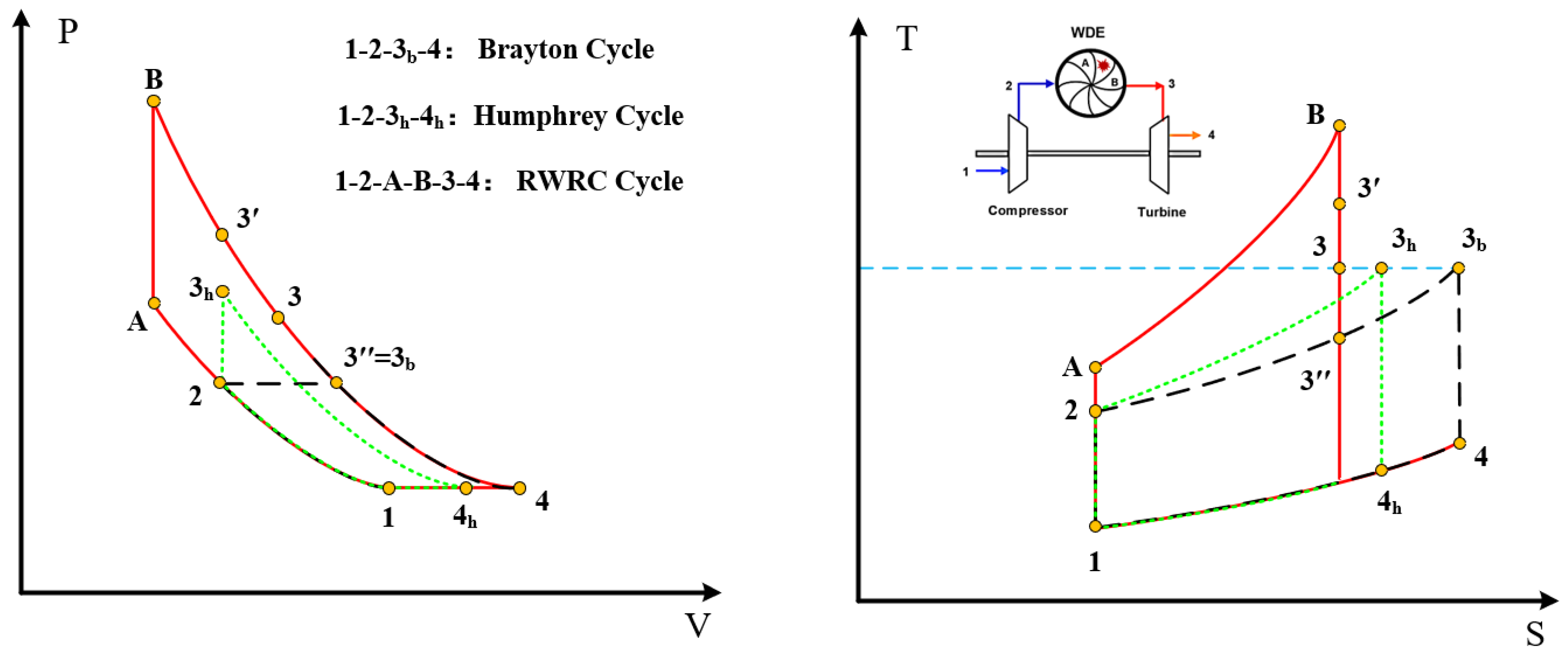
3.3. The Wave Rotor Pressure-Gain Cycle (WRPGC)

As a wave rotor in a pure-pressure-gain engine, the wave rotor neither outputs nor consumes any power. It solely functions as a pressure-boosting device. The pressurized gas, after being compressed by the wave rotor, further expands within the turbine to generate output power. To prevent the wave rotor from outputting power, the work generated by the wave rotor must fully offset its own flow work and compression work. The non-dimensional power generated by the wave rotor is as follows:
w r o t o r c v T 1 = c p T B T 3 c p T A T 2 R g T B T A c v T 1 = γ T 2 T 1 T 3 T 1 + T B T 1 T A T 1 = 0
The cycle parameters can be derived from the energy conservation principle applied to the steady-state operation of each component:
The compression process:
T 2 T 1 = 1 + π c γ 1 γ 1 η c
The wave rotor precompression process:
T A T 2 = 1 + π w c γ 1 γ 1 η w c
In this equation, π w c represents the pressure ratio of the wave rotor precompression, and η w c   represents the isentropic compression efficiency of the wave rotor precompression process.
The wave rotor constant-volume combustion process:
According to Equation (9), we can obtain the following:
T B T 1 = T A T 1 + γ T 3 T 1 T 2 T 1
P B P A = T B T A
The wave rotor expansion process: the total pressure ratio of the wave rotor expansion process can be derived from the isentropic relation between PB and P3, as follows:
P B P 3 = 1 1 1 T 3 T B η w e γ γ 1
where η w e represents the isentropic expansion efficiency of the wave rotor expansion process.
The turbine expansion process: the total pressure ratio during the turbine expansion process, P 3 / P 4 , is obtained by P B / P A :
P B P A = P 1 P 2 P 2 P A P B P 3 P 3 P 4 P 4 P 1 = 1 π c 1 π w c P B P 3 P 3 P 4
P 3 P 4 = P 3 P A π c π w c
The turbine exhaust temperature can be derived using the isentropic relation:
T 4 T 1 = T 3 T 1 1 η t 1 P 4 P 3 γ 1 γ
where η t is the isentropic expansion efficiency of the turbine process.
The non-dimensional network:
w n e t c v T 1 = w T w C + w r o t o r c v T 1 = c v T B T A c p T 4 T 1 c v T 1 = T B T 1 T A T 1 γ T 4 T 1 1
The thermal efficiency of the cycle is determined by the ratio of the network to the cycle’s total heat input:
η t = w n e t q i n = u B u A h 4 h 1 u B u A = 1 γ T 4 T 1 1 T B T 1 T A T 1
Based on the fact that the total energy input in the heating process is equal to the heat change plus the work output of the wave rotor, the specific fuel consumption can be calculated as follows:
Q = η Q m f h L H V = m a + m f c p T 3 T 2 + W r o t o r
f = m f m a = c p ( T 3 T 2 ) + w r o t o r η Q h L H V c p ( T 3 T 2 ) w r o t o r
s f c = 3600 f w n e t

3.4. The Wave Rotor Work Cycle (WRWC)

As a pure-power-producing wave rotor, the wave rotor operates solely as a power-output device without any pressure gain. In this mode, the wave rotor generates the maximum power, extracting the maximum amount of work from the fully expanded gas within the rotor channels. Thus, P 3 = P 2 , as shown by the position corresponding to point 3″ in Figure 3.
The temperature ratio in the constant-volume combustion process is equal to the pressure ratio:
T B T A = P B P A = P B P 3 P 3 P 2 P 2 P A = P B P 3 P 2 P A
where P B / P 3 is solved using the isentropic expansion relationship:
P 3 P B = 1 1 T 3 T B η w e γ γ 1
Substituting Equation (23), we have
T B T A = 1 1 T 3 T B η w e γ γ 1 1 π w c
P B P A = T B T A
Similarly, for other processes in the WRWC, all the performance parameters can be calculated.

4. Results and Discussions

For the thermodynamic calculations, a small turboshaft engine is selected to replace its combustor with a wave rotor combustor. The baseline engine has a compressor pressure ratio of 3.6. The compressor inlet temperature is 288.15 K, and the compressor isentropic efficiency is 0.805. The turbine inlet temperature is 1120 K, and the turbine isentropic expansion efficiency is 0.85. The precompression ratio of the wave rotor is 1.2. Both the compression and expansion efficiencies of the wave rotor are assumed to be 0.9. The combustion efficiency is 0.97 with a heating value of 42,900 kJ/kg. The specific heat capacity of the air, denoted as c p , is defined as follows [35]: c p = C 0 + C 1 θ + C 2 θ 2 + C 3 θ 3 , where θ = T K / 1000 , C 0 = 1.05 , C 1 = 0.365 , C 2 = 0.85 , and C 3 = 0.39 .

4.1. Comparative Study of Different Thermodynamic Cycles

At the same turbine inlet temperature, Figure 4 illustrates the relationship between the thermal efficiency of the actual-loss cycle considering losses and the ideal cycle as a function of the compressor pressure ratio. It can be seen that, under ideal conditions, the thermal efficiency increases with an increasing compressor pressure ratio. The WRC cycle has a higher efficiency than the Brayton cycle, and the ideal WRWC has a higher efficiency than the ideal WRPGC. Unlike the ideal cycles, actual-loss thermal cycles have lower thermal efficiency, and with the increasing pressure ratio, the actual-loss thermal efficiency initially increases and then decreases. There exists an optimal pressure ratio for the compressor, which maximizes the thermal efficiency. As the pressure ratio increases, the thermal efficiency of the WRC cycle decreases at a faster rate. When the pressure ratio exceeds 24.0, the thermal efficiency of the WRC cycle starts to become lower than that of the Brayton cycle. At the same time, the efficiency of the WRWC also becomes lower than that of the WRPGC. This indicates that the WRC embedded in the baseline engine with a pressure ratio higher than 24.0 does not exhibit performance advantages in terms of the thermal performance. Under the condition of a baseline engine pressure ratio of 3.6, the actual-loss WRC cycle yields performance improvements of 40.5% and 49.5% in the WRPGC and WRWC, respectively, relative to the baseline cycle.
Figure 5 and Figure 6 illustrate the variation in the thermal efficiency and specific fuel consumption with the specific work output. It is evident that, compared to the ideal cycle, the efficiency-specific work profile of the actual-loss cycle shifts towards the lower left corner, indicating a decrease in both the thermal efficiency and specific work. In contrast, the specific fuel consumption–specific work profile moves towards the upper left corner, corresponding to a decrease in the specific work and an increase in the specific fuel consumption. The WRC cycle has a higher specific work and a lower specific fuel consumption than the baseline engine. Each point in the figure corresponds to a specific compressor pressure ratio. It can be observed that, at the maximum specific work output, neither the thermal efficiency nor the specific fuel consumption reaches its maximum or minimum value. Similar to the baseline engine, the WRC cycle exhibits a similar trend wherein the lowest optimal compressor pressure ratio corresponds to the maximum output power, followed by the specific fuel consumption. The highest thermal efficiency is achieved at the maximum optimal compressor pressure ratio.
Figure 7 illustrates the performance enhancement of the WRPGC and WRWC compared to the baseline engine under different compressor pressure ratios in the actual-loss cycle. It can be observed that, for the WRPGC, the thermal efficiency and net output power increase by the same amount compared to the baseline engine. This is because the wave rotor does not directly contribute to the power output. Under the same heat input, the thermal efficiency and output power exhibit a similar increasing trend. From the figure, it can be seen that, at lower pressure ratios, there is a significant improvement in various performance parameters. For example, at a pressure ratio of 2.0, the thermal efficiency and specific work output can be increased by more than double, while the specific fuel consumption can be reduced by more than half. However, as the pressure ratio increases, the magnitude of improvement gradually decreases. The WRWC achieves a larger improvement in output power compared to the WRPGC, while the improvement in the thermal efficiency and specific fuel consumption is not significant. The zero-gain line relative to the baseline engine is marked in the figure. It can be observed that the specific fuel consumption, as a performance parameter, reaches the zero-gain line first, at pressure ratios around 10.0 (corresponding to the WRPGC) and 12.0 (corresponding to the WRWC). In contrast, the thermal efficiency and specific work output reach the zero-gain line at a pressure ratio of approximately 24.0. However, by this point, the specific fuel consumption has already increased by about 30.5% compared to the baseline engine. Therefore, when embedding the WRC into the baseline engine, it is advisable to choose a compressor pressure ratio lower than 10.0.

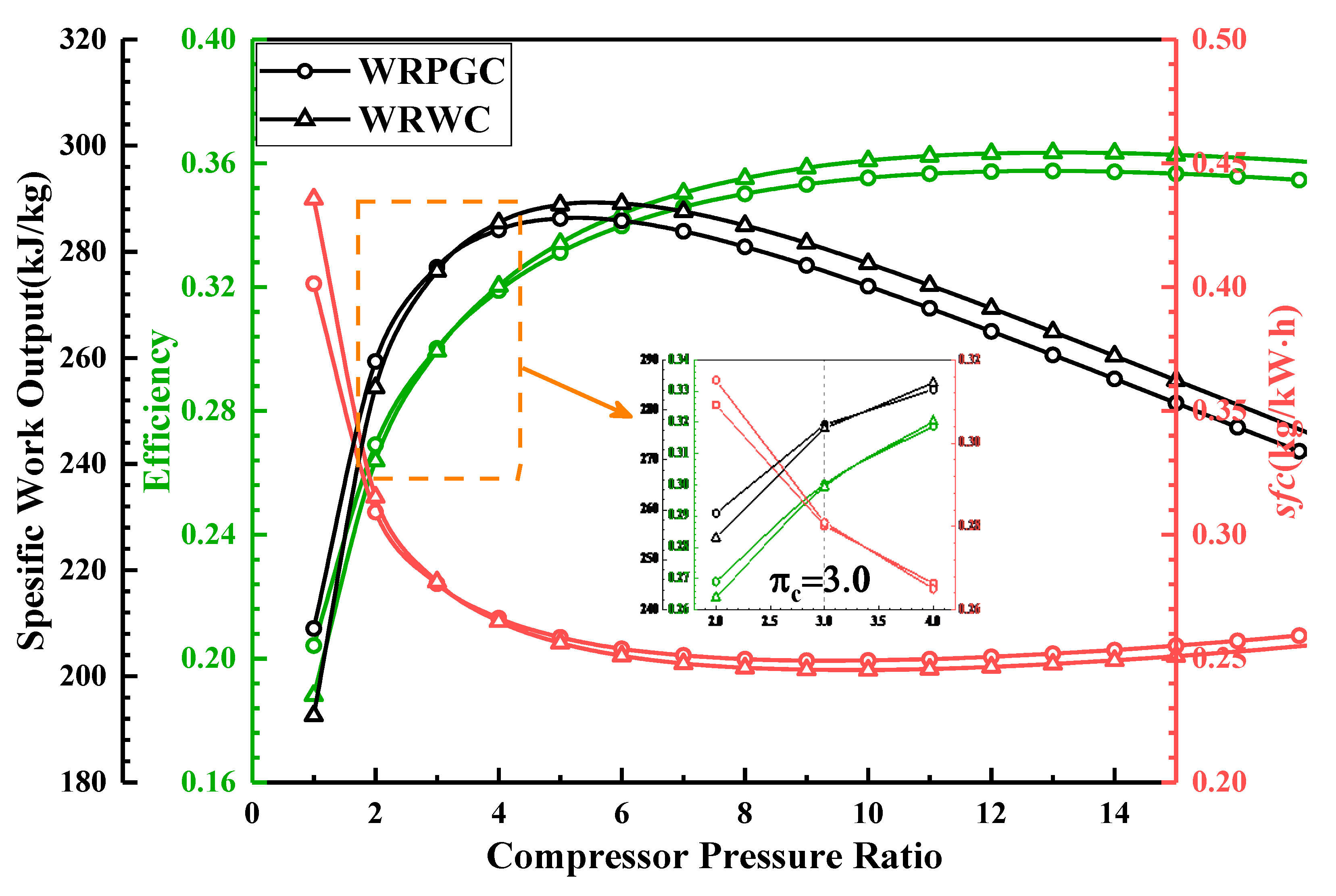
4.2. Performance Influence of Wave Rotor Precompression Ratio

Figure 8 presents the variation in the thermal efficiency, specific work, and specific fuel consumption with the precompression ratio of the wave rotor-embedded-in-the-baseline-engine cycle. The precompression ratio of the wave rotor ranges from 1.0 to 2.0. It can be observed that for both the WRPGC and WRWC, the thermal efficiency and specific work of the engine increase with the increase in the precompression ratio of the wave rotor. Meanwhile, the specific fuel consumption decreases with the increase in the precompression ratio, indicating an improvement in the engine performance as the precompression ratio of the wave rotor increases. When the precompression ratio of the wave rotor is 1.8, compared to the designed wave rotor pressure ratio of 1.2, the thermal efficiency of the WRPGC increases from 0.283 to 0.316, and the thermal efficiency of the WRWC increases from 0.305 to 0.345. Furthermore, the specific work output of the WRPGC increases from 201.0 kJ/kg to 224.6 kJ/kg, and the specific work output of the WRWC increases from 247.4 kJ/kg to 297.4 kJ/kg. As for the specific fuel consumption, the WRPGC reduces its specific fuel consumption from 0.301 kg/(kWh) to 0.269 kg/(kWh), and the WRWC reduces its specific fuel consumption from 0.278 kg/(kWh) to 0.245 kg/(kWh). It can be seen that increasing the precompression ratio of the wave rotor from 1.2 to 1.8 results in greater performance improvements for the pure-work wave rotor compared to the pure-pressure-gain wave rotor. Particularly, the specific work output shows more significant improvements with the increase in the precompression ratio. This indicates that increasing the precompression ratio is particularly effective for enhancing the performance of the pure-work wave rotor.
By calculating the relative increase in the thermal efficiency and specific work output and the relative decrease in the specific fuel consumption, a more intuitive understanding of the performance improvements under different wave rotor precompression ratios can be obtained, as shown in Figure 9. For the WRPGC, the relative improvements in the thermal efficiency and specific work output compared to the baseline engine are exactly the same. This can be explained using Equation (9), which can be written as T B T A = γ T 3 T 1 . It can be observed that the heat addition in the WRPGC is solely determined by T 3 and T 1 , independent of the wave rotor precompression ratio. As a result, the ratio of the thermal efficiency to the specific work output remains unchanged. When the wave rotor precompression ratio is 1.8, compared to the designed wave rotor pressure ratio of 1.2, the WRPGC exhibits an increase in both the thermal efficiency and specific work output relative to the baseline engine. The performance improvement in the thermal efficiency and specific work output for the WRPGC increases from 40.5% to 57.0%. And the specific fuel consumption shows an increase in performance improvement from 25.7% to 33.5%. For the WRWC, the thermal efficiency shows an increase in performance improvement from 51.4% to 71.5% compared to the baseline engine. The specific work output also experiences an increase in performance improvement from 73.0% to 108.0%. Additionally, the specific fuel consumption shows an increase in performance improvement from 31.2% to 39.3%.

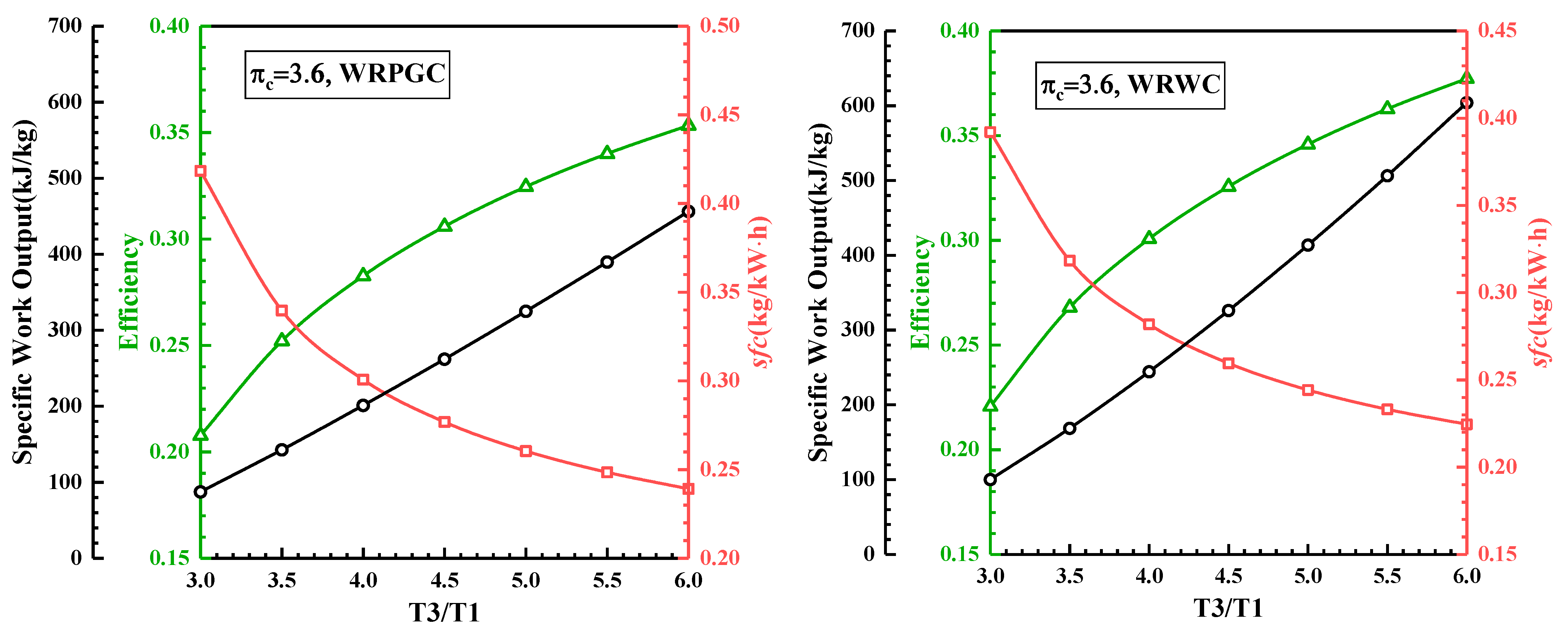
4.3. Performance Influence of Turbine Inlet Temperature

To investigate the influence of different turbine inlet temperatures on the performance of the wave rotor embedded in the baseline engine, Figure 10 presents the variations in the thermal efficiency, specific work output, and specific fuel consumption with respect to the turbine inlet temperature. The turbine inlet temperature is normalized using the reference T 3 / T 1 , and it ranges from 3.0 to 6.0. From the figure, it can be observed that both the WRPGC and the WRWC exhibit increases in their thermal efficiencies and specific work outputs with the increase in the turbine inlet temperature. Additionally, the specific fuel consumption decreases with the increase in the turbine inlet temperature, indicating a gradual improvement in the engine performance with higher turbine inlet temperatures. When the turbine inlet temperature ratio is 6.0, compared to the designed turbine inlet temperature ratio of 4.0, the WRPGC engine exhibits an increase in thermal efficiency from 0.283 to 0.353, while the WRWC engine shows an increase in thermal efficiency from 0.301 to 0.377. Moreover, the specific work output of the WRPGC engine increases from 201.0 kJ/kg to 456.1 kJ/kg, and the specific work output of the WRWC engine increases from 244.2 kJ/kg to 603.9 kJ/kg. As for the specific fuel consumption, the WRPGC engine experiences a decrease from 0.236 kg/(kWh) to 0.203 kg/(kWh), while the WRWC engine shows a decrease from 0.282 kg/(kWh) to 0.225 kg/(kWh). It can be observed that increasing the turbine inlet temperature ratio from 4.0 to 6.0 results in a greater improvement in the performance parameters for the WRWC engine compared to the WRPGC engine. Particularly, the enhancements in the work output and fuel consumption are more significant with the increase in the turbine inlet temperature. This indicates that increasing the turbine inlet temperature can achieve substantial improvements in performance, especially for the WRWC engine.
By calculating the relative increases in the thermal efficiency and specific work output and the relative decrease in the specific fuel consumption, a clearer understanding of the performance improvement under different turbine inlet temperature ratios can be obtained, as shown in Figure 11. For the WRPGC, the proportionate increases in the thermal efficiency and specific work output relative to the baseline engine are exactly the same. When the turbine inlet temperature ratio is 6.0, compared to the designed turbine inlet temperature ratio of 4.0, the WRPGC engine exhibits an increase in thermal efficiency and specific work output from 40.5% to 55.1% relative to the baseline engine, and the specific fuel consumption has a performance increase from 25.7% to 33.9%. Meanwhile, the WRWC engine shows a performance increase in thermal efficiency from 49.5% to 65.6% relative to the baseline engine, and the specific work output shows a performance increase from 70.8% to 105.3%. The specific fuel consumption also shows a performance increase from 30.3% to 38.0%.

4.4. Performance Influence of Fixed Peak Cycle Temperature

Figure 12 presents the variations in the thermal efficiency, specific work output, and specific fuel consumption for the two types of wave rotor-embedded baseline cycles, with respect to the compressor pressure ratio at the peak cycle temperature T B / T 1 = 6.0 . It can be observed that, regardless of the type of wave rotor cycle, both the thermal efficiency and specific work output of the engine initially increase and then decrease with the increase in the compressor pressure ratio. Furthermore, the specific fuel consumption follows a trend of initially decreasing and then increasing with the increase in the precompression ratio. It can be seen that when the compressor pressure ratio is greater than 3.0, whether it is the thermal efficiency, specific work, or specific fuel consumption, the performance parameters of the WRWC are superior to those of the WRPGC. This indicates that with a fixed turbine inlet temperature or peak cycle temperature, from mid- to high-pressure-ratio engine cycles, the WRWC exhibits a better performance. By zooming in on the region near the compressor pressure ratio of 3.0, it can be observed that the WRPGC exhibits a higher thermodynamic performance when the pressure ratio is below 3.0. This suggests that there exists a small range of pressure ratios under the fixed peak cycle temperature wherein the WRPGC outperforms the WRWC in terms of its output work and thermal efficiency. The WRPGC is more suitable for embedment in low-pressure-ratio baseline engines.

5. Conclusions

This study, based on a theoretical performance analysis, has obtained the following conclusions:
(1)
Based on the theoretical analysis of the WRC thermodynamic cycle, this study proposes the concepts of the wave rotor as a “wave rotor pressure-gain cycle” and a “wave rotor work cycle”. Performance parameters under different thermodynamic conditions are calculated;
(2)
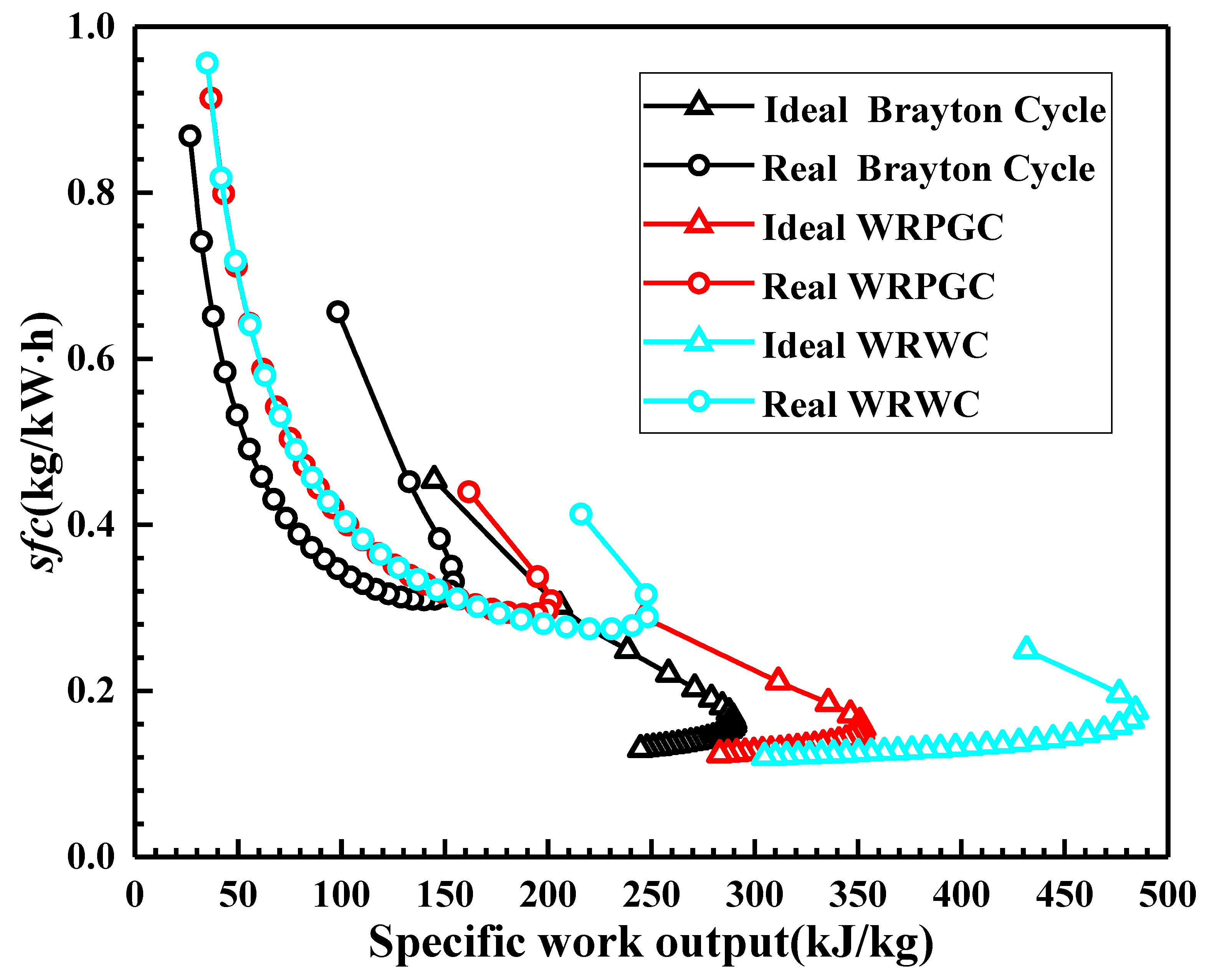
When the compressor pressure ratio exceeds 24.0, the thermal efficiency of the WRC cycle starts to fall below that of the Brayton cycle. For the baseline engine compressor pressure ratio of 3.6, the WRC cycle realizes performance improvements of 40.5% in the pressure-gain cycle and 49.5% in the work cycle, respectively;
(3)
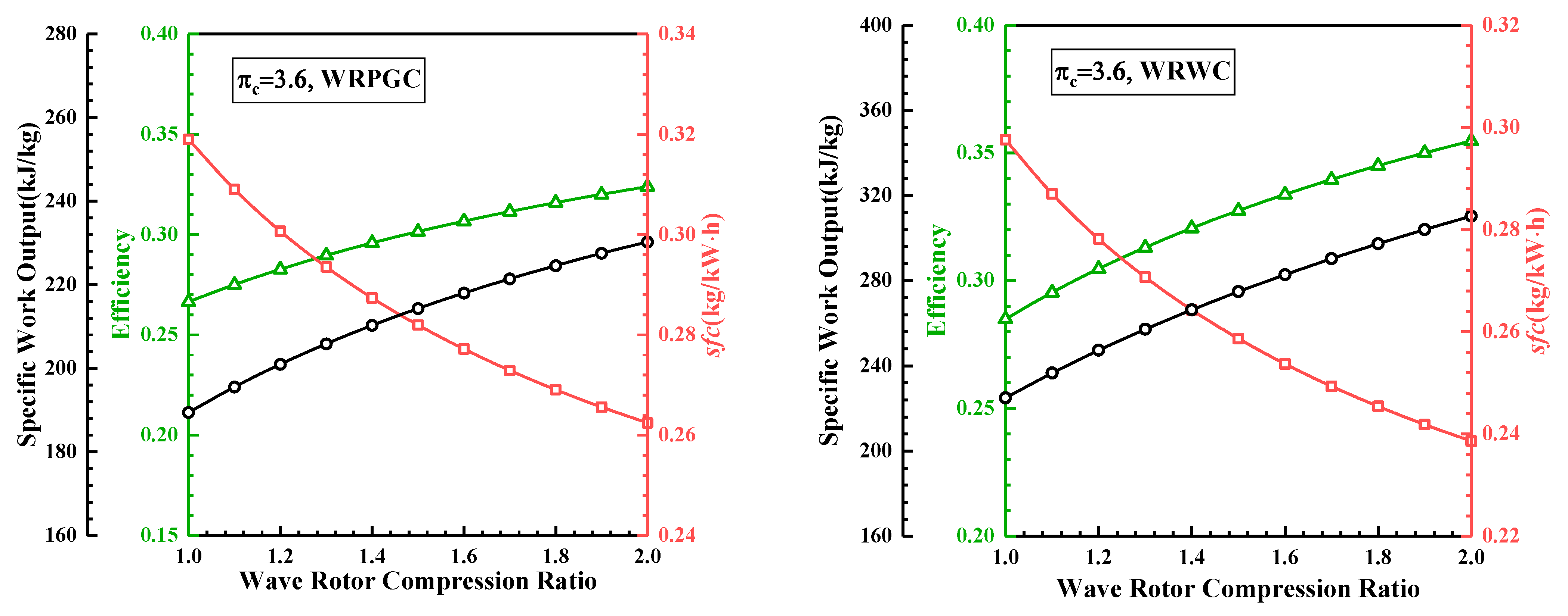
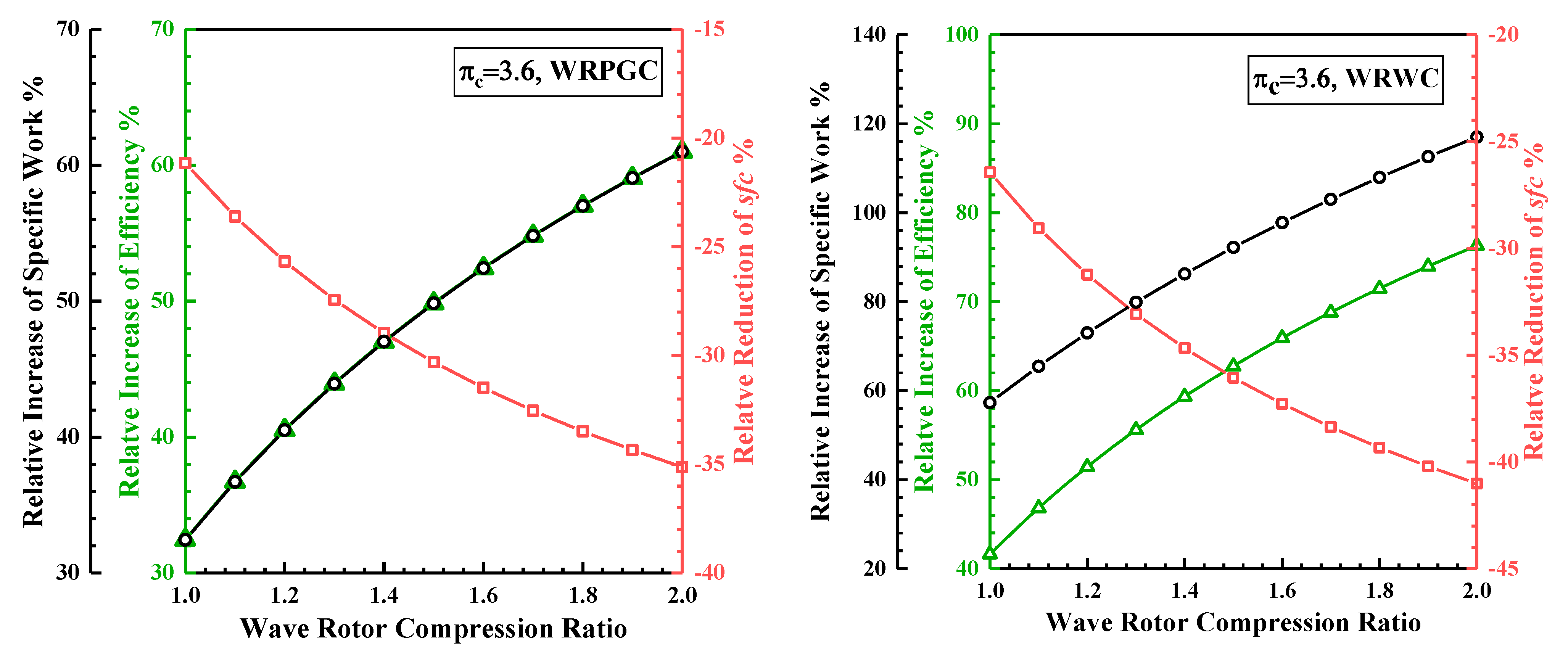
When the wave rotor precompression ratio is increased from 1.2 to 1.8, or when the turbine inlet temperature ratio is increased from 4.0 to 6.0, the WRWC has a better performance improvement compared to the WRPGC. Particularly, the increase in work output and the decrease in the specific fuel consumption are more significant with the increase in the turbine inlet temperature;
(4)
As the wave rotor peak cycle temperature is fixed, there is a small range of pressure ratios wherein the WRPGC exhibits a better work output and thermodynamic performance compared to the WRWC. The WRPGC is more suitable for integration into low-pressure-ratio baseline engines.

Author Contributions

Conceptualization, R.Z.; Methodology, E.G.; Software, Q.Y. and Z.N.; Investigation, Z.N.; Resources, J.L. and Q.Y.; Data curation, R.Z.; Writing—original draft, R.Z.; Visualization, E.G.; Supervision, J.L.; Funding acquisition, J.L. All authors have read and agreed to the published version of the manuscript.

Funding

This work was co-funded by the National Defense Technology Basic Research Project of China, grant numbers 1002TJA22010 and 1002TJA21007, and the Natural Science Foundation of Jiangsu Province, grant number BK20210278.

Data Availability Statement

The original contributions presented in the study are included in the article, further inquiries can be directed to the corresponding authors.

Conflicts of Interest

The authors declare that they have no known competing financial interests or personal relationships that could have appeared to influence the work reported in this paper.

References

  1. Kim, I.; Jin, H.; Ri, K.; Hyon, S.; Huang, C. Design methodology for combustor in advanced gas turbine engines: A review. Aircr. Eng. Aerosp. Technol. 2024, 96, 285–296. [Google Scholar] [CrossRef]
  2. Ergin, C.C.; Verstraete, T.; Saracoglu, B. The Design and Optimization of Additively Manufactured Radial Compressor of a Miniature Gas Turbine Engine. ASME J. Fluids Eng. 2024, 146, 7. [Google Scholar] [CrossRef]
  3. Haque, M.A.; Nemitallah, M.A.; Abdelhafez, A.; Mansir, I.B.; Habib, M.A. Review of fuel/oxidizer-flexible combustion in gas turbines. Energy Fuels 2020, 34, 10459–10485. [Google Scholar] [CrossRef]
  4. Abd El-Maksoud, R.M. Binary Brayton cycle with two isothermal processes. Energy Convers. Manage 2013, 73, 303–308. [Google Scholar]
  5. Jiang, Y.; Liese, E.; Zitney, S.E.; Bhattacharyya, D. Optimal design of microtube recuperators for an indirect supercritical carbon dioxide recompression closed Brayton cycle. Appl. Energy 2018, 216, 634–648. [Google Scholar] [CrossRef]
  6. Zhang, Y.; Li, H.; Han, W.; Bai, W.; Yang, Y.; Yao, M.; Wang, Y. Improved design of supercritical CO, Brayton cycle for coal-fired powerplant. Energy 2018, 155, 1–14. [Google Scholar] [CrossRef]
  7. Lefbvre A, H. Gas Turbine Combustion; Hemisphere Pubulishing Corporation: New York, NY, USA, 1983; pp. 94–95. [Google Scholar]
  8. Taamallah, S.; Vogiatzaki, K.; Alzahrani, F.M.; Mokheimer, E.M.; Habib, M.A.; Ghoniem, A.F. Fuel flexibility, stability and emissions in premixed hydrogen-rich gas turbine combustion: Technology, fundamentals, and numerical simulations. Appl. Energy 2015, 154, 1020–1047. [Google Scholar] [CrossRef]
  9. Koff, B. Gas Turbine Technology Evolution: A Designer’s Perspective. J. Propuls. Power 2004, 20, 577–595. [Google Scholar] [CrossRef]
  10. Akbari, P.; Nalim, R.; Mueller, N. A review of wave rotor technology and its applications. In Proceedings of the 2004 ASME International Mechanical Engineering Congress, Anaheim, CA, USA, 13–19 November 2004; pp. 1–23. [Google Scholar]
  11. Kailasanath, K. Review of propulsion applications of detonation waves. AIAA J. 2000, 38, 1698–1708. [Google Scholar] [CrossRef]
  12. Stathopoulos, P. Comprehensive thermodynamic analysis of the humphrey cycle for gas turbines with pressure gain combustion. Energies 2018, 11, 3521. [Google Scholar] [CrossRef]
  13. Heiser, W.H.; Pratt, D.T. Thermodynamic Cycle Analysis of Pulse Detonation Engines. J. Propuls. Power 2002, 18, 68–76. [Google Scholar] [CrossRef]
  14. Chen, L.; Lin, J.; Sun, F.; Wu, C. Efficiency of an Atkinson Engine at Maximum Power Density. Energy Convers. Manag. 1998, 39, 337–341. [Google Scholar] [CrossRef]
  15. Nalim, M.R.; Paxson, D.E. A Numerical Investigation of Premixed Combustion in Wave Rotors. J. Eng. Gas Turbines Power 1997, 119, 668–675. [Google Scholar] [CrossRef]
  16. Nalim, M.R. Assessment of Combustion Modes for Internal Combustion Wave Rotors. J. Eng. Gas. Turbines Power 1999, 121, 265–271. [Google Scholar] [CrossRef]
  17. Goldstein, A.W.; Klapproth, J.F.; Hartmann, M.J. Ideal Performance of Valved-Combustors and Applicability to Several Engine Types. Trans. ASME 1958, 80, 1027–1036. [Google Scholar] [CrossRef]
  18. Akbari, P.; Nalim, M.R. Review of Recent Developments in Wave Rotor Combustion Technology. J. Propuls. Power 2009, 25, 833–844. [Google Scholar] [CrossRef]
  19. Smith, C.; Snyder, P.; Emmerson, C.; Nalim, M. Impacts of the Constant Volume Combustor on a Supersonic Turbofan Engine. In Proceedings of the 38th AIAA/ASME/SAE/ASEE Joint Propulsion Conference & Exhibit, Indianapolis, IN, USA, 7–10 July 2002. [Google Scholar] [CrossRef]
  20. Li, H.; Akbari, P.; Nalim, R. Air-Standard Thermodynamic Analysis of Gas Turbine Engines Using Wave Rotor Combustion. In Proceedings of the 43rd AIAA/ASME/SAE/ASEE Joint Propulsion Conference & Exhibit, Cincinnati, OH, USA, 9 July 2007. [Google Scholar]
  21. Nalim, R.; Li, H.; Akbari, P. Air-Standard Aerothermodynamic Analysis of Gas Turbine Engines with Wave Rotor Combustion. J. Eng. Gas Turbines Power-Trans. ASME 2009, 131, 445–456. [Google Scholar] [CrossRef]
  22. Antonios, F. Gas turbine performance enhancement for naval ship propulsion using wave rotors. J. Mar. Eng. Technol. 2022, 21, 297–309. [Google Scholar] [CrossRef]
  23. Akbari, P.; Agoos, I. Two-Stage Wave Disk Engine Concept and Performance Prediction; SAE Technical Paper; SAE: Warrendale, PA, USA, 2017. [Google Scholar]
  24. Akbari, P.; Polanka, M.D. Performance of an Ultra-Compact Disk-Shaped Reheat Gas Turbine for Power Generation. In Proceedings of the 2018 Joint Propulsion Conference, Cincinnati, OH, USA, 9–11 July 2018. [Google Scholar]
  25. Sun, G.; Akbari, P.; Gower, B.; Mueller, N. Thermodynamics of the Wave Disk Engine. In Proceedings of the 48th AIAA/ASME/SAE/ASEE Joint Propulsion Conference and Exhibit, Atlanta, GA, USA, 30 July–1 August 2012. [Google Scholar]
  26. Li, J.Z.; Gong, E.L.; Wen, Q.; Wang, J.H. Effect of internal combustion wave rotor technology on performance of gas turbine engine. J. Aerosp. Power 2012, 27, 1928–1934. [Google Scholar]
  27. Briones, A.M.; Sekar, B.; Erdmann, T. Effects of Centrifugal Force on Flame Propagation Characteristics of Wave Rotor Combustor. J. Propuls. Technol. 2022, 43, 269–275. [Google Scholar]
  28. Gong, E.; Li, J.; Liu, B.; Han, Q. Analysis of Wave Rotor Combustor Leakage and Seal Problems. J. Propuls. Technol. 2016, 37, 1952–1957. [Google Scholar]
  29. Li, J.; Gong, E.; Yuan, L.; Li, W.; Zhang, K. Experimental investigation on pressure rise characteristics in an ethylene fueled wave rotor combustor. Energy Fuels 2017, 31, 10165–10177. [Google Scholar] [CrossRef]
  30. Paxson, D.; Kaemming, T. Foundational Performance Analyses of Pressure Gain Combustion Thermodynamic Benefits for Gas Turbines. In Proceedings of the 50th AIAA Aerospace Sciences Meeting including the New Horizons Forum and Aerospace Exposition, Nashville, TN, USA, 9–12 January 2012. [Google Scholar]
  31. Paxson, D.E.; Kaemming, T. Influence of Unsteadiness on the Analysis of Pressure Gain Combustion Devices. J. Propuls. Power 2014, 30, 377–383. [Google Scholar] [CrossRef]
  32. Wilson, J.; Paxson, D.E. Jet Engine Performance Enhancement Through Use of a Wave-Rotor Topping Cycle; Nasa Tm 4486; NASA: Washington, DC, USA, 1993.
  33. Jagannath, R.; Bane, S.P.; Feyz, M.E.; Nalim, M.R. Assessment of Incidence Loss and Shaft Work Production for Wave Rotor Combustor with Non-Axial Channels. In Proceedings of the 55th AIAA Aerospace Sciences Meeting, American Institute of Aeronautics and Astronautics, Grapevine, TX, USA, 9–13 January 2017. [Google Scholar]
  34. Hawthorne, W.R. R. Tom Sawyer Award Lecture: Reflections on United Kingdom Aircraft Gas Turbine History. J. Eng. Gas Turbines Power 1994, 116, 495–510. [Google Scholar] [CrossRef]
  35. Shen, W.; Tong, J. Engineering Thermodynamics; Higher Education Press: Beijing, China, 2007. [Google Scholar]
Figure 1. Schematic configuration of a WRC.
Energies 17 02074 g001
Figure 2. The working principle of the WRC. (a) Axial-flow wave rotor [33]. (b) Radial-flow wave rotor [25].
Energies 17 02074 g002
Figure 3. The ideal thermodynamic cycle of Brayton cycle, Humphrey cycle and RWRC cycle.
Energies 17 02074 g003
Figure 4. Comparison of thermal efficiencies between actual and ideal cycles.
Energies 17 02074 g004
Figure 5. Variation in thermal efficiency with specific work output.
Energies 17 02074 g005
Figure 6. Variation in specific fuel consumption with specific work output.
Energies 17 02074 g006
Figure 7. Performance enhancement of wave rotor engine cycle.
Energies 17 02074 g007
Figure 8. Variation in thermal efficiency, specific fuel consumption, and specific output power with wave rotor pressure ratio.
Energies 17 02074 g008
Figure 9. The relative changes in the thermal efficiency, specific fuel consumption, and specific work with various wave rotor pressure ratios.
Energies 17 02074 g009
Figure 10. Variations in thermal efficiency, specific fuel consumption, and specific work output with change in turbine inlet temperature ratio.
Energies 17 02074 g010
Figure 11. The relative changes in the thermal efficiency, specific fuel consumption, and specific work with various turbine inlet temperatures.
Energies 17 02074 g011
Figure 12. Variations in thermal efficiency, specific fuel consumption, and specific work output with compressor pressure ratio for fixed peak cycle temperature.
Energies 17 02074 g012
Disclaimer/Publisher’s Note: The statements, opinions and data contained in all publications are solely those of the individual author(s) and contributor(s) and not of MDPI and/or the editor(s). MDPI and/or the editor(s) disclaim responsibility for any injury to people or property resulting from any ideas, methods, instructions or products referred to in the content.

