Review

Comprehensive Review of Bearing Currents in Electrical Machines: Mechanisms, Impacts, and Mitigation Techniques

by
Tianyi Pei
1,2,
Hengliang Zhang
2,3,*,
Wei Hua
2,3 and
Fengyu Zhang
4
1
School of Electrical Engineering and Automation, Fuzhou University, Fuzhou 350108, China
2
Engineering Research Center of Electrical Transport Technology, Ministry of Education, Southeast University, Nanjing 210096, China
3
School of Electrical Engineering, Southeast University, Nanjing 210096, China
4
Power Electronics Machines and Control (PEMC) Research Group, University of Nottingham, Nottingham NG7 2RD, UK
*
Author to whom correspondence should be addressed.
Energies 2025, 18(3), 517; https://doi.org/10.3390/en18030517
Submission received: 29 December 2024 / Revised: 14 January 2025 / Accepted: 21 January 2025 / Published: 23 January 2025
(This article belongs to the Section F1: Electrical Power System)

Abstract

:
The present paper deals with a review on bearing currents in electrical machines, with major emphasis on mechanisms, impacts, and mitigation strategies. High-frequency common-mode voltages from the inverter-driven system have been found to be the main reason for bearing current leading to motor bearing degradation and eventual failure. This paper deals with bearing currents—electrical discharge machining (EDM) currents, circulating bearing currents, and rotor-to-ground bearing currents—and the various methods of their generation and effects that are harmful to the bearings and lubricants of a motor. Mitigation techniques, among which the following have been taken into account, are studied in this context: the optimization of PWM modulation, and the use of shaft grounding brushes, insulated bearings, and passive or active filters. Finally, advantages, limitations, and implementation challenges are discussed. A review comparing three-phase and dual three-phase inverters showed that, due to the increased degree of freedom in modulation strategies, it is possible to eliminate common-mode voltages through active modulation techniques. Such added flexibility will reduce the risk of bearing currents effectively. It also highlights future research directions in bearing current suppression, including the development of multi-phase motor systems, real-time monitoring technologies with artificial intelligence, and the use of new insulation materials for the enhancement of bearing reliability. The results obtained should guide future research and engineering practices in suppressing bearing currents to improve motor durability with high performance.

1. Introduction

In modern industry, motors are widely used in various drive systems as the core of the conversion between mechanical energy and electrical energy. However, since the birth of motors, there has been the problem of bearing current. In particular, the problem caused by bearing current is further amplified in the widespread application of PWM inverter-driven motors [1,2]. Especially in large motors, such as wind turbine generators, the phenomenon of bearing current is more obvious [3,4,5]. IEEE research points out that bearing failure is the main cause of motor failure. By statistically analyzing the types of failures that occurred in 1141 motors with horsepower greater than 200 and running time less than 15 years [6,7,8], the statistical results show that bearing failure and stator insulation-related failures are the most common causes of motor failures.
The causes of bearing current are complex, including electromagnetic induction effect, electrostatic induction effect, and high-frequency effect under inverter drive. In the traditional sinusoidal power supply mode, the shaft voltage and bearing current mainly come from electromagnetic imbalance. In the inverter drive, the shaft voltage and bearing current phenomena caused by the high dv/dt characteristics of the common-mode voltage are more significant. In addition, external factors such as the electrostatic effect of external loads and the capacitive coupling effect of the excitation system may also have a significant impact on the shaft voltage and bearing current [9].
It can be seen that, with the rapid popularization of Inverter-driven systems, the problem of bearing current has attracted considerable attention in recent times among all modern industrial motor applications. On the other hand, motor drive technology tends toward high efficiency and high-power density, owing to the main drives of renewable energy systems such as wind power generation and photovoltaic power generation. However, the high-frequency switching behavior of the inverter drive can result in significant common-mode voltages, which can induce bearing currents. These bearing currents can lead to premature bearing failure, lubricant degradation, and severe mechanical damage, which not only increases maintenance costs, but also poses a threat to system stability and reliability. In particular, for wind turbines with complex operating conditions, frequently fluctuating loads, and high power, the bearing current problem is becoming increasingly severe. All these challenges have made it imperative for researchers and engineers to come up with more effective mitigation strategies to guarantee long-term reliability in renewable energy systems.
Although the research on shaft voltage and bearing current has a history of nearly a hundred years, there are still many fragmentations and shortcomings in the existing research. Under the drive of PWM inverter, common-mode voltage is the “culprit” that causes motor shaft voltage and bearing current. A deeper study on it is needed to suppress bearing current. Currently, many methods have been put forward for bearing current mitigation, such as optimizing PWM modulation, shaft grounding brushes, insulation bearings, and so on, but the existing research does not show a comprehensive comparison of the implementation effect, cost, and complexity. Insufficient research into the multi-phase motor system: Most of the literature focuses on three-phase motor bearing current problems, while the effective bearing currents and mitigation methods are less studied for multi-phase motor systems. Based on the above background, the purpose of this study is to fill these knowledge gaps, systematically review the generation mechanism, detection methods, and mitigation strategies of bearing currents, and focus on the practical applicability and effectiveness of these strategies, so as to provide scientific guidance for motor reliability design and fault prevention. Furthermore, research into multi-phase motors and complex modulation technologies has emerged as a research frontier due to increasing demands from applications such as electric vehicles and renewable energy systems. Optimizing multi-phase motor modulation with respect to the mitigation of bearing current problems will go a long way in enhancing the performance and operational and maintenance costs of such motors. Therefore, this paper aims to comprehensively review the current status of research on shaft voltage and bearing current, including the principles of their phenomena, hazards to bearings, mathematical equivalent models, and commonly used mitigation measures for bearing current in industry. At the same time, this article will summarize the current research on common-mode voltage suppression, point out the shortcomings, and propose future research directions to provide a reference for researchers in this field.
In this paper, a systematic literature screening process was adopted to find high-value studies related to motor bearing current, which would be able to provide sufficient literature support for the analysis of the mechanism, its influence, and mitigation strategies. We performed the literature search mainly using Web of Science and the Google Scholar database. The keywords used in search were “bearing current”, “shaft voltage”, “PWM modulation”, “common-mode voltage”, etc. To include the results, Boolean logic was combined with AND/OR logical operations between these keywords. The time range was 1900 to 2024, and the papers were all in English. The exclusion criteria included the following: papers without experimental or theoretical support; research fields unrelated to motor bearing current; and informal publication or gray literature including, but not limited to, technical reports, non-public papers, etc. Literature screening followed the PRISMA (Preferred Reporting Items for Systematic Reviews and Meta-Analyses) process, and the specific flow chart is shown in Figure 1.

2. Bearing Current in Conventional Sine Wave Power Supply Mode

The phenomenon of bearing current was mentioned as early as the 1920s, but in early studies, there was confusion in the interpretation of the concept of shaft voltage. Reference [9] made a detailed distinction between the two. The shaft voltage refers to the voltage at both ends of the rotor shaft; the bearing voltage refers to the voltage between the rotor shaft and the stator casing grounding point.

2.1. Phenomenological Principle

The bearing current in AC direct-drive motors can be divided into three types according to the different ways in which they are generated:
  • The voltage induced at both ends of the shaft due to the tangential magnetic flux.
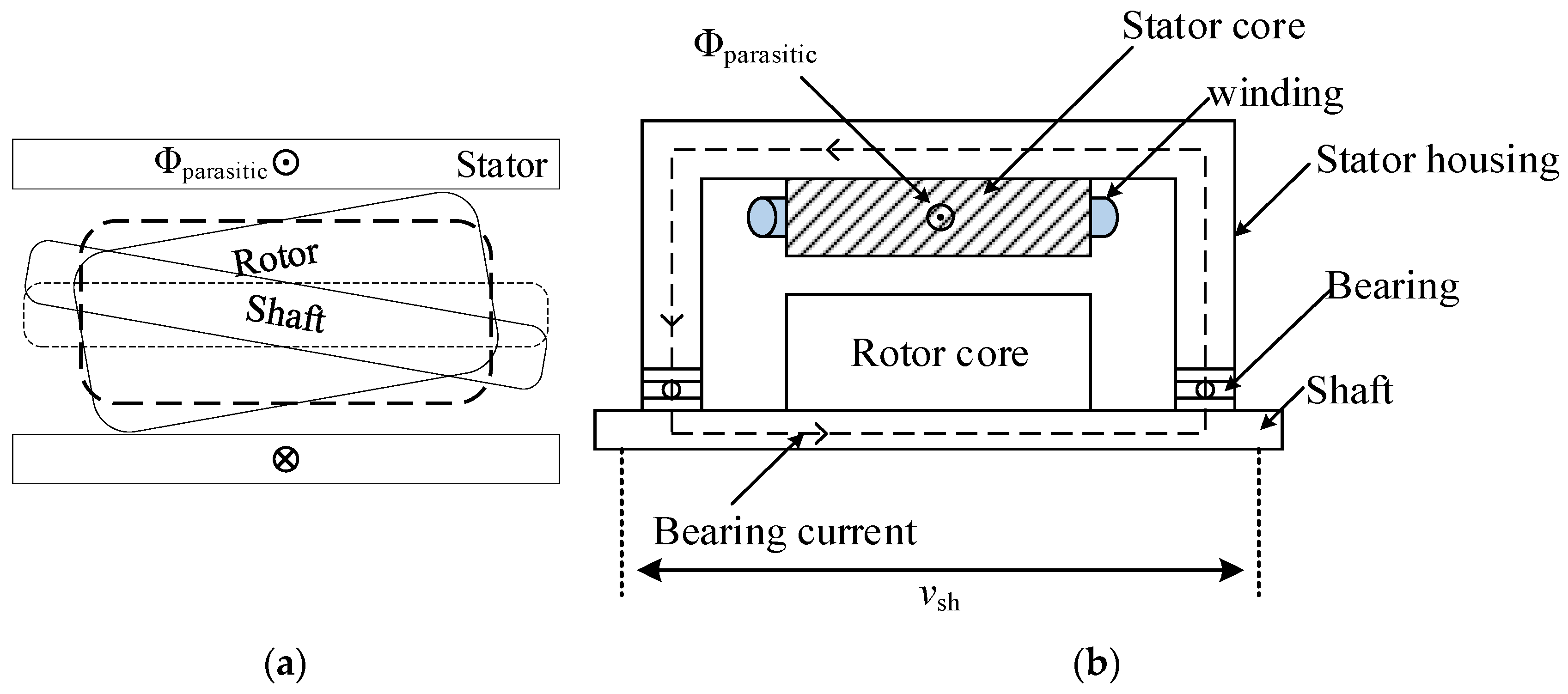
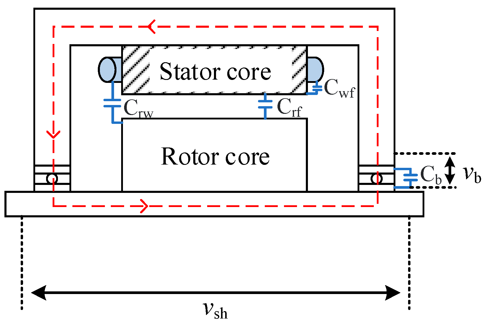
The author Alger pointed out in the literature that bearing currents also occur in conventional AC-powered motors. The main reason for this is that errors in the motor’s mechanical parameters, such as rotor eccentricity, winding asymmetry, etc., lead to asymmetric magnetic flux [10]. As shown in Figure 2a, the asymmetric magnetic flux Φparasitic will induce shaft voltage vsh on both sides of the shaft. When the shaft voltage generated by the asymmetric magnetic flux is greater than the threshold that the system can withstand, a circulating current will be generated in the motor system. This type of current is called circulating shaft current, and its main flow path is “drive end bearing-motor shaft-non-drive end bearing-stator housing” as shown in Figure 2b. European and American standards give the peak values of shaft voltage vsh, namely 500 mV [11] and 300 mV [12]. When it is greater than this value, insulating bearings should be used.
2.
The voltage induced in the bearing due to the axial magnetic flux.
Axial flux is a phenomenon caused by magnetic asymmetry inside the motor. This asymmetry may come from asymmetric winding connections, disconnected rotor bars, uneven air gaps, etc. This flux passes through the bearing in an axial manner, flows through the stator frame, and then returns to the rotor shaft through the bearing at the other end, thus completing a closed loop. This flux induces current in the bearing, forming a unique current path inside the bearing.
The characteristic of the bearing current caused by axial flux is that its path is different from that of an ordinary circulating current. It mainly forms a loop inside a single bearing instead of circulating in the entire motor system. Due to the particularity of this current path, conventional bearing insulation measures have limited effect on it. Therefore, the method to eliminate this axial flux is mainly to introduce non-magnetic barriers in the magnetic circuit, such as using non-magnetic bearings, bearing seats or shaft materials, to increase the magnetic resistance of the magnetic circuit, thereby reducing the generation or flow of magnetic flux [10,13].
3.
Shaft-to-ground voltage due to electrostatic effect.
This phenomenon is externally derived from the load, for example, from the friction of belts and pulleys, or the friction between blades and wet steam in low-pressure turbines [10,14], as shown in Figure 3a. The electrostatic effect causes the charge to accumulate on the rotor shaft, which has a capacitive effect. When the bearing voltage vb increases and charges the breakdown threshold of the lubricating oil film, it will cause breakdown. However, the breakdown threshold mainly depends on the state of the insulating oil film. This breakdown forms the so-called “electro-spark discharge machining” (EDM) current pulse and occurs inside the bearing, as shown in Figure 3b.

2.2. The Harm Caused by Bearing Current and Its Solution

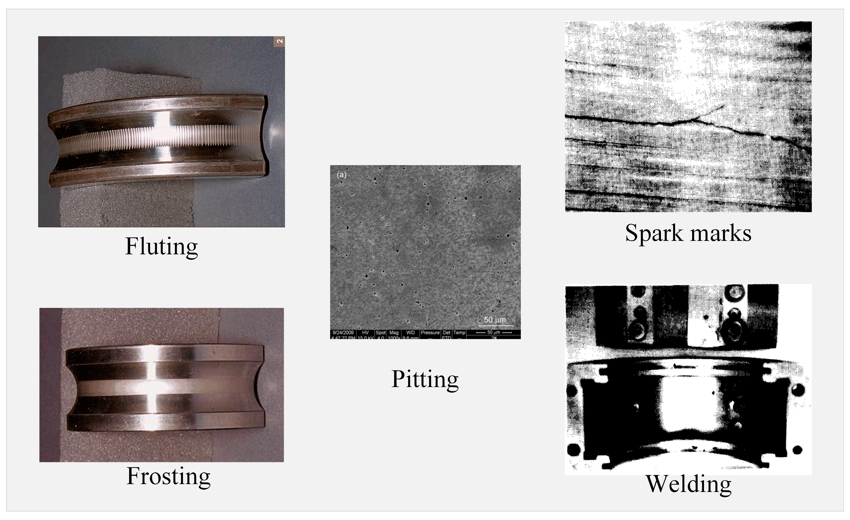
Depending on the type of bearing current, the damage to the bearing is different [15]. At present, the fault types of low-frequency bearing current can be divided into the following types: frosting, pitting, spark tracks, and welding, which have been described in detail [13] (Figure 4). The frosted surface is mainly formed by electric spark discharge (EDM) [16], which is more obvious under heavy load. Pitting contains larger “pits” and is more serious than frosting. It is mainly due to the low impedance characteristics of the bearing. When the temperature is high, the insulating oil film undergoes chemical changes, resulting in pitting on the bearing. The arc track is irregular in shape and has a certain deviation from the direction of rotation. Welding is related to a large amount of current passing through the bearing, and the metal molten area formed can be observed with the naked eye [13,17]. The physical explanation for these phenomena has been described in detail in [16,18]. The damage is usually examined under a microscope to confirm its source, which may be mechanical, chemical, or electrical. For motors driven by inverters, the phenomenon of fluting will occur due to the high-frequency common-mode voltage phenomenon [16]. The specific reasons for this phenomenon are described in detail in Section 2.
Under traditional AC power supply conditions (50/60 Hz sinusoidal power supply), the methods for suppressing motor shaft current mainly focus on insulation, grounding optimization, and design improvement. Insulated bearings and ceramic bearings effectively suppress circulating bearing currents by breaking the circulation path or increasing resistance, while shaft grounding brushes provide a low impedance path for electrostatic induction currents caused by shaft voltage [13], but require regular maintenance. In addition, improving motor design to balance the magnetic circuit, eliminate residual magnetic flux, and optimize the electrical properties of grease (such as high conductivity or high breakdown voltage grease) can also reduce the risk of bearing current damage [10,13]. By monitoring shaft current and shaft voltage and performing preventive maintenance, problems can be discovered and solved in a timely manner [17]. In short, different types of shaft currents require targeted suppression measures, combined with motor design optimization and operating parameter adjustment to achieve effective control of the shaft current. In recent years, research has mainly focused on the bearing current phenomenon caused by PWM inverters.

3. Bearing Current Phenomenon Caused by PWM Inverter

With the continuous development of power electronic devices, the types of variable frequency drive systems using IGBT inverters have increased dramatically [19]. Traditional linear drive systems have the characteristics of low loss, low noise, and smooth torque, but they cannot adjust the motor speed and are limited in applicable scenarios [20,21]. Compared with traditional drive systems, motor systems driven by inverters can adjust the speed according to real-time conditions to save energy. However, at low switching frequencies, variable frequency drive systems will generate additional losses, additional noise, and torque fluctuations at rated motor speeds, and have poor dynamic performance [22,23,24]. At present, the additional losses, noise, and torque fluctuations can be reduced by increasing the switching frequency of the switching device, and the dynamic performance of the system can be improved. However, high-frequency signals and motor parasitic parameters will have a serious impact on the bearings [25,26,27,28].

3.1. Phenomenon Principle

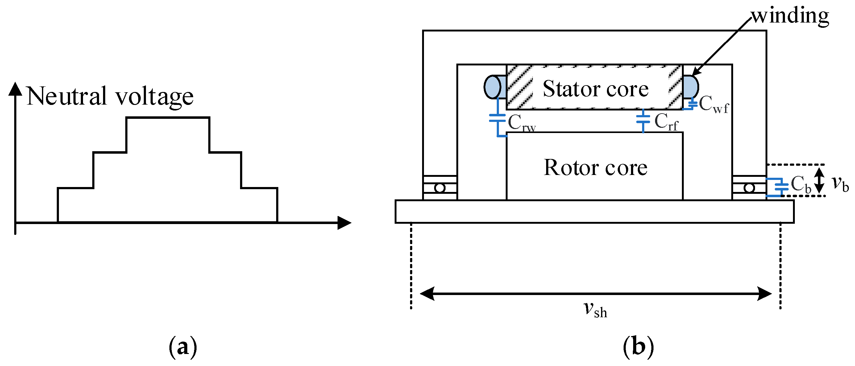
Since the three-phase voltage output by the inverter is not a traditional sinusoidal voltage, but a sinusoidal voltage equivalent to a square wave pulse, the sum of the three phases is not zero [26,29], as shown in Figure 5a. Therefore, when the switching frequency is high, the high-frequency differential mode voltage will cause the stator winding to face greater voltage stress, and due to the existence of high-frequency common-mode voltage, the system will have greater electromagnetic interference problems. Under the action of high-frequency signals, the parasitic capacitance of the motor itself will be stimulated [29]. As shown in Figure 5b, the high-frequency signal will have a serious impact on the bearings through the parasitic capacitance.
The bearing current phenomenon in the inverter drive system is mainly caused by the common-mode voltage generated by the inverter. Under the influence of the motor parasitic parameters, part of the high-frequency common-mode voltage will pass through the parasitic capacitance between the winding and the rotor to generate bearing voltage on both sides of the bearing. When the bearing voltage is greater than the threshold, it will cause high-frequency bearing current [25,30]. Another part of the common-mode voltage will pass through the coupling capacitance between the winding and the stator housing to generate ground current. If it is not suppressed, the axial magnetic flux generated will induce voltage at both ends of the shaft. When it exceeds the threshold, it will seriously affect the service life of the bearing [26,31]. At present, according to the different flow paths, the bearing currents with greater hazards generated by the inverter can be divided into the following three types (the charging current generated by dv/dt has less impact on the reliability of the bearing [32]):
  • Electrical discharge machining bearing current;
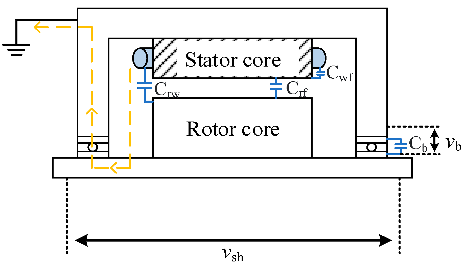
When the motor rotates, the thickness of the insulating oil film in the bearing is greater than that when the motor is stationary. At this time, the bearing acts as a capacitor Cb. When the system is running, the high-frequency common-mode voltage will charge and discharge Cb. At this time, the current in the bearing is small and can be ignored. When the voltage across the bearing is greater than the breakdown voltage of the insulating oil film, spark discharge will occur inside the bearing [28]. The current at this time is called EDM bearing current. This spark discharge phenomenon will have a serious impact on the life of the bearing. At this time, the flow path of the EDM current is a “winding-rotor core-motor bearing-stator housing or system grounding point” [33,34,35], as shown in Figure 6.
2.
High-frequency circulating bearing current.
Due to the parasitic capacitance between the stator winding at the drive end and the motor housing, the common-mode current generated by the common-mode voltage will flow directly out through this parasitic capacitance, which will cause the current flowing into the stator winding to be unequal to the current flowing out of the stator winding. This will generate a high-frequency tangential magnetic flux inside the motor, which will induce shaft voltage at both ends of the motor shaft. When this shaft voltage is greater than a certain threshold, a loop bearing current will be generated inside the motor [26]. This loop current will form a loop in the device, and its path is “drive end bearing-shaft-non-drive end bearing-stator housing”, as shown in Figure 7, which will cause equipment failure, damage, and shortened service life [36,37,38].
3.
Rotor-to-ground bearing current.
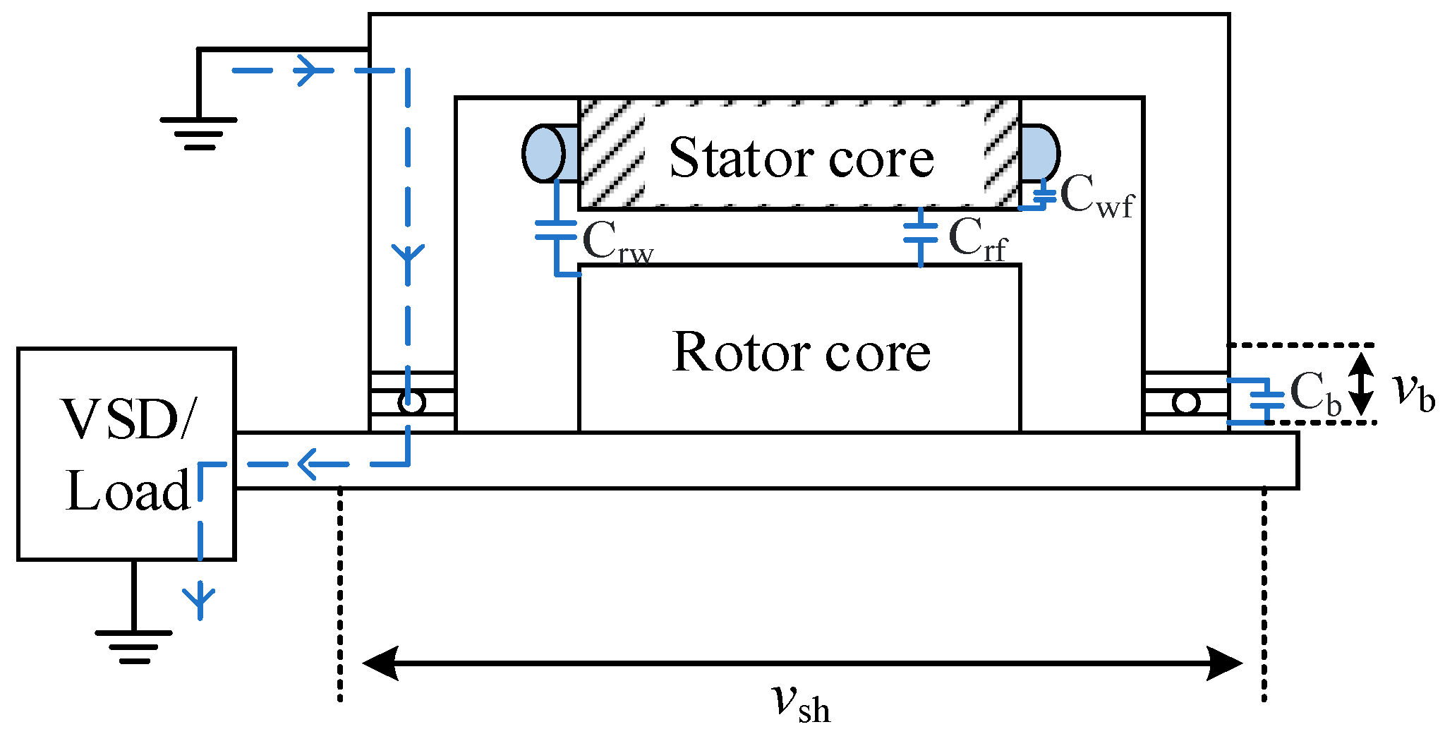
If the inverter motor has poor grounding, the casing potential will increase, causing the rotor core grounding impedance to decrease. At the same time, the stator casing grounding impedance will increase, generating a current that flows from the grounding line into the rotor bearing. The propagation path of this current is a winding-stator casing-motor bearing-rotor shaft-load grounding point/inverter grounding point [39], as shown in Figure 8. This current will generate heat and electromagnetic fields on the bearing and its surrounding components, causing great harm to the bearing and shaft [40,41,42].
The performance and importance of bearing currents differ in various industrial scenarios concerning the level of motor power, application area, and operating conditions. In general, the circulating bearing current is more relevant for high-power motors like wind turbines and industrial drive motors. That is because in high-power devices, the size of bearings and winding leakage inductance are usually larger, which results in more significant magnetic induction effects and thus circulating bearing currents. Moreover, the complicated grounding system of high-power equipment will also improve the conduction path of common-mode voltage, which makes the rotor-to-ground current occur more easily. For motors with lower power, such as household appliances and small industrial equipment, EDM currents are more likely to become dominant. This is because, with a thinner lubricant film and smaller bearing size, it is much easier to exceed the voltage breakdown threshold that may result in spark discharge. In particular, for small devices driven by inverters, large common-mode voltage fluctuation caused by high dv/dt significantly increases the occurrence probability of EDM current.
Most industrial fields, such as those in production lines, pumps, and fans, work under the conditions of constant load and speed. In such cases, circulating bearing currents and rotor ground currents are usually more important. Long-term operational stability is extremely important in industrial applications, and more consideration should be given to effective mitigation strategies against circulating currents. Most motors of electric vehicles face high dynamic loads and variation in speeds. That is what makes the EDM current dominant in operation, especially in high-speed and frequent start-stop processes where the fluctuation of the common-mode voltage is more violent. Hence, bearing current mitigation strategies in the automotive field tend to be more inclined toward suppressing EDM currents by using insulated bearings and optimized PWM modulation strategies.
In general, circulating bearing currents show a tendency toward increased amplitude due to high loads and speeds, while EDM currents are more expected to occur under low loads and speeds because of difficulty in maintaining adequate thickness and uniformity in the lubricant film. The change in lubricant property under humidity and contamination conditions could have a great impact on the occurrence probability of EDM current. High temperatures accelerate the aging of the lubricant and reduce the electrical insulation property of the oil film further, therefore increasing the possibility of electric spark discharge.

3.2. Mathematical Model

In order to analyze the impact of bearing current on the bearing, it is necessary to establish an accurate mathematical model. The potential difference can form an electric field between the conductive parts of the motor, such as stator winding, rotor, and housing. The parts are isolated from each other by air and insulating materials, which means the existence of the electric field will inevitably lead to the generation of capacitive effect. Typical parasitic capacitance includes the following: stator winding-to-rotor, where the winding and the rotor are coupled through the air gap to form stator–rotor parasitic capacitance; stator winding-to-housing, where stator-housing parasitic capacitance is also formed between the winding and the grounded housing; and rotor-to-housing, where the rotor and the housing are coupled through the air gap or this insulating medium to form rotor–housing parasitic capacitance. Due to the insulation medium laid between the inner ring of a bearing and the ball, in the bearing there also has parasitic capacitance.
In order to explain the phenomenon of EDM current, the common mode equivalent model of the motor has been proposed [28,30], as shown in Figure 9.
Where Cws is the parasitic capacitance between the winding and the stator housing, Cwr is the parasitic capacitance between the winding and the rotor, Crf is the parasitic capacitance between the rotor and the stator housing, and the bearing is equivalent to the capacitor Cb. When the EDM phenomenon does not occur, the shaft voltage can be generated by the voltage division effect of Cb and Cwr.
Regarding the current of EDM, high-frequency signals have been in position to charge the bearing capacitance mainly through parasitic capacitance between the stator winding and rotor. However, for the measurement purpose of the magnitude of charging amplitude, a bearing voltage ratio is considered introducing the concept of BVR according to voltage division principle of capacitances Cwr, Crf and Cb. The larger the Cws, the larger the voltage divided on the bearing, and the greater the probability of generating bearing current. Therefore, BVR is usually used as an important indicator for measuring bearing current. This normally involves the inner ring, rolling elements, and outer ring in a path of EDM current. Local stress concentration due to uneven current distribution and superimposition of thermal and mechanical stresses can cause surface damage, pitting, or fatigue cracks. Bearing design, material properties, lubrication conditions, operating, and electrical parameters could have a substantial effect on stress distribution. These improvements—optimization of the bearing geometry, the selection of high-conductivity material, the improvement of the lubrication condition, and the technical measures of suppressing current—provide an effective way of reducing the stress concentration. The device life elongation of bearings contributed to the increase in reliability of motor systems.
The influence of the high-frequency circulating shaft current is mainly related to the parasitic capacitance between the winding and the stator housing. When Cws is bigger, the more high-frequency common-mode signal can flow into stator housing grounding via Cws. The difference between the current flowing into the winding and that flowing out of the winding will then become larger due to the interference and unbalance of magnetic flux, which causes this to be bigger and larger. According to Faraday’s law of electromagnetic induction, this will increase the shaft voltage and hence increase the circulating bearing current. In addition, in actual engineering, because there is grounding impedance, it will cause greater coupling between the winding and the ground, which will cause greater circulating bearing current.
The definition of BVR is given in the literature [28] to describe this voltage division phenomenon. Therefore, the value of the bearing voltage Vb can be determined by the size of BVR and the amplitude of the common-mode voltage. The literature points out that when BVR can be used as an indicator of the EDM phenomenon: when the value of BVR is greater than 10%, the probability of EDM occurring in the bearing is high [39]. The literature [3] shows that the BVR value of the doubly fed induction generator is as high as 97.9%, which also points out why the doubly fed induction generator has a more serious EDM phenomenon. The calculation formula of BVR is as follows:
B V R = C w r / ( C w r + C r f + C b )
At present, the main calculation methods for motor parasitic capacitance include analytical methods, and the two-dimensional finite element method (2D-FEM) and three-dimensional finite element method (3D-FEM).
The analytical method simplifies the motor structure into a symmetrical or regular geometric model and calculates the parasitic capacitance value in combination with electric field theory. The advantage of this method is that it has a fast calculation speed and is suitable for preliminary evaluation and parameter sensitivity analysis [43]. For example, reference [44] proposed an analytical model that can efficiently calculate the parasitic capacitance from the winding to the frame and bearing. Crf is usually modeled as a cylindrical capacitor and needs to be corrected by considering the Carter coefficient of the open slot effect. Cws is approximated as a parallel plate capacitor, and the electrode area is the circumference of the stator slot multiplied by the axial length of the core. Cwr is decomposed into multiple parallel plate capacitances, including the air gap, slot wedge, and upper insulation capacitance. However, the main disadvantage of the analytical method is that its assumptions are too idealized and ignore the geometric complexity and nonlinear factors of the motor, so there are certain limitations in its accuracy.
The two-dimensional finite element method simplifies the three-dimensional problem into a plane problem by modeling the motor cross section to calculate the parasitic capacitance. Its advantages are high computational efficiency and better consideration of geometric details than analytical methods [45]. Reference [46] used the two-dimensional finite element method to calculate the capacitance and compared it with the analytical method. The comparison showed that there were large differences in the calculation results. This can be explained by the fact that the simplified model ignored the edge effect. Reference [47] used 2D-FEM to study the parasitic capacitance matrix of the motor driven by PWM inverter and analyzed the influence of switching frequency on the parasitic capacitance. In reference [3], the parasitic capacitance of the doubly fed induction generator was calculated by way of the two-dimensional finite element method. Although the two-dimensional method can capture more geometric characteristics, it ignores the end effect and three-dimensional distribution of the motor, so the accuracy is not enough to cope with complex motor structures.
The three-dimensional finite element method can accurately capture the end effect and complex electric field distribution by fully modeling the three-dimensional structure of the motor. By constructing a detailed motor geometric model (including stator windings, rotor components, and end windings), combined with the boundary setting of actual operating conditions and the nonlinear characteristics of the material, the distribution of parasitic capacitance can be accurately simulated. Reference [48] used 3D-FEM to simulate the characteristics of common-mode current and circulating bearing current in the study, and verified its accuracy under high-frequency operation. Reference [49] further verified the effectiveness of this method in capturing high-frequency effects and the influence of mechanical and thermal factors on capacitance through experiments. In addition, reference [50] demonstrated the guiding role of 3D-FEM in the design and optimization of complex motor structures by studying the influence of end windings on parasitic capacitance. However, its disadvantages are its high calculation cost and time, its high requirements for hardware resources, and its unsuitability for large-scale parameter scanning and preliminary design stage research.
In short, the analytical method is suitable for the rapid estimation of simple motor geometry, especially in the early design stage, and can quickly provide reference values based on motor parameters. 2D-FEM is suitable for the calculation of planar symmetrical structures. In a two-dimensional plane, the parasitic parameters of the motor are calculated under an electrostatic field environment. The accuracy is higher than the analytical method, and it can strike a balance between calculation accuracy and efficiency. 3D-FEM is suitable for complex asymmetric structures and high-precision scenarios. For the motor, the end effect of the winding is thought to affect the motor parasitic parameters, but the calculation time is relatively long, so it is suitable for the final verification stage. The details are shown in Table 1, detailing the application of the finite element method (FEM) in the analysis of parameters in different fields (such as deformable solid mechanics, heat transfer, fluid mechanics, electrodynamics, and topology optimization). Reference [51] shows the application of the finite element method in geomechanical modeling, such as the simulation of stress–strain behavior of deformable solids in complex environments. Reference [52] illustrates the role of the finite element method in urban geomechanics and underground dynamic analysis. These practical cases highlight the adaptability of the finite element method to specific challenges in geomechanical modeling.
When the motor operates at a rated speed, an insulating oil film with a certain thickness will be formed between the ball and the raceway, which can be equivalent to a capacitor. However, in reality, whether the ball and raceway have metal contact is full of randomness [25], which is related to many factors, such as temperature, speed, load, etc. According to the randomness of the insulating oil film, the bearing current can be divided into the following three categories [53]:
Capacitive current: The grease behaves as a capacitor. The capacitive current is driven by the dv/dt (voltage change rate) of the bearing voltage and flows when the lubricating film is not broken down.
Ohmic current: When the grease has a high conductivity, the bearing current mainly flows in the form of ohmic current, which causes almost no damage to the bearing surface.
EDM current: When the lubricating film breaks down, a high-intensity transient pulse current will pass through the lubricating film, causing ablation and grooves (spark damage) on the bearing surface.
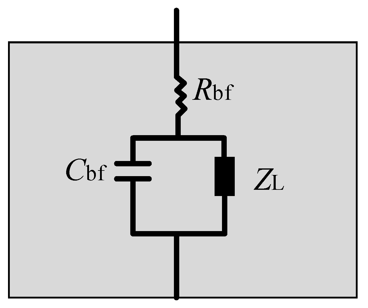
Reference [28] provides a method for calculating the contact area between the ball and the raceway, which is mainly obtained through the Hertz contact theory. As for the equivalent model of the bearing, as shown in Figure 10, reference [25] makes a detailed explanation. When the motor is at low speed or stationary, there are many rough contact points between the ball and the raceway. At this time, the bearing can be equivalent to a low impedance; when the motor is above the rated speed, the insulating oil film will form a certain thickness. At this time, the bearing can be equivalent to a capacitor; in addition, the parallel nonlinear impedance ZL is used to represent various nonlinear factors in the system operation, such as temperature, etc. [54];
In motor systems, bearing capacitance is an important parameter for bearing current analysis. Its calculation methods mainly include the analytical method and the finite element method. The analytical method is usually based on dielectric theory, and the bearing is regarded as a parallel plate capacitor model. The calculation is performed using the formula Cb = ε*A/d, where ε is the equivalent dielectric constant of the oil film, A is the contact area, and d is the oil film thickness [44]. This method is simple and intuitive, and suitable for preliminary estimation, but it ignores the non-uniformity of the contact surface between the ball and the raceway.
At present, some studies have proposed using the finite element method to calculate bearing capacitance. The bearing is modeled by electromagnetic field analysis [43], and the oil film thickness is simulated by combining the elastohydrodynamic lubrication theory, which can accurately calculate the spatial distribution of bearing capacitance. FEM can take into account the influence of materials, electric field distribution, and non-uniform contact surface by modeling the complex structure of the ball and raceway surface, making the calculation results more accurate [55]. For example, using finite element software such as ANSYS 2022R1 or COMSOL 6.0, the electric field distribution of the ball and raceway in the bearing can be analyzed, and the results can be integrated into equivalent capacitance values [56]. This method is widely used in the study of complex motor systems, but the calculation process is complicated and requires significant computing resources.

3.3. Bearing Current Solutions

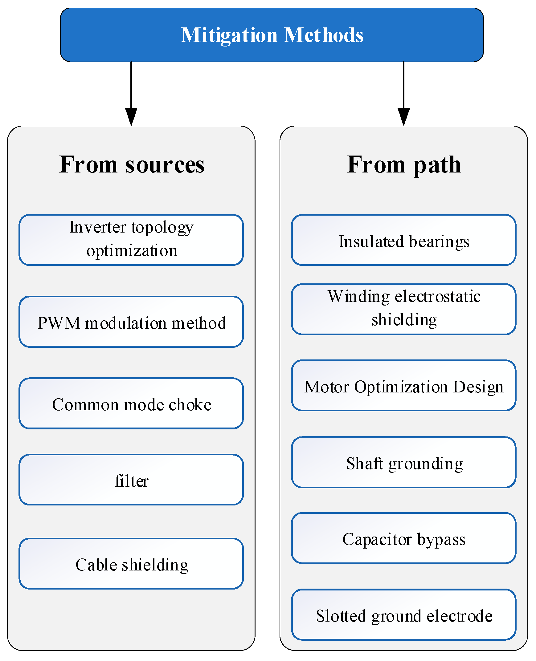
The existence of motor bearing current seriously affects the service life of the motor. In 1907, two German scholars, F. Punga and W. Hess, first proposed that in addition to mechanical reasons, electrical reasons are also factors that cannot be ignored in motor bearing damage. When the shaft voltage of the motor causes the insulation performance of the bearing insulation oil film to fail, the insulation oil film is no longer insulated and conducts, generating bearing current between the inside and outside of the bearing [57]. Figure 11 systematically summarizes the bearing current suppression methods.
At present, the research on bearing current suppression can be divided into two directions [58,59], direct bearing current suppression and indirect bearing current suppression. Direct bearing current suppression mainly suppresses the common-mode voltage output by the inverter. By suppressing the common-mode voltage, the possibility of bearing current generation is reduced to improve the reliability of the bearing, such as optimizing the modulation method of the inverter and improving the inverter topology [60]. Indirect bearing current suppression mainly cuts off the flow path of the bearing current to limit the impact of the bearing current on the life of the bearing, such as adding an active filter to the transmission path, increasing the bypass to lead the bearing current, etc. [61].

3.3.1. Solution to Suppress Bearing Current from the Inverter Side

At the inverter side, there are two major methods for bearing current reduction. One is the optimization of the inverter topology; another is the optimization of the inverter modulation method, or their combination. On the optimization of the inverter topology, reference [62] eliminates the common-mode voltage to ground generated by the inverter modulation by adding one more leg to the typical three-phase inverter. A proper four-phase LC filter is inserted between the inverter and the load to obtain a sinusoidal output line-to-line voltage. In addition, the modulation method is only optimized to make the common-mode voltage zero. Reference [63] proposes a dual-bridge inverter that almost completely eliminates the shaft voltage and bearing current. It works by modulating the common-mode voltage output by the two sets of inverters to opposite polarities, thereby eliminating it. However, it must be used with dual-voltage motors of low voltage levels. Reference [64] concludes that the common-mode voltage, shaft voltage, and bearing current of the three-level inverter are lower than those of the equivalent two-level converter. Reference [65] added a fourth-arm power supply circuit at the neutral point of the three phases of the motor to eliminate the bearing current, and established a 2.5 kW, three-level NPC inverter-powered 3hp induction motor speed control drive system. The results also show that the amplitude of the common-mode voltage can be effectively reduced. The fourth arm consists of eight identical switches, but this method cannot completely eliminate the common-mode voltage generated by the inverter. Another topology optimization method is to add additional circuit elements to the DC link part so that the switching process of the inverter can be carried out at zero-voltage switching (ZVS) or near-zero voltage, thereby greatly reducing switching losses and common-mode voltage [66]. This is also one of the most common methods in industry. In a word, the optimization of the inverter topology includes adding the fourth arm or dual inverter to offset the common-mode voltage of opposite polarity, cascading multi-level inverters to reduce dv/dt, and adding auxiliary circuits in the DC bus to reduce the common-mode voltage amplitude. However, the biggest disadvantage of this method of topology optimization is to increase the cost. Therefore, more attention has been paid to suppressing the common-mode voltage by means of modulation. Comparisons between these two methods are shown in Table 2. The method for suppressing bearing current by modulation will be described in detail in the next section.

3.3.2. Solutions for Suppressing Bearing Currents from Transmission Cables

Among others, the mitigation methods applied to the connection between the motor and its associated inverter are passive/active filters, common mode inductors, and shielded cables. Passive filters usually consist of the component resistor, capacitor, and inductor. These filters serve to damp high-frequency noise or transients (dv/dt) at the motor terminals so as not to damage or cause interference to the motor performance. Their main function is to smooth the voltage waveform and decrease the rate of change in voltage (dv/dt) at the motor terminals so as to decrease the possibility of generating unnecessary currents (like common mode currents) [67,68]. Sine filters are designed to smooth the voltage waveform in order to make it close to a pure sine wave, reducing high-frequency harmonics, preventing sharp voltage changes dv/dt, and further reducing possible bearing currents. The reactors can be connected in series with the motor for the purpose of limiting the high-frequency voltage spikes. By reducing the amplitude of voltage changes, they reduce the severity of potentially harmful currents. Reference [69] uses passive filters to reduce the ground current and circulating current by 30–50%, and experimental results have also confirmed this. However, passive filters cannot eliminate common-mode voltages, but only reduce the influence of common-mode voltages on the system. Therefore, EDM currents are basically unaffected. Passive filters are usually large and expensive due to the size and weight of passive components.
Active filters primarily work by injecting a reverse signal to kill the noise, hence actively reducing common-mode noise. In [70], the authors propose equipping an induction motor of 5 horsepower with a real-time-controllable active filter. It generates an anti-phase signal to offset common-mode noise, hence reducing motor shaft voltage and bearing current. It can effectively reduce the conducted EMI, shaft voltage, and bearing current. Hence, in some applications, especially the control of noise and interference, it is effective compared to passive filters.
The common-mode inductor can suppress the common-mode current flowing from the motor and to the inverter, with its direction on each conductor in a similar mode. Common-mode inductors are normally set up on the inverter output: this allows for the common-mode current inductive impedance, in order not to flow freely, thereby minimizing circulating currents or the currents between rotor groundings. However, common-mode inductors do not affect the common-mode voltage [71]; hence, they hardly have any impact on the motor drive current—the EDM current.
Shielded cables contain an extra conductive layer for grounding to avoid external electromagnetic interference and to reduce the noise emitted by the cable. Shielded cables provide a path to ground for common-mode voltage or noise, which reduces the ground impedance between stator and ground [72]. By reducing this impedance, shielded cables can reduce rotor ground current. Shielded cables can reduce rotor ground current, thereby helping to slow bearing currents. They also have a downside: they may increase stator ground current, leading to an increase in circulating bearing currents. Note that shielded cables have no effect on motor EDM currents. A comparison of different types of bearing current suppression is shown in Table 3.

3.3.3. Solutions to Suppress Bearing Current from the Motor Side

From the motor side, the mitigation method mainly includes the insulation of the bearing, the optimization of the motor itself, and winding electrostatic shielding. The insulation bearing can insert additional resistance and capacitance into the bearing current path, using a polymer sleeve or an aluminum oxide layer on the outer ring. It is a method used in common suppression and mainly applied to low-power and small motors due to costs. The suppression effect of this method has been experimentally verified in references [27,30], and it has a large suppression effect on all forms of bearing current.
In the optimal design of the motor, reference [73] proposes one grounding electrode method by inserting a grounding wire into the stator slot opening to decrease the parasitic capacitance coupling between the rotor and the stator winding to decrease the bearing current. This method analyzes by numerical analysis the influence of electrode displacement on bearing current mitigation performance and provides valuable suggestions for optimizing electrode position in an open slot motor configuration. On this basis, a study in [74] discussed the effect of using grounding electrodes in stator slots to reduce bearing current using the finite element method. In the given paper, bearing voltage under variable electrode diameter is analyzed. The results of it show the experimental process; furthermore, it concluded that the grounding electrodes effectively reduced the voltage bearing of the electrically excited motor bearing. Reference [75] presented the new Zig-Zag stator slot opening geometry to help the motor in lower winding and rotor capacitances. The ratio of bearing currents due to common-mode voltage bearings is reduced, therefore minimizing EDM bearing currents. An improved analytical model is used for the calculation of winding and rotor capacitance with different geometries of slot opening, after which, using the electrostatic and electromagnetic finite element analysis, motors with Zig-Zag slot opening, skewed slot, and classic slot opening topologies were compared. The results point out that the Zig-Zag slot opening is the best for reducing the bearing voltage ratio when torque performance is to be kept close to the original motor. The same reference [76] made a proposal of a method for reduction in the bearing current by modifications of stator winding and slot geometry in the motor. By using finite element modeling and experimental verification, the paper proved the change in stator winding and magnetic circuit geometry to be effective for reduced EDM bearing current for various designs of the motor. To reduce the EDM bearing current, equivalent optimizations of the motor body are performed to decrease the capacitance between the winding and rotor. However, this method has certain limitations. It is not clear whether this method should be employed in different types of motors at different working conditions, which becomes an important problem, and this has not been solved yet.
In [14], an electrostatically shielded induction motor was proposed. The proposed motor reduces the shaft voltage below the breakdown threshold of bearing lubricant. By inserting a Farady shield in the air gap, electric field coupling between stator and rotor can be attenuated, suppressing the bearing current. Reference [77] studied the effectiveness of different shielding designs to reduce parasitic capacitance and associated eddy current losses. The paper discusses various shielding designs for the stator and end winding parts of the motor, and based on the finite element analysis results, motor prototypes with slotted shielding and cantilever shielding are manufactured. These will confirm that the slotted shielding does indeed have an effect, and that the winding–rotor capacitance of the motor can be reduced by about 84%.
However, for different types of bearing currents, the suppression methods are often different. In addition, the literature [32] points out that for low-power motors, the main component of the bearing current is EDM current, while for high-power motors, the main component of the bearing current is the HF circulating shaft current.
For EDM current, it is usually suppressed by setting a bypass, for example, installing a grounding carbon brush on the rotor shaft to introduce the current to the grounding point of the stator housing without passing through the bearing, but this method has certain limitations. The presence of the grounding carbon brush reduces the stability of the system; in the literature [78], the bearing current loop is cut off by setting a grounding electrode at the stator slot. In addition, the EDM current can also be suppressed from the source. Since the EDM current is mainly caused by the common-mode voltage, the EDM current can be suppressed by inserting a common mode filter between the inverter and the motor [79].
An HF circulating shaft current can be suppressed by insulating the bearing on at least one side, mainly to increase the impedance on the circulation path [27]. In addition, ceramic bearings and hybrid bearings can suppress both types of bearing currents, but their cost is relatively high. Although soft-switching inverters are considered an improvement to hard-switching, the experimental results show that their performance on bearing current and shaft voltage issues is not better than that of hard-switching inverters [80]. Table 4 summarizes the current research on bearing current suppression.

3.4. Prediction of Bearing Currents

In previous studies, the impact of bearing current on bearings and the chemical changes inside bearings have been well described [88,89]. However, what still needs to be determined is the critical value of irreversible bearing damage, because the determination and prediction of these critical values are closely related to how long the bearing can maintain its service life [90]. In the previous section, we learned that there are various measures to suppress bearing current. However, in taking the best measures at the right location, only through accurate bearing prediction can we use corresponding bearing current suppression countermeasures.
At present, there are many studies on bearing life prediction [91]. Vibration monitoring is one of the most commonly used methods of detecting bearing damage caused by circulating current [92]. However, there is a certain difficulty in extracting mechanical vibration signals. To address this problem, low-frequency mechanical vibration can be associated with stator current signals, and bearing faults can be predicted by monitoring stator current without direct contact with the inside of the motor. Reference [93] established a mathematical correlation between bearing vibration frequency and current frequency, and experimentally demonstrated the correlation between vibration and current frequency and the detectability of specific frequency bands in motors with specific bearing defects. However, the situation in the article is relatively idealized. The article only experiments on bearing faults (such as outer ring drilling). Under the action of PWM inverters, the actual bearing damage may be more complicated.
The literature [94] first proposed an algorithm to improve bearing life prediction by tracking bearing current discharge events. The real electrical stress was simulated by high-frequency pulse voltage, and the correlation between EDM current and bearing vibration was verified. The bearing EMD current was used as a trigger point to start the bearing life prediction, avoiding the problem of inaccurate prediction in the early stage of traditional methods.
With the increase in data volume and the development of artificial intelligence, deep neural networks applied to motor fault diagnosis research have become increasingly widespread [95,96,97]. In particular, this includes convolutional neural networks (CNNs), recurrent neural networks (RNNs), long short-term memory networks (LSTM), and generative adversarial networks (GANs), which have been widely considered. In [98,99], the CNN networks were used for motor bearing detection. Compared to the above-mentioned machine learning methods, one of the salient features of this approach is that it requires huge amounts of training data in order to improve the model performance. In addition, in [100], Sabir et al. adopted an LSTM-a representative RNN for processing time series for extracting fault features from current signals. Then, the wavelet packet analysis was applied to the filtered signal to extract eight features in time and time–frequency domains after filtering out the redundant frequencies in the signal. The features were combined with an LSTM network and some mature deep learning algorithms for classifying bearing faults with an accuracy rate of over 96%. Figure 12 is a flow chart of a method for predicting bearing failures by means of artificial intelligence.

4. Common-Mode Voltage Suppression Scheme

4.1. Mathematical Model of Common-Mode Voltage of Three-Phase Motor

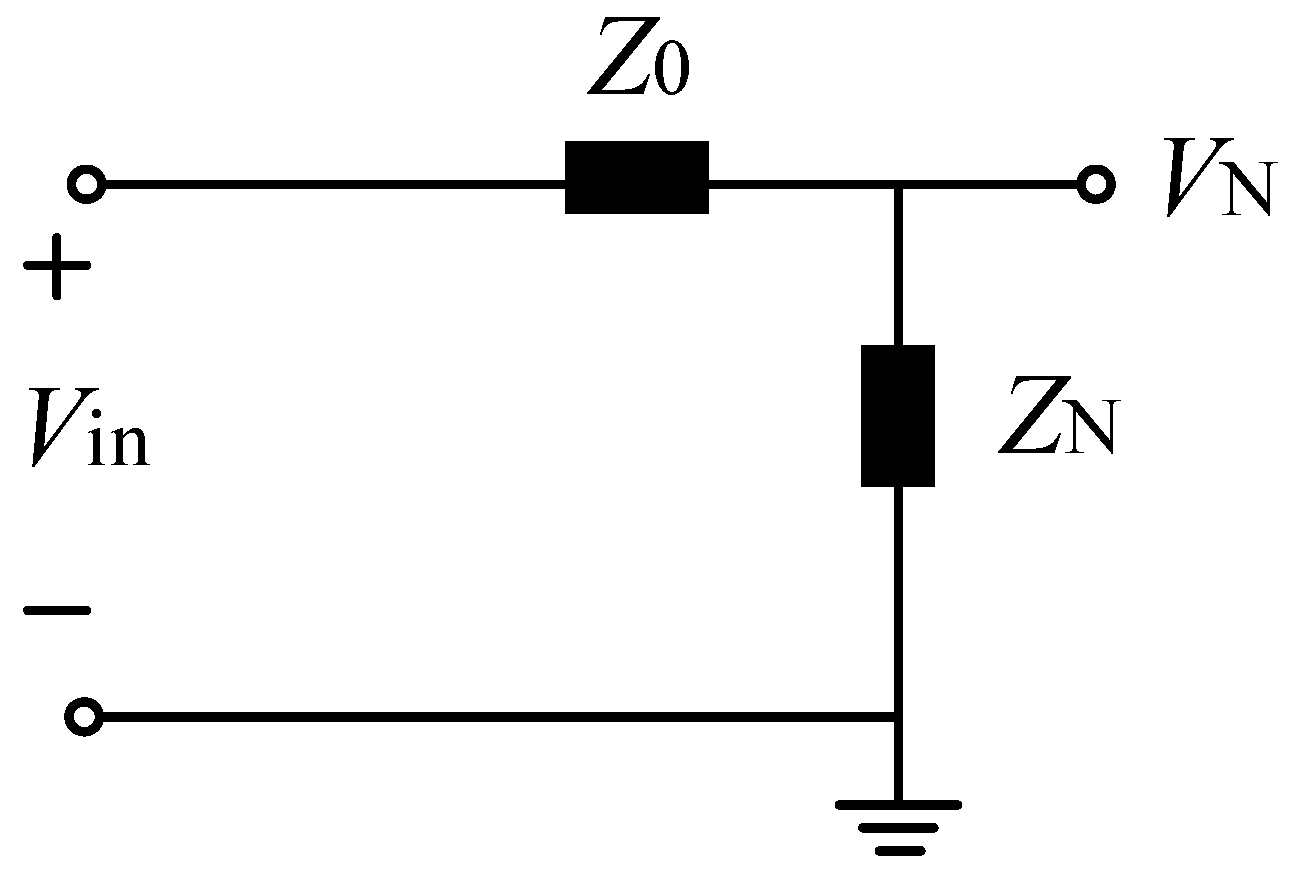
High dv/dt common-mode voltage excitation and coupling capacitance are believed to be the causes of these bearing currents [101]. In the literature [30], the common-mode equivalent circuit of the three-phase inverter is derived in detail, as shown in Figure 13, where Z0 represents the zero-sequence impedance in the load (winding), ZN represents the impedance of the neutral point of the three-phase winding to the ground, and Vin = (VA + VB + VC)/3, where VA, VB, and VC represent each phase voltage relative to the negative DC bus.
The suppression or elimination of common-mode voltage can be achieved through modulation strategies [101]. In general, the common-mode voltage of three-phase motors is suppressed by some modulation methods, including space vector pulse width modulation (SVPWM) technology, carrier base pulse width modulation (CBPWM) technology, and specific harmonic elimination pulse width modulation (SHEPWM) technology.
The principle of SHEPWM is mainly to eliminate the specific harmonics by controlling the switch action at a specific time. Reference [102] adopted the traditional SHEPWM method to eliminate the fifth and seventh harmonics, that is, 6k ± 1st harmonics. In the paper, a three-level inverter is the research object. Experimental results proved that the amplitude of the common-mode voltage will reach a maximum value of Vdc/3, but the paper suppressed the common-mode voltage further by eliminating the 4k ± 1st harmonic, and the value of common-mode voltage will become Vdc/6. The principle of SHEPWM is found from reference [103]. However, this modulation method is not applicable in engineering because it will increase the loss of the switch, and its calculation amount is large. In addition, eliminating the third harmonic will reduce the utilization rate of the motor bus voltage, and the regulation self-use is low. Therefore, SHEPWM is mainly suitable for low-frequency and large-capacity occasions. The two modulation methods commonly used in engineering are SVPWM and CBPWM.

4.1.1. Common-Mode Voltage Suppression Based on SVPWM

For SVPWM technology, the main steps of the algorithm can be divided into three parts: choosing the switch combination state according to the target voltage vector, calculating the action time of every switch state for synthesizing the voltage vector, and designing the proper switch sequence for distributing the switch state’s acting time. For this reason, suppressing the common-mode voltage through SVPWM technology can be studied deeply from these three perspectives.
For the selection of the switching state, two opposite voltage vectors can be used instead of the zero vector, thereby reducing the peak value of the common-mode voltage from ±Udc/2 to ±Udc/6. Several common methods include active zero-state PWM (AZS-PWM) [104,105], remote PWM (RS-PWM), and near-state PWM (NS-PWM).
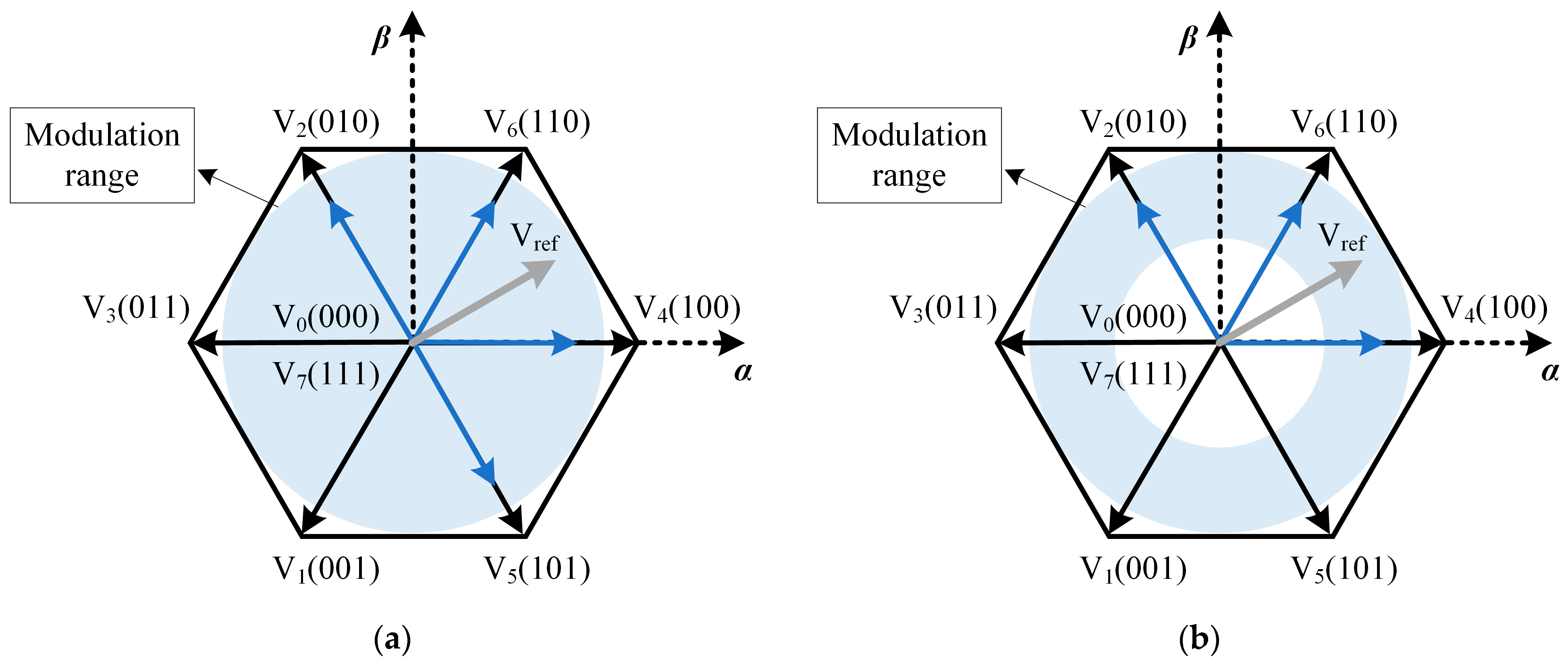
Active zero-state PWM (AZS-PWM): This method calculates the duty cycle of the non-zero-voltage vector based on the volt–second balance law. By selecting two non-zero-voltage vectors in the triangular area where the reference voltage vector is located, and two opposite non-zero-voltage vectors in the adjacent area to participate in the modulation instead of the zero vector, the peak value of the common-mode voltage can be reduced, as shown in Figure 14a. AZS-PWM can be divided into three types: AZS-PWM1, AZS-PWM2, and AZS-PWM3 [106]. The difference lies in the type of opposite vector selected. The linear modulation range of the AZS-PWM method is the same as that of traditional SVPWM, but due to the large number of switching times, the DC bus capacitor voltage ripple may increase and the total harmonic distortion (THD) of the output current may increase.
Near-state PWM (NS-PWM): The fundamental plane is divided into six sectors, and the three vectors closest to Vref are used in each sector to synthesize the target voltage vector, as shown in Figure 14b, thereby avoiding the use of zero vectors and further reducing the common-mode voltage to ±Udc/6 [107]. In addition, since there is always one phase in each sector whose switching state remains unchanged, the switching loss is also effectively reduced. However, the modulation range of NS-PWM is relatively narrow, so it needs to be combined with other modulation methods to meet a wider range of application requirements [108,109]. Remote state PWM (RS-PWM) is a special case of NS-PWM. By dividing the fundamental plane into three sectors and using only even vectors (such as V2, V4, V6) or odd vectors (such as V1, V3, V5) to synthesize the desired voltage vector, the use of zero vectors is avoided. This method can reduce the common-mode voltage peak to ±Udc/6 [110,111]. However, the use of only even or odd vectors causes the switching between sectors to increase the number of switching times, thereby increasing the switching loss and reducing the output current quality, resulting in an increase in total harmonic distortion (THD). In addition, the linear modulation degree of this method is low, which limits its application.
For voltage vector synthesis, by selecting a specific switching state to reduce the common-mode voltage, although the amplitude of the common-mode voltage can be reduced, as the number of switching states decreases in a fundamental cycle, this will also lead to problems such as an increase in current THD. Reducing the common-mode voltage by synthesizing virtual voltage vectors can solve this problem effectively. Reference [112] synthesizes the voltages of adjacent voltage vectors of a three-phase inverter in pairs, and finally reduces the common-mode voltage amplitude to Vdc/6, while eliminating the common-mode voltage spike caused by the dead zone effect, and reducing the output current ripple and THD value. However, the addition of virtual vectors makes the calculation of the trigger time of the switching device more complicated, requiring an additional modulator or a lookup table to obtain the trigger pulse signal of each switch tube, and the requirements for controller performance are also higher.
For the optimization of the action time, for the seven-segment SVPWM, there are two zero-voltage vectors in a fundamental cycle. Since the common-mode voltage corresponding to the zero-voltage vector is the largest, the action time of the zero-voltage vector can be adjusted to reduce the common-mode voltage while keeping the total action time of the zero-voltage vector unchanged [113]. This method is mainly applicable to back-to-back systems, in which the common-mode voltage can be expressed as the difference between the common-mode voltage on the rectifier side and the common-mode voltage on the inverter side. Reference [114] found in the study of the modulation strategy of the back-to-back two-level converter that is based on the traditional SVPWM method, in a carrier cycle, when the switch state on the rectifier side is (110) and the switch state on the inverter side is (000), the output common-mode voltage level is 2Vdc/3. At this time, by redistributing the action time of the zero vector on the inverter side corresponding to the switch states (000) and (111), the switch state (110) on the rectifier side and the switch state (000) on the inverter side no longer appear at the same time, and the common-mode voltage amplitude can be reduced to Vdc/3. This method is simple in principle and easy to implement.
The common-mode voltage can also be suppressed by optimizing the order of switch action. Reference [115] proposed a zero common-mode voltage SVPWM method for the study of two-level parallel inverters; that is, the action order of the two groups of inverters is designed so that the switching states of inverter 1 and inverter 2 at each moment correspond to two adjacent switching states in the two-level space state vector diagram, and the switching states of the two inverters are switched at the same time, and finally the common-mode voltage of the parallel inverter system is suppressed to 0. However, this algorithm will cause the switching sequence to no longer be centrally symmetrical within a fundamental wave cycle, which will increase the current harmonics. In order to have a more intuitive understanding of various suppression methods, various methods are summarized, as shown in Table 5.

4.1.2. Common-Mode Voltage Suppression Based on CBPWM

CBPWM technology is a modulation method commonly used in engineering. Its principle is to obtain the rising or falling edge of the switching signal by directly comparing the carrier (triangular wave) with the modulation wave (sine wave), thereby obtaining a sequence of switching pulses [116]. Therefore, the common-mode voltage suppression method based on CBPWM can be optimized in two dimensions, including carrier optimization and modulation wave optimization, which are discussed in detail below.
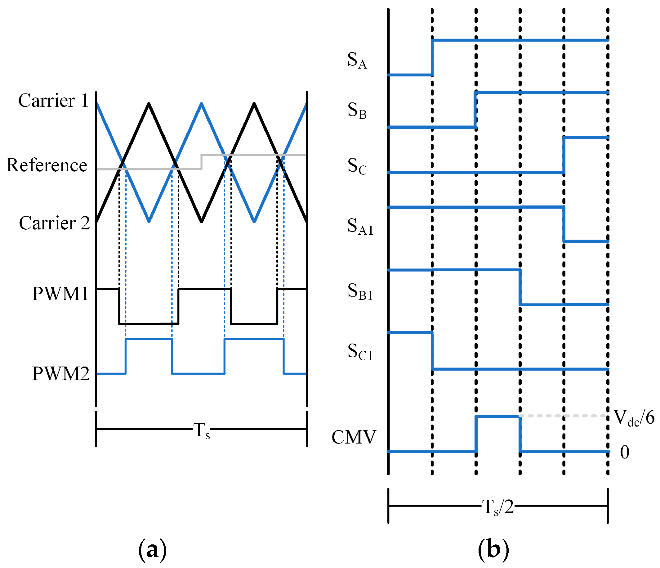
Based on carrier optimization, adjusting the trigger time of the switching pulse by carrier phase shifting is a common optimization method. It is mainly used in multi-level inverters, parallel inverters, and back-to-back inverters. Taking the parallel inverter as an example, the principle is to make the carriers of the two inverters differ by a certain phase angle, so that the switch trigger time of each phase is changed, and the voltage of each phase can offset each other at certain moments to reduce the common-mode voltage. Reference [117] reduces the amplitude of the common-mode voltage to Vdc/6 by carrier phase shifting for parallel inverters. The specific principle is shown in Figure 15. By changing the switching pulse sequence by shifting the carriers of the two inverters by 180°, the common-mode voltage within a fundamental wave cycle can be effectively reduced. However, the main problem with this optimization method is that the common-mode voltage cannot be completely eliminated. There are more carrier optimization methods, such as changing the direction of the carrier, the angle of the carrier, and the peak position of the carrier to achieve the purpose of suppressing the common-mode voltage, and the basic principles are the same.
Based on the optimization of the modulation wave, the most common and most commonly used method in engineering is to suppress the common-mode voltage by zero-sequence voltage injection. The basic principle of zero-sequence voltage injection is to control the balance of the midpoint potential by superimposing the zero-sequence component in the modulation wave. In a three-level inverter, the imbalance of the midpoint potential will lead to problems such as capacitor unequal pressure, output voltage distortion, and low-order harmonics. In order to solve these problems, the zero-sequence component can be injected during the modulation process, and the amount of charge flowing into the midpoint can be controlled by adjusting the value of the zero-sequence component, thereby maintaining the balance of the midpoint potential [118,119]. This carrier modulation method based on zero-sequence voltage injection is essentially the same as the method of adjusting the action time of the zero vector in the SVPWM method. Reference [120] provides a method for reducing the common-mode voltage of two-level and multi-level inverters through this modulation method. That is, the duty cycle of the switching device is adjusted by zero-sequence voltage injection to reduce the amplitude of the common-mode voltage.
In addition, reference [121] proposes a dual-modulation wave carrier pulse width modulation method based on the design idea of the space vector modulation method. Its principle is similar to the principle of vector synthesis in SVPWM, mainly to make the original modulation wave equivalent through the combination of two modulation waves. For the three-level inverter, the paper reverses the polarity of the output voltage of any phase, which can effectively reduce the amplitude of the common-mode voltage, thereby reducing the common-mode voltage amplitude of the three-level inverter to Vdc/6. In short, the common-mode voltage can be effectively reduced by optimizing the modulation wave, but the influence of the common-mode voltage cannot be completely eliminated, and the high dv/dt characteristics of the common-mode voltage cannot be reduced. Table 6 summarizes the common-mode voltage suppression methods based on CBPWM.
In summary, these methods suppress the common-mode voltage in different ways to improve the efficiency and performance of the motor drive system, but in practical applications, factors such as switching loss, output current quality, and modulation range need to be considered [122,123]. However, the values of the common-mode voltage corresponding to various switching states of the three-phase inverter are shown in Table 7. It can be seen that no matter what modulation method is used, the value of the common-mode voltage cannot be maintained at 0. Therefore, no matter what the switching state of the three-phase inverter is, there is always an input excitation source in the common-mode equivalent circuit. Therefore, for the motor powered by the three-phase inverter, the common-mode input cannot be suppressed by changing the modulation strategy.

4.2. Multi-Phase Motor Common-Mode Voltage Prediction of Bearing Currents

Compared with the traditional three-phase motor, the multi-phase motor has more advantages in common-mode voltage suppression and is highly self-used in modulation. For example, the six-phase motor, with a difference of 30° between two-phase windings, has 64 switch combination states for the inverter. Hereby, for the simplification of the mathematical model, the six-phase motor voltage, current, and other vectors are decomposed on three mutually orthogonal subspaces according to Vector Space Decomposition (VSD) [124,125,126]: the fundamental component, and h = 12k ± 1 (k = 1,2,3.) subharmonic components—the αβ subplane; h = 12k ± 5 (k = 0,1,2,3.) subharmonic components (like the 5th and 7th harmonics)—the xy subplane; and h = 3k (k = 1,2,3.) subharmonic components, including the 3rd, 6th, and 9th harmonics, etc. Only the components of the αβ subplane are relevant to the energy conversion of the motor [127,128,129].
They correspond to 64 voltage vectors, including 4 zero vectors, in the αβ subspace and xy subplane, as shown in Figure 16. They are numbered according to the octal number corresponding to the switching state of each phase. For instance, the switching state “111000” is numbered 70, and z = 0 and 7 in Figure 16. Because multi-phase motors enjoy a high degree of freedom in modulation, the six-phase motor can suppress the common-mode voltage by designing the modulation method. The common-mode voltage Vcom of the dual three-phase inverter is given by (Va + Vb + Vc + Vu + Vv + Vw)/6 [130,131,132]. Therefore, the common-mode voltage values related to these 64 voltage vectors can be calculated based on the common-mode voltage formula, as expressed in Table 8.
As can be seen from Table 8, compared with the three-phase inverter, the dual three-phase inverter has a higher degree of freedom in the modulation mode. Therefore, the generation of common-mode voltage can be better suppressed by optimizing the modulation mode.
At present, some research has been performed on the common-mode voltage suppression of six-phase motors by designing modulation methods. Reference [133] proposed a modulation method based on carrier phase-shift pulse width modulation PS-SPWM, which modified the traditional sinusoidal PWM by introducing phase shift to the triangular carrier signal of each phase. The following pertains to phase-shifted carrier waveforms of adjacent phases in an m-phase inverter: The carrier waveform of each phase is shifted by 1/m switching period, with regard to the carrier waveform of the adjacent phase. This kind of approach will reduce the overlapping effect of CMV, since the switching events are dispersed in time. Nevertheless, due to the phase-shifted switching mode, the harmonic distortion of the phase current may be increased. On this basis, one study [134] proposed a sawtooth carrier sinusoidal pulse width modulation (SC-SPWM), which effectively suppressed the common-mode voltage (CMV) by adopting a sawtooth carrier and introducing mirror symmetry in the two sets of three-phase windings of the multi-phase motor. The core principle is to use the asymmetric characteristics of the sawtooth carrier and the symmetrical modulation method of the winding current to make the common-mode voltage between different windings partially offset each other, thereby reducing the amplitude of CMV. The results show that the CMV amplitude can be reduced by 66.67%. However, the hardware implementation is relatively complex. In the literature [135], by selecting and optimizing a special vector combination, the harmonic components of the common-mode voltage are offset in the xy plane, which reduces the total common-mode voltage. The experimental results indicate that this modulation method can reduce the total common-mode voltage in the dual three-phase system effectively. The common-mode voltage of the two sets of three-phase windings can be reduced to one-third of the original value, and hence, the bearing current impact on the system can be reduced. In order to make the common-mode voltage zero, the authors [136] proposed a zero common-mode voltage (ZCMV) modulation strategy for an asymmetric six-phase permanent magnet synchronous motor. This method aims at common-mode voltage elimination by employing a dual two-level inverter and a particular PWM signal modulation strategy. The design of the modulation signal guarantees that the total common-mode voltage mean value in each switching cycle is zero. The rising and falling edges of the PWM signal are aligned in each switching cycle, thereby eliminating the CMV pulse and reducing the electromagnetic interference and bearing current inducted by CMV. Although this method reduces the average value of the total common-mode voltage, it can still have transient common-mode voltage pulses, and this may have some definite impact on the long-run operation of sensitive equipment or motors.
In brief, it can be perceived that the multi-phase motor system possesses a higher degree of freedom in the modulation method. Therefore, optimizing the inverter modulation method allows us to suppress the common-mode voltage, and as a result, the bearing current can be suppressed.

5. Discussions

In this paper, a review of the causes of bearing current and various methods of mitigation were discussed, and the pros and cons of various mitigation methods were analyzed and compared, indicating that the mitigation of bearing current by modulation has great practical value in engineering; it can effectively reduce bearing current and thereby reduce the motor cost. This article finally points out the application of multi-phase motors in modulation technology and its advantages: particularly, in comparison with three-phase motors, the six-phase motor has more phases, and obvious advantages on suppressing harmonic distortion and improving system fault tolerance can be reflected, thus enhancing stability. Due to modulation, it is expected to have high dv/dt for traditional three-phase motors, while, for multi-phase motors, with more balanced phase-to-phase current and voltage waveforms, such problems can be drastically mitigated. It gives even more flexibility for the modulation strategy at the inverter side using multi-phase motors, but it can also easily ensure the complete suppression of common-mode voltage with a modulation method, for instance, modulating zero with the common-mode voltage vector of voltage.
Multi-phase motors have some evident modulation advantages, especially in common-mode voltages and bearing currents, compared with the existing three-phase motor systems. The multi-phase motor can improve not only the operating efficiency of the system by reasonable design and control strategies, but can also reduce the current damage to the bearings effectively and extend the service life of the motor. However, except for the aforementioned obvious advantages of multi-phase motors, current research has been focused mainly on theoretical analysis and experimental verification; how to exploit such advantages fully, in particular under circumstances that require high power density with high dynamic performance, has yet to be determined. At the technical level, some gaps still remain.
The future direction of research is to optimize modulation strategies for multi-phase motors working in complex load and variable operating conditions, especially investigating how new topologies and algorithms can be implemented to further enable efficient energy conversion with low losses. In the future, with the development of power electronic devices and control technology, multi-phase motors will be integrated with intelligent control systems, high-precision sensors, and real-time monitoring technologies to contribute to the intelligent motor drive system. Therefore, these technical improvements can ensure that multi-phase motors will have wider applications in new energy automobiles, industrial robots, high-end manufacturing equipment, and other areas in the near future.
In summary, most of the current research on bearing current is conducted around three-phase motors. However, multi-phase motors have the following advantages over three-phase motors: first, the degree of freedom in the modulation of multi-phase motors is much higher than that of three-phase motors, so it becomes easier to suppress high-frequency common-mode voltage through modulation; secondly, the dv/dt of the voltage output by the multi-phase motor inverter is smaller than that of the three-phase motor, so the bearing current generated is naturally smaller than that of the three-phase motor. Therefore, in terms of bearing current suppression, multi-phase motors have a natural advantage over three-phase motors. In addition, artificial intelligence has proven its practical value, but huge challenges remain. These challenges are focused on three major aspects: training, the acquisition of data, and implementation. The main problems in training relate to the insufficiency and lack of data diversity. The operating environments and conditions of motor systems differ greatly, which makes it challenging to acquire representative and diverse training data in real environments. It specifically leads to poorly simulated motor failure modes, hence a scarcity in training data.

6. Conclusions

In summary, the bearing current phenomenon can seriously damage the motor, and it has great influence on bearing life. Therefore, the study of bearing current suppression has always been a popular issue. This paper introduces, in detail, the mechanism of bearing current generation and the mathematical equivalent model, which pointed out that the high-frequency common-mode voltage generated by the inverter is the main cause of bearing current. Finally, this paper makes a comprehensive comparison of the current research on bearing current suppression methods and the shortcomings of current research. In view of the shortcomings mentioned above, future research directions can focus on the following three directions:
Modulation method research of multi-phase motor systems: For multi-phase motor systems, their advantages in such high power density and high reliability applications slowly increase; related research on modulation methods has become highly popular in recent years. The current modulation method of multi-phase motor systems has achieved some research results, such as how to optimize the modulation strategy to reduce the common-mode voltage and improve the quality of the output waveform. However, the improvement of the modulation method often creates new problems, such as increased current harmonic content, reduced modulation degree, and increased system complexity. These negative sides seriously limit the real potential and application of some modulation methods. Meanwhile, with the number of phases in a multi-phase motor system able to be flexibly adjusted, most of the current research on modulation methods focuses on motors with a certain number of phases, and there is still a lack of a unified theoretical framework and method for researching modulation strategies between motors with different numbers of phases. In this respect, future research should pay more attention to the optimization of multi-phase motor modulation methods. The key point will be finding a solution for the modulation method that allows for current harmonics and reduces efficiency. In addition, the development of one universal modulation strategy for motors with different numbers of phases is another scientific problem that needs to be overcome.
To incorporate this into artificial intelligence technology, along with industrial automation and intelligent development, real-time bearing current monitoring is also a priority to improve equipment operation reliability, promoting the extension of machinery life. In the recent decades, combining artificial intelligence technologies in forecasting bearing current has become an attractive area of research. By introducing such algorithms with artificial intelligence, including machine learning and deep learning, large amounts of operational data will be able to model the bearing currents more precisely in order to forecast in advance the probability of some fault occurring. It can greatly improve the sensitivity and precision of monitoring and reduce traditional dependence on hardware in monitoring. However, most of the current research focuses on the theoretical development of algorithms and verification in laboratory environments, lacking widespread application in complex industrial scenarios. In fact, in engineering, owing to the diversity and complexity of the industrial environment, the inconsistency of data quality, and the robustness of the algorithm, great challenges are still faced.
Improving insulating lubricants in bearings: At present, most high-performance lubricants used on the market depend on traditional chemical synthetic materials, whose production and use may lead to environmental pollution, such as the emission of harmful chemicals or hardly degradable byproducts. This is especially important in large-scale industrial applications, as greater amounts are used, and lubricants are replaced at high rates, meaning their potential to harm the environment cannot be ignored. The pursuit of lubricants made from renewable resources and bio-based materials began in one piece of research, and high-performance electrical insulation is still confronted with great challenges while attempting to keep excellent lubrication performance and environmental friendliness. This is because green lubricants usually have to find balance between chemical stability, lubrication properties, and electrical insulation capability, which involves complex design in the molecular structure of the material.
As for future work, we will concentrate on the following two points: the bearing current effects and new modulation methods of dual three-phase motors. Though some results have been achieved by using the modulation methods developed so far in common-mode voltage reduction, efficiency improvement, and bearing current reduction, large improvement has been made, but most of those methods are basically designed for three-phase motors, so come with certain limitations. As dual three-phase motors are slowly entering the market, future research can be devoted to developing modulation technology for true dual three-phase motors, such as being able to dynamically optimize the modulation strategy according to the real-time working state of the motor to achieve more efficient control with lower losses, and reduce the impact of bearing currents.

Author Contributions

Conceptualization, T.P.; methodology, T.P. and H.Z.; investigation, T.P.; writing—original draft preparation, T.P. and H.Z.; writing—review and editing, H.Z. and W.H.; visualization, W.H. and F.Z.; supervision, W.H. and F.Z. All authors have read and agreed to the published version of the manuscript.

Funding

The National Natural Science Foundation of China, under Grant 52311530085, and the Young Elite Scientists Sponsorship Program by CAST, under Grant 2023QNRC001.

Data Availability Statement

Not applicable.

Acknowledgments

The authors express their gratitude to the National Natural Science Foundation of China.

Conflicts of Interest

The authors declare no conflicts of interest.

References

  1. Hadden, T.; Jiang, J.W.; Bilgin, B.; Yang, Y.; Sathyan, A.; Dadkhah, H.; Emadi, A. A Review of Shaft Voltages and Bearing Currents in EV and HEV Motors. In Proceedings of the IECON 2016—42nd Annual Conference of the IEEE Industrial Electronics Society, Florence, Italy, 23–26 October 2016; pp. 1578–1583. [Google Scholar]
  2. Kudelina, K.; Vaimann, T.; Rassolkin, A.; Kallaste, A.; Asad, B.; Demidova, G. Induction Motor Bearing Currents–Causes and Damages. In Proceedings of the 2021 28th International Workshop on Electric Drives: Improving Reliability of Electric Drives (IWED), Moscow, Russia, 27 January 2021; pp. 1–5. [Google Scholar] [CrossRef]
  3. Liu, R.; Ma, X.; Ren, X.; Cao, J.; Niu, S. Comparative Analysis of Bearing Current in Wind Turbine Generators. Energies 2018, 11, 1305. [Google Scholar] [CrossRef]
  4. Whittle, M.; Trevelyan, J.; Tavner, P.J. Bearing Currents in Wind Turbine Generators. J. Renew. Sustain. Energy 2013, 5, 053128. [Google Scholar] [CrossRef]
  5. de Azevedo, H.D.M.; Araújo, A.M.; Bouchonneau, N. A Review of Wind Turbine Bearing Condition Monitoring: State of the Art and Challenges. Renew. Sustain. Energy Rev. 2016, 56, 368–379. [Google Scholar] [CrossRef]
  6. Bell, R.N.; Mcwilliams, D.W.; O’donnell, P.; Singh, C.; Wells, S.J. Report of Large Motor Reliability Survey of Industrial and Commercial Installations I. IEEE Trans. Ind. Appl. 1985, 21, 853–864. [Google Scholar]
  7. Bell, R.N.; Heising, C.R.; O’donnell, P.; Singh, C.; Wells, S.J. Report of Large Motor Reliability Survey of Industrial and Commercial Installations II. IEEE Trans. Ind. Appl. 1985, 21, 865–872. [Google Scholar]
  8. O’donnell, P.; Heising, C.; Singh, C.; Wells, S.J. Report of Large Motor Reliability Survey of Industrial and Commercial Installations III. IEEE Trans. Ind. Appl. 1987, 23, 153–158. [Google Scholar]
  9. Shami, U.T.; Akagi, H. Experimental Discussions on a Shaft End-to-End Voltage Appearing in an Inverter-Driven Motor. IEEE Trans. Power Electron. 2009, 24, 1532–1540. [Google Scholar] [CrossRef]
  10. Alger, P.L.; Samson, H.W. Shaft Currents in Electric Machines. Trans. Am. Inst. Electr. Eng. 2009, XLIII, 235–245. [Google Scholar] [CrossRef]
  11. IEC 60034-17; Cage Induction Motors When Fed From Converters Application Guide. International Electrotechnical Commission: Geneva, Switzerland, 2007.
  12. NEMA MG-1 Specification 31, Section IV; Motors and Generators. NEMA: Rosslyn, VA, USA, 2021.
  13. Costello, M.J. Shaft Voltages and Rotating Machinery. IEEE Trans. Ind. Appl. 1993, 29, 419–426. [Google Scholar] [CrossRef]
  14. Busse, D.F.; Erdman, J.M.; Kerkman, R.J.; Schlegel, D.W.; Skibinski, G.L. An Evaluation of the Electrostatic Shielded Induction Motor: A Solution for Rotor Shaft Voltage Buildup and Bearing Current. IEEE Trans. Ind. Appl. 1997, 33, 1563–1570. [Google Scholar] [CrossRef]
  15. Xie, G.; Luo, J.; Guo, D.; Liu, S.; Li, G. Damages on the Lubricated Surfaces in Bearings under the Influence of Weak Electrical Currents. Sci. China Technol. Sci. 2013, 56, 2979–2987. [Google Scholar] [CrossRef]
  16. Boyanton, H.E.; Hodges, G. Bearing Fluting [Motors]. IEEE Ind. Appl. Mag. 2002, 8, 53–57. [Google Scholar] [CrossRef]
  17. Nippes, P.I. Early Warning of Developing Problems in Rotating Machinery as Provided by Monitoring Shaft Voltages and Grounding Currents. IEEE Trans. Energy Convers. 2004, 19, 340–345. [Google Scholar] [CrossRef]
  18. Sunahara, K.; Ishida, Y.; Yamashita, S.; Yamamoto, M.; Nishikawa, H.; Matsuda, K.; Kaneta, M. Preliminary Measurements of Electrical Micropitting in Grease-Lubricated Point Contacts. Tribol. Trans. 2011, 54, 730–735. [Google Scholar] [CrossRef]
  19. Robak, S.; Wasilewski, J.; Dawidowski, P.; Szewczyk, M. Variable Speed Drive (VSD)–towards Modern Industry and Electric Power Systems. Rzegląd Elektrotechniczny 2016, 92, 207–210. [Google Scholar] [CrossRef]
  20. McLean, G.W. Review of Recent Progress in Linear Motors. IEE Proc. B (Electr. Power Appl.) 1988, 135, 380–416. [Google Scholar] [CrossRef]
  21. Gieras, J.F.; Piech, Z.J.; Tomczuk, B. Linear Synchronous Motors. In Transportation and Automation Systems; CRC Press: Boca Raton, FL, USA, 2018. [Google Scholar]
  22. Kumar, A.B.; Narayanan, G. Variable-Switching Frequency PWM Technique for Induction Motor Drive to Spread Acoustic Noise Spectrum with Reduced Current Ripple. IEEE Trans. Ind. Appl. 2016, 52, 3927–3938. [Google Scholar] [CrossRef]
  23. Sahu, A.K.; Emadi, A.; Bilgin, B. Noise and Vibration in Switched Reluctance Motors: A Review on Structural Materials, Vibration Dampers, Acoustic Impedance, and Noise Masking Methods. IEEE Access 2023, 11, 27702–27718. [Google Scholar] [CrossRef]
  24. Abad, G.; Rodriguez, M.Á.; Poza, J. Two-Level VSC Based Predictive Direct Torque Control of the Doubly Fed Induction Machine With Reduced Torque and Flux Ripples at Low Constant Switching Frequency. IEEE Trans. Power Electron. 2008, 23, 1050–1061. [Google Scholar] [CrossRef]
  25. Erdman, J.M.; Kerkman, R.J.; Schlegel, D.W.; Skibinski, G.L. Effect of PWM Inverters on AC Motor Bearing Currents and Shaft Voltages. IEEE Trans. Ind. Appl. 1996, 32, 250–259. [Google Scholar] [CrossRef]
  26. Chen, S.; Lipo, T.A. Circulating Type Motor Bearing Current in Inverter Drives. IEEE Ind. Appl. Mag. 1998, 4, 32–38. [Google Scholar] [CrossRef]
  27. Busse, D.; Erdman, J.; Kerkman, R.J.; Schlegel, D.; Skibinski, G. System Electrical Parameters and Their Effects on Bearing Currents. IEEE Trans. Ind. Appl. 1997, 33, 577–584. [Google Scholar] [CrossRef]
  28. Busse, D.; Erdman, J.; Kerkman, R.J.; Schlegel, D.; Skibinski, G. Bearing Currents and Their Relationship to PWM Drives. IEEE Trans. Power Electron. 1997, 12, 243–252. [Google Scholar] [CrossRef]
  29. Guzinski, J. Common-Mode Voltage and Bearing Currents in PWM Inverters: Causes, Effects and Prevention. In Power Electronics for Renewable Energy Systems, Transportation and Industrial Applications; John Wiley & Sons, Ltd.: Hoboken, NJ, USA, 2014; pp. 664–694. ISBN 978-1-118-75552-5. [Google Scholar]
  30. Chen, S.; Lipo, T.A.; Fitzgerald, D. Modeling of Motor Bearing Currents in PWM Inverter Drives. IEEE Trans. Ind. Appl. 1996, 32, 1365–1370. [Google Scholar] [CrossRef]
  31. Chen, S.; Lipo, T.A.; Fitzgerald, D. Source of Induction Motor Bearing Currents Caused by PWM Inverters. IEEE Trans. Energy Convers. 1996, 11, 25–32. [Google Scholar] [CrossRef]
  32. Binder, A.; Muetze, A. Scaling Effects of Inverter-Induced Bearing Currents in AC Machines. IEEE Trans. Ind. Appl. 2008, 44, 769–776. [Google Scholar] [CrossRef]
  33. Collin, R.; Yokochi, A.; von Jouanne, A. Novel Characterization of Si- and SiC-Based PWM Inverter Bearing Currents Using Probability Density Functions. Energies 2022, 15, 3043. [Google Scholar] [CrossRef]
  34. Costabile, G.; De Vivo, B.; Egiziano, L.; Tucci, V.; Vitelli, M.; Beneduce, L.; Iovieno, S.; Masucci, A. An Accurate Evaluation of Electric Discharge Machining Bearings Currents in Inverter-Driven Induction Motors. In Proceedings of the 2007 European Conference on Power Electronics and Applications, Aalborg, Denmark, 2–5 September 2007; pp. 1–8. [Google Scholar]
  35. Quintero, D.R.; Mejia, W.; Rosero, J.A. Good Practice for Electric Discharge Machining (EDM) Bearing Currents Measurement in the Induction Motor and Drives System. In Proceedings of the 2013 International Electric Machines & Drives Conference, Chicago, IL, USA, 12–15 May 2013; pp. 1384–1390. [Google Scholar]
  36. Muetze, A.; Niskanen, V.; Ahola, J. On Radio-Frequency-Based Detection of High-Frequency Circulating Bearing Current Flow. IEEE Trans. Ind. Appl. 2014, 50, 2592–2601. [Google Scholar] [CrossRef]
  37. Magdun, O.; Gemeinder, Y.; Binder, A. Rotor Impedance of the High Frequency Circulating Bearing Current Path in Inverter-Fed AC Machines. In Proceedings of the 2013 IEEE Energy Conversion Congress and Exposition, Denver, CO, USA, 15–19 September 2013; pp. 3512–3519. [Google Scholar]
  38. Jaeger, C.; Grinbaum, I.; Smajic, J. Numerical Simulation and Measurement of Common-Mode and Circulating Bearing Currents. In Proceedings of the 2016 XXII International Conference on Electrical Machines (ICEM), Lausanne, Switzerland, 4–7 September 2016; pp. 486–491. [Google Scholar]
  39. Muetze, A.; Binder, A. Calculation of Circulating Bearing Currents in Machines of Inverter-Based Drive Systems. IEEE Trans. Ind. Electron. 2007, 54, 932–938. [Google Scholar] [CrossRef]
  40. Schuster, M.; Binder, A. Comparison of Different Inverter-Fed AC Motor Types Regarding Common-Mode Bearing Currents. In Proceedings of the 2015 IEEE Energy Conversion Congress and Exposition (ECCE), Montreal, QC, Canada, 20–24 September 2015; pp. 2762–2768. [Google Scholar]
  41. Weicker, M.; Binder, A. Characteristic Parameters for Electrical Bearing Damage. In Proceedings of the 2022 International Symposium on Power Electronics, Electrical Drives, Automation and Motion (SPEEDAM), Sorrento, Italy, 22–24 June 2022; pp. 785–790. [Google Scholar]
  42. Safdarzadeh, O.; Weicker, M.; Binder, A. Measuring of Electrical Currents, Voltage and Resistance of an Axial Bearing. In Proceedings of the 2021 International Aegean Conference on Electrical Machines and Power Electronics (ACEMP) & 2021 International Conference on Optimization of Electrical and Electronic Equipment (OPTIM), Brasov, Romania, 2–3 September 2021; pp. 376–382. [Google Scholar]
  43. Zhu, W.; De Gaetano, D.; Chen, X.; Jewell, G.W.; Hu, Y. A Review of Modeling and Mitigation Techniques for Bearing Currents in Electrical Machines With Variable-Frequency Drives. IEEE Access 2022, 10, 125279–125297. [Google Scholar] [CrossRef]
  44. Muetze, A.; Binder, A. Calculation of Motor Capacitances for Prediction of the Voltage Across the Bearings in Machines of Inverter-Based Drive Systems. IEEE Trans. Ind. Appl. 2007, 43, 665–672. [Google Scholar] [CrossRef]
  45. Han, P.; Heins, G.; Patterson, D.; Thiele, M.; Ionel, D.M. Modeling of Bearing Voltage in Electric Machines Based on Electromagnetic FEA and Measured Bearing Capacitance. IEEE Trans. Ind. Appl. 2021, 57, 4765–4775. [Google Scholar] [CrossRef]
  46. Liu, Y.; Cao, J.; Song, Y.; Xu, G.; Li, L. Research on Bearing Current Detection Method of High-Speed Motor Driven by PWM Inverter. In Proceedings of the 2019 22nd International Conference on Electrical Machines and Systems (ICEMS), Harbin, China, 11–14 August 2019; pp. 1–6. [Google Scholar]
  47. Kindl, V.; Skala, B.; Pechanek, R.; Byrtus, M.; Hruska, K. Calculation of Induction Machine Parasitic Capacitances Using Finite Element Method. In Proceedings of the 2016 ELEKTRO, Strbske Pleso, Slovakia, 16–18 May 2016; pp. 176–179. [Google Scholar]
  48. Jaritz, M.; Jaeger, C.; Bucher, M.; Smajic, J.; Vukovic, D.; Blume, S. An Improved Model for Circulating Bearing Currents in Inverter-Fed AC Machines. In Proceedings of the 2019 IEEE International Conference on Industrial Technology (ICIT), Melbourne, VIC, Australia, 13–15 February 2019; pp. 225–230. [Google Scholar]
  49. Bubert, A.; Zhang, J.; De Doncker, R.W. Modeling and Measurement of Capacitive and Inductive Bearing Current in Electrical Machines. In Proceedings of the 2017 Brazilian Power Electronics Conference (COBEP), Juiz de Fora, Brazil, 19–22 November 2017; pp. 1–6. [Google Scholar]
  50. Li, J.; Liu, R.; Zheng, B.; Zhang, Y. The Effects of End Part of Winding on Parasitic Capacitances of Induction Motor Fed by PWM Inverter. In Proceedings of the 2012 15th International Conference on Electrical Machines and Systems (ICEMS), Sapporo, Japan, 21–24 October 2012; pp. 1–5. [Google Scholar]
  51. Wu, J.; Zhuo, L.; Pei, J.; Li, Y.; Xie, H.; Wu, J.; Liu, H. Modularized and Parametric Modeling Technology for Finite Element Simulations of Underground Engineering under Complicated Geological Conditions. CMES 2024, 140, 621–645. [Google Scholar] [CrossRef]
  52. Kongar-Syuryun, C.; Klyuev, R.; Golik, V.; Oganesyan, A.; Solovykh, D.; Khayrutdinov, M.; Adigamov, D. Principles of Sustainable Development of Georesources as a Way to Reduce Urban Vulnerability. Urban Sci. 2024, 8, 44. [Google Scholar] [CrossRef]
  53. Gonda, A.; Capan, R.; Bechev, D.; Sauer, B. The Influence of Lubricant Conductivity on Bearing Currents in the Case of Rolling Bearing Greases. Lubricants 2019, 7, 108. [Google Scholar] [CrossRef]
  54. Jammoul, S.; Pusca, R.; Romary, R.; Lefevre, G.; Voyer, N.; Mariani, G.B. Analysis of Capacitive Discharges in Motor Bearings under Different Operation Conditions. IET Electr. Power Appl. 2024, 18, 952–961. [Google Scholar] [CrossRef]
  55. Magdun, O.; Binder, A. Calculation of Roller and Ball Bearing Capacitances and Prediction of EDM Currents. In Proceedings of the 2009 35th Annual Conference of IEEE Industrial Electronics, Porto, Portugal, 3–5 November 2009; pp. 1051–1056. [Google Scholar]
  56. Wang, Z.; Mao, S.; Tian, H.; Su, B.; Cui, Y. Simulation Analysis and Experimental Research on Electric Thermal Coupling of Current Bearing. Lubricants 2024, 12, 73. [Google Scholar] [CrossRef]
  57. Punga, F.; Hess, W. Bearing Currents. Elektrotechnik Maschinenbau 1907, 25, 615–618. [Google Scholar]
  58. Im, J.-H.; Kang, J.-K.; Lee, Y.-K.; Hur, J. Shaft Voltage Elimination Method to Reduce Bearing Faults in Dual Three-Phase Motor. IEEE Access 2022, 10, 81042–81053. [Google Scholar] [CrossRef]
  59. Tawfiq, K.B.; Güleç, M.; Sergeant, P. Bearing Current and Shaft Voltage in Electrical Machines: A Comprehensive Research Review. Machines 2023, 11, 550. [Google Scholar] [CrossRef]
  60. He, F.; Xie, G.; Luo, J. Electrical Bearing Failures in Electric Vehicles. Friction 2020, 8, 4–28. [Google Scholar] [CrossRef]
  61. Ma, J.; Xue, Y.; Han, Q.; Li, X.; Yu, C. Motor Bearing Damage Induced by Bearing Current: A Review. Machines 2022, 10, 1167. [Google Scholar] [CrossRef]
  62. Julian, A.L.; Oriti, G.; Lipo, T.A. Elimination of Common-Mode Voltage in Three-Phase Sinusoidal Power Converters. IEEE Trans. Power Electron. 1999, 14, 982–989. [Google Scholar] [CrossRef]
  63. von Jauanne, A.; Zhang, H. A Dual-Bridge Inverter Approach to Eliminating Common-Mode Voltages and Bearing and Leakage Currents. IEEE Trans. Power Electron. 1999, 14, 43–48. [Google Scholar] [CrossRef]
  64. Chandrashekar, S.M.; Ramachandran, A.; Reddy, M.C. Simulation and Experimental Measurement of Shaft Voltage, Bearing Current in Induction Motor Drive. In Proceedings of the 2017 IEEE International Conference on Power, Control, Signals and Instrumentation Engineering (ICPCSI), Chennai, India, 21–22 September 2017; pp. 732–737. [Google Scholar]
  65. Bharatiraja, C.; Selvaraj, R.; Chelliah, T.R.; Munda, J.L.; Tariq, M.; Maswood, A.I. Design and Implementation of Fourth Arm for Elimination of Bearing Current in NPC-MLI-Fed Induction Motor Drive. IEEE Trans. Ind. Appl. 2018, 54, 745–754. [Google Scholar] [CrossRef]
  66. Turzynski, M.; Chrzan, P.J. Reducing Common-Mode Voltage and Bearing Currents in Quasi-Resonant DC-Link Inverter. IEEE Trans. Power Electron. 2020, 35, 9553–9562. [Google Scholar] [CrossRef]
  67. Akagi, H.; Tamura, S. A Passive EMI Filter for Eliminating Both Bearing Current and Ground Leakage Current From an Inverter-Driven Motor. IEEE Trans. Power Electron. 2006, 21, 1459–1469. [Google Scholar] [CrossRef]
  68. Jiang, Y.; Wu, W.; He, Y.; Chung, H.S.-H.; Blaabjerg, F. New Passive Filter Design Method for Overvoltage Suppression and Bearing Currents Mitigation in a Long Cable Based PWM Inverter-Fed Motor Drive System. IEEE Trans. Power Electron. 2017, 32, 7882–7893. [Google Scholar] [CrossRef]
  69. Muetze, A.; Binder, A. Experimental Evaluation of Mitigation Techniques for Bearing Currents in Inverter-Supplied Drive-Systems–Investigations on Induction Motors up to 500 kW. In Proceedings of the IEEE International Electric Machines and Drives Conference, 2003. IEMDC’03, Madison, WI, USA, 1–4 June 2003; Volume 3, pp. 1859–1865. [Google Scholar]
  70. Anagha, E.R.; Nisha, P.V.; Sindhu, T.K. Design of an Active EMI Filter for Bearing Current Elimination in VFD. In Proceedings of the 2018 IEEE International Symposium on Electromagnetic Compatibility and 2018 IEEE Asia-Pacific Symposium on Electromagnetic Compatibility (EMC/APEMC), Singapore, 14–18 May 2018; pp. 131–134. [Google Scholar]
  71. Mechlinski, M.; Schröder, S.; Shen, J.; De Doncker, R.W. Grounding Concept and Common-Mode Filter Design Methodology for Transformerless MV Drives to Prevent Bearing Current Issues. IEEE Trans. Ind. Appl. 2017, 53, 5393–5404. [Google Scholar] [CrossRef]
  72. Bartolucci, E.J.; Finke, B.H. Cable Design for PWM Variable-Speed AC Drives. IEEE Trans. Ind. Appl. 2001, 37, 415–422. [Google Scholar] [CrossRef]
  73. Vostrov, K.; Petrov, I.; Abramenko, V.; Pyrhönen, J. Grounded Electrodes Approach to Reduce Bearing Currents: Robustness Analysis for Open-Slots Machines. In Proceedings of the 2024 IEEE 33rd International Symposium on Industrial Electronics (ISIE), Ulsan, Republic of Korea, 18–21 June 2024; pp. 1–7. [Google Scholar]
  74. Vostrov, K.; Pyrhönen, J.; Niemelä, M.; Lindh, P.; Ahola, J. On the Application of Extended Grounded Slot Electrodes to Reduce Noncirculating Bearing Currents. IEEE Trans. Ind. Electron. 2023, 70, 2286–2295. [Google Scholar] [CrossRef]
  75. De Gaetano, D.; Zhu, W.; Sun, X.; Chen, X.; Griffo, A.; Jewell, G.W. Novel Stator Slot Opening to Reduce Electrical Machine Bearing Currents. IEEE Trans. Magn. 2023, 59, 1–5. [Google Scholar] [CrossRef]
  76. Vostrov, K.; Pyrhönen, J.; Niemelä, M.; Ahola, J.; Lindh, P. Mitigating Noncirculating Bearing Currents by a Correct Stator Magnetic Circuit and Winding Design. IEEE Trans. Ind. Electron. 2021, 68, 3805–3812. [Google Scholar] [CrossRef]
  77. Scheuermann, S.; Brodatzki, M.; Doppelbauer, M. Investigation of Electrostatic Shieldings in Traction Motors to Mitigate Capacitive Bearing Currents. In Proceedings of the 2024 International Symposium on Power Electronics, Electrical Drives, Automation and Motion (SPEEDAM), Napoli, Italy, 19–21 June 2024; pp. 1087–1092. [Google Scholar]
  78. Vostrov, K.; Pyrhönen, J.; Lindh, P.; Niemelä, M.; Ahola, J. Mitigation of Inverter-Induced Noncirculating Bearing Currents by Introducing Grounded Electrodes into Stator Slot Openings. IEEE Trans. Ind. Electron. 2021, 68, 11752–11760. [Google Scholar] [CrossRef]
  79. Yang, M.; Cheng, Y.; Du, B.; Li, Y.; Wang, S.; Cui, S. Research on Analysis and Suppression Methods of the Bearing Current for Electric Vehicle Motor Driven by SiC Inverter. Energies 2024, 17, 1109. [Google Scholar] [CrossRef]
  80. Chen, S.; Lipo, T.A. Bearing Currents and Shaft Voltages of an Induction Motor under Hard- and Soft-Switching Inverter Excitation. IEEE Trans. Ind. Appl. 1998, 34, 1042–1048. [Google Scholar] [CrossRef]
  81. Ludois, D.C.; Reed, J.K. Brushless Mitigation of Bearing Currents in Electric Machines Via Capacitively Coupled Shunting. IEEE Trans. Ind. Appl. 2015, 51, 3783–3790. [Google Scholar] [CrossRef]
  82. Vostrov, K. Reduction of Non-Circulating Bearing Currents by Electrical Machine Design. Ph.D. Thesis, Lappeenranta-Lahti University of Technology LUT, Lappeenranta, Finland, 2023. ISBN 978-952-335-961-1. [Google Scholar]
  83. Sanchez, L.J.; Hager, C.H., Jr.; Evans, R.D. Rolling Element Bearing Damage in the Presence of Applied Electric Current. Tribol. Trans. 2024, 67, 602–613. [Google Scholar] [CrossRef]
  84. Aqil, M.; Im, J.-H.; Hur, J. Application of Perovskite Layer to Rotor for Enhanced Stator-Rotor Capacitance for PMSM Shaft Voltage Reduction. Energies 2020, 13, 5762. [Google Scholar] [CrossRef]
  85. Lee, S.J.; Choi, J.; Lim, G.C.; Kim, S.M.; Kim, E.-K.; Ha, J.-I. Analysis and Mitigation of Bearing Current in Inverter-Fed IPMSMs Drive System. IEEE Trans. Ind. Electron. 2024, 1–11. [Google Scholar] [CrossRef]
  86. Kalaiselvi, J.; Srinivas, S. Bearing Currents and Shaft Voltage Reduction in Dual-Inverter-Fed Open-End Winding Induction Motor With Reduced CMV PWM Methods. IEEE Trans. Ind. Electron. 2015, 62, 144–152. [Google Scholar] [CrossRef]
  87. Cheng, Y.; Yang, M.; Peng, H.; Du, B.; Zhao, T.; Cui, S. Research on Suppression Method of Bearing Current for Electric Vehicle Motor Driven by SiC Inverter. In Proceedings of the IECON 2023—49th Annual Conference of the IEEE Industrial Electronics Society, Singapore, 16–19 October 2023; pp. 1–6. [Google Scholar]
  88. Magdun, O.; Gemeinder, Y.; Binder, A. Investigation of Influence of Bearing Load and Bearing Temperature on EDM Bearing Currents. In Proceedings of the 2010 IEEE Energy Conversion Congress and Exposition, Atlanta, GA, USA, 12–16 September 2010; pp. 2733–2738. [Google Scholar]
  89. Muetze, A.; Tamminen, J.; Ahola, J. Influence of Motor Operating Parameters on Discharge Bearing Current Activity. IEEE Trans. Ind. Appl. 2011, 47, 1767–1777. [Google Scholar] [CrossRef]
  90. Tischmacher, H.; Gattermann, S. Bearing Currents in Converter Operation. In Proceedings of the The XIX International Conference on Electrical Machines–ICEM 2010, Rome, Italy, 6–8 September 2010; pp. 1–8. [Google Scholar]
  91. Immovilli, F.; Bellini, A.; Rubini, R.; Tassoni, C. Diagnosis of Bearing Faults in Induction Machines by Vibration or Current Signals: A Critical Comparison. IEEE Trans. Ind. Appl. 2010, 46, 1350–1359. [Google Scholar] [CrossRef]
  92. Prudhom, A.; Antonino-Daviu, J.; Razik, H.; Climente-Alarcon, V. Time-Frequency Vibration Analysis for the Detection of Motor Damages Caused by Bearing Currents. Mech. Syst. Signal Process. 2017, 84, 747–762. [Google Scholar] [CrossRef]
  93. Schoen, R.R.; Habetler, T.G.; Kamran, F.; Bartfield, R.G. Motor Bearing Damage Detection Using Stator Current Monitoring. IEEE Trans. Ind. Appl. 1995, 31, 1274–1279. [Google Scholar] [CrossRef]
  94. Singleton, R.K.; Strangas, E.G.; Aviyente, S. The Use of Bearing Currents and Vibrations in Lifetime Estimation of Bearings. IEEE Trans. Ind. Inf. 2017, 13, 1301–1309. [Google Scholar] [CrossRef]
  95. Afshar, M.; Rajabioun, R.; Akin, B. Current-Driven Deep Learning for Enhanced Motor Bearing Prognostics. IEEE Trans. Ind. Appl. 2024, 1–10. [Google Scholar] [CrossRef]
  96. Guan, B.; Bao, X.; Qiu, H.; Yang, D. Enhancing Bearing Fault Diagnosis Using Motor Current Signals: A Novel Approach Combining Time Shifting and CausalConvNets. Measurement 2024, 226, 114049. [Google Scholar] [CrossRef]
  97. de Araújo, V.G.; Bissiriou, A.O.-S.; Villanueva, J.M.M.; Villarreal, E.R.L.; Salazar, A.O.; de Teixeira, R.A.; Fonsêca, D.A.d.M. Monitoring and Diagnosing Faults in Induction Motors’ Three-Phase Systems Using NARX Neural Network. Energies 2024, 17, 4609. [Google Scholar] [CrossRef]
  98. Senanayaka, J.S.L.; Kandukuri, S.T.; Khang, H.V.; Robbersmyr, K.G. Early Detection and Classification of Bearing Faults Using Support Vector Machine Algorithm. In Proceedings of the 2017 IEEE Workshop on Electrical Machines Design, Control and Diagnosis (WEMDCD), Nottingham, UK, 20–21 April 2017; pp. 250–255. [Google Scholar]
  99. Roy, S.S.; Dey, S.; Chatterjee, S. Autocorrelation Aided Random Forest Classifier-Based Bearing Fault Detection Framework. IEEE Sens. J. 2020, 20, 10792–10800. [Google Scholar] [CrossRef]
  100. Ozcan, I.H.; Devecioglu, O.C.; Ince, T.; Eren, L.; Askar, M. Enhanced Bearing Fault Detection Using Multichannel, Multilevel 1D CNN Classifier. Electr. Eng. 2022, 104, 435–447. [Google Scholar] [CrossRef]
  101. Liu, Z.; Cheng, X.; Peng, X.; Wang, P.; Zhao, X.; Liu, J.; Jiang, D.; Qu, R. A Review of Common-Mode Voltage Suppression Methods in Wind Power Generation. Renew. Sustain. Energy Rev. 2024, 203, 114773. [Google Scholar] [CrossRef]
  102. Wu, M.; Xue, C.; Li, Y.W.; Yang, K. A Generalized Selective Harmonic Elimination PWM Formulation With Common-Mode Voltage Reduction Ability for Multilevel Converters. IEEE Trans. Power Electron. 2021, 36, 10753–10765. [Google Scholar] [CrossRef]
  103. Patel, H.S.; Hoft, R.G. Generalized Techniques of Harmonic Elimination and Voltage Control in Thyristor Inverters: Part I–Harmonic Elimination. IEEE Trans. Ind. Appl. 1973, IA-9, 310–317. [Google Scholar] [CrossRef]
  104. Yun, S.-W.; Baik, J.-H.; Kim, D.-S.; Yoo, J.-Y. A New Active Zero State PWM Algorithm for Reducing the Number of Switchings. J. Power Electron. 2017, 17, 88–95. [Google Scholar] [CrossRef]
  105. Baik, J.-H.; Yun, S.-W.; Kim, D.-S.; Kwon, C.-K.; Yoo, J.-Y. EMI Noise Reduction with New Active Zero State PWM for Integrated Dynamic Brake Systems. J. Power Electron. 2018, 18, 923–930. [Google Scholar] [CrossRef]
  106. Chen, H.; Zhao, H. Review on Pulse-Width Modulation Strategies for Common-Mode Voltage Reduction in Three-Phase Voltage-Source Inverters. IET Power Electron. 2016, 9, 2611–2620. [Google Scholar] [CrossRef]
  107. Zhang, M.; Atkinson, D.J.; Ji, B.; Armstrong, M.; Ma, M. A Near-State Three-Dimensional Space Vector Modulation for a Three-Phase Four-Leg Voltage Source Inverter. IEEE Trans. Power Electron. 2014, 29, 5715–5726. [Google Scholar] [CrossRef]
  108. Un, E.; Hava, A.M. A Near-State PWM Method With Reduced Switching Losses and Reduced Common-Mode Voltage for Three-Phase Voltage Source Inverters. IEEE Trans. Ind. Appl. 2009, 45, 782–793. [Google Scholar] [CrossRef]
  109. Hava, A.M.; Ün, E. Performance Analysis of Reduced Common-Mode Voltage PWM Methods and Comparison With Standard PWM Methods for Three-Phase Voltage-Source Inverters. IEEE Trans. Power Electron. 2009, 24, 241–252. [Google Scholar] [CrossRef]
  110. Cacciato, M.; Consoli, A.; Scarcella, G.; Testa, A. Reduction of Common-Mode Currents in PWM Inverter Motor Drives. IEEE Trans. Ind. Appl. 1999, 35, 469–476. [Google Scholar] [CrossRef]
  111. Baik, J.; Yun, S.; Kim, D.; Kwon, C.; Yoo, J. Remote-State PWM with Minimum RMS Torque Ripple and Reduced Common-Mode Voltage for Three-Phase VSI-Fed BLAC Motor Drives. Electronics 2020, 9, 586. [Google Scholar] [CrossRef]
  112. Guo, L.; Jin, N.; Gan, C.; Luo, K. Hybrid Voltage Vector Preselection-Based Model Predictive Control for Two-Level Voltage Source Inverters to Reduce the Common-Mode Voltage. IEEE Trans. Ind. Electron. 2020, 67, 4680–4691. [Google Scholar] [CrossRef]
  113. Samanes, J.; Gubia, E.; Juankorena, X.; Girones, C. Common-Mode and Phase-to-Ground Voltage Reduction in Back-to-Back Power Converters With Discontinuous PWM. IEEE Trans. Ind. Electron. 2020, 67, 7499–7508. [Google Scholar] [CrossRef]
  114. Lee, H.-D.; Sul, S.-K. Common Mode Voltage Reduction Method Modifying the Distribution of Zero Voltage Vector in PWM Converter/Inverter System. In Proceedings of the Conference Record of the 1999 IEEE Industry Applications Conference, Thirty-Forth IAS Annual Meeting (Cat. No.99CH36370), Phoenix, AZ, USA, 3–7 October 1999; Volume 3, pp. 1596–1601. [Google Scholar]
  115. Shen, Z.; Jiang, D.; Zou, J.; Liu, Z.; Ma, C. Current-Balance Mode-Based Unified Common-Mode Voltage Elimination Scheme for Dual Three-Phase Motor Drive System. IEEE Trans. Ind. Electron. 2022, 69, 12575–12586. [Google Scholar] [CrossRef]
  116. Kimball, J.W.; Zawodniok, M. Reducing Common-Mode Voltage in Three-Phase Sine-Triangle PWM With Interleaved Carriers. IEEE Trans. Power Electron. 2011, 26, 2229–2236. [Google Scholar] [CrossRef]
  117. Jiang, D.; Shen, Z.; Wang, F. Common-Mode Voltage Reduction for Paralleled Inverters. IEEE Trans. Power Electron. 2018, 33, 3961–3974. [Google Scholar] [CrossRef]
  118. Xiong, W.; Sun, Y.; Su, M.; Zhang, J.; Liu, Y.; Yang, J. Carrier-Based Modulation Strategies With Reduced Common-Mode Voltage for Five-Phase Voltage Source Inverters. IEEE Trans. Power Electron. 2018, 33, 2381–2394. [Google Scholar] [CrossRef]
  119. Nguyen, N.-V.; Doi, M.-V. Carrier Based PWM Control of 3-Level NPC Inverter with DC Neutral Point Balancing and Common Mode Voltage Reduction. In Proceedings of the 2019 10th International Conference on Power Electronics and ECCE Asia (ICPE 2019–ECCE Asia), Busan, Republic of Korea, 27–30 May 2019; pp. 1213–1220. [Google Scholar]
  120. Xu, X.; Zheng, Z.; Wang, K.; Yang, B.; Li, Y. A Comprehensive Study of Common Mode Voltage Reduction and Neutral Point Potential Balance for a Back-to-Back Three-Level NPC Converter. IEEE Trans. Power Electron. 2020, 35, 7910–7920. [Google Scholar] [CrossRef]
  121. Liu, P.; Duan, S.; Yao, C.; Chen, C. A Double Modulation Wave CBPWM Strategy Providing Neutral-Point Voltage Oscillation Elimination and CMV Reduction for Three-Level NPC Inverters. IEEE Trans. Ind. Electron. 2018, 65, 16–26. [Google Scholar] [CrossRef]
  122. Turzyński, M.; Musznicki, P. A Review of Reduction Methods of Impact of Common-Mode Voltage on Electric Drives. Energies 2021, 14, 4003. [Google Scholar] [CrossRef]
  123. Kwak, S.; Mun, S. Model Predictive Control Methods to Reduce Common-Mode Voltage for Three-Phase Voltage Source Inverters. IEEE Trans. Power Electron. 2015, 30, 5019–5035. [Google Scholar] [CrossRef]
  124. Gao, H.; Guo, J.; Hou, Z.; Zhang, B.; Dong, Y. Fault Diagnosis Method of Six-Phase Permanent Magnet Synchronous Motor Based on Vector Space Decoupling. Electronics 2022, 11, 1229. [Google Scholar] [CrossRef]
  125. Zhao, Y.; Lipo, T.A. Space Vector PWM Control of Dual Three-Phase Induction Machine Using Vector Space Decomposition. IEEE Trans. Ind. Appl. 1995, 31, 1100–1109. [Google Scholar] [CrossRef]
  126. Wang, Z.; Wang, Y.; Chen, J.; Hu, Y. Decoupled Vector Space Decomposition Based Space Vector Modulation for Dual Three-Phase Three-Level Motor Drives. IEEE Trans. Power Electron. 2018, 33, 10683–10697. [Google Scholar] [CrossRef]
  127. Marouani, K.; Baghli, L.; Hadiouche, D.; Kheloui, A.; Rezzoug, A. A New PWM Strategy Based on a 24-Sector Vector Space Decomposition for a Six-Phase VSI-Fed Dual Stator Induction Motor. IEEE Trans. Ind. Electron. 2008, 55, 1910–1920. [Google Scholar] [CrossRef]
  128. Grandi, G.; Serra, G.; Tani, A. Space Vector Modulation of a Six-Phase VSI Based on Three-Phase Decomposition. In Proceedings of the Automation and Motion 2008 International Symposium on Power Electronics, Electrical Drives, Ischia, Italy, 11–13 June 2008; pp. 674–679. [Google Scholar]
  129. Abu-Seif, M.A.; Ahmed, M.; Metwly, M.Y.; Abdel-Khalik, A.S.; Hamad, M.S.; Ahmed, S.; Elmalhy, N. Data-Driven-Based Vector Space Decomposition Modeling of Multiphase Induction Machines. IEEE Trans. Energy Convers. 2023, 38, 2061–2074. [Google Scholar] [CrossRef]
  130. Alcaide, A.M.; Wang, X.; Yan, H.; Leon, J.I.; Monopoli, V.G.; Buticchi, G.; Vazquez, S.; Liserre, M.; Franquelo, L.G. Common-Mode Voltage Mitigation of Dual Three-Phase Voltage Source Inverters in a Motor Drive Application. IEEE Access 2021, 9, 67477–67487. [Google Scholar] [CrossRef]
  131. Mansuri, A.; Maurya, R.; Suhel, S.M.; Iqbal, A. Novel SV-PWM Strategies for Six-Phase Induction Motor Drive With Reduced Switching Losses and Common-Mode Voltage. IEEE Trans. Power Electron. 2024, 39, 14–24. [Google Scholar] [CrossRef]
  132. Zhao, L.; Huang, S.; Gao, Y.; Zheng, J. A Common-Mode Voltage Suppression Strategy Based on Double Zero-Sequence Injection PWM for Two-Level Six-Phase VSIs. Energies 2022, 15, 6242. [Google Scholar] [CrossRef]
  133. Liu, Z.; Zheng, Z.; Sudhoff, S.D.; Gu, C.; Li, Y. Reduction of Common-Mode Voltage in Multiphase Two-Level Inverters Using SPWM With Phase-Shifted Carriers. IEEE Trans. Power Electron. 2016, 31, 6631–6645. [Google Scholar] [CrossRef]
  134. Liu, Z.; Zheng, Z.; Peng, Z.; Li, Y.; Hao, L. A Sawtooth Carrier-Based PWM for Asymmetrical Six-Phase Inverters With Improved Common-Mode Voltage Performance. IEEE Trans. Power Electron. 2018, 33, 9444–9458. [Google Scholar] [CrossRef]
  135. Fangke, L.; Haifeng, L.; Yongdong, L.; Jianyun, C. A Modulation Method to Eliminate Common-Mode Voltage of Dual Three-Phase Motor. In Proceedings of the 2019 IEEE Transportation Electrification Conference and Expo (ITEC), Detroit, MI, USA, 19–21 June 2019; pp. 1–5. [Google Scholar]
  136. Shen, Z.; Jiang, D.; Liu, Z.; Ye, D.; Li, J. Common-Mode Voltage Elimination for Dual Two-Level Inverter-Fed Asymmetrical Six-Phase PMSM. IEEE Trans. Power Electron. 2020, 35, 3828–3840. [Google Scholar] [CrossRef]
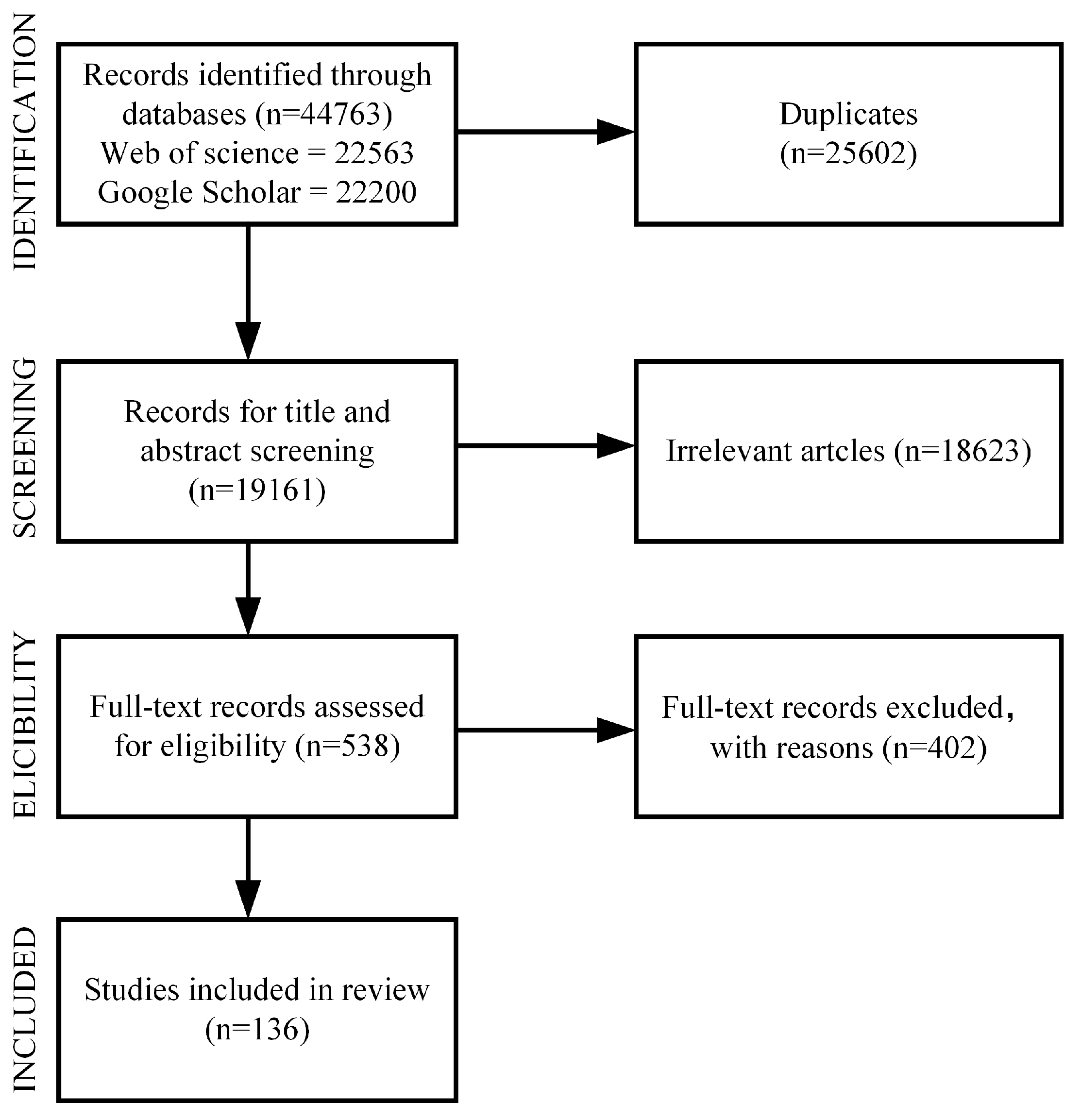
Figure 1. PRISMA flow chart.
Energies 18 00517 g001
Figure 2. The voltage induced at both ends of the shaft due to the tangential magnetic flux: (a) the tangential magnetic flux; (b) bearing current flow path.
Energies 18 00517 g002
Figure 3. Shaft-to-ground voltage due to electrostatic effect: (a) electrostatic effect; (b) bearing current flow path.
Energies 18 00517 g003
Figure 4. Types of bearing wear: frosting [16], pitting [15], spark marks [13], welding [13], and fluting [16].
Energies 18 00517 g004
Figure 5. Bearing voltage of inverter drive system: (a) neutral voltage; (b) motor parasitic parameters.
Energies 18 00517 g005
Figure 6. Electrical discharge machining bearing current.
Energies 18 00517 g006
Figure 7. High-frequency circulating bearing current.
Energies 18 00517 g007
Figure 8. Rotor-to-ground bearing current.
Energies 18 00517 g008
Figure 9. EDM current mathematical model.
Energies 18 00517 g009
Figure 10. Bearing mathematical model.
Energies 18 00517 g010
Figure 11. Bearing current suppression method.
Energies 18 00517 g011
Figure 12. A flow chart of a method for predicting bearing failures by means of artificial intelligence.
Energies 18 00517 g012
Figure 13. Common-mode equivalent circuit.
Energies 18 00517 g013
Figure 14. Common-mode voltage suppression based on SVPWM: (a) AZS-PWM; (b) NS-PWM.
Energies 18 00517 g014
Figure 15. Common-mode voltage suppression based on CBPWM: (a) carrier phase shift PWM principle; (b) switching state corresponding to 180° carrier phase shift PWM.
Energies 18 00517 g015
Figure 16. Dual three-phase inverter voltage vector: (a) αβ subplane; (b) xy subplane.
Energies 18 00517 g016
Table 1. Characteristics of various methods for calculating parasitic parameters.
MethodAdvantagesDisadvantagesApplication ScenariosError RangeCalculation Time
Analytical MethodFast calculation speed, suitable for initial design or simple geometries.Limited accuracy for complex structures, unable to fully consider parasitic effects.Used for quick estimation of simple motor geometries.LargeFast
Two-Dimensional Finite Element MethodBalances accuracy and efficiency, suitable for planar symmetrical structures.Only applicable to 2D structures, unable to capture complete 3D interactions, such as edge effects of windings.Suitable for moderately complex planar symmetrical designs.MediumMedium
Three-Dimensional Finite Element MethodHigh accuracy, suitable for complex and asymmetrical structures.Time-consuming with large computational demands.Suitable for final verification of high-precision complex motor designs.SmallSlow
Table 2. Comparison of two methods for suppressing bearing current on the inverter side.
AspectInverter Hardware OptimizationInverter Control Mode Optimization
Implementation DifficultyHigh, involves hardware replacement and complex circuit optimizationLow, mainly depends on software adjustment, fewer hardware requirements
Implementation CostHigh, requires hardware replacementLow, only involves control software
Effectiveness and LongevityHigh, through hardware optimization, long-term effectsMedium, depends on control algorithms, may have environmental variability
Effect on Suppressing Bearing CurrentStrong, optimized hardware circuits can significantly reduce bearing currentMedium, optimized control mode can smooth bearing currents, but with limited results
System CompatibilityRequires redesigning several subsystems, lower compatibilityHigh, can adapt to existing systems quickly, no major upgrades needed
Maintenance and Upgrade DifficultyHigh, expanding and optimizing require hardware maintenance and upgradesLow, optimization can be achieved through software upgrades
AspectInverter hardware optimizationInverter control mode optimization
Table 3. Comparison of different types of bearing current suppression.
MethodEDM CurrentCirculating Bearing CurrentShaft-to-Ground Current
Passive FilterNo significant impactReduces by 30–50%No significant impact
Active FilterReducesSignificantly reducesSignificantly reduces
Common-Mode ChokeNo significant impactReducesNo significant impact
Shielded CableNo significant impactMay increaseReduces
MethodEDM currentCirculating bearing currentShaft-to-ground current
Passive FilterNo significant impactReduces by 30–50%No significant impact
Active Filter (ACC)ReducesSignificantly reducesSignificantly reduces
Table 4. The current research on bearing current suppression.
SolutionDescriptionAdvantagesDisadvantagesReferences
Insulated bearingsUse insulated bearings at the non-drive end to block the current path.Effectively blocks the circulating current path and reduces the risk of bearing current.The price is high, installation and maintenance are complicated, and mechanical performance may be affected.[27,30]
Shaft grounding brushesInstall grounding brushes on the shaft to provide a low impedance path to shunt bearing current.Economical and effective, suitable for most application scenarios, simple to install.The bristles may wear out and need to be replaced regularly, and the life span is limited.[27]
Capacitor bypassConnect capacitors in parallel at both ends of the bearing to provide a low-impedance path to shunt the high-frequency current.Effectively reduces high-frequency current, low cost.The capacitance value needs to be selected accurately, which is not suitable for all scenarios.[81]
Winding electrostatic shieldingAdd shielding layers to the windings to reduce the capacitive coupling of the windings to the bearings.Effectively reduces bearing voltage, suitable for high-frequency scenarios.Increases design complexity and cost, and the design needs to be optimized to reduce losses.[77,82]
Common-mode filtersAdd common-mode filters to the inverter output to reduce the common-mode voltage amplitude and dv/dt.Reduce the generation of bearing current from the source and protect the overall system.The filter design is complex, the cost is high, and it takes up a lot of space.[71,79]
Active filtersThrough the control algorithm inside the filter, the active filter generates a compensation signal that is the opposite of the undesirable waveform in the power supply.The active filter can dynamically adjust the compensation strategy as needed to adapt to the current demand under different loads and working conditions, and has strong adaptability.Active filters require the design and implementation of more complex control algorithms and circuits, so the system structure is more complex.[70]
Passive filtersA circuit composed of passive components (such as resistors, inductors, and capacitors) to filter out high-frequency noise and harmonics in the power supply.Passive filters are simple to design and generally less expensive than active filters and other complex mitigation methods.Passive filters have limited effectiveness in suppressing harmonics, especially over a wide frequency spectrum.[67,68]
Lubricant improvementsUse high-impedance grease to increase the breakdown voltage of the lubricating film and reduce the possibility of arc discharge.Easy to use, improves bearing life, suitable for most scenarios.The high impedance of grease may reduce other properties and require frequent replacement.[83,84]
Inverter topology optimizationA method for suppressing motor bearing current by optimizing the design of the inverter involves adjusting the output characteristics and control strategy of the inverter.The topology can be adjusted according to actual needs to better adapt to different working environments and load conditions.Optimizing inverter topology involves complex circuit design and control algorithms, which may require modifications to existing systems.[65,66]
PWM modulation optimizationOptimize PWM modulation strategies, such as reducing switching frequency or using a three-level inverter to reduce dv/dt.The generation of high-frequency current can be fundamentally reduced.May reduce system efficiency and increase inverter complexity and cost.[85,86,87]
Stator slot grounding electrodesThis way, by connecting the stator slots to the ground, it is possible to introduce the current in the motor to the ground effectively.The design of the grounding electrode is relatively simple and does not require additional complex control systems or equipment.Improper grounding design may cause changes in the stator electromagnetic field, thus affecting the operating efficiency and performance of the motor.[73,74,78]
Motor design optimizationOptimize motor design through finite element analysis, such as improving the stator winding arrangement and the stator slotting method to reduce parasitic capacitance.Improve overall motor performance and reduce parasitic capacitance coupling.The design is complex and needs to be optimized for each application scenario, resulting in high R&D costs.[75,76]
Table 5. Comparison of different optimization methods based on SVPWM.
Method Typical MethodsCMV Suppression EffectLossEfficiencyApplicability
Switching State Selection- AZS-PWM
- NS-PWM
Reduces common-mode voltage to Vdc/6Relatively lowHighSuitable for two-level and three-level inverters, and applications with relatively low performance requirements
Vector Synthesis- Virtual Space Vector PWMReduces common-mode voltage to Vdc/6 HigherLowerSuitable for two-level and three-level inverters, and scenarios requiring higher output performance
Switching State Action Time- Adjust Zero Vector Action TimeReduces common-mode voltage amplitudeMediumRelatively highBack-to-back system or parallel inverter system
Switching State Action Sequence- Reorder Switching SequenceCompletely eliminates common-mode voltageLowMediumBack-to-back system or parallel inverter system
Table 6. Comparison of different optimization methods based on CBPWM.
MethodTypical MethodsComplexityCMV Suppression
Effect
Features and
Applicability
Carrier AdjustmentCarrier phase shift, changing the direction of the carrier, the angle of the carrier, and the peak position of the carrierLowPartial suppressionThe suppression effect is good, but the harmonics are large; it is suitable for parallel and back-to-back inverters.
Modulation Wave AdjustmentZero-sequence injection, dual modulation wave, wave decompositionHighPartial suppressionZero-sequence voltage injection is flexible and has a wide range of applications; dual modulation waves are suitable for high-performance applications; but the control is complex, and the loss increases.
Table 7. The common-mode voltage (CMV) corresponding to the voltage vector.
Voltage VectorCMV
000−1/2 × Udc
001−1/6 × Udc
0111/6 × Udc
0101/6 × Udc
1101/6 × Udc
100−1/6 × Udc
1011/6 × Udc
1111/2 × Udc
Table 8. The common-mode voltage corresponding to the voltage vector.
Voltage vectorCMV
v001/2 × Udc
v77−1/2 × Udc
v37, v57, v67, v73, v75, v761/3 × Udc
v01, v02, v04, v10, v20, v40−1/3 × Udc
v35, v56, v63, v17, v27, v47
v71, v72, v74, v36, v53, v65
v33, v55, v66
1/6 × Udc
v14, v21, v42, v03, v05, v06
v30, v50, v60, v12, v24, v41
v11, v22, v44
−1/6 × Udc
v07, v70, v16, v25, v34, v43
v52, v61, v15, v23, v31, v46
v54, v62, v13, v26, v32, v45
v51, v64
0
Disclaimer/Publisher’s Note: The statements, opinions and data contained in all publications are solely those of the individual author(s) and contributor(s) and not of MDPI and/or the editor(s). MDPI and/or the editor(s) disclaim responsibility for any injury to people or property resulting from any ideas, methods, instructions or products referred to in the content.