Review

A Review of Ignition Characteristics and Prediction Model of Combustor Under High-Altitude Conditions

1
National Key Laboratory of Science and Technology on Advanced Light-Duty Gas-Turbine, Institute of Engineering Thermophysics, Chinese Academy of Sciences, Beijing 100190, China
2
School of Aeronautics and Astronautics, University of Chinese Academy of Sciences, Beijing 100049, China
3
Qingdao Institute of Aeronautical Technology, Qingdao 266400, China
*
Author to whom correspondence should be addressed.
Energies 2025, 18(3), 527; https://doi.org/10.3390/en18030527
Submission received: 9 December 2024 / Revised: 17 January 2025 / Accepted: 20 January 2025 / Published: 23 January 2025
(This article belongs to the Section I2: Energy and Combustion Science)

Abstract

:
High-altitude relight is a critical challenge for aero-engines, directly impacting the safety and emergency response capabilities of aircraft. This paper systematically reviews the physical mechanisms, key factors, and relevant prediction models of high-altitude relight, highlighting the detrimental effects of extreme conditions such as low pressure and temperature on fuel evaporation rates, flame propagation speeds, and turbulent combustion processes. A comprehensive overview of the current state of high-altitude relight research is presented, alongside recommendations for enhancing the ignition performance of aero-engines under extreme conditions. This paper focuses on the development of ignition prediction models, including early empirical and semi-empirical models, as well as physics-based models for turbulent flame propagation and flame kernel tracking, assessing their applicability in high-altitude relight scenarios. Although flame kernel tracking has shown satisfactory performance in predicting ignition probability, it still overly relies on manually set parameters and lacks precise descriptions of the physical processes of flame kernel generation. Future studies on some topics, including refining flame kernel modeling, strengthening the integration of experimental data and numerical simulations, and exploring the incorporation of new ignition technologies, are needed, to further improve model reliability and predictive capability.

1. Introduction

Gas turbine engines play a critical role in modern aviation, as their operational stability directly determines flight missions. These engines rely on efficient fuel-air combustion to generate thrust, making ignition a vital process. Failure in ignition can result in engine startup failure or sudden shutdown, posing significant risks to flight safety [1].
During normal operation, ignition occurs either during engine startup on the ground or after a flameout at high altitude. Ignition is typically achieved by depositing a significant amount of energy locally to initiate a flame kernel and lead to full combustion [2]. Lefebvre [3], Mastorakos [4,5], and Yang [6] state that the ignition transient involves three phases: kernel generation, flame growth, and burner-scale flame establishment (including flame stabilization over a single burner and burner-to-burner propagation, known as “light-round”). In the first stage, the flame kernel develops into a flame, requiring sufficient energy to initiate droplet evaporation, sustain fuel pyrolysis, and ensure rapid oxidation of pyrolysis products. In the second stage, the flame generates enough heat within the initial ignition region to propagate to the central recirculation zone (CRZ) without extinguishing. This process is strongly influenced by fuel-air ratios (FAR) and the efficient evaporation of small droplets. Finally, in the third stage, the heat release rate continues to increase until the flame spreads to a stable position. If the flame can reach this stage, the ignition process is likely to succeed [5,7].
For the ignition process of gas turbines under ground-level conditions, extensive experimental and simulation studies have already been conducted by previous researchers [5], revealing that it is influenced by various factors, primarily including airflow speed [8,9], combustion chamber pressure drop, nozzle pressure drop, droplet size [10], inlet air temperature [11], geometric dimensions of the combustion chamber [12,13], the aerodynamic characteristics of the combustion chamber (such as cooling air near the igniter) and the energy output and frequency of the igniter [3].
In contrast, ignition at high altitudes introduces significant challenges due to reduced ambient pressure, temperature, and air density. These conditions disrupt the flow field within the combustion chamber and hinder critical processes such as atomization, evaporation, and flame propagation. The low-pressure environment slows the growth and propagation of the flame kernel, as the rarefied air decreases flame propagation speed. Additionally, the low-temperature conditions reduce the evaporation rate of liquid fuel, delaying its conversion into combustible gas. High-speed airflow further complicates the process by destabilizing the flame kernel, increasing the risk of ignition failure [3]. Addressing these challenges requires a deeper understanding of flame kernel generation and flame stability mechanisms under high-altitude conditions.
In recent years, high-altitude relight research has advanced significantly, evolving from theoretical foundations and experimental optimizations to the application of advanced technologies and prediction model development. Lefebvre [14] established a theoretical framework for Minimum Ignition Energy (MIE) under high-altitude conditions. Building on this, Chen [15] explored oxygen enrichment as a strategy to enhance ignition performance in low-oxygen environments. Structural optimizations have also been studied, with Read [16] and Linassier [17] investigating ignition performance in lean direct injection (LDI) and multi-sector combustors, respectively, revealing the influence of design configurations on ignition efficiency. Advanced diagnostic and ignition technologies have been employed by Mosbach [18] and Mehdi [19], who used laser diagnostics and plasma-assisted methods to analyze the dynamic effects of fuel injection and plasma excitation. Rosa [20] and Giusti [21] additionally combined numerical simulations and experiments to study two-phase flow ignition in liquid fuels, while Cambridge University researchers [22,23] developed and validated a low-order ignition model using Rolls-Royce data, advancing high-altitude relight prediction models. These studies, through the integration of theoretical, experimental, and technological approaches, have provided systematic support for high-altitude relight research.
High-altitude relight is critical for aviation safety, directly affecting aircraft performance and emergency response capabilities. Understanding flame propagation and ignition mechanisms under high-altitude conditions is essential not only for improving current aero-engine performance but also for guiding the development of future low-emission engines. However, the lack of comprehensive analysis of flame propagation characteristics and predictive methods for combustors under extreme conditions has become a limiting factor for flight safety after flame blowoff in combustors. This paper aims to address these gaps by providing a detailed review of the physical mechanisms and key factors influencing high-altitude relight. It will analyze airflow dynamics, fuel atomization, and evaporation processes, as well as flame propagation and stability theories. The advantages and limitations of current ignition prediction models will also be evaluated, with a focus on their applicability and accuracy for high-altitude conditions. Finally, the paper will identify current research gaps and propose directions for future work in high-altitude relight.

2. Ignition and Flame Establishment Mechanisms

2.1. Current Research Status on Ignition Characteristics

Ignition is a highly intricate and multifaceted area of combustion research. Its performance plays a pivotal role in determining the operating envelope of an aircraft and the combustor volume, which in turn influences engine weight, energy losses, and emissions. Forced ignition refers to the initiation of combustion in a mixture through externally imposed energy sources such as electrical or laser-induced sparks [24,25,26,27], plasma jets [28,29], or heated surfaces [5]. In turbulent combustion, flames are broadly classified into premixed flames [8,30,31] and non-premixed flames [4,32], the latter can be further categorized into stratified flames [33] and spray flames [5,34,35,36], with spray flames being the most prevalent type in aero-engine applications. Figure 1 depicts canonical flame propagation, illustrating laminar flame propagation in a uniform liquid spray field, spark ignition in a uniform liquid spray, and flame propagation in a non-uniform liquid spray.
Researchers globally have conducted extensive studies on ignition stages and flame propagation characteristics. For the kernel generation stage, Mastorakos [5] summarized three probabilistic factors to describe the stochastic nature of ignition. The likelihood of finding a combustible mixture in the spark region is defined as the flammability factor, expressed as:
F = ξ l e a n ξ r i c h P ( η ) d ( η )
Here, P ( η ) denotes the probability density function of the local equivalence ratio η , while ξ r i c h  and ξ l e a n  collectively define the flammable range. Variations in the ionization path between electrodes, local droplet distribution, and turbulence strain rate influence the kernel establishment probability P k e r , which in turn impacts the overall ignition probability P i g n . Successful ignition requires the spark to release sufficient energy for the kernel diameter to exceed the quenching diameter [40]. Typically, the ignition energy that can form a flame in 50% of ignition events is referred to as the Minimum Ignition Energy (MIE) [5]. Shy described two statistical methods for determining the MIE at 50% ignitability [8]: the midpoint approximation method and the logistic regression method. The midpoint method estimates ignition probabilities at different energy levels through interpolation and progressively approaches 50% ignition probability to determine MIE. Its advantage lies in its intuitive process and clear experimental results, but it requires numerous test points, making it labor-intensive. The logistic regression method, on the other hand, relies on the cumulative distribution of ignition probabilities and uses statistical modeling to calculate MIE, including confidence intervals. This method is more robust and requires fewer experiments but demands advanced data processing and statistical modeling capabilities.
Neophytou [41] proposed that the success of ignition depends on the number of droplets surrounding the ignition kernel. In the initial ignition phase, a highly wrinkled flame surface forms around the droplets, with high reaction rates near them and low reaction rates in the gaps. Heat diffusion in the reaction zone triggers the ignition of nearby cold droplets, further sustaining the combustion process. The timescale of droplet evaporation interacts with chemical and diffusion timescales, determining the overall ignition process. If the droplet evaporation rate is too slow, this interaction may compete with chemical reactions, potentially leading to flame extinction. Figure 2 schematically illustrates features of forced ignition in turbulent non-premixed flames, focusing on flame propagation in turbulent fuel jets through cold air after successful ignition.
Aggarwal [10] proposed that ignition in two-phase mixtures occurs in three different modes (see Figure 3): droplet ignition, droplet cluster ignition, and spray ignition. An optimal droplet size and equivalence ratio for ignition in liquid fuel sprays correspond to the minimum ignition delay time (or ignition energy). Figure 4 illustrates the variation of MIE with droplet size and air-fuel ratio.
In the context of premixed flame ignition, Shy [8] investigated the phenomenon of spark ignition transition in premixed turbulent combustion. The study explored how factors such as spark gap, Lewis number, and turbulence velocity influence the MIE, with a particular focus on two distinct ignition phenomena: monotonic MIE transition and non-monotonic MIE transition. Yu [42] further advanced the theoretical understanding of premixed flame ignition, particularly the generation and expansion of flame kernels during forced ignition. Key ignition parameters, such as critical flame radius, MIE, and minimum ignition power, were analyzed, along with prediction models under various theoretical frameworks, including homogeneous explosion theory, hot spot ignition theory, flame ball theory, and transient ignition theory. These studies highlighted advancements in theoretical models for predicting critical ignition conditions, especially when considering the complex interactions between chemical kinetics and fluid dynamics.
During the flame growth phase, once a kernel is generated and a sufficiently large flame forms around the stoichiometric mixture fraction isosurface, the flame can propagate along it as a non-premixed edge flame [4]. Rosa [20] demonstrated experimentally that the successful propagation of the flame kernel depends on its movement within the fuel spray region. The axial spark position significantly impacts ignition performance and the flame propagation process. The propagation trajectory of the flame kernel is related to the ignition location and is primarily influenced by the non-reactive flow field and fuel concentration, warranting further investigation [43]. Marchione [12] summarized the optimal ignition locations for bluff-body flames under single-spark and multiple-spark conditions through multiple experiments, as shown in Figure 5. It was observed that, under high-frequency ignition conditions, the optimal position of the igniter is at the axial location corresponding to the widest radial extent of the recirculation zone.
During the flame propagation phase, the process is complex and variable, influenced significantly by boundary conditions and operating parameters [44]. The flame propagation mode is determined by the flow conditions, injection patterns, and flame shape. Flow structure and injection patterns establish potential flammable pathways for flame propagation, while flame morphology dictates the motion path of the flame front during ignition. Gao [45] proposed three mechanisms for injector-to-injector flame propagation patterns in annular combustors based on flame front behavior: spanwise upstream pattern, archlike-entrainment pattern, and spanwise-entrainment pattern (see Figure 6). The solid green lines show flame paths, and the black dashed lines outline recirculation zones. The spanwise-upstream pattern demonstrates the flame’s azimuthal and upstream movement, igniting downstream droplets before stabilizing in the unignited injector’s recirculation zone, which occurs under low velocity and high equivalence ratio conditions. The archlike-entrainment pattern shows the flame forming an arch shape as it moves across the merging jets, becoming entrained in the adjacent injector’s recirculation zone, and stabilizing as a kernel, typically under lean conditions. The spanwise-entrainment pattern describes a flame pathway characterized by radial movement and recirculation zone entrainment, prevalent under high-velocity conditions where the flame is short and wide. Similarly, Wang [46], from the perspective of local interactions in the flow field and combustion process, summarized the flame propagation modes in annular combustors with centrally staged swirl burners as the kindled-swirling pattern, entrained-swirling pattern, and sweeping pattern.
Topperwien [44] discovered that the volumetric expansion of combustion gases induces azimuthal flow acceleration, which serves as the primary driving mechanism for flame propagation. In the wake of rotating jets, droplets accumulate ahead of the propagating flame front, forming a characteristic sawtooth pattern in the trajectory of the leading points. Compared to non-staged combustors, staged combustors exhibit a more intricate “sawtooth” pattern during the light-round process. During this process, flame-leading points follow a zigzag motion, with counterclockwise trajectories closer to the inner wall and clockwise trajectories closer to the outer wall [47].
Microwave plasma extends combustion limits and shortens ignition delay, offering greater flexibility and stability compared to traditional spark ignition, particularly under lean burn and high-altitude conditions.
For advanced ignition technologies, plasma-assisted ignition, using low-temperature non-equilibrium plasma, has been demonstrated to effectively improve ignition and combustion performance under low pressure and temperature conditions. Mehdi et al. [19] investigates plasma-assisted ignition for re-igniting aeroengines under high-altitude, low-pressure conditions. The results show that plasma significantly reduces ignition delay times, with a reduction from 1.1 × 10⁻³ s to 3.5 × 10⁻⁵ s at 1 bar. At lower pressures (0.6 bar and 0.4 bar), the effect is less pronounced but still beneficial. Plasma improves fuel/air mixture mixing and enhances active radicals (H, O, OH, CH et al.), accelerating ignition. Lin et al. [29] used multi-channel nanosecond discharge plasma to achieve successful ignition of premixed fuels at low pressures, showcasing the effectiveness of microwave plasma ignition in comparison to other ignition methods. He et al. [48] provided a review of microwave plasma ignition, highlighting its potential in modern combustion technology to widen the ignition range, improve combustion efficiency, and reduce emissions.
Laser ignition technology has also been rapidly advancing. O’Briant et al. [49] reviewed the application of laser ignition in aerospace propulsion systems, noting that laser ignition provides precise timing for ignition, improves ignition efficiency, and extends the operational limits of aero-engines, especially under high-pressure and hypersonic flight conditions. Mulla et al. [26] studies the development of flame kernels in laser-induced spark ignition mixtures, focusing on their growth over time in different fuel mixtures. Using OH-PLIF imaging, the study tracks the flame kernel’s formation from 3 µs to 1000 µs. It finds that factors like fuel composition, equivalence ratio, and laser energy significantly affect kernel growth. Hydrogen mixtures show a larger flame kernel spread and higher laser energy leads to greater flame kernel expansion. The study conducted by de Oliveira et al. [50] investigates the ignition of droplet-laden turbulent flows using laser sparks, examining the effects of laser energy, equivalence ratio, and fuel pre-vaporization on flame kernel formation. It finds that small droplets enhance ignition by reducing the MIE and improving flame propagation, whereas larger droplets may hinder ignition. A critical kernel size of 1 mm is identified for successful ignition. The ignition probability is significantly increased by higher laser energies (80 mJ) and partial fuel pre-vaporization. Moreover, a positive correlation is observed between kernel size and absorbed energy. Yi et al. [51] studied the laser ignition characteristics of aviation kerosene droplets under different pressures and initial diameters and developed a droplet ignition model to calculate the MIE of RP-3 droplets at specific diameters and pressures. These studies highlight the potential of laser ignition technology in high-pressure, low-temperature, and lean fuel conditions, providing crucial theoretical support for the development of ignition techniques in aerospace propulsion systems.
This section reviews key advancements in ignition and flame propagation research, revealing the complex mechanisms from flame kernel generation to flame propagation. It also explores the impact of combustor design, fuel characteristics, environmental conditions, and advanced ignition technologies on ignition performance. Under high-altitude, low-temperature, and complex operating conditions, novel technologies such as microwave plasma and laser ignition have significant potential to extend combustion limits, accelerate flame propagation, and improve ignition probability. Optimizing ignition performance relies not only on improvements to individual factors but also on achieving higher integration through the synergistic interaction of combustor design, fuel compatibility, and ignition technologies.

2.2. Ignition Under High-Altitude Conditions

When an aero-engine experiences a flameout due to specific incidents, the loss of energy causes the turbine to cease generating power, leaving the engine in a windmill state, where the fan and compressor are passively rotated by external airflow without active ignition. Reigniting the combustor in this state is referred to as high-altitude relight [52]. High-altitude relight characteristics are typically described by relating relight altitude to aircraft flight speed. These characteristics define the relight flight envelope of an aircraft under different flight speeds. Currently, the international standard for high-altitude relight reaches altitudes of 8–12 km. Figure 7 illustrates the typical aero-engine flight envelope.
Under high-altitude conditions, significant reductions in air pressure, temperature, and density deteriorate flow and spray conditions, making ignition in the combustor more challenging. As air density and pressure decrease, turbulence intensity weakens, reducing the shear effect on fuel [53], increasing droplet size, and slowing evaporation rates. These factors degrade fuel atomization, leading to locally low FAR, which in turn reduces the efficiency of fuel-air mixing, increases ignition difficulty, and negatively impacts flame propagation speed and stability during the ignition process. Figure 8 illustrates the trend of minimum ignition FAR as the altitude increases. As shown by the red line in the figure, the minimum ignition FAR increases as temperature and pressure conditions deteriorate. Low temperatures at high altitudes slow fuel evaporation, preventing the formation of a sufficient concentration of combustible mixtures and causing longer ignition delays or even ignition failure [15].
In numerical simulations, reduced fuel temperature under high-altitude conditions significantly decreases fuel-air mixing uniformity. This uneven distribution of fuel in the combustion zone, with locally over-rich or lean areas, further increases the likelihood of ignition failure [17]. Zhao [55] found in the study of a multi-swirl staged combustor equipped with a pre-filming airblast atomizer that low-temperature and low-pressure conditions can significantly weaken the turbulent kinetic energy and tangential shear force of the swirling air, leading to larger atomized droplets, deeper penetration of droplet groups, and further deterioration of fuel distribution quality. In a study of high-altitude ignition processes in aero-engines with and without effusion cooling, Martinos [54] concluded that increasing FAR can compensate for the negative effects of low pressure and temperature on combustion reactions.
The generation and propagation of the flame kernel, and the alignment of fuel with the spark plug, are key challenges in high-altitude ignition. MIE is a critical parameter for understanding ignition processes, particularly under high-altitude conditions. Studies by Ballal and Lefebvre [56] have demonstrated that the MIE increases significantly as air pressure and temperature decrease. Their experimental measurements under sub-atmospheric pressures showed that MIE for liquid sprays is highly sensitive to spray SMD, airflow velocity, and equivalence ratio. They found that reduced air pressure and temperature not only lead to a significant increase in MIE but also necessitate higher spark energy and longer ignition duration. This indicates that atomization quality and fuel spray properties play a crucial role in achieving reliable ignition under such extreme conditions. Future research could focus on refining these relationships and expanding experimental studies to quantify MIE under high-altitude environments, where low turbulence intensity and suppressed flame kernel growth further complicate ignition.
Under high-altitude conditions, turbulent flame propagation modes directly influence the formation and expansion of flame kernel [18]. Read et al. [16] conducted high-speed imaging of the ignition process at Rolls-Royce’s high-altitude relight test rig in Derby, UK. They found that the success of ignition strongly depends on the overall FAR of the combustor and, to a great extent, on the trajectory of the flame kernel. Flame kernels that enter the CRZ of the combustor typically lead to flame stabilization, while those flowing toward the combustor exit tend to extinguish. Mosbach [18] further revealed that the success of ignition depends on the flame kernel’s ability to move upstream from the igniter to the fuel atomization region. Flame kernels that successfully develop into sustained ignition typically exhibit pronounced upstream movement, while those that fail to ignite remain localized downstream and eventually extinguish, primarily due to adverse turbulence effects or insufficient energy. Zhao [57] summarized a high-probability flame propagation pattern (dipper-type propagation, see Figure 9), which supports this conclusion.
Linassier [17] found that the flame kernel is typically generated in fuel-rich regions within the combustor, and its propagation path is significantly influenced by airflow and fuel distribution. The study showed that a successful ignition process relies on the flame kernel quickly propagating from the spark plug to the fuel atomization region. If the flame kernel cannot move upstream and reach the fuel injection region within a short period, ignition is highly likely to fail [16]. Figure 10 illustrates four trajectories of the flame centroid, corresponding to flame kernel failure following high-altitude relight attempts. The spark plug position and discharge energy intensity significantly impact flame kernel formation and propagation path [58]. Adjusting the axial position of the igniter or increasing its discharge energy can substantially improve the probability of high-altitude ignition [18]. Vincenti [58] demonstrated that flame kernel generation and propagation depend on fuel atomization quality and igniter position. In regions with uneven fuel distribution, ignition probability significantly drops. Adjusting the igniter’s position increases the probability from 50% to over 80%. Doubling the igniter’s discharge energy compared to standard systems improves the probability by 20%.
The geometry of the combustor has a significant impact on high-altitude ignition performance, and the optimization of different components within the combustor plays a crucial role in improving ignition reliability under adverse conditions.
For the combustor dome, Wang et al. [59] demonstrated the critical influence of two-stage axial swirlers on ignition characteristics. By reducing the outer swirl number, the shear strength between inner and outer swirling airflows was enhanced, improving fuel atomization and ignition stability. Furthermore, adjusting the effective area ratio between the swirlers and modifying the Venturi throat radius optimized ignition performance under low-pressure and high-altitude conditions. Fu et al. [60] investigated the effect of step heights at the dome outlet in centrally staged combustors. They found that increasing step height significantly improved lean ignition performance under high-altitude conditions, particularly due to enhanced fuel atomization. This impact was more pronounced under low-pressure conditions, emphasizing the importance of step height in stabilizing ignition.
For the combustor liner, Li et al. [61] systematically studied the effects of sleeve length and large cooling holes (LCHs) on ignition processes in reverse-flow combustors. Their research showed that plugging LCHs and shortening the sleeve length enhanced the recirculation zone and facilitated better energy and radical transfer, resulting in improved ignition performance even at altitudes of 8.5 km. Yang et al. [62] explored the axial positioning of primary holes along the combustor liner. Their study revealed that aligned primary holes expanded the recirculation zone and reduced the reference velocity, creating a more stable flame and minimizing the quenching probability of the flame kernel. This configuration supports flame propagation and ensures ignition reliability under low-temperature and low-pressure conditions.
By integrating these findings, it becomes evident that a synergistic approach to combustor design, encompassing swirler configuration, dome outlet step height, cooling hole management, sleeve length, and primary hole positioning, enhances ignition reliability and advances the development of high-efficiency combustors for aviation applications.
One of the challenges in high-altitude relight testing is that ground-based test equipment must accurately simulate real high-altitude conditions, which imposes high demands on the complexity and cost of the experimental setup. The high-altitude environment features extremely low pressure and temperature, requiring the test equipment to create a similar vacuum environment and maintain a high-precision temperature control system to ensure that the engine can relight under realistic conditions.
There are several renowned ignition testing platforms worldwide. The Rolls-Royce Strategic Research Centre (SRC) altitude-relight test rig in Derby, UK, has been used to test the high-altitude relight performance of a lean fuel injector and combustor. This test rig can operate a sector combustor with an inlet pressure as low as 0.2 bar (20 kPa), an inlet temperature of 243 K, and an airflow of up to 1.77 lb/s (800 g/s). Flame behavior can be observed through quartz windows in the sidewall of the combustion chamber and pressure vessel [18]. Researchers, including Read [16] from the University of Cambridge and Mosbach [18] from the German Aerospace Center (DLR), studied the high-altitude relight performance of lean fuel at operating pressures of 50 kPa and 41.7 kPa, respectively, based on this testing platform. Nicolás [20] from Toulouse University and Linassier [17] from France conducted high-altitude studies on single-head and multi-sector combustor models using the MERCATO (Moyen Expérimental de Recherche en Combustion Aérobie par Techniques Optiques) test rig at ONERA Fauga-Mauzac. This facility analyzes two-phase flow injection systems and reproduces high-altitude combustor conditions, with pressures as low as 0.4 bar and air-fuel temperatures down to 233 K. For more information, refer to refs. [63,64].
The Combustion and Fire Research Laboratory (CFRL) at the University of Cincinnati designed and constructed the High Altitude Relight Test Facility (HARTF) [65,66]. HARTF successfully simulates the atmospheric environment in the combustor region from sea level to altitudes above 10,700 m. Diagnostic methods compatible with this facility include high-speed flame imaging, combustion emission analysis, laser sheet spray visualization, phase Doppler particle analysis (PDPA), and high-speed particle image velocimetry (HSPIV). The ISCAR (“Ignition under Sub-atmospheric Conditions Altitude Relight”) rig was designed and manufactured at the Engler-Bunte Institute of Karlsruhe Institute of Technology (KIT), where Majcherczyk et al. studied the impact of turbulence on spark ignition [67], and Martinos investigated ignition processes in aero-engine combustors under high-altitude conditions with and without effusion cooling [54]. Zhao’s [34,68] ignition experiments are conducted in the gas turbine model combustor facility at the Institute of Engineering Thermophysics (IET), Chinese Academy of Sciences (CAS) to investigate the influence of sub-atmospheric pressure under high-altitude conditions on relight performance, flame propagation modes, and the lean blowout dynamics of spray flames. The test rig can achieve conditions as low as 0.1 bar in pressure and 213 K in temperature.
The operating conditions of the test rigs summarized from the above literature are shown in Table 1. Rigs like Rolls-Royce’s SRC rig and ONERA’s MERCATO excel in optical diagnostics, providing high-resolution visualization of flame propagation, spray breakup, and two-phase flow interactions under simulated high-altitude conditions. These capabilities are essential for studying flame stability and ignition boundary dynamics in lean combustor designs. Facilities such as HARTF and ISCAR place greater emphasis on turbulence effects and particle-level interactions, utilizing advanced diagnostic techniques like PDPA and HSPIV to analyze ignition turbulence and flame kernel dynamics. The SRC rig operates at pressures as low as 0.2 bar and temperatures below 243 K, while the MERCATO rig covers a wider range with pressures from 0.5 to 1 bar and temperatures as low as 233 K. HARTF achieves pressures down to 0.276 bar and temperatures down to 227 K, whereas ISCAR operates at pressures of 0.4 bar and temperatures of 253 K. The IET rig from CAS enables relatively more extreme conditions, achieving pressures as low as 0.1 bar and temperatures down to 213 K. These high-altitude relight testing rigs not only provide valuable data for the design and optimization of aero-engines but also establish a foundation for addressing the challenges of more efficient and environmentally friendly combustion systems in future aviation technologies.
It is worth noting that under high-altitude conditions, the reduced air density and pressure are often accompanied by microgravity-like effects, which significantly affect flame propagation dynamics. Research has shown that in the absence of gravity, the lack of buoyancy leads to different flame behaviors. In microgravity, flames tend to become more spherical, and the transport of heat and mass relies solely on diffusion, affecting flame propagation dynamics [69]. Studies indicate that buoyancy effects in normal gravity can stabilize flames by producing vorticity that opposes flame wrinkling. In microgravity, the removal of this stabilizing mechanism results in increased flame wrinkling amplitude and flame speed [70]. These findings are highly relevant to high-altitude ignition scenarios, where similar low-gravity effects may influence ignition probabilities and flame stabilization mechanisms.
High-altitude ignition processes are fundamentally constrained by low pressure, temperature, and density, which influence fuel atomization, evaporation, and mixing with air, thereby influencing flame kernel generation and propagation. A critical aspect is the matching between the spatial distribution of fuel and the concentration field required for effective flame propagation, which significantly affects ignition performance and the trajectory of the flame kernel. The generation and propagation of flame kernels toward the CRZ are critical for ignition success, with key influencing factors including droplet size, turbulence intensity, and local equivalence ratio. The findings emphasize that optimizing combustor geometry, such as swirler configurations and igniter positioning, can improve fuel-air mixing and stabilize the flame. Increasing the overall FAR can partially mitigate the negative effects of low-temperature and low-pressure environments on ignition.
To expand the high-altitude ignition boundary, future research should prioritize improving fuel atomization through advanced atomizers or modified swirler designs to enhance droplet breakup and mixing efficiency. In addition, advanced ignition technologies, such as plasma-assisted or laser ignition, hold promise for reducing MIE requirements and increasing flame stability under extreme conditions, thereby further extending the ignition boundary.

3. Prediction Models of High-Altitude Relight

High-altitude relight prediction models are crucial for studying ignition probability and flame propagation in aero-engines under conditions of rarefied air, low pressure, and low temperatures. These models combine numerical simulations with experimental data to predict engine ignition performance under extreme conditions and provide theoretical support for optimizing ignition systems. With the continuous advancement of computational fluid dynamics (CFD) and turbulence combustion models, significant progress has been made in high-altitude relight prediction models in recent years.

3.1. Empirical Models

Initial high-altitude relight prediction primarily relied on empirical models, which used extensive experimental data, simplified assumptions, and empirical formulas to estimate the influence of key parameters on ignition boundaries. Ballal and Lefebvre’s classic ignition model simplified the fuel-air mixture and turbulence characteristics in the combustion chamber to estimate the MIE in relation to pressure, turbulence intensity, and fuel injection speed [71,72]. These empirical models were practical in the early design stages, particularly for preliminary assessments. However, they heavily relied on experimental data, limiting their applicability under extreme conditions, where they struggled to capture complex turbulence-combustion coupling phenomena.
To more accurately simulate the physical phenomena during ignition, researchers gradually transitioned to models based on physical and chemical mechanisms, which better explain flame propagation and ignition processes under different conditions. The characteristic time model proposed by Peters and Mellor [73,74] further optimized the description of ignition and flame propagation by introducing key combustion and fluid dynamics parameters. This model effectively considered the relationship between the characteristic time of flame propagation and the reaction time of the fuel-air mixture, laying the foundation for more complex turbulent combustion models.

3.2. Turbulent Flame Propagation Model and Numerical Computation

As the understanding of turbulent combustion processes advanced, researchers introduced turbulent flame propagation models to capture the complex turbulence effects during the generation, growth, and propagation of the flame kernel. Mastorakos [39] proposed a turbulence-based flame propagation model that analyzed turbulence effects on ignition processes, leading to more accurate predictions of ignition probability under high-altitude conditions. Direct Numerical Simulation (DNS) was used to simulate turbulent droplet-laden mixing layers with hydrocarbon fuels, incorporating detailed chemical reaction mechanisms to capture edge flame dynamics and spark-turbulence interactions. In this model, flame kernel generation is crucial for ignition. Turbulence enhances flame propagation but also increases the risk of flame kernel extinction. Ahmed and Mastorakos [75] conducted experimental and numerical studies on non-premixed bluff-body flames, exploring flame stabilization mechanisms and employing detailed combustion chemistry to model turbulent ignition processes. They found that the ignition probability of turbulent non-premixed bluff-body flames is significantly influenced by factors such as fuel and air velocities, mixing distribution, and turbulence intensity. The ignition location plays a critical role in determining the flame propagation direction. Swirl improves mixing but may lead to overly lean or rich mixtures in the CRZ, reducing ignition probability in this region.
With the advancement of computational capabilities, Large Eddy Simulation (LES) and DNS have emerged as the predominant methodologies for investigating high-altitude relight phenomena. LES is effective in capturing large-scale turbulence structures and providing detailed insights into flame propagation and the interactions between turbulence and combustion, while DNS solves the Navier-Stokes equations with high fidelity, simulating all turbulence scales throughout the flame propagation process, making it suited for studies involving small-scale geometries or simple configurations.
Barré et al. [76] investigated the influence of head spacing on flame propagation using LES, demonstrating good agreement between numerical and experimental results. Similarly, Boileau et al. [77] applied LES to simulate ignition processes in annular combustors, revealing that flame propagation speeds are significantly influenced by thermal expansion and head interactions, exceeding theoretical turbulent flame speeds. These studies underscore the capability of LES to capture complex flow and ignition phenomena, particularly in annular combustors with intricate flow structures. Eyssartier et al. [78] used LES to simulate ignition in a two-phase flow combustor, incorporating detailed two-phase interaction models with simplified chemistry for computational efficiency and proposed local ignition success criteria based on fuel droplet size, turbulence intensity, and spark energy to predict flame propagation and ignition reliability. Mesquita and Mastorakos [79] employed DNS to conduct a comprehensive analysis of the high-altitude relight process, demonstrating the profound impact of turbulence on flame kernel generation and expansion, particularly in complex low-pressure environments. Tang [80] developed a numerical model that integrates LES with a hybrid chemical reaction tabulation method to predict the probability of forced ignition in high-altitude turbulent non-premixed combustion (see Figure 11). The main innovation of Tang’s model lies in the introduction of a novel tabulation approach, which combines the flamelet-progress variable (FPVA) model with a homogeneous reaction model, allowing for a more precise representation of the transition from homogeneous reaction to diffusion-controlled flame behavior within the ignition kernel. In addition, the model incorporates the stochastic nature of turbulence and spark discharge, using multiple simulations to statistically estimate ignition probability, providing an efficient and reliable framework for the numerical prediction of high-altitude relight.
Although LES and DNS provide highly accurate results, their high computational cost limits their widespread application in engineering. To address this, researchers have developed RANS-LES hybrid models, which combine LES for simulating large-scale turbulence structures and RANS for modeling small-scale turbulence, significantly reducing computational costs while maintaining accuracy. The RANS-LES hybrid model strikes an effective balance between simulation accuracy and computational efficiency, making it a promising direction for future high-altitude relight prediction models. Among hybrid methods, Detached Eddy Simulation (DES) blends RANS and LES capabilities, effectively modeling near-wall flows with RANS and transitioning to LES for separated or large-scale turbulent regions. DES has been widely applied in numerous studies. However, its application to high-altitude ignition remains limited due to several factors. DES relies heavily on fine grid resolution for smooth RANS-LES transitions, which is challenging in complex ignition flows. In addition, its integration with detailed combustion models, including flame propagation and ignition dynamics, is underexplored, and its computational cost, while lower than LES, remains higher than traditional RANS-LES models. Despite these challenges, DES complements existing RANS-LES approaches by resolving large-scale turbulence with greater detail, offering opportunities for improving ignition modeling under extreme conditions. Continued development of DES and hybrid CFD methods holds potential for optimizing combustor performance in high-altitude relight scenarios.
The French research team developed the MIST (Model for Ignition STatistics), a statistical model designed to predict ignition probability in gas turbine combustors [81,82,83]. This model uses non-reactive flow field statistics to generate ignition probability maps, eliminating the need for extensive reactive flow simulations. It processes instantaneous non-reactive flow data to construct potential flame kernel trajectories, combining local turbulence intensity, flammability, and flow direction to predict ignition probability at various locations. Since the MIST only requires a single non-reactive flow simulation to produce a global ignition probability distribution, it significantly reduces computation time and cost, making it particularly well-suited for complex combustor geometries. In addition, this model has been validated across multiple combustion modes (such as premixed, non-premixed, and two-phase flows), providing an accurate and cost-effective prediction tool for ignition system design and optimization—an essential asset for ensuring reliable ignition in combustor design.

3.3. Flame Kernel Tracking and Improved Models

In high-altitude relight prediction models, flame kernel tracking has emerged as a widely adopted method due to its ability to evaluate ignition probability under cold flow field conditions. This approach monitors the generation and expansion of flame kernels, utilizing the Karlovitz number as a critical metric to assess whether a flame kernel will extinguish due to turbulence-induced stretching or successfully ignite the surrounding combustible mixture [4,78]. The Karlovitz number quantitatively describes the impact of turbulence on flame stability, with its calculation depending on local flow characteristics and mixture properties. By tracking the evolution of the flame kernel, researchers can predict whether it will propagate to regions of higher FAR and ultimately form a stable flame. This methodology has been validated in a range of canonical cases, such as bluff-body flames, counterflow turbulent flames, and spray flames, under controlled conditions.
One notable application of this method is the SPINTHIR code, developed by the University of Cambridge. This code has been employed by Rolls-Royce for predicting high-altitude ignition probabilities in low-emission aero-engines, demonstrating its practical relevance in engineering contexts [22]. The SPINTHIR model, as one of the pioneering frameworks in ignition prediction, simulates the trajectories of individual flame elements originating from a spark within generic flow fields containing droplets. Figure 12a illustrates the initial steps of this model as described in [23], where this process is repeated for different spark locations and spark shapes. The resulting statistics of π i g n are then compared to assess the relative performance of the sparks and their placement. Here, π i g n is the ignition progress factor, which is defined as the ratio of the number of cells in a burnt state to the total number of cells. The detailed steps of the model are as follows:
  • The fluid domain is divided into a regular grid of cells, with each cell can have two states: cold (unburnt) or burnt. All cells start in the cold state.
  • The simulation begins by defining a spark volume representing the ignition source, which is based on experimental observations. All grid cells overlapping the spark volume are switched to the burnt state, releasing a “flame particle” at their center. The size and shape of the spark volume are key parameters of the ignition system.
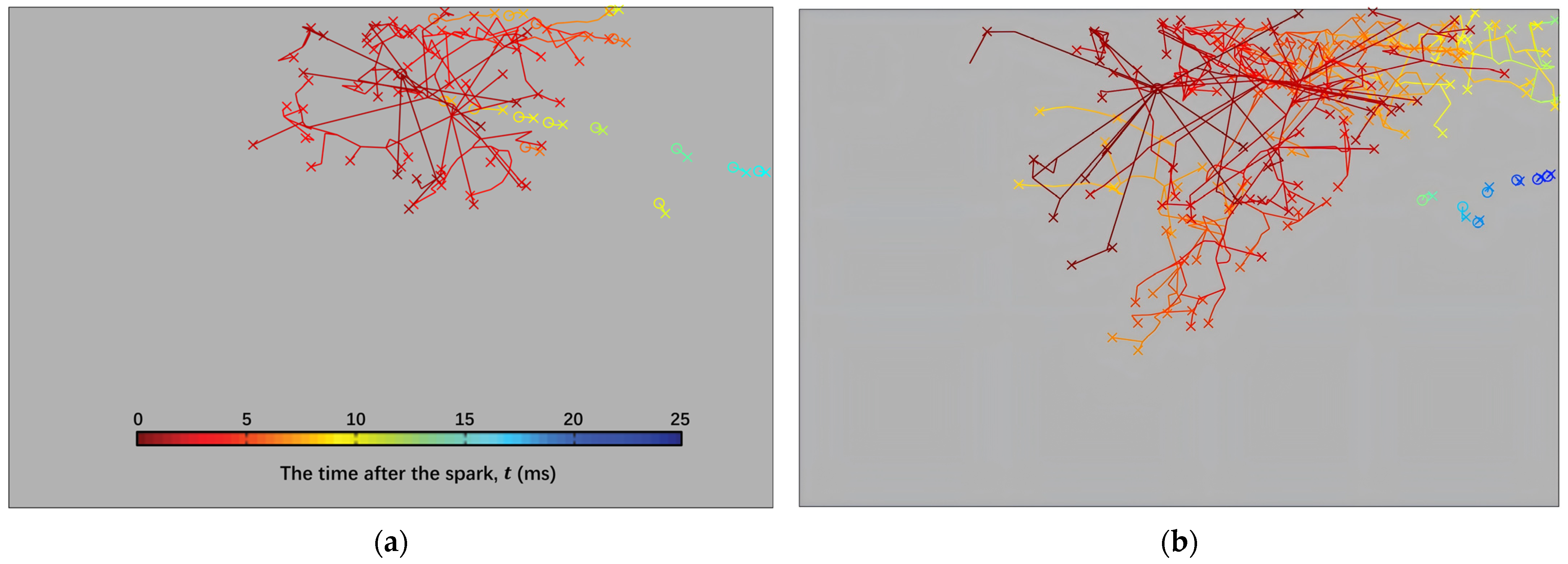
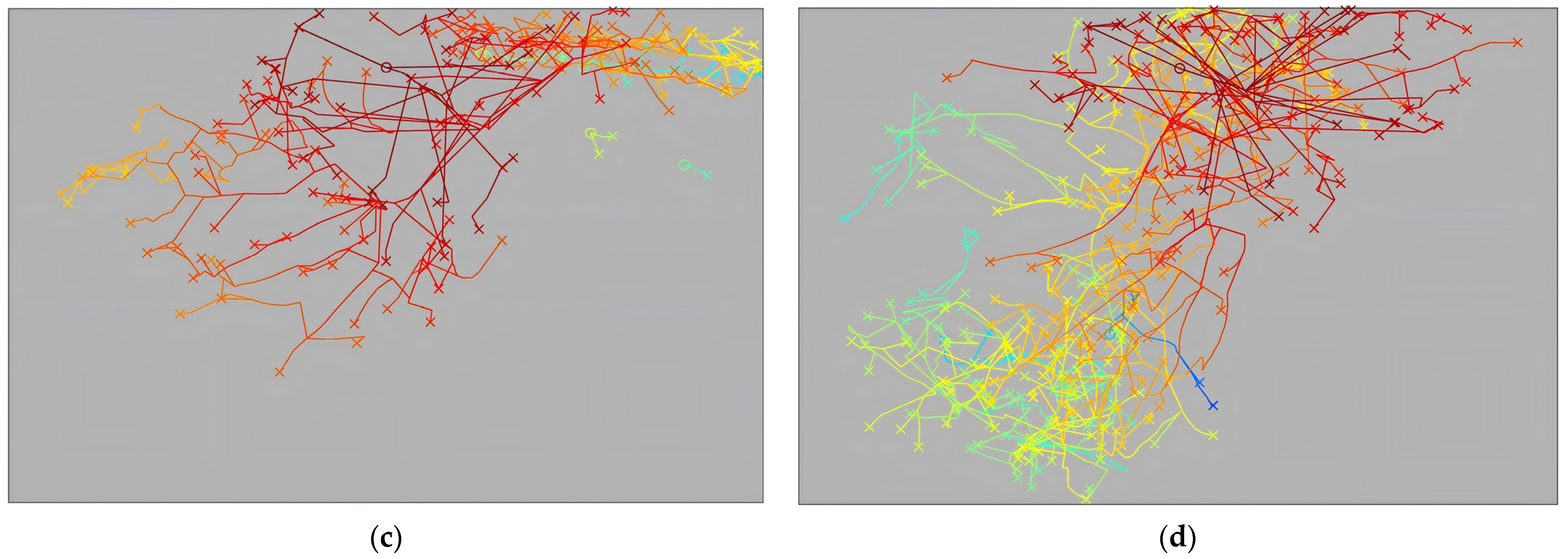
  • The particle position in direction i evolves according to the stochastic differential equation:
    d X p , i = U p , i d t
    where U p , i is the particle velocity in direction i . A flame particle is tracked using a Langevin model within the cold CFD field. Each particle is assigned a velocity and mixture fraction that consists of both mean and random components derived from the CFD solution. The U p , i consists of a linear drift towards the local Favre averaged velocity of the flow and an added isotropic diffusion term:
    d U p , i = 1 2 + 3 4 C 0 ω p U p , i U ~ i d t + ( C 0 ϵ p d t ) 1 / 2 N p , i
    where C 0  is a constant with a value of 2.0 [84], ω p is the inverse turbulent timescale at the particle location, U ~ i is the local Favre averaged velocity in direction i , ϵ p is the turbulent dissipation rate at the particle location, and N p , i is a random number following a standard normal distribution (mean of 0, variance of 1), assumed to be independent for each particle. The detailed calculation formulas for these parameters are provided in Appendix A. The particle mixture fraction ξ p is defined as:
    d ξ p = 1 2 C ξ ω ξ p ξ ~ d t + ( 1 ξ p ) Γ ¯ m ρ ¯ d t
    where C ξ  is a constant with a value of 2.0 [84], ξ p  is the particle mixture fraction, ξ ~  is the local Favre averaged mixture fraction, ρ  is the local flow density, and Γ m is the mass source term due to evaporation. As the particle moves along its trajectory, it may extinguish based on a criterion determined by the Karlovitz number, which depends on the turbulence properties and equivalence ratio, as described below.
    K a p = 0.157 ( ν ( u p ) 3 L t u r b , p ) 1 / 2 1 S L , p 2
    where ν is the mixture kinematic viscosity, u p is the standard deviation of u p , L t u r b , p is the integral scale of turbulent length, and S L , p is the laminar flame speed. Once extinguished, the particle is removed from further computation.
  • When a particle visits a grid cell in the cold state, that cell is switched to the burnt state, releasing a new flame particle at its center with its own velocity and mixture fraction, governed by the same stochastic equations.
  • During the simulation, the proportion of cells in the burnt state relative to the total number of cells, referred to as the ignited volume fraction, is calculated over time. This proportion, denoted by the symbol π i g n , is called the “ignition progress factor” and serves as the primary raw output of the model.
  • At the end of each simulation, π i g n is compared to a critical threshold π c r i t . If π i g n > π c r i t , the ignition event is deemed successful; otherwise, it is considered a failure. The process is repeated for various spark locations to generate a spatial map of ignition probability, which can be compared with experimental data for validation.
The nomenclature table provides the definitions of key symbols.
Building on the SPINTHIR model, subsequent researchers have gradually introduced various extensions and improvements to meet the growing demands of practical applications and more complex combustion environments. The original SPINTHIR model assumed that as soon as a burning particle enters an incombustible cell, it extinguishes. This is equivalent to infinitely fast heat losses, resulting in limited flame particle propagation and prematurely terminating the ignition simulation. However, hot gas can also lead to ignition even when no burning flame is present. Soworka [85] introduced the concept of the “hot gas state” into the model (see Figure 12b): after encountering an incombustible cell, the particle first switches to the hot gas state and continues its movement and ignition capability for a certain period, referred to as the extinction time t e x t . After t e x t , the particle transitions to the extinguished state and is excluded from further computations. This adjustment mitigates the overly strict distinction between incombustible and combustible cells, providing a more realistic representation of flame propagation in complex environments.
In recent years, researchers have further developed the SPINTHIR model to predict flame stabilization in annular combustors. De Oliveira et al. [1], investigated the effect of spray’s poly-disperse characteristics, considering fuel fluctuations in the context of the low-order ignition model SPINTHIR. Their study focused on a Rolls-Royce developmental RQL gas turbine combustor under relight conditions, which better captures uncertainties in flame propagation while enhancing computational efficiency.
Mesquita [86] introduced Flame Generated Turbulent Intensity (FGTI) and imposed turbulent flame speed on flame particles to improve the numerical prediction of the flame light-round process in premixed annular combustors. In the simulation of the light-round transient, Ciardiello [87] further refined the light-round transient simulation by incorporating the effects of dilatation and a stochastic component in the quenching criterion, which captured the bending behavior of turbulent flame speed with turbulent intensity more accurately. Tao et al. [88], based on the SPINTHIR model, incorporated a kd-tree algorithm into the stochastic particle tracking ignition model (SIMSPaT) to improve the simulation of flame kernel propagation within complex annular combustor geometries. By directly associating flame particles with the cold flow field, their approach eliminates interpolation errors, thereby significantly enhancing the accuracy of ignition predictions. The model simulation results of the light-round process and the comparison of the tests are shown in Figure 13. These innovations significantly enhance the applicability of the SPINTHIR model in simulating complex multi-chamber flame stabilization processes, providing new tools for analyzing and optimizing annular combustor performance.
In summary, the SPINTHIR model has laid a significant theoretical foundation for combustion and ignition prediction, particularly in providing a framework for low-order modeling of complex flame propagation processes. Subsequent technical extensions and validations based on this model have enhanced its ability to address multifaceted challenges, such as fuel variability and turbulent flame dynamics, driving the field toward more comprehensive and accurate predictions. Future research is likely to focus on developing more precise prediction models within the SPINTHIR framework, potentially integrating advanced techniques such as machine learning or high-fidelity simulations. These advancements will further refine the model’s capability to simulate complex combustion phenomena and expand its application in modern combustion systems.

4. Conclusions and Future Research

4.1. Conclusions

This review summarizes the high-altitude relight characteristics of aero-engines and the advancements in related prediction models. The main conclusions are as follows:
  • Under high-altitude conditions, reduced air pressure, temperature, and density significantly increase ignition difficulty, affecting fuel evaporation, flame propagation, and combustion stability. Addressing these challenges requires a deep understanding of the underlying physical processes and the development of accurate prediction models. High-altitude relight test rigs play a vital role in simulating real high-altitude conditions, providing critical experimental data for model validation and technological advancements. Numerical methods, including LES and DNS, offer detailed insights into turbulent structures and flame kernel behavior but are computationally expensive. Hybrid RANS-LES models, including DES, which balance accuracy and efficiency, represent a promising direction for future prediction models.
  • Existing models have evolved from empirical and semi-empirical models to advanced physics-based and numerical methods. Empirical models, while effective during initial design stages, struggle to capture the complex ignition dynamics of high-altitude conditions. Advanced models, such as SPINTHIR and flame kernel tracking, have made significant progress in predicting ignition by better describing flame kernel formation, turbulent flame propagation, and the role of turbulent mixing. However, these models still rely on manually set parameters and exhibit limitations in modeling flame kernel generation under complex flow conditions.

4.2. Future Research

To further advance high-altitude relight research, future work could prioritize two critical areas: the development of advanced numerical simulation methods and the exploration of emerging ignition technologies.
  • The dynamic interaction between flame kernel generation, propagation, and turbulence remains a significant challenge in current high-altitude ignition prediction models. Current research primarily focuses on the variation of ignition performance with increasing altitude, the mechanisms and pathways of flame propagation, and trajectory tracking algorithms. Existing studies often rely on a combination of low-cost numerical simulations and theoretical modeling to estimate ignition probabilities in combustors. However, the inherent complexity of turbulent flame ignition significantly limits the accuracy and refinement of these models. Multi-scale modeling approaches, which integrate LES with fine-scale turbulence modeling, can offer a comprehensive understanding of flame kernel behavior, spanning from its microscopic initiation to macroscopic propagation. In addition, exploring transient turbulence modeling can further uncover the impact of unsteady turbulence on flame kernel lifespan and propagation pathways, enabling the optimization of turbulent flame propagation models. Such advancements are expected to improve the predictive accuracy of ignition probability models and provide more reliable solutions for high-altitude ignition challenges. Future research should aim to develop more precise semi-empirical predictive models by incorporating dynamic parameters, such as turbulence scale variations and local equivalence ratio non-uniformity, to better capture the processes of flame kernel formation and propagation.
  • Emerging ignition technologies, such as plasma-assisted and laser ignition, have shown potential to extend ignition limits and improve efficiency under extreme high-altitude conditions. Future research could explore combining these technologies with traditional spark ignition systems to achieve synergistic effects. For example, plasma-assisted ignition could complement conventional methods by enhancing kernel stability and reducing ignition energy requirements. Novel approaches, such as microwave-assisted ignition, could provide additional advantages in challenging environments by enabling non-intrusive energy deposition and improving ignition reliability.
In conclusion, while significant progress has been made in understanding and modeling high-altitude relight, continued efforts are needed to optimize physical models, strengthen experimental-numerical synergies, and incorporate new ignition technologies. These advancements are expected to enhance combustor design, improve fuel injection systems, and ultimately boost the ignition performance and operational efficiency of aero-engines under high-altitude conditions, providing vital technical support for the safety and reliability of future aviation.

Author Contributions

Conceptualization, Y.Z., S.W., K.W. and C.L.; methodology, K.W. and Y.L.; writing—original draft preparation, Y.Z. and S.W.; writing—review and editing, C.L., F.L. and J.Y.; supervision, C.L. and G.X.; project administration, Y.M. and G.X.; funding acquisition, C.L. and G.X. All authors have read and agreed to the published version of the manuscript.

Funding

This research was funded by the National Natural Science Foundation of China (Grant No. 52476139) and the Strategic Priority Research Program of the Chinese Academy of Sciences (Grant No. XDC0142002).

Conflicts of Interest

The authors declare no conflict of interest.

Appendix A

SymbolMeaningEquation
C 0 Constantset to 2 [84]
C ξ Constantset to 2 [84]
ϵ p Turbulent dissipation rate at the particle location ϵ p = k p ω p
F The flammability factor F = ξ l e a n ξ r i c h P ( η ) d ( η )
k p Local turbulent kinetic energy
K a p The ratio between the chemical time and the reciprocal eddy lifetime [89] K a p = 0.157 ( ν ( u p ) 3 L t u r b , p ) 1 / 2 1 S L , p 2
K a c r i t The critical value, set to 1.5 for premixed flames [89]
L t u r b , p Integral scale of turbulent length
Γ m The mass source term due to evaporation
π i g n Ignition progress factor π i g n ( t ) = t h e   n u m b e r   o f   c e l l s   i n   a   b u r n t   s t a t e t h e   t o t a l   n u m b e r   o f   c e l l s
P ( η ) The probability density function of η
P k e r The kernel establishment probability
P i g n The overall ignition probability
η The local equivalence ratio
ρ Local flow density
S L , p Laminar flame speedDetailed formula in [37]
t Time
t e x t Extinction time of the particle
u p Velocity at the particle location
U ~ i Local Favre averaged velocity in direction i
u p Standard deviation of u p
ω p Reciprocal of turbulent timescale at the particle location ω p = u p / L t u r b , p
X p , i The particle position in direction i
U p , i The particle velocity in direction i
N p , i Random numbers following a standard normal distribution (mean of 0, variance of 1)
ξ p Particle mixture fraction
ξ v a r Variance of ξ p
ξ r i c h Rich flammability limit
ξ l e a n Lean flammability limit
ξ s t The stoichiometric mixture fraction
ξ ~ Local Favre averaged mixture fraction
ν The mixture kinematic viscosity

References

  1. de Oliveira, P.M.; Sitte, M.P.; Zedda, M.; Giusti, A.; Mastorakos, E. Low-order modeling of high-altitude relight of jet engine combustors. Int. J. Spray Combust. Dyn. 2021, 13, 20–34. [Google Scholar] [CrossRef]
  2. Glassman, I.; Yetter, R.A. Combustion; Elsevier Science: Amsterdam, The Netherlands, 2008. [Google Scholar]
  3. Lefebvre, A.H.; Ballal, D.R. Gas Turbine Combustion: Alternative Fuels and Emissions; CRC Press: Boca Raton, FL, USA, 2010. [Google Scholar]
  4. Mastorakos, E. Ignition of turbulent non-premixed flames. Prog. Energy Combust. Sci. 2009, 35, 57–97. [Google Scholar] [CrossRef]
  5. Mastorakos, E. Forced ignition of turbulent spray flames. Proc. Combust. Inst. 2017, 36, 2367–2383. [Google Scholar] [CrossRef]
  6. Yang, J. Performance, Mechanism and Prediction of Ignition and LBO for Multi-Swirl Staged Injector. Ph.D. Thesis, The University of Chinese Academy of Sciences, Beijing, China, 2020. [Google Scholar]
  7. Mesquita, L.C.C.; Mastorakos, E.; Zedda, M. LES-CMC of high-altitude relight in an RQL aeronautical combustor. Proc. Combust. Inst. 2023, 39, 4811–4820. [Google Scholar] [CrossRef]
  8. Shy, S. Spark ignition transitions in premixed turbulent combustion. Prog. Energy Combust. Sci. 2023, 98, 101099. [Google Scholar] [CrossRef]
  9. Chen, M.; Wu, J.; Yang, M.; Chen, X.; Zhang, X.; Liu, D. Experimental Investigation on Ignition Performance of Grand Scale Diameter-Small Annular Cavity Combustor. J. Propuls. Technol. 2023, 44, 130–136. [Google Scholar]
  10. Aggarwal, S.K. A review of spray ignition phenomena: Present status and future research. Prog. Energy Combust. Sci. 1998, 24, 565–600. [Google Scholar] [CrossRef]
  11. Wang, L.; Li, W.; Liu, L.; Wu, J.; Jiang, L.; Cao, L.; Lang, X. Ignition Performance of Reverse Flow Combustor Using RP-3 and RP-5 Jet Fuel. J. Propuls. Technol. 2022, 43, 206–214. [Google Scholar]
  12. Marchione, T.; Ahmed, S.F.; Mastorakos, E. Ignition of turbulent swirling n-heptane spray flames using single and multiple sparks. Combust. Flame 2009, 156, 166–180. [Google Scholar] [CrossRef]
  13. Gui, T.; Fang, R.; Qiu, W.; Deng, Y.; Fan, W. Experimental Investigation on Ignition Performance of Coaxial and Divisional High Temperature Rise Combustor. J. Propuls. Technol. 2022, 43, 224–232. [Google Scholar]
  14. Lefebvre, A.H. Ignition Theory and Its Application to the Altitude Relighting Performance of Gas Turbine Combustors; J-Global: Tokyo, Japan, 1971.
  15. Chen, N.; Wu, S.; Zhao, A.; Zhao, Y. Effect of Oxygen Addition on Ignition of Aero-Gas Turbine at Simulated Altitude Facility. J. Energy 1982, 6, 425–429. [Google Scholar] [CrossRef]
  16. Read, R.W. Experimental Investigations into High-Altitude Relight of a Gas Turbine. Ph.D. Thesis, University of Cambridge, Cambridge, UK, 2008. [Google Scholar]
  17. Linassier, G.; Viguier, C.; Verdier, H.; Lecourt, R.; Linassier, G.; Lavergne, G. Experimental investigations of the ignition performances on a multi-sector combustor under high altitude conditions. In 50th AIAA Aerospace Sciences Meeting including the New Horizons Forum and Aerospace Exposition; Aerospace Sciences Meetings; American Institute of Aeronautics and Astronautics: Reston, VA, USA, 2012. [Google Scholar]
  18. Mosbach, T.; Sadanandan, R.; Meier, W.; Eggels, R. Experimental analysis of altitude relight under realistic conditions using laser and high-speed video techniques. In Proceedings of the Turbo Expo: Power for Land, Sea, and Air, Glasgow, UK, 14–18 June 2010; pp. 523–532. [Google Scholar]
  19. Mehdi, G.; Bonuso, S.; De Giorgi, M.G. Plasma assisted Re-ignition of aeroengines under high altitude conditions. Aerospace 2022, 9, 66. [Google Scholar] [CrossRef]
  20. Rosa, N.G.; Linassier, G.; Lecourt, R.; Villedieu, P.; Lavergne, G. Experimental and numerical study of high-altitude ignition of a turbojet combustor. Heat Transf. Eng. 2011, 32, 949–956. [Google Scholar] [CrossRef]
  21. Giusti, A.; Sitte, M.; Borghesi, G.; Mastorakos, E. Numerical investigation of kerosene single droplet ignition at high-altitude relight conditions. Fuel 2018, 225, 663–670. [Google Scholar] [CrossRef]
  22. Neophytou, A. Spark Ignition and Flame Propagation in Sprays. Ph.D. Thesis, University of Cambridge, Cambridge, UK, 2011. [Google Scholar]
  23. Neophytou, A.; Mastorakos, E.; Richardson, E.; Stow, S.; Zedda, M. A practical model for the high-altitude relight of a gas turbine combustor. In Proceedings of the Seventh Mediterranean Combustion Symposium (MCS-7), Cagliari, Italy, 11–15 September 2011. [Google Scholar]
  24. Gebel, G.C.; Mosbach, T.; Meier, W.; Aigner, M. Optical and spectroscopic diagnostics of laser-induced air breakdown and kerosene spray ignition. Combust. Flame 2015, 162, 1599–1613. [Google Scholar] [CrossRef]
  25. Lokini, P.; Dumitrache, C.; Windom, B.C.; Yalin, A.P. Laser ignition and laser-induced breakdown spectroscopy of a hydrocarbon flame in an annular spray burner. In Proceedings of the AIAA SCITECH 2023 Forum, Online, 23–27 January 2023. [Google Scholar]
  26. Mulla, I.A.; Chakravarthy, S.R.; Swaminathan, N.; Balachandran, R. Evolution of flame-kernel in laser-induced spark ignited mixtures: A parametric study. Combust. Flame 2016, 164, 303–318. [Google Scholar] [CrossRef]
  27. Cardin, C.; Renou, B.; Cabot, G.; Boukhalfa, A.M. Experimental analysis of laser-induced spark ignition of lean turbulent premixed flames: New insight into ignition transition. Combust. Flame 2013, 160, 1414–1427. [Google Scholar] [CrossRef]
  28. Deng, J.; Peng, C.; He, L.; Wang, S.; Yu, J.; Zhao, B. Effects of dielectric barrier discharge plasma on the combustion performances of reverse-flow combustor in an aero-engine. J. Therm. Sci. 2019, 28, 1035–1041. [Google Scholar] [CrossRef]
  29. Lin, B.; Wu, Y.; Zhang, Z.; Chen, Z. Multi-channel nanosecond discharge plasma ignition of premixed propane/air under normal and sub-atmospheric pressures. Combust. Flame 2017, 182, 102–113. [Google Scholar] [CrossRef]
  30. Zhong, L.; Yang, Y.; Jin, T.; Xia, Y.; Fang, Y.; Zheng, Y.; Wang, G. Local flame and flow properties of propagating premixed turbulent flames during light-round process in a MICCA-type annular combustor. Combust. Flame 2021, 231, 111494. [Google Scholar] [CrossRef]
  31. Driscoll, J.F. Turbulent premixed combustion: Flamelet structure and its effect on turbulent burning velocities. Prog. Energy Combust. Sci. 2008, 34, 91–134. [Google Scholar] [CrossRef]
  32. Masri, A. Partial premixing and stratification in turbulent flames. Proc. Combust. Inst. 2015, 35, 1115–1136. [Google Scholar] [CrossRef]
  33. Patel, D.; Chakraborty, N. Localised forced ignition of globally stoichiometric stratified mixtures: A numerical investigation. Combust. Theory Model. 2014, 18, 627–651. [Google Scholar] [CrossRef]
  34. Zhao, Q.; Yang, J.; Liu, C.; Liu, F.; Wang, S.; Mu, Y.; Xu, G.; Zhu, J. Experimental investigation on lean blowout dynamics of spray flame in a multi-swirl staged combustor. Therm. Sci. Eng. Prog. 2023, 37, 101551. [Google Scholar] [CrossRef]
  35. Neophytou, A.; Richardson, E.S.; Mastorakos, E. Spark ignition of turbulent recirculating non-premixed gas and spray flames: A model for predicting ignition probability. Combust. Flame 2012, 159, 1503–1522. [Google Scholar] [CrossRef]
  36. Zhao, Q.; Yang, J.; Liu, C.; Liu, F.; Wang, S.; Mu, Y.; Xu, G.; Zhu, J. Lean blowout characteristics of spray flame in a multi-swirl staged combustor under different fuel decreasing rates. Chin. J. Aeronaut. 2022, 35, 130–143. [Google Scholar] [CrossRef]
  37. Neophytou, A.; Mastorakos, E. Simulations of laminar flame propagation in droplet mists. Combust. Flame 2009, 156, 1627–1640. [Google Scholar] [CrossRef]
  38. Neophytou, A.; Mastorakos, E.; Cant, R.S. The internal structure of igniting turbulent sprays as revealed by complex chemistry DNS. Combust. Flame 2012, 159, 641–664. [Google Scholar] [CrossRef]
  39. Neophytou, A.; Mastorakos, E.; Cant, R. DNS of spark ignition and edge flame propagation in turbulent droplet-laden mixing layers. Combust. Flame 2010, 157, 1071–1086. [Google Scholar] [CrossRef]
  40. Spalding, D.B. Combustion and Mass Transfer: A Textbook with Multiple-Choice Exercises for Engineering Students; Elsevier: Amsterdam, The Netherlands, 2013. [Google Scholar]
  41. Neophytou, A.; Mastorakos, E.; Cant, R.S. Complex chemistry simulations of spark ignition in turbulent sprays. Proc. Combust. Inst. 2011, 33, 2135–2142. [Google Scholar] [CrossRef]
  42. Yu, D.; Chen, Z. Premixed flame ignition: Theoretical development. Prog. Energy Combust. Sci. 2024, 104, 101174. [Google Scholar] [CrossRef]
  43. Wang, X.; Huang, Y.; Liu, Y.; Sun, L. Effect of the ignition location on lean light-off limits for a gas turbine combustor. Combust. Flame 2022, 245, 112295. [Google Scholar] [CrossRef]
  44. Topperwien, K.; Puggelli, S.; Vicquelin, R. Analysis of flame propagation mechanisms during light-round in an annular spray flame combustor: The impact of wall heat transfer and two-phase flow. Combust. Flame 2022, 241, 112105. [Google Scholar] [CrossRef]
  45. Gao, W.; Yang, J.; Liu, F.; Mu, Y.; Liu, C.; Xu, G. Experimental investigation on the flame propagation pattern of a staged partially premixed annular combustor. Combust. Flame 2021, 230, 111445. [Google Scholar] [CrossRef]
  46. Wang, G.; Wang, H.; Xia, Y.; Zhong, L.; Barakat, E.; Tao, W. Flame propagation patterns and local flame features of an annular combustor with multiple centrally staged swirling burners. Phys. Fluids 2023, 35, 085134. [Google Scholar] [CrossRef]
  47. Wang, H.; Zhong, L.; Barakat, E.; Xia, Y.; Tao, W.; Tong, X.; Wang, G. Experimental investigation on the ignition dynamics of an annular combustor with multiple centrally staged swirling burners. Phys. Fluids 2022, 34, 075103. [Google Scholar] [CrossRef]
  48. HE, L.; Zhang, Y.; Zeng, H.; Zhao, B. Research progress of microwave plasma ignition and assisted combustion. Chin. J. Aeronaut. 2023, 36, 53–76. [Google Scholar] [CrossRef]
  49. O’Briant, S.A.; Gupta, S.B.; Vasu, S.S. Review: Laser ignition for aerospace propulsion. Propuls. Power Res. 2016, 5, 1–21. [Google Scholar] [CrossRef]
  50. de Oliveira, P.M.; Allison, P.M.; Mastorakos, E. Ignition of uniform droplet-laden weakly turbulent flows following a laser spark. Combust. Flame 2019, 199, 387–400. [Google Scholar] [CrossRef]
  51. Yi, Y.; Lv, S.; Hu, E.; Yin, G.; Zhang, Y.; Huang, Z.; Yan, Y. Laser ignition on single droplet characteristics of aviation kerosene at different pressures and initial diameters: Ignition, combustion and micro-explosion. J. Energy Inst. 2024, 117, 101799. [Google Scholar] [CrossRef]
  52. Huang, Y.; Lin, Y.; Fan, W.; Xu, Q.; Li, W.; Guo, Z.; Liu, Y.; Yang, X.; Wang, F. Combustion and Combustion Chambers; Beijing University of Aeronautics and Astronautics Press: Beijing, China, 2009. [Google Scholar]
  53. Zhao, Q.; Xu, G.; Mu, Y.; Yang, J.; Wang, K. Experimental and Numerical Investigations on Ignition and LBO Performances for Staged Combustor under Sub-Atmospheric Conditions. J. Therm. Sci. 2023, 32, 1251–1262. [Google Scholar] [CrossRef]
  54. Martinos, A.-D.; Zarzalis, N.; Harth, S.-R. Analysis of Ignition Processes at Combustors for Aero Engines at High Altitude Conditions with and Without Effusion Cooling. In Proceedings of the ASME Turbo Expo 2020: Turbomachinery Technical Conference and Exposition, Virtual Event, 21–25 September 2020. [Google Scholar]
  55. Zhao, Q.; Yang, J.; Liu, C.; Liu, F.; Mu, Y.; Hu, C.; Xu, G. Numerical investigation of high altitude aerodynamic and spray fields for multi-swirl airblast atomizer. J. Aerosp. Power 2021, 36, 2555–2567. [Google Scholar] [CrossRef]
  56. Ballal, D.R.; Lefebvre, A.H. Ignition of liquid fuel sprays at subatmospheric pressures. Combust. Flame 1978, 31, 115–126. [Google Scholar] [CrossRef]
  57. Zhao, Q.; Liu, F.; Wang, S.; Yang, J.; Liu, C.; Mu, Y.; Xu, G.; Zhu, J. Experimental investigation on spark ignition of multi-swirl spray flames under sub-atmospheric pressures and low temperatures. Fuel 2022, 326, 125004. [Google Scholar] [CrossRef]
  58. Vincenti, M. The Ignition of Gas Turbine Engines at High Altitude. Bachelor’s Thesis, Politecnico di Milano, Milan, Italy, 2011. [Google Scholar]
  59. Wang, J.; Hui, X.; Wu, J.; Jiang, Y.; Lin, Y. Effects of design parameters of two-stage axial swirler on combustor ignition performance. J. Aerosp. Power 2022, 37, 2544–2552. [Google Scholar] [CrossRef]
  60. Fu, Z.; Lin, Y.; Fu, Q.; Zhang, C. Effect of different step heights on ignition and blowout performance of internally-staged combustor. J. Aerosp. Power 2014, 29, 1062–1070. [Google Scholar]
  61. Li, W.; Di, D.; Liu, Y.; Tian, Z.; Yan, Y. Effect of a head geometry structure on the ignition performance of a combustor. Aerosp. Sci. Technol. 2022, 123, 107428. [Google Scholar] [CrossRef]
  62. Yang, Q.; Lin, Y.; Dai, W.; Zhang, C.; Wang, X. Ignition performance affected by axial position of primary holes at low pressure conditions. J. Aerosp. Power 2015, 30, 1057–1066. [Google Scholar] [CrossRef]
  63. Lecourt, R.; Bismes, F.; Heid, G. Experimental Investigation of Ignition of an Air-Kerosene Spray in Altitude Conditions. In Proceedings of the XIX International Symposium on Air Breathing Engines 2009 (ISABE 2009), Montreal, QC, Canada, 7–11 September 2009. [Google Scholar]
  64. Rosa, N.G. Phénomènes D’allumage D’un Foyer de Turbomachine en Conditions de Haute Altitude. Ph.D. Thesis, ISAE, Toulouse, France, 2008. [Google Scholar]
  65. Paxton, B.; Tambe, S.B.; Jeng, S.-M. Systems Design and Experimental Evaluation of a High-Altitude Relight Test Facility. In Proceedings of the ASME Turbo Expo 2016: Turbomachinery Technical Conference and Exposition, Seoul, Republic of Korea, 13–17 June 2016. [Google Scholar]
  66. Hervo, L.; Senoner, J.; Biancherin, A.; Cuenot, B. Large-eddy simulation of kerosene spray ignition in a simplified aeronautic combustor. Flow Turbul. Combust. 2018, 101, 603–625. [Google Scholar] [CrossRef]
  67. Majcherczyk, M.; Zarzalis, N.; Turrini, F. Influence of the turbulence length scale and intensity on spark ignition of kerosene jet-A1–air mixtures at high altitude relight conditions. In Proceedings of the Turbo Expo: Power for Land, Sea, and Air, Düsseldorf, Germany, 16–20 June 2014; p. V04AT04A019. [Google Scholar]
  68. Zhao, Q.; Mu, Y.; Yang, J.; Wang, Y.; Xu, G. Spark Ignition of SPP Injector Under Sub-Atmospheric Conditions. In Proceedings of the ASME Turbo Expo 2021: Turbomachinery Technical Conference and Exposition, Online, 7–11 June 2021. [Google Scholar]
  69. Higuera, F.; Liñán, A. Flame spread along a fuel rod in the absence of gravity. Combust. Theory Model. 1999, 3, 259. [Google Scholar] [CrossRef]
  70. Sinibaldi, J.; Driscoll, J.; Mueller, C.; Tulkki, A.; Sinibaldi, J.; Driscoll, J.; Mueller, C.; Tulkki, A. Flame-vortex interactions-Effects of buoyancy from microgravity imaging studies. In Proceedings of the 35th Aerospace Sciences Meeting and Exhibit, Reno, NV, USA, 6–9 January 1997; p. 669. [Google Scholar]
  71. Ballal, D.R.; Lefebvre, A.H. Ignition and Flame Quenching in Flowing Gaseous Mixtures. Proc. R. Soc. London. Ser. A Math. Phys. Sci. 1977, 357, 163–181. [Google Scholar]
  72. Ballal, D.R.; Lefebvre, A.H. A general model of spark ignition for gaseous and liquid fuel-air mixtures. Symp. (Int.) Combust. 1981, 18, 1737–1746. [Google Scholar] [CrossRef]
  73. Peters, J.E.; Mellor, A.M. A spark ignition model for liquid fuel sprays applied to gas turbine engines. J. Energy 1982, 6, 272–274. [Google Scholar] [CrossRef]
  74. Peters, J.E.; Mellor, A.M. Characteristic time ignition model extended to an annular gas turbine combustor. J. Energy 1982, 6, 439–441. [Google Scholar] [CrossRef]
  75. Ahmed, S.F.; Balachandran, R.; Marchione, T.; Mastorakos, E. Spark ignition of turbulent nonpremixed bluff-body flames. Combust. Flame 2007, 151, 366–385. [Google Scholar] [CrossRef]
  76. Barré, D.; Esclapez, L.; Cordier, M.; Riber, E.; Cuenot, B.; Staffelbach, G.; Renou, B.; Vandel, A.; Gicquel, L.Y.M.; Cabot, G. Flame propagation in aeronautical swirled multi-burners: Experimental and numerical investigation. Combust. Flame 2014, 161, 2387–2405. [Google Scholar] [CrossRef]
  77. Boileau, M.; Staffelbach, G.; Cuenot, B.; Poinsot, T.; Bérat, C. LES of an ignition sequence in a gas turbine engine. Combust. Flame 2008, 154, 2–22. [Google Scholar] [CrossRef]
  78. Eyssartier, A.; Cuenot, B.; Gicquel, L.Y.M.; Poinsot, T. Using LES to predict ignition sequences and ignition probability of turbulent two-phase flames. Combust. Flame 2013, 160, 1191–1207. [Google Scholar] [CrossRef]
  79. Mesquita, L.C.C.; Ciardiello, R.; Mastorakos, E. Impact of Flame-Generated Turbulent Intensity and Flame Speed on the Low-Order Modelling of Light-Round. Flow Turbul. Combust. 2022, 109, 1039–1058. [Google Scholar] [CrossRef]
  80. Tang, Y. Numerical Prediction of Turbulent Non-Premixed Forced Ignition in Altitude Relight. Ph.D. Thesis, The University of Michigan, Ann Arbor, MI, USA, 2021. [Google Scholar]
  81. Esclapez, L.; Collin-Bastiani, F.; Riber, E.; Cuenot, B. A statistical model to predict ignition probability. Combust. Flame 2021, 225, 180–195. [Google Scholar] [CrossRef]
  82. Esclapez, L.; Riber, E.; Cuenot, B. Ignition probability of a partially premixed burner using LES. Proc. Combust. Inst. 2015, 35, 3133–3141. [Google Scholar] [CrossRef]
  83. Collin, F. Modeling and Numerical Simulations of Two-Phase Ignition in Gas Turbine. Ph.D. Thesis, University of Toulouse, Toulouse, France, 2019. [Google Scholar]
  84. Pope, S.B. Turbulent Flows; Cambridge University Press: Cambridge, UK, 2000. [Google Scholar]
  85. Soworka, T.; Gerendas, M.; Eggels, R.L.G.M.; Mastorakos, E. Numerical Investigation of Ignition Performance of a Lean Burn Combustor at Sub-Atmospheric Conditions. In Proceedings of the ASME Turbo Expo 2014: Turbine Technical Conference and Exposition, Düsseldorf, Germany, 16–20 June 2014. [Google Scholar]
  86. Mesquita, L.C.C.; Ciardiello, R.; Mastorakos, E. Low-order modeling of ignition in annular combustors. In Proceedings of the 13th International ERCOFTAC Symposium on Engineering, Turbulence, Modelling and Measurements, Rhodes, Greece, 15–17 September 2021. [Google Scholar]
  87. Ciardiello, R.; Mesquita, L.; Mastorakos, E. Low-order modelling of the light-round ignition transient in a premixed annular combustor. Combust. Theory Model. 2022, 26, 1–23. [Google Scholar] [CrossRef]
  88. Tao, W.; Wang, H.; Zhong, L.; Wang, J.; Li, S.; Wang, G. Simulation of Ignition Dynamics in Annular Combustor Using Stochastic Particle Tracking Method. J. Propuls. Technol. 2022, 43, 267–275. [Google Scholar] [CrossRef]
  89. Abdel-Gayed, R.G.; Bradley, D. Criteria for turbulent propagation limits of premixed flames. Combust. Flame 1985, 62, 61–68. [Google Scholar] [CrossRef]
Figure 1. Schematic of canonical flame propagation [5]. Upper row shows schematic representations of different flame propagation modes with shaded areas indicating droplet dispersion: (a) laminar planar flame propagation in a uniform dispersion of droplets, (b) spark ignition in a uniform mist, and (c) edge flames. Lower row is from simulation results: (d) shows the flame structure from 1-D flame simulations [37], (e) shows the isosurface of Temperature = 1400 K includes turbulent and droplet-scale wrinkling [38], (f) is from DNS with one-step chemistry, which shows a flame kernel (red) expanding towards the spray; blue is the isosurface where the gaseous mixture fraction is stoichiometric [39].
Energies 18 00527 g001
Figure 2. Schematic of the kernel expansion process following localized ignition [4]. For spark ignition, the flame expands in unreacted fluid. 1: kernel immediately following ignition; 2: small turbulent stratified-charge premixed flame; 3A: turbulent stratified-charge premixed flame, 3B: edge flame, low mixture fraction gradient; 3C: edge flame, high mixture fraction gradient. In this figure, the solid line represents the isoline of the stoichiometric mixture fraction ( ξ s t ), while the dotted lines correspond to the lean and rich static flammability limits ( ξ l e a n and ξ r i c h , respectively). These limits are available for most fuels at atmospheric conditions.
Energies 18 00527 g002
Figure 3. A schematic of a flowing two-phase mixture ignited in the thermal boundary layer of a heated surface, illustrating three ignition modes: droplet ignition, droplet cluster ignition, and spray ignition [10].
Energies 18 00527 g003
Figure 4. Variation of minimum ignition energy with droplet size (a) and air-fuel ratio (b) for different ignition probabilities (70% and 50% in (a); 70%, 50%, and 20% in (b), ordered from top to bottom) [10].
Energies 18 00527 g004
Figure 5. Optimal positions for ignition from a single spark (dotted curve) and multiple sparks (dashed circle), overlaid on a schematic of the airflow and spray distribution. The air streamlines are represented by curved lines with arrows, indicating the flow direction, while the initial spray trajectory is shown as a thick solid arrow [12].
Energies 18 00527 g005
Figure 6. Sketch map of flame propagation pattern (adapted from [45]). (a) Spanwise-upstream pattern. (b) Archlike-entrainment pattern. (c) Spanwise-entrainment pattern. The solid green lines represent flame propagation paths, the black dashed lines indicate recirculation zones, the red solid lines trace the flame front during propagation, and the red-shaded regions highlight the combustion zones.
Energies 18 00527 g006
Figure 7. A typical aero-engine flight envelope.
Energies 18 00527 g007
Figure 8. Normalized minimum FAR (red curve) with respect to pressure and normalized temperature. Adapted from [54].
Energies 18 00527 g008
Figure 9. Schematic of dipper-type propagation. Lines with color dots indicate the migration of the flame intensity-centroids during the 10 ms following the spark. Irregular shadowed shapes represent the flame object at specific moments. The red-to-blue gradient in the spray field indicates a decrease in fuel concentration. Adapted from [57].
Energies 18 00527 g009
Figure 10. Trajectory plots of ignition failures: (a) Rapid disintegration; (b) Flame exit; (c) Flame split; (d) No stabilization at fuel injector. Flame centroid trajectories are color-coded with respect to time, progressing from dark red immediately following the spark to dark blue 25 ms later [16].
Energies 18 00527 g010aEnergies 18 00527 g010b
Figure 11. Diagram of the modeling procedure for ignition probability estimation [80].
Energies 18 00527 g011
Figure 12. SPINTHIR model flowchart. (a) Initial SPINTHIR flowchart [35]. (b) SPINHTIR with finite velocity heat losses (the highlighted areas represent the key original contributions of this model).
Energies 18 00527 g012
Figure 13. Comparison between SPINTHIR simulation results (a) and experimental OH* chemiluminescence images (b) of the light-round process [87]. The simulation (a) visualizes burning (red) and quenched (blue) particles, while the experimental images (b) represent OH* chemiluminescence intensity of the flame, transitioning from low (dark purple) to high (bright yellow).
Energies 18 00527 g013
Table 1. The rough range of operating conditions of some test rigs.
Test RigPressure RangeTemperature Range
SCRDown to 0.2 bar [18]243 K or less [18]
MERCATO0.5 to 1 bar [66]233 K to 473 K [66]
HARTFDown to 0.276 bar [65]Down to 227 K [65]
ISCARDown to 0.4 bar [54]Down to 253 K [54]
IETDown to 0.1 barDown to 213 K
Disclaimer/Publisher’s Note: The statements, opinions and data contained in all publications are solely those of the individual author(s) and contributor(s) and not of MDPI and/or the editor(s). MDPI and/or the editor(s) disclaim responsibility for any injury to people or property resulting from any ideas, methods, instructions or products referred to in the content.

