Article

The Potential of a Thermoelectric Heat Dissipation System: An Analytical Study

School of Advanced Energy, Sun Yat-sen University, Shenzhen 518107, China
*
Author to whom correspondence should be addressed.
Energies 2025, 18(3), 555; https://doi.org/10.3390/en18030555
Submission received: 23 December 2024 / Revised: 21 January 2025 / Accepted: 23 January 2025 / Published: 24 January 2025
(This article belongs to the Special Issue Recent Advances in Thermoelectric Energy Conversion)

Abstract

:
Thermoelectric heat dissipation systems offer unique advantages over conventional systems, including vibration-free operation, environmental sustainability, and enhanced controllability. This study examined the benefits of incorporating a thermoelectric cooler (TEC) into conventional heat sinks and investigated strategies to improve heat dissipation efficiency. A theoretical model introducing a dimensionless evaluation index ( r q ) is proposed to assess the system’s performance, which measures the ratio of the heat dissipation density of a conventional heat dissipation system to that of a thermoelectric heat dissipation system. Here, we subjectively consider 0.9 as a cutoff, and when r q < 0.9 , the thermoelectric heat dissipation system shows substantial superiority over conventional ones. In contrast, for r q > 0.9 , the advantage of the thermoelectric system weakens, making conventional systems more attractive. This analysis examined the effects of engineering leg length ( L * ), the heat transfer allocation ratio ( r h ), and temperature difference ( Δ T ) on heat dissipation capabilities. The results indicated that under a fixed heat source temperature, heat sink temperature, and external heat transfer coefficient, an optimal engineering leg length exists, maximizing the system’s heat dissipation performance. Furthermore, a detailed analysis revealed that the thermoelectric system demonstrated exceptional performance under small temperature differences, specifically when the temperature difference was below 32 K with the current thermoelectric (TE) materials. For moderate temperature differences between 32 K and 60 K, the system achieved optimal performance when r h 2.4 + 1.37 e 0.019 Δ T . This work establishes a theoretical foundation for applying thermoelectric heat dissipation systems and provides valuable insights into optimizing hybrid heat dissipation systems.

1. Introduction

Modern electronic device miniaturization and high-flux operations have significantly increased the operational heat density, posing challenges for thermal management systems [1]. Conventional cooling methods, such as air, water, and liquid, are nearing their performance limits and often fail to meet the heat dissipation demands of advanced electronic devices [2]. Thermoelectric heat dissipation systems have gained attention due to their advantages, including vibration-free operation, compact size, flexibility, environmental friendliness, and excellent controllability [3]. These systems are increasingly employed across domains such as consumer electronics [4], medical equipment [5], optoelectronics [6], infrared systems [7], and building applications [8]. For example, Han et al. [9] designed a highly efficient portable refrigeration box, where the vertical arrangement of the cooling fan and heat sink significantly enhanced the coefficient of performance (COP) of the thermoelectric cooling module. Elarusi et al. [10] optimized the thermoelectric module in automotive seat temperature control systems, substantially improving cooling/heating flux and COP. Lyu et al. [11] also experimentally validated the effectiveness of thermoelectric coolers in a novel thermal management system for electric vehicle batteries, successfully reducing the battery surface temperature from 55 °C to 12 °C.
Recent advances have focused on enhancing thermoelectric heat dissipation through three primary avenues: material optimization, structural innovation, and system-level coordination [12]. Material improvements, such as those by Scheele et al. [13], have demonstrated increased electrical and reduced thermal conductivity in nanostructured materials, leading to significantly enhanced ZT values at elevated temperatures. Similarly, quantum confinement effects in nanoscale structures have further boosted performance by suppressing bipolar conduction at high temperatures [14]. Simultaneously, researchers have also focused on optimizing system-level performance by appropriately matching thermoelectric coolers (TECs) with their operating systems to maximize the potential of existing thermoelectric materials [15,16].
In parallel, innovative structural designs have refined thermoelectric module efficiency. Studies highlight the role of geometric configurations, leg length, and substrate area in optimizing cooling rates and COP [17,18,19,20,21]. For example, Huang et al. [18] found that the shortest thermoelectric leg length and the largest total leg area yielded the highest cooling rate for a given thermoelectric cooler substrate area. System-level coordination, as demonstrated by He et al. [22], maximizes thermoelectric system efficiency by optimizing the working voltage and enhancing heat sink heat dissipation. Venkatesan et al. [23] showed that integrating phase change materials (PCM) can boost the coefficient of performance (COP) by 55.55%. Zhu et al. [24] developed a theoretical model and design program to improve interface heat transfer in thermoelectric systems. Muneeshwaran et al. [25] reduced thermal resistance by 13% using notched fin heat sinks. Liu et al. [26] found that fans with heat pipes achieve superior cooling performance. Siahnmargoi et al. [27] highlighted the importance of reducing hot-side heat sink resistance to enhance cooling capacity. Astrain et al. [28] optimized hot-side heat exchangers to improve COP, while Alzuguren et al. [29] concluded that thermoelectric modules perform best under small temperature differences and low thermal resistance.
Although researchers have extensively studied the heat dissipation performance of integrating thermoelectric devices into conventional heat dissipation systems, theoretical investigations into the potential of such systems remain relatively limited. In this study, we developed a theoretical model for a thermoelectric heat dissipation system, incorporating the thermal resistance of the heat exchanger to improve upon previous models. Under fixed conditions of heat source temperature, heat sink temperature, and external heat transfer coefficient, we determined the optimal engineering leg length ( L * ) that maximizes the system’s heat dissipation performance. Furthermore, using a dimensionless evaluation index ( r q ), we analyzed the optimal temperature difference for the thermoelectric heat dissipation system. Additionally, we derived the heat transfer allocation ratio ( r h ) required under moderate temperature differences, where the thermoelectric heat dissipation system shows substantial superiority over conventional ones. This study aimed to provide a robust theoretical foundation and technical guidance for the optimization and practical engineering application of thermoelectric heat dissipation systems.

2. Analytical Model

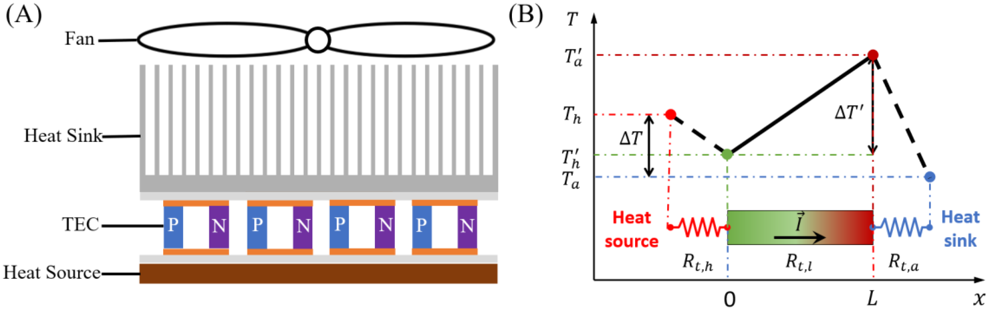
2.1. Theoretical Model Development

A.
Conventional heat dissipation system
We define a conventional heat dissipation system model, including heat sources, heat sinks, and thermal interface materials, as shown in Figure 1A. The conventional heat dissipation system’s thermal network and qualitative temperature allocation are illustrated in Figure 1B. Specifically, we denote the temperature and thermal resistance on the heat source side as T h and R t , h , respectively, while the corresponding values on the heat sink side are T a and R t , a . The temperature difference between these two sides is represented as Δ T .
Conventional heat dissipation methods primarily feature air and water cooling, which rely on conduction and convective heat transfer. The heat generated by the heat source is conducted to the extended surfaces (fins) of the heat sink and then dissipated into the surrounding air via natural or forced convective heat transfer. Conventional methods are deficient in their ability to control temperature effectively. This deficiency compels electronic devices to depend on passive heat dissipation strategies, hindering the realization of active thermal regulation and optimization within the heat dissipation process [30].
B.
Thermoelectric heat dissipation system
We define a thermoelectric heat dissipation system model that enhances conventional heat dissipation methods by integrating a thermoelectric module (TEC) between the heat source and the heat sink, as illustrated in Figure 2A. The thermal network and qualitative temperature allocation of the thermoelectric heat dissipation system are shown in Figure 2B.
The model defines critical parameters for temperature and thermal resistance.  T h represents the temperature at the heat source side, while the terminal temperatures of the thermoelectric leg are denoted as T h and T a . T a is the ambient temperature of the heat sink side. The temperature differences are defined as Δ T between the heat source side and heat sink side, and Δ T between the leg’s hot end and the heat sink side. The thermal resistances are represented as follows: R t , l for the TEC leg, R t , h for the heat source side, and R t , a for the heat sink side. R is the electrical thermal resistance of the TEC leg calculated by R = L / σ A .
When operating a thermoelectric heat dissipation system, the TEC’s cold end acts as a heat absorber for cooling purposes, while the hot end is tasked with heat expulsion through a heat sink. The heat sink’s thermal dissipation capacity is two-part, accounting for the heat drawn from the TEC and the Joule heat generated by the electric current flowing through the TEC [29]. This additional thermal load significantly raises the heat dissipation demands on the heat sink, thereby increasing the system’s overall thermal load. This increase can potentially limit the performance benefits of the thermoelectric system when compared to conventional heat dissipation methods.
In optimizing the maximum heat dissipation density of a thermoelectric heat dissipation system, the external heat transfer conditions can be expressed in terms of thermal resistance or as heat transfer coefficients based on the module’s substrate area A s , denoted as h h and h a . Accordingly, the thermal resistances at the heat source side and heat sink side are expressed as R t , h = 1 / h h A s and R t , a = 1 / h a A s , respectively. The thermal resistance of the thermoelectric module is given by R t , l = L / 2 N κ A , where L is the length of the leg, N is the number of thermoelectric couples, κ is the thermal conductivity, and A is the cross-sectional area.
The external thermal resistances are represented by the dimensionless thermal resistance parameters f h and f a . These parameters are as follows:
f h = R t , h R t , l = 2 N κ A h h A s L = κ h h L *
f a = R t , a R t , l = κ h a L *
The engineering leg length is given by L * = L / F F , where the fill factor FF is defined as 2 N A / A s .
This section derives the performance index formula for the thermoelectric heat dissipation system, starting from the thermal interface’s governing equations and heat balance conditions. For simplicity and clarity, the analysis focuses on a single thermoelectric cooler (TEC) leg, with the results readily extendable to modules comprising multiple legs. The material properties are assumed to remain constant and independent of temperature. Additionally, Equation (3) is derived under the assumption of a stationary state, ensuring its applicability to steady-state conditions.
κ d 2 T d x 2 + I 2 σ A 2 = 0 κ A d T d x + S T h I = T h T h f h R t , l , x = 0 κ A d T d x + S T a I = T a T a f a R t , l , x = L
The temperature allocation along the direction of the current can be derived from Equation (3), where the dimensionless current I * = S R t , l I .
T = 0.5 I 2 R R t , l L 2 x 2 + C 1 x + C 2 C 1 = 1 L 0.5 d 1 d 2 I 2 R R t , l + d 1 f a I 2 R R t , l Δ T + S R t , l I ( f h T a + f a T h ) f h + f a + d 1 d 2 C 2 = 1 d 1 f h [ 0.5 d 1 d 2 I 2 R R t , l + d 1 f a I 2 R R t , l Δ T + S R t , l I ( f h T a + f a T h ) ] f h + f a + d 1 d 2 + T h d 1 = 1 + f h I * d 2 = 1 f a I *
According to Equation (4), the terminal temperatures of the thermoelectric leg and the temperature difference between the leg’s hot end and the heat sink side are given by Equation (5).
T h = C 2 T a = 0.5 I 2 R R t , l + C 1 L + C 2 Δ T = I * 2 Z 1 [ d 1 f a 0.5 ( f h + f a ) ] Δ T + I * ( f h T a + f a T h ) f h + f a + d 1 d 2
Based on the above equations, the expressions for the heat dissipation power ( Q h ), input power ( P i n p u t ), and coefficient of performance (COP) of the thermoelectric heat dissipation system are derived as follows:
Q h = T h T h f h R t , l
= 1 Z R t , l 0.5 f a I * 3 0.5 1 + 2 f a ( 1 + Z T h ) I * 2 + Z T h I * + Z Δ T f h + f a + ( 1 + f h I * ) ( 1 f a I * )
P i n p u t = S Δ T I + I 2 R
= I * Z R t , l 0.5 ( f h f a ) I * 2 + I * [ 1 + f h + f a + Z ( f h T a + f a T h ) ] Z Δ T f h + f a + ( 1 + f h I * ) ( 1 f a I * )
C O P = Q h P i n p u t
= 1 I * 0.5 f a I * 3 0.5 1 + 2 f a ( 1 + Z T h ) I * 2 + Z T h I * + Z Δ T 0.5 ( f h f a ) I * 2 + I * [ 1 + f h + f a + Z ( f h T a + f a T h ) ] Z Δ T
Until now, various dimensionless parameters have been utilized to derive approximate analytical expressions for performance metrics. Building on this foundation, we will depart from the standard way of numerically solving the above equations and move on to analytical derivations.

2.2. Maximum Heat Dissipation Density

The expression for heat flux density in a conventional heat dissipation system is given as:
q h , c o m = h Δ T
where
h = h h h a h a + h h = h a 1 + r h
Δ T = T h T a
Similar to the derivation under cooling conditions in our previous research [24], we obtain a simple form of the optimum I * by ignoring the cubic term in the numerator and the whole denominator in the derivative of Q h with respect to I * as follows:
I q h , max * = Z T h 1 + 2 f a ( 1 + Z T h )
Substituting Equation (12) into Equation (6), the maximum heat dissipation power in the thermoelectric heat dissipation system is calculated by the following equation:
Q h , m a x = 0.5 α 1 Z T h 2 + α 2 Δ T α 3 R t , l
where we introduce three factors, that is,
α 1 = 1 + f a Z T h [ 1 + 2 f a ( 1 + Z T h ) ] 2
α 2 = 1 + 2 f a ( 1 + Z T h )
α 3 = ( 1 + 2 f a ) [ 1 + ( f h + f a ) ( 1 + Z T h ) ]
Practical heat transfer conditions should be considered by including the dimensionless thermal resistance parameter in the above factors. We can rewrite Equation (9) in its intensive forms, which are more convenient for further analyses.
q h , m a x = κ L * 0.5 α 1 Z T h 2 + α 2 Δ T α 3
Theoretical model calculations were performed near room temperature (300 K) using advanced thermoelectric (TE) materials characterized by the following parameters: Seebeck coefficient S = 200   μ V K 1 , electrical conductivity σ = 1 e 5   S m 1 , thermal conductivity κ = 1.5   m 1 K 1 , and figure of merit Z = 0.0026   K 1 . Our previous research [24] validated the high accuracies of the optimal dimensionless current and maximum cooling power density expressions under refrigerating modes. In the current study, the maximum heat dissipation power density was assessed, with an error margin within ±2%, achieving a comparable accuracy level, as shown in Figure 4A.
To verify the accuracy of the theoretical model, we incorporated the calculation parameters (Table 1) into the theoretical analysis model of this study based on Cai’s research [31], and calculated the maximum cooling capacity and current under two different thermal resistance conditions on the heat source side. By comparing the results with Cai’s research, the reliability of our work was verified, as shown in Figure 3. From the figure, it can be seen that the maximum cooling capacity and current of the two calculation results are in good agreement, indicating that the theoretical model proposed in this paper is reliable.
Figure 3. Comparison between the theoretical model calculation results of this study and the literature results under two different thermal resistance conditions: (A) Rt,h1 = 0.03823 K/W and (B) Rt,h2 = 0.15186 K/W.
Energies 18 00555 g003

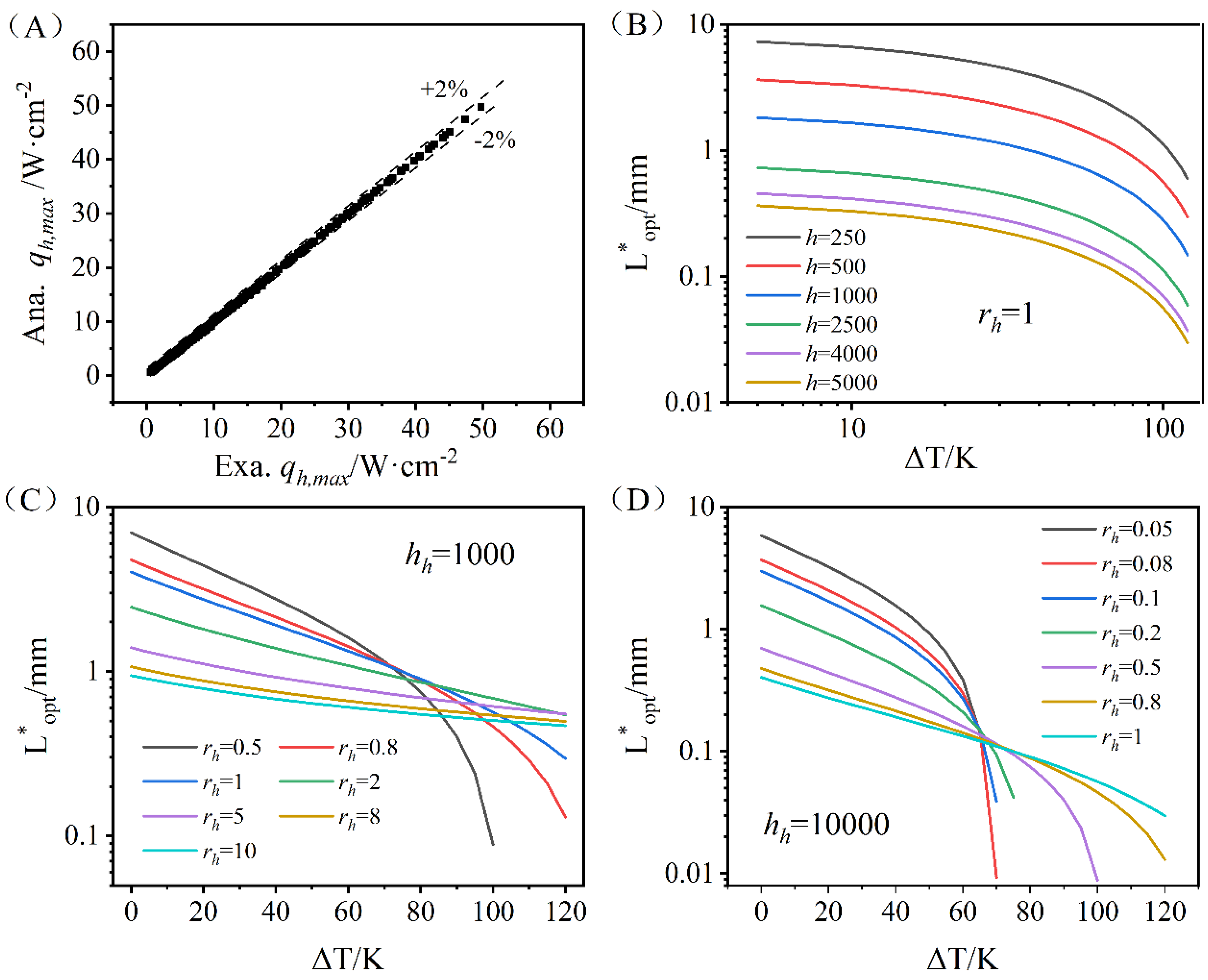
2.3. Optimal Engineering Leg Length

To facilitate the calculation of the optimal engineering leg length, we simplify the expression q h , m a x by defining Y = κ / L * . Additionally, r h represents the heat transfer allocation ratio. By setting d q h , m a x / d Y = 0 , the optimal engineering leg length L * is derived as follows:
L * = κ h a ϕ
where
ϕ = 1 + Z T h φ Z T a 1 + Z T h φ ( 1 + r h ) 2 Δ T T h 2 Δ T T h
r h = h a h h
φ = 0.5 Z T h + Δ T T h
In Equations (18) and (21), the heat transfer coefficient ranges from 500 to 10,000 W/m2 ·K on both the heat source and the heat sink sides, which can cover various scenarios, including natural air convection, forced convection, and even liquid–vapor phase change heat transfer.
The optimal engineering leg length selection depends on the system’s total heat transfer coefficient, as depicted in Figure 4. This coefficient integrates contributions from both the heat source and heat sink sides. The optimal leg length decreases with an increased total heat transfer coefficient. Specifically, when the heat transfer coefficient h h on the heat source side is fixed, an increase in the heat transfer allocation ratio r h (i.e., a higher heat transfer coefficient h a on the heat sink side) leads to a decrease in the optimal engineering leg length ( L * ). However, it is essential to note that the level of manufacturing technology has significant constraints on the engineering leg length. Currently, miniature thermoelectric modules (mini-TECs) with leg lengths as short as 0.2 mm are available on the market [32]. Therefore, achieving the desired precision may become challenging when the engineering leg length is below 0.1 mm [1].
Figure 4. (A) Validations of correlations of qh,max. (B) The optimal engineering leg length under different total heat transfer coefficients. (C) The optimal engineering leg length under different rh conditions when hh = 1000 W/m2·K. (D) The optimal engineering leg length under different rh conditions when hh = 10,000 W/m2·K.
Energies 18 00555 g004

2.4. Dimensionless Evaluation Index

We introduce a dimensionless evaluation index r q , defined as the ratio of the heat dissipation density of a conventional heat dissipation system to that of a thermoelectric heat dissipation system. When the dimensionless evaluation index satisfies r q < 0.9, the thermoelectric heat dissipation system is considered to have significant practical value when operating in its optimal state. However, as r q > 0.9, the performance advantage diminishes, making conventional systems more attractive, in consideration of the power consumption of the thermoelectric module as well as the more complicated system structure.
The maximum heat dissipation density of a thermoelectric heat dissipation system is expressed as follows:
q h , m a x = h ( β 1 Δ T + β 2 0.5 Z T h 2 )
where
β 1 = 1 + r h ϕ α 2 α 3
β 2 = 1 + r h ϕ α 1 α 3
We can approximately consider the maximum heat dissipation density as comprising two distinct components: the conductive term (the Δ T term) and the thermoelectric effect term (the Z T h 2 term). To investigate the impact of the conductive term on the total heat flux, we introduce the proportionality coefficient K, expressed as follows:
K = β 1 Δ T β 1 Δ T + β 2 0.5 Z T h 2
According to Equation (9), the heat dissipation density for a conventional heat dissipation system is expressed as follows:
q h , c o m = h Δ T
The dimensionless evaluation index ( r q ) is defined as follows:
r q = q h , c o m q h , m a x = Δ T β 1 Δ T + β 2 0.5 Z T h 2
Based on Equations (23), (24) and (26), it can be seen that r q , β 1 , and β 2 are functions of Z T a , r h , and Δ T . Among these parameters, Z T a can be determined, but further investigation is required for r h and Δ T . The parameter r h represents the heat transfer allocation ratio ( r h = h a / h h ). The heat transfer coefficient on the heat source side ( h h ) is primarily influenced by the combined effects of the ceramic plate, the copper strip, and the interface [19]. Consequently, an approximate range for h h can be derived, with h a being the critical variable.
Based on the above parameters, we can categorize the thermoelectric heat dissipation system into the following operating conditions:
(1)
When r h = 0 and Z T a can be determined, we define the dimensionless evaluation index r q as follows:
r q = f ( Δ T )
(2)
For finite values of h h , the heat dissipation density due to thermal conduction is given by the following equation:
q = h a 1 + r h Δ T
(3)
When h h is finite and both h a and r h , the maximum heat dissipation density can be expressed as follows:
q h , m a x = κ 0.5 Z T h 2 + Δ T L * + κ h h ( 1 + Z T h )

3. Results and Discussion

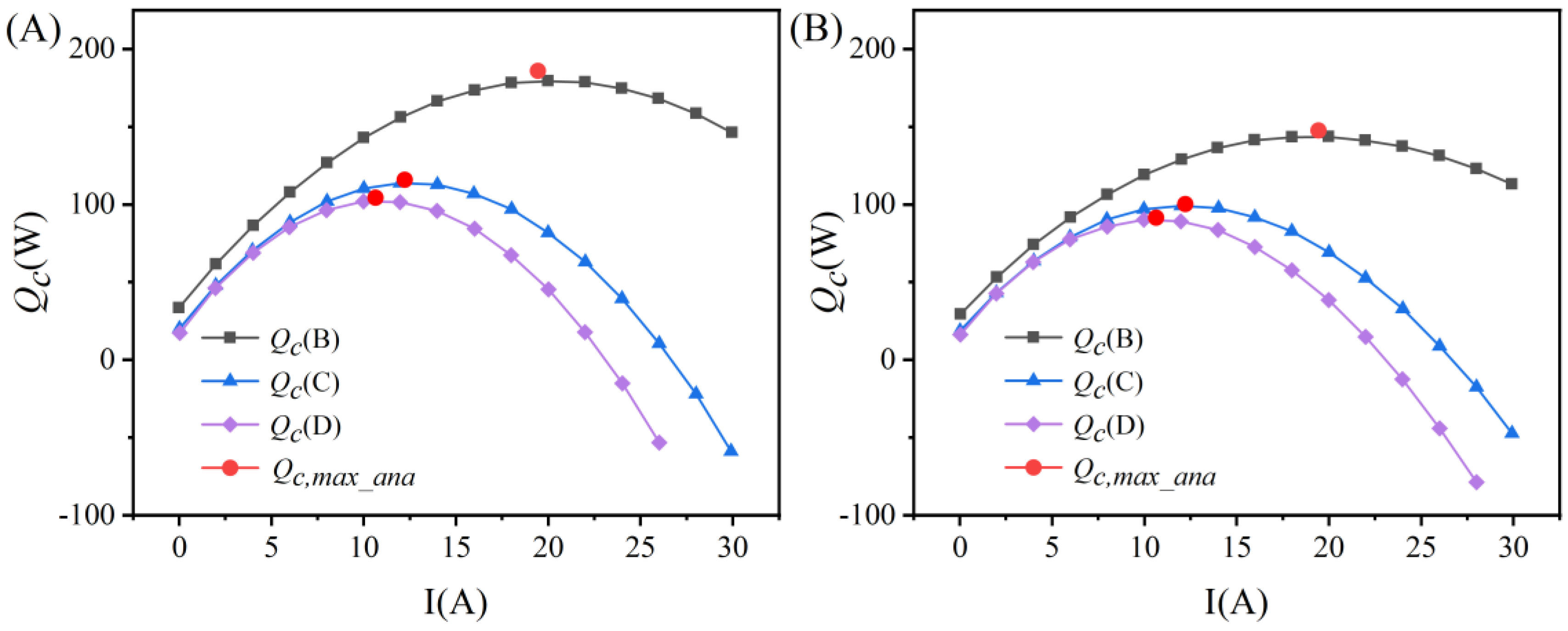
3.1. Maximum Heat Dissipation Density Analysis

According to Equation (22), the maximum heat dissipation density primarily comprises the conductive and thermoelectric effect terms. Figure 5 depicts the contour of the influencing parameters for the maximum heat dissipation density in a thermoelectric heat dissipation system. When the heat transfer allocation ratio ( r h ) is fixed, the parameter β 1 increases with rising temperature difference Δ T , while β 2 correspondingly declines. Conversely, for a fixed Δ T , an increase in r h results in a decrease in β 1 and an increase in β 2 . This indicates that the active part of the heat flux ( β 2 ) is sensitive to r h .
Additionally, the proportionality coefficient (K) increases with Δ T but decreases with r h . This demonstrates that as the temperature difference becomes larger, the conductive term gradually dominates, and the contribution of the thermoelectric effect weakens. Meanwhile, increasing r h reduces the influence of the conductive term while enhancing the thermoelectric effect.
In summary, the integration of thermoelectric modules into conventional heat sinks is constrained by certain temperature difference limitations. Furthermore, the heat transfer allocation ratio ( r h ) significantly impacts the performance of thermoelectric heat dissipation systems.

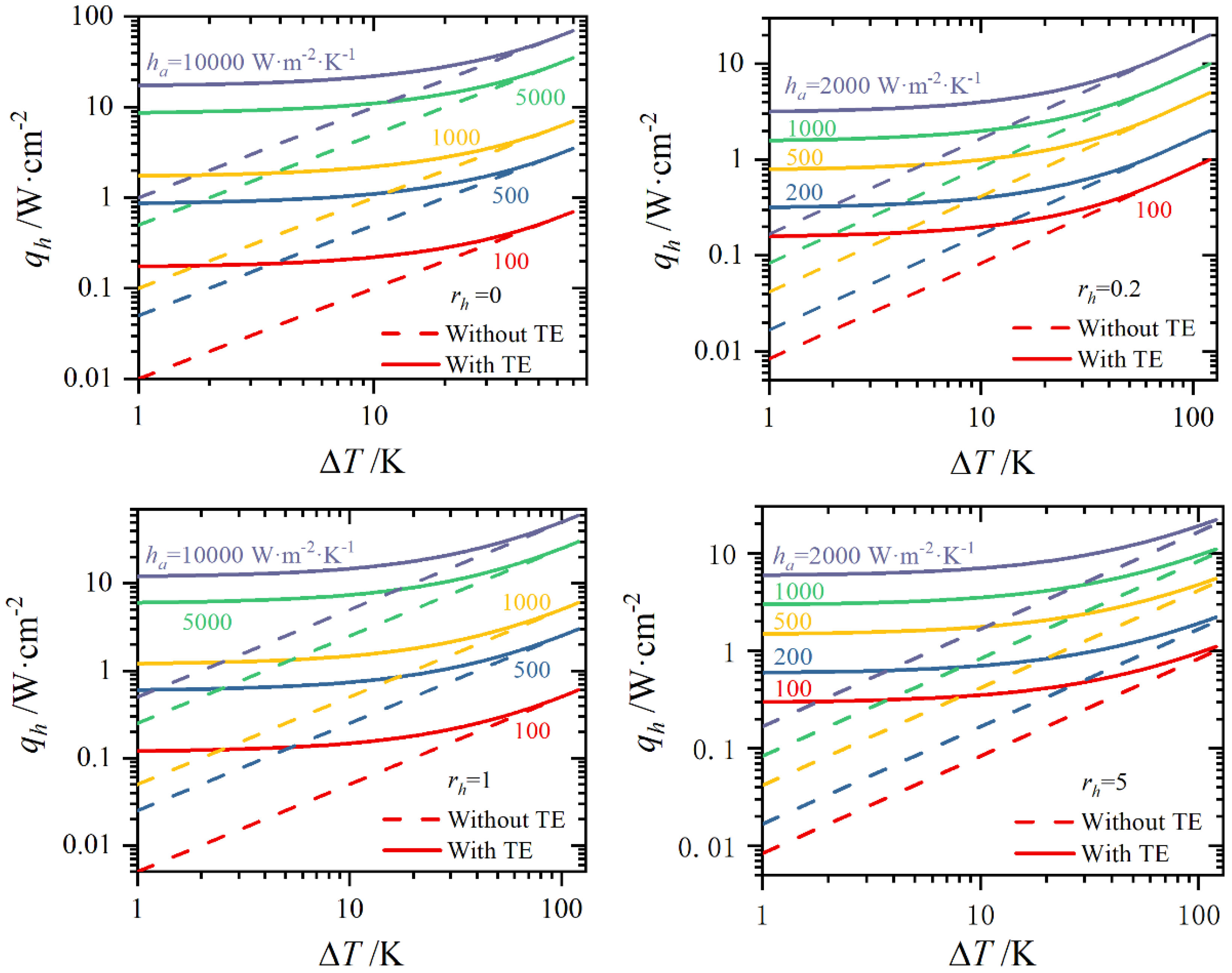
3.2. Heat Dissipation Density Under Different rh and ΔT

We analyzed the characteristics of the heat dissipation density distribution curves for both with TE and without TE, as shown in Figure 6. The heat dissipation density curve of conventional systems follows a linear relationship throughout. In contrast, the thermoelectric heat dissipation density is initially relatively insensitive to temperature differences. As the temperature difference increases, it gradually evolves into a linear relationship. This indicates the existence of a specific range where thermoelectric heat dissipation systems provide substantial performance. Furthermore, an increase in the heat sink side’s heat transfer coefficient leads to a corresponding rise in the maximum heat dissipation density, suggesting that enhancing the heat transfer coefficient on the heat sink side can effectively improve the performance of thermoelectric heat dissipation systems.

3.3. Dimensionless Evaluation Index Under Different rh and ΔT

The distribution characteristics of the dimensionless evaluation index r q under varying values of r h and Δ T are presented in Figure 5D and Figure 7A. It is essential to note that when r h < 0.9, the thermoelectric heat dissipation system is more attractive, with a corresponding temperature difference of 32 K, based on the performance of current thermoelectric (TE) materials.
Figure 5D demonstrates that, for small temperature differences ( Δ T < 32   K ) and a high heat transfer allocation ratio ( r h ), thermoelectric systems exhibit superior heat dissipation capabilities (upper left corner, r q < 0.9 ). This phenomenon is attributed to the active heat transfer driven by the Peltier effect, which is less reliant on temperature differences than conventional systems. Conversely, conventional systems rely on conduction or convection, making their performance heavily dependent on temperature gradients. At moderate temperature differences ( 32   K < Δ T < 60   K ) and a lower heat transfer allocation ratio ( r h ), the performance of the thermoelectric system advantage weakens, making conventional systems more attractive ( r q > 0.9 ). Therefore, a thermoelectric heat dissipation system is more suitable for heat dissipation scenarios with small temperature differences.
When r q = 0.9, a correlation between the temperature difference Δ T and r h is observed. Fixing the heat transfer coefficient on the heat source side while increasing r h enables thermoelectric systems to function effectively even under larger temperature differences (Figure 7A). Furthermore, Figure 5D illustrates that optimizing r h within the range 32   K < Δ T < 60   K can reduce the dimensionless evaluation index ( r q ). Thus, enhancing r h is critical to improving system performance under moderate temperature differences.
To further analyze the conditions that r h must be satisfied within the moderate temperature difference range, we set the dimensionless evaluation index r q to 0.9, thereby establishing the interrelationship between Δ T and r h , as shown in Figure 7B. The results indicate that the heat transfer allocation ratio ( r h ) must meet the condition r h 2.4 + 1.37 e 0.019 Δ T to ensure substantial heat dissipation performance.

4. Conclusions

In this work, a theoretical model for thermoelectric heat dissipation systems has been developed by incorporating the thermal resistance of the heat exchanger. Through analysis of the model, the optimal engineering leg length ( L * ) has been identified to maximize thermoelectric heat dissipation performance. Furthermore, a dimensionless evaluation index ( r q ) has been introduced to examine the effects of the temperature difference ( Δ T ) and heat transfer allocation ratio ( r h ) on system performance. Based on the current thermoelectric (TE) materials, the main conclusions calculated using theoretical models are as follows:
(1)
For a given heat source temperature, heat sink temperature, and external heat transfer conditions, an optimal engineering leg length ( L * ) exists that maximizes system heat dissipation. The selection of L * is strongly influenced by the system’s total heat transfer coefficient, decreasing as the coefficient increases. Enhancing the heat transfer coefficient on the heat sink side is critical for improving the performance of thermoelectric heat dissipation systems.
(2)
Thermoelectric heat dissipation systems demonstrate superior performance under small temperature differences ( Δ T < 32   K ). However, for moderate temperature differences ( 32   K < Δ T < 60   K ), substantial performance is achieved when r h 2.4 + 1.37 e 0.019 Δ T . This study provides theoretical guidance for designing and operating thermoelectric heat dissipation systems.

Author Contributions

Conceptualization, K.Z. and X.L.; methodology, X.L.; software, X.L.; validation, X.L. and R.S.; formal analysis, X.L.; investigation, K.Z.; resources, X.L.; data curation, X.L.; writing—original draft preparation, X.L.; writing—review and editing, K.Z.; visualization, X.L.; supervision, K.Z.; project administration, R.S.; funding acquisition, K.Z. All authors have read and agreed to the published version of the manuscript.

Funding

This research was funded by National Natural Science Foundation of China (NSFC), grant number No. 52202250.

Data Availability Statement

Data available on request due to restrictions eg privacy or ethical. The data presented in this study are available on request from the corresponding author. The data are not publicly available due to privacy.

Acknowledgments

This work is supported by the National Natural Science Foundation of China (NSFC) No. 52202250.

Conflicts of Interest

The authors declare no conflicts of interest.

Nomenclature

Nomenclature
qheat flux
SSeebeck coefficient
Zfigure of merit
Ttemperature
Lleg length
Aleg cross-section area
Assubstrate area
Qcheat dissipation power
Pelectric power
COPcoefficient of performance
rhheat transfer coefficient ratio
FFfill factor
L*engineering leg length
Nnumber of TE couples
I*dimensionless electric current
Rt,lleg thermal resistance
Rt, aheat sink side thermal resistance
Rt,hheat source side thermal resistance
hheat transfer coefficient
fdimensionless thermal resistance parameter
ΔTtemperature difference between the heat source and heat sink side
TEthermoelectric module
TECthermoelectric cooler
Greek Letters
σelectrical conductivity
κthermal conductivity
SUBSCRIPTS
maxmaximum point
optoptimal
comcommon
hheat source
aambient

References

  1. Zhang, Q.H.; Deng, K.F.; Wilkens, L.; Reith, H.; Nielsch, K. Micro-thermoelectric devices. Nat. Electron. 2022, 5, 333–347. [Google Scholar] [CrossRef]
  2. Zhang, H.Y.; Mui, Y.C.; Tarin, M. Analysis of thermoelectric cooler performance for high power electronic packages. Appl. Therm. Eng. 2010, 30, 561–568. [Google Scholar] [CrossRef]
  3. Sun, W.; Liu, W.-D.; Liu, Q.F.; Chen, Z.G. Advances in thermoelectric devices for localized cooling. Chem. Eng. J. 2022, 450, 138389. [Google Scholar] [CrossRef]
  4. Xu, Y.; Li, Z.J.; Wang, J.J.; Zhang, M.; Jia, M.; Wang, Q. Man-portable cooling garment with cold liquid circulation based on thermoelectric refrigeration. Appl. Therm. Eng. 2022, 200, 117730. [Google Scholar] [CrossRef]
  5. Zaferani, S.H.; Sams, M.W.; Ghomashchi, R.; Chen, Z.G. Thermoelectric coolers as thermal management systems for medical applications: Design, optimization, and advancement. Nano Energy 2021, 90, 106572. [Google Scholar] [CrossRef]
  6. Han, K.; Lou, Z.K.; Xi, X.M.; Cui, W.; Song, C. Low-temperature properties of the ytterbium-doped fiber laser cooled by the thermoelectric cooler. Opt. Fiber Technol. 2022, 73, 103036. [Google Scholar] [CrossRef]
  7. Sun, Y.T.; Zhou, L.; Meng, F.K.; Wang, Z. Performance analysis of four-stage thermoelectric cooler for focal plane infrared detectors. Int. J. Refrig. 2024, 165, 290–302. [Google Scholar] [CrossRef]
  8. Shen, L.M.; Pu, X.W.; Sun, Y.J.; Chen, J. A study on thermoelectric technology application in net zero energy buildings. Energy 2016, 113, 9–24. [Google Scholar] [CrossRef]
  9. Han, X.; Pang, M.; Teng, C.C.; Cao, M. Analysis and optimization of effect factors of refrigeration performance of portable micro-refrigerator. Appl. Therm. Eng. 2024, 246, 122948. [Google Scholar] [CrossRef]
  10. Elarusi, A.; Attar, A.; Lee, H. Optimal Design of a Thermoelectric Cooling/Heating System for Car Seat Climate Control (CSCC). J. Electron. Mater. 2016, 46, 1984–1995. [Google Scholar] [CrossRef]
  11. Lyu, Y.; Siddique, A.R.M.; Majid, S.H.; Biglarbegian, M.; Gadsden, S.A.; Mahmud, S. Electric vehicle battery thermal management system with thermoelectric cooling. Energy Rep. 2019, 5, 822–827. [Google Scholar] [CrossRef]
  12. Wu, H.; Shi, X.-L.; Duan, J.G.; Liu, Q.; Chen, Z.G. Advances in Ag2Se-based thermoelectrics from materials to applications. Energy Environ. Sci. 2023, 16, 1870–1906. [Google Scholar] [CrossRef]
  13. Scheele, M.; Oeschler, N.; Veremchuk, I.; Reinsberg, K.G.; Kreuziger, A.M.; Kornowski, A.; Broekaert, J.; Klinke, C.; Weller, H. ZT enhancement in solution-grown Sb(2-x)BixTe3 nanoplatelets. ACS Nano 2010, 4, 4283–4291. [Google Scholar] [CrossRef]
  14. Cao, Y.Q.; Zhao, X.B.; Zhu, T.J.; Zhang, X.B.; Tu, J.P. Syntheses and thermoelectric properties of Bi2Te3/Sb2Te3 bulk nanocomposites with laminated nanostructure. Appl. Phys. Lett. 2008, 92, 143106. [Google Scholar] [CrossRef]
  15. Crane, D.T.; Lorimer, A.; Hannemann, C.; Reifenberg, J.; Miller, L.; Scullin, M. A System-Level Approach to Thermoelectric Material Property Optimization. J. Electron. Mater. 2015, 44, 2113–2117. [Google Scholar] [CrossRef]
  16. Zhao, L.; Liu, D.; Feng, J.; Min, Y.; Li, J.; Ling, Y.; Li, H.; Zhao, D.; Liu, R.; Sun, R. Simultaneous optimization of cooling temperature difference and efficiency for multi-stage thermoelectric device. Appl. Energy 2024, 373, 123878. [Google Scholar] [CrossRef]
  17. Fabián-Mijangos, A.; Min, G.; Álvarez-Quintana, J. Enhanced performance thermoelectric module having asymmetrical legs. Energy Convers. Manag. 2017, 148, 1372–1381. [Google Scholar] [CrossRef]
  18. Huang, Y.-X.; Wang, X.-D.; Cheng, C.-H.; Lin, D.T.W. Geometry optimization of thermoelectric coolers using simplified conjugate-gradient method. Energy 2013, 59, 689–697. [Google Scholar] [CrossRef]
  19. Jeong, E.S. Optimization of thermoelectric modules for maximum cooling capacity. Cryogenics 2021, 114, 103241. [Google Scholar] [CrossRef]
  20. Pietrzyk, K.; Ohara, B.; Watson, T.; Gee, M.; Avalos, D.; Lee, H. Thermoelectric module design strategy for solid-state refrigeration. Energy 2016, 114, 823–832. [Google Scholar] [CrossRef]
  21. Wang, T.H.; Wang, Q.H.; Leng, C.; Wang, X.D. Parameter analysis and optimal design for two-stage thermoelectric cooler. Appl. Energy 2015, 154, 1–12. [Google Scholar] [CrossRef]
  22. He, Y.J.; Cao, C.; Wu, J.; Chen, G. Investigations on coupling between performance and external operational conditions for a semiconductor refrigeration system. Int. J. Refrig. 2020, 109, 172–179. [Google Scholar] [CrossRef]
  23. Venkatesan, K.; Venkata Ramanan, M. Design and performance evaluation of thermoelectric heat dissipation system integrated with PCM (phase change material). Int. J. Ambient. Energy 2022, 43, 8750–8762. [Google Scholar] [CrossRef]
  24. Zhu, K.; Deng, B.; Qian, X.; Wang, Y.; Li, H.; Jiang, P.; Yang, R.; Liu, W. A general White–Box strategy for designing thermoelectric heat dissipation system. InfoMat 2022, 4, e12324. [Google Scholar] [CrossRef]
  25. Muneeshwaran, M.; Tsai, M.-K.; Wang, C.-C. Heat transfer augmentation of natural convection heat sink through notched fin design. Int. Commun. Heat Mass Transf. 2023, 142, 106676. [Google Scholar] [CrossRef]
  26. Liu, Y.; Su, Y. Experimental investigations on COPs of thermoelectric module frosting systems with various hot side cooling methods. Appl. Therm. Eng. 2018, 144, 747–756. [Google Scholar] [CrossRef]
  27. Siahmargoi, M.; Rahbar, N.; Kargarsharifabad, H.; Sadati, S.E.; Asadi, A. An Experimental Study on the Performance Evaluation and Thermodynamic Modeling of a Thermoelectric Cooler Combined with Two Heatsinks. Sci. Rep. 2019, 9, 20336. [Google Scholar] [CrossRef]
  28. Astrain, D.; Aranguren, P.; Martínez, A.; Rodríguez, A.; Pérez, M.G. A comparative study of different heat exchange systems in a thermoelectric refrigerator and their influence on the efficiency. Appl. Therm. Eng. 2016, 103, 1289–1298. [Google Scholar] [CrossRef]
  29. Alzuguren, I.; Aranguren, P.; Casi, Á.; Erro, I.; Rodríguez, A. Thermoelectrics working in favor of the natural heat flow to actively control the heat dissipation. Int. Commun. Heat Mass Transf. 2024, 156, 107607. [Google Scholar] [CrossRef]
  30. Nair, V.; Baby, A.; Anoop, M.B.; Indrajith, S.; Murali, M.; Nair, M.B. A comprehensive review of air-cooled heat sinks for thermal management of electronic devices. Int. Commun. Heat Mass Transf. 2024, 159, 108055. [Google Scholar] [CrossRef]
  31. Cai, Y.; Liu, D.; Zhao, F.Y.; Tang, J.F. Performance analysis and assessment of thermoelectric micro cooler for electronic devices. Energy Convers. Manag. 2016, 124, 202–211. [Google Scholar] [CrossRef]
  32. Qiu, J.; Yan, Y.; Luo, T.; Tang, K.; Yao, L.; Zhang, J.; Zhang, M.; Su, X.; Tan, G.; Xie, H.; et al. 3D Printing of highly textured bulk thermoelectric materials: Mechanically robust BiSbTe alloys with superior performance. Energy Environ. Sci. 2019, 12, 3106–3117. [Google Scholar] [CrossRef]
Figure 1. (A) The conventional heat dissipation system model. (B) The thermal network and qualitative temperature allocation of the conventional heat dissipation system.
Energies 18 00555 g001
Figure 2. (A) The thermoelectric heat dissipation system model. (B) Thermal network and qualitative temperature allocation of thermoelectric heat dissipation system.
Energies 18 00555 g002
Figure 5. The contour of influencing parameters (A) β 1 ; (B) β 2 ; (C) K; (D) rq.
Energies 18 00555 g005
Figure 6. The distribution curve of heat dissipation density for both with TE and without TE.
Energies 18 00555 g006
Figure 7. (A) Dimensionless evaluation index (rq) under different rh and ΔT. (B) The relationship between rh and Δ T under rq = 0.9.
Energies 18 00555 g007
Table 1. List of different TECs with their supplied data and calculated module parameters.
TypeZ (1/K)S (V/K)Rt,h1 (K/W)Rt,h2 (K/W)Rt,m (K/W)Rt,a (K/W)
TB-127-2.0-1.15(B)0.002570.05230.038230.151860.64580.04684
TEC2-12712(C)0.002590.05070.038230.151861.17910.04684
TB-127-1.4-1.05(D)0.002580.05230.038230.151861.32730.04684
Disclaimer/Publisher’s Note: The statements, opinions and data contained in all publications are solely those of the individual author(s) and contributor(s) and not of MDPI and/or the editor(s). MDPI and/or the editor(s) disclaim responsibility for any injury to people or property resulting from any ideas, methods, instructions or products referred to in the content.

