Review

Research and Application of Oxygen-Reduced-Air-Assisted Gravity Drainage for Enhanced Oil Recovery

1
University of Chinese Academy of Sciences, Beijing 101400, China
2
Institute of Porous Flow and Fluid Mechanics, Chinese Academy of Sciences, Langfang 065007, China
3
National Key Laboratory of Enhanced Oil and Gas Recovery, Beijing 100083, China
4
China National Petroleum Corporation, Beijing 100007, China
5
PetroChina Huabei Oilfield Company, Renqiu 062550, China
*
Author to whom correspondence should be addressed.
Energies 2025, 18(3), 557; https://doi.org/10.3390/en18030557
Submission received: 19 December 2024 / Revised: 16 January 2025 / Accepted: 21 January 2025 / Published: 24 January 2025
(This article belongs to the Special Issue Petroleum and Natural Gas Engineering)

Abstract

:
This paper summarizes the research progress and applications of oxygen-reduced-air-assisted gravity drainage (OAGD) in enhanced oil recovery (EOR). The fundamental principles and key technologies of OAGD are introduced, along with a review of domestic and international field trials. Factors influencing displacement performance, including low-temperature oxidation reactions, injection rates, and reservoir dip angles, are discussed in detail. The findings reveal that low-temperature oxidation significantly improves the recovery efficiency through the dynamic balance of light hydrocarbon volatilization and fuel deposition, coupled with the synergistic optimization of the reservoir temperature, pressure, and oxygen concentration. Proper control of the injection rate stabilizes the oil–gas interface, expands the swept volume, and delays gas channeling. High-dip reservoirs, benefiting from enhanced gravity segregation, demonstrate superior displacement efficiency. Finally, the paper highlights future directions, including the optimization of injection parameters, deepening studies on reservoir chemical reaction mechanisms, and integrating intelligent gas injection technologies to enhance the effectiveness and economic viability of OAGD in complex reservoirs.

1. Introduction

With the continuous growth of the global energy demand, conventional oilfields are progressively transitioning into high water-cut development stages, significantly increasing the difficulty of recovering residual oil. Consequently, oilfield development is facing increasingly severe challenges [1,2,3]. Against this backdrop, enhanced oil recovery (EOR) technologies have become a critical research focus in the field of oilfield development [4,5,6]. Gas-assisted gravity drainage (GAGD), as an advanced EOR technology, leveraging gravity segregation effects, has gained significant attention due to its ability to utilize the density difference between gas and crude oil to expand the swept volume and enhance the displacement efficiency. Among these, OAGD technology has demonstrated promising potential, particularly in reducing oxidation risks, delaying gas channeling, and stabilizing gas drive fronts. This technology shows broad application prospects, especially in low-permeability, ultra-low-permeability, and complex reservoirs, where it exhibits remarkable oil recovery potential [7].
Compared to conventional water flooding, oxygen-reduced air gravity drainage demonstrates significant advantages in expanding sweep efficiency and enhancing gas flooding stability. However, the diverse and complex nature of reservoir conditions presents numerous challenges for its practical application. Key issues include optimizing the injection rates and oxygen concentrations to delay gas channeling and maximize the recovery efficiency, clarifying the mechanisms of chemical interactions between oxygen-reduced air, reservoir minerals, and crude oil and their impact on reservoir stability, and developing effective injection production strategies tailored to heterogeneous reservoirs. Addressing these challenges remains critical for advancing this technology.
In recent years, researchers both domestically and internationally have conducted extensive studies on OAGD technology. These studies have focused on various aspects, including the mechanisms of LTO reactions and the optimization of gas injection parameters, gas migration patterns, and oil–gas interface stability. Laboratory-scale physical simulations and numerical modeling have unveiled the dynamic changes of the oil–gas interface during gas injection and identified key influencing factors. Field trials have further validated the feasibility of this technology in low-permeability reservoirs, high-dip reservoirs, and heavy oil reservoirs [8]. However, these studies still exhibit notable limitations, particularly in the investigation of multi-factor synergistic effects under complex reservoir conditions, the impact of reservoir heterogeneity on oil recovery efficiency, and the optimization of injection production strategies for engineering applications. Further exploration is required in these areas.
This paper provides a systematic review of the research status of this technology, focusing on its fundamental principles, key techniques, and influencing factors. It further addresses existing scientific issues and engineering challenges, proposing future research directions and development recommendations to offer theoretical insights and technical guidance for the advancement of oxygen-reduced air gravity drainage technology and its application in practical reservoir development (Figure 1).

2. OAGD

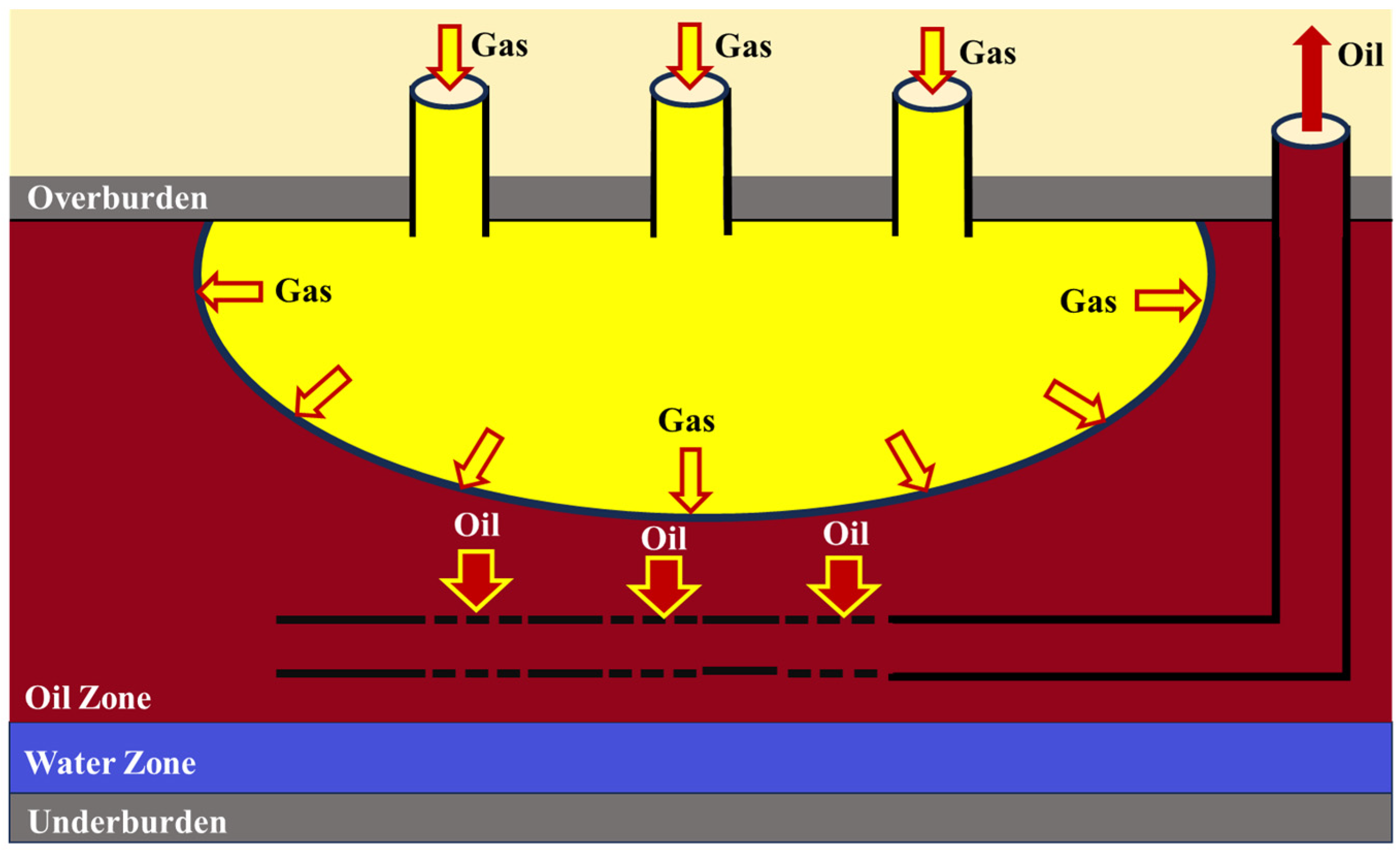
2.1. Fundamental Principles of Oxygen-Reduced Air Gravity Drainage

OAGD combines the principles of oxygen-reduced air injection with gas-assisted gravity drainage (GAGD). Compared to traditional water flooding techniques, GAGD leverages the density difference between gas and crude oil to effectively mobilize residual oil under the influence of gravity. This method is particularly suitable for high-angle, thick, or complex heterogeneous reservoirs where conventional technologies struggle to achieve sufficient coverage and recovery [9,10,11]. The core advantage of this technology lies in its ability to fully utilize gravity segregation effects. The injected gas diffuses upward within the reservoir, causing crude oil to flow downward under gravitational forces toward the production well, thereby significantly enhancing the vertical displacement efficiency (Figure 2). This displacement method prevents water breakthrough and channeling issues commonly encountered in water flooding processes, effectively expanding the swept volume and mobilizing a greater proportion of residual oil [12].
The selection of oxygen-reduced air as the medium for oxygen-reduced-air-assisted gravity drainage is primarily based on its safety, economic feasibility, and EOR efficiency. Compared to conventional air injection techniques, oxygen-reduced air reduces the oxygen content, effectively mitigating the explosion risks associated with oxidation reactions while retaining the critical displacement efficiency characteristics of air injection [13,14]. This refinement not only enhances the controllability of the technology but also expands its applicability in complex reservoir conditions. Its core advantage lies in combining LTO reactions with gravity segregation effects to improve oil recovery. During the displacement process, LTO generates flue gases (such as CO2 and water vapor), which further increase the swept volume, reduce crude oil viscosity, and elevate the reservoir temperature, thereby enhancing the oil recovery efficiency [15,16,17]. Compared to conventional water flooding or other gas displacement methods, oxygen-reduced air flooding demonstrates exceptional performance in high-dip, low-permeability reservoirs. It effectively mobilizes residual oil and delays gas breakthrough, significantly improving the recovery efficiency [18,19,20].

2.2. Oxygen-Reduced Air Preparation Technologies

In terms of resources and cost effectiveness, oxygen-reduced air offers inherent advantages. Its production relies on well-established technologies, such as pressure swing adsorption (PSA), membrane separation, and cryogenic separation, ensuring low costs and abundant gas supply. This makes it particularly suitable for oilfield development projects with high economic requirements. Compared to nitrogen or carbon dioxide flooding, the acquisition and preparation of oxygen-reduced air are more convenient while maintaining significant oil recovery efficiency and operational safety [21]. Therefore, oxygen-reduced air has emerged as an ideal displacement medium for gas-assisted gravity drainage, making it a preferred choice for EOR during the later stages of oilfield development.

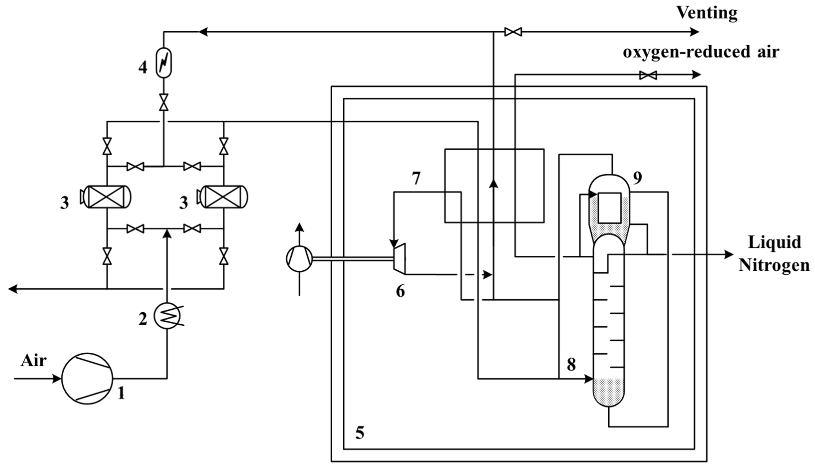
2.2.1. Cryogenic Separation

Cryogenic separation involves a series of purification, compression, and cooling processes, where air is passed through a primary heat exchanger to achieve liquefaction, forming liquid air. The liquid air is then introduced into a distillation column for separation, utilizing the differing boiling points of oxygen and nitrogen. Oxygen, with its higher boiling point, gradually accumulates at the lower section of the distillation column, forming oxygen-enriched liquid air. Meanwhile, oxygen-reduced air can be obtained from the upper section of the column as required [22]. The typical process of cryogenic separation is illustrated in Figure 3.

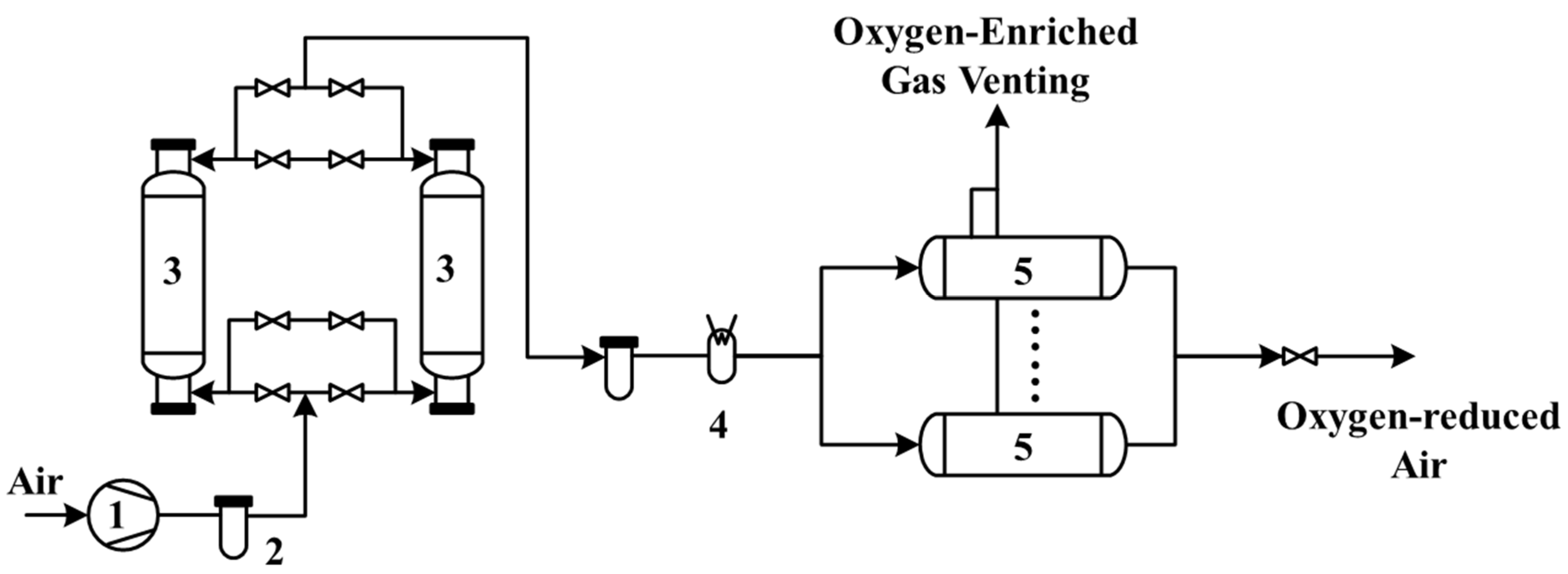
2.2.2. Membrane Separation Method

The core of membrane separation technology lies in the selection of membrane materials. For specific membrane materials, nitrogen and oxygen in the air exhibit significant differences in solubility and diffusion rates, particularly under higher pressure conditions. By utilizing the pressure differential across the membrane, faster-diffusing gases such as water vapor and oxygen preferentially pass through to the low-pressure side, forming oxygen-enriched gas, while slower-diffusing nitrogen accumulates on the high-pressure side, thereby achieving the separation of oxygen-reduced air [23]. The process flow of the membrane separation method is shown in Figure 4.

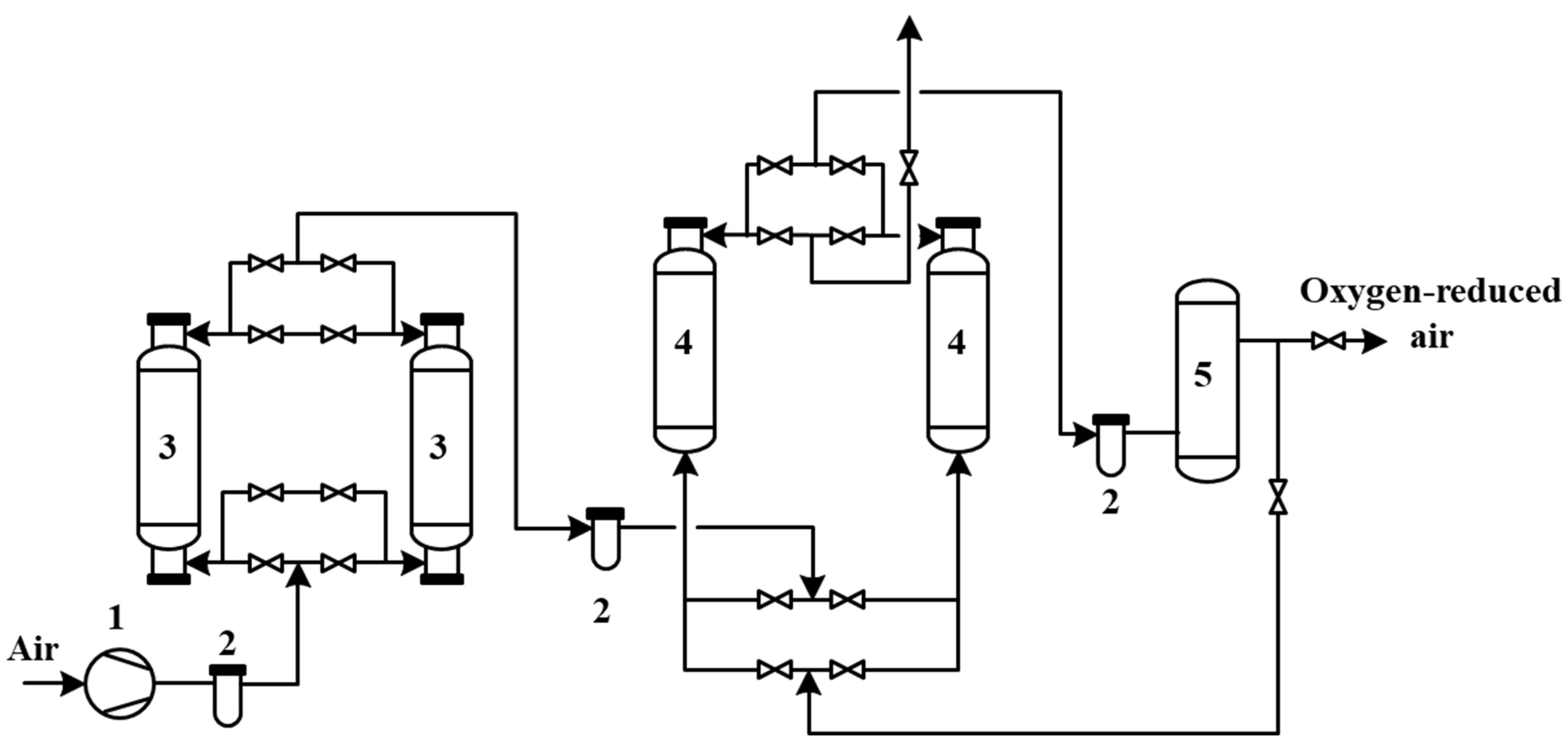
2.2.3. Pressure Swing Adsorption (PSA) Technology

PSA technology is a separation process based on the adsorption phenomenon. It utilizes porous solid media in contact with gas or liquid phases to selectively adsorb specific components from the fluid on the solid surface, thereby achieving separation and enrichment of the desired components [24]. This technology adjusts the pressure during the adsorption and desorption processes, significantly altering the composition and concentration of the fluid’s components [25]. The entire PSA nitrogen production process can be divided into four sub-processes: pressurized adsorption, pressure maintenance, depressurization regeneration, and purging [22,26,27]. The classic PSA process flow is shown in Figure 5.

2.2.4. Comparison of Oxygen-Reduced Air Preparation Processes

In oilfield applications requiring nitrogen, the nitrogen purity in oxygen-reduced air must be maintained at 90–95% to ensure safety. The PSA (pressure swing adsorption) process offers significant economic advantages with lower equipment investment costs, being particularly suited for medium-purity nitrogen requirements. Compared to cryogenic separation, PSA does not require operation at low temperatures, simplifying the process flow, reducing equipment investment and operating costs, and greatly enhancing economic efficiency (Table 1).
Furthermore, PSA technology’s rapid start-up and shutdown capabilities make it well suited to fluctuating demands for oxygen-reduced air in oilfields, accommodating frequent start–stop operations. In contrast, cryogenic separation, with longer start-up and shutdown times, is less flexible and unsuitable for the dynamic needs of oilfields. Additionally, PSA is simple to operate, requires minimal maintenance, and can achieve long-term, low-cost, and stable operation in the complex environments of oilfields.

2.3. Field Trials in China and Internationally

2.3.1. International Field Trials

Air injection technology has progressed internationally since its first trial in 1963, demonstrating significant production increases. By 1996, it had achieved large-scale application, with recovery rates improving from 6% to over 30% (Table 2). This evolution validated its enhanced oil recovery potential, refined the approach through optimization, and facilitated its global adoption.
In 1965, gravity-stable displacement trials in the United States laid the foundation for subsequent developments. By 1975, gas injection enhanced the recovery efficiency in the Hawkins Field. In 1992, gravity-stable displacement effectiveness was validated in Hungarian oilfields. In 1997, Indonesia’s oilfields achieved a recovery rate of 59.2%. By 2000, the Cantarell Field successfully stabilized the oil–gas interface and boosted production, marking the maturity and widespread adoption of the technology (Table 3).

2.3.2. Field Trials in China

In recent years, air injection technology has seen significant advancements in China. Trials conducted in oilfields such as Zhejiang and Jilin have demonstrated great potential. The Baise Oilfield achieved a cumulative production increase of 14,800 tons, and the Tuha Oilfield improved recovery rates by 10–20%. Moreover, oilfields in Zhongyuan, Liaohe, Zhejiang, and Jilin reported increased production and reduced water cuts, underscoring the potential for broader application of this technology (Table 4).
Top gas injection technology in China is still in its exploratory phase. In 1994, the Yanling Oilfield conducted the first trial; in 2007, the Weizhou Oilfield optimized injection production well patterns; in 2015, the Huabei Oilfield achieved a recovery increase of over 10%; and in 2024, the Qinghai Oilfield enhanced the stability of gas drive, further improving the gravity-stable gas injection efficiency (Table 5).

3. Key Factors Influencing OAGD

3.1. LTO

The LTO process of oxygen-reduced air gravity drainage is a critical mechanism for EOR. It is influenced by multiple factors, including the segmentation of oxidation stages, regulation of oxygen concentration, characteristics of oxidation product formation, and experimental methodologies. Simultaneously, experimental studies and numerical modeling provide theoretical support for elucidating the reaction pathways and oil recovery mechanisms of LTO. Future research should focus on the coupling effects of the reservoir temperature, pressure, and oxygen concentration on LTO efficiency. An in-depth exploration of its dynamic effects and application potential is essential to optimize technical parameters and improve the stability and feasibility of oil recovery.
The LTO process of crude oil can be divided into four stages: light hydrocarbon evaporation, low-temperature oxidation, fuel deposition, and high-temperature oxidation [45,46]. Among these, the LTO stage, due to its lowest activation energy, is the most likely phase for crude oil oxidation reactions to occur. During this stage, the oxidation process generates heat and flue gases (such as CO2 and water vapor), which help reduce crude oil viscosity and increase the reservoir temperature. As the temperature rises, the oxidation reaction rate accelerates; however, excessively high temperatures may lead to saturation of the oil recovery effect [47,48]. Therefore, it is essential to optimize the oil displacement conditions based on reservoir temperature to balance oxidation efficiency and operational safety.
Oxygen concentration plays a decisive role in the LTO process of crude oil. Higher oxygen concentrations can intensify the oxidation reaction but may also result in pore blockage and safety risks. In oxygen-reduced air flooding, controlling the oxygen concentration enables the achievement of optimal LTO efficiency while ensuring the safety of the gas injection process (Figure 6) [18]. An appropriate oxygen concentration can also delay gas breakthrough, optimize gas flow pathways, enhance sweep efficiency, and improve oil recovery performance [49].
The products of LTO reactions include heat, flue gases such as CO2, CO, and CH4, as well as partial oxidation derivatives such as alcohols, ketones, and organic acids [17,46,48]. These products not only help reduce crude oil viscosity and oil–water interfacial tension but also enhance oil recovery efficiency through gas miscibility and oil expansion. Furthermore, the generated flue gases contribute to maintaining reservoir pressure and delaying gas breakthrough [50]. However, heavy components formed during the oxidation process may deposit locally, impairing the reservoir’s permeability and flow capacity, which necessitates effective control measures [51].
Common methods for studying the LTO process include thermogravimetric analysis (TGA), differential scanning calorimetry (DSC), gas chromatography (GC), and Fourier-transform ion cyclotron resonance mass spectrometry (FT-ICR-MS). These techniques are instrumental in revealing heat release, compositional changes, and reaction pathways during the oxidation process [52,53]. In porous media, static and dynamic oxidation experiments combined with kinetic models can be employed to investigate reaction behaviors under varying temperatures, pressures, and oxygen concentrations. These studies facilitate the optimization of injection parameters for oxygen-reduced air flooding.
The reaction pathways of LTO are primarily determined by the reservoir temperature, pressure, and oxygen concentration [20,36]. At temperatures below 120 °C, the reaction products are predominantly oxygenated derivatives. As the temperature increases, fuel deposition and high-temperature combustion gradually become dominant processes (Figure 7) [54,55]. Studies have shown that appropriate oxidation conditions not only improve crude oil mobility but also optimize gas flow pathways through self-correction effects, further expanding the sweep area and enhancing the oil recovery efficiency [56].

3.2. Injection Rate

By carefully designing the injection rate, it is possible to stabilize the oil–gas interface, optimize the displacement efficiency, and meet the requirements of various reservoir conditions. Numerical simulations and experimental studies provide theoretical and practical support for optimizing injection rates, with a focus on balancing the injection production rates, sweep efficiency, and economic benefits.
Proper control of the gas injection rate is crucial for maintaining the stability of the oil–gas interface. Lower injection rates can help establish a stable oil–gas interface, slow the downward movement of the interface, and prevent the occurrence of viscous fingering [57,58]. However, excessively high injection rates can compromise interface stability, accelerating the movement of the gas front and causing gas channeling, which reduces the oil recovery efficiency. This issue is particularly pronounced under miscible displacement conditions (Figure 8) [10,59,60].
Determining the optimal range of injection rates is equally important, as oil recovery typically exhibits a trend of initially increasing and then decreasing with the injection rate [61]. Studies have shown that appropriately reducing the injection rate can decrease residual oil saturation, increase the gas swept volume, and enhance oil recovery [62]. However, excessively low injection rates may lead to insufficient viscous force and capillary trapping, prolonging the breakthrough time and impacting economic efficiency. Conversely, excessively high injection rates can exacerbate gas breakthrough, resulting in a decline in oil recovery (Figure 9) [10].
The design of injection rates must consider reservoir characteristics and the specific stage of displacement. In low-permeability reservoirs, lower injection rates can prevent rapid gas breakthrough and uneven flow. In contrast, in high-permeability reservoirs or light oil reservoirs, moderately higher injection rates can enhance the displacement efficiency, provided they do not compromise interface stability due to excessive rates [63,64,65]. In addition, factors such as the reservoir temperature, pressure, and oxygen concentration significantly influence the optimal range of injection rates. These parameters must be carefully balanced to achieve effective displacement and maintain reservoir stability.
Through numerical simulation and experimental analysis, the optimization of injection rate parameters can be effectively achieved. Studies have demonstrated that lower injection rates not only enhance oil recovery but also expand the gas swept volume and maintain reservoir pressure more effectively [66]. In experiments conducted in the Qinghai Oilfield, oxygen-reduced air demonstrated significant LTO effects at a moderate injection rate, leading to improved ultimate oil recovery. Similarly, studies in the Honghe Oilfield revealed that optimized injection rates and oxygen concentrations enhanced the oil displacement efficiency. Furthermore, numerical simulations indicate that the impact of the injection rate on the oil recovery efficiency is closely tied to the balance among gravity, viscous forces, and capillary forces. Experimental calibration of the model parameters is essential to achieve optimal displacement performance (Figure 10 and Figure 11) [67,68].

3.3. Reservoir Inclination

Reservoir inclination is a critical factor in OAGD. High-inclination reservoirs enhance gravity segregation, resulting in a more stable gas cap for oil displacement, reduced gas channeling, and significantly improved oil recovery rates. In practical applications, it is essential to prioritize the evaluation of reservoir inclination and associated geological conditions. Optimizing well placement and gas injection parameters is key to leveraging the advantages of reservoir inclination effectively [61].
In high-inclination reservoirs, gas naturally migrates upward due to its lower density, forming a gas cap. This gas cap utilizes the density contrast between gas and crude oil to drive the oil–gas interface downward, effectively displacing residual oil located at the top and near faulted areas, commonly referred to as “attic oil” [69,70,71]. As the reservoir dip angle increases, the gravitational differentiation effect becomes more pronounced, significantly enhancing the stability of the oil–gas interface, reducing viscous fingering, and expanding the swept volume, thereby improving recovery efficiency. In reservoirs with smaller dip angles, gas tends to break through the oil zone, leading to gas channeling and reduced displacement efficiency. In contrast, larger dip angles allow gas to accumulate more effectively at the reservoir top, delaying the onset of gas channeling.
Experimental and numerical simulations indicate that the reservoir dip angle has a direct impact on displacement efficiency. As the dip angle increases, the gravitational force component becomes more pronounced, significantly EOR efficiency. The data in Table 6 show that as the dip angle increases from 0° to 80°, the ultimate recovery factor improves from 31.87% to 55.64%, representing a significant increase of 23.77% [72]. In addition, the gas displacement front in high-dip reservoirs is more stable, facilitating the accumulation of residual oil at the front to form an oil bank. This enhances the displacement efficiency, extends the displacement duration, and expands the sweep area [73].
In high-dip reservoirs, a greater reservoir dip angle corresponds to a higher gravitational stability number (e.g., Non-Dimensional Gravity-Assisted Gravity Index (NGAGI)), which promotes the formation of a stable oil–gas interface [62]. Studies indicate that when the reservoir dip angle reaches 13.8°, the gravitational stability number exceeds 1, signifying that the gas injection process can achieve stable gravity-driven oil recovery. Enhanced gravitational stability models further demonstrate that an increased dip angle not only improves the efficiency of gas migration to the reservoir top but also reduces the residual oil saturation at the top, thereby enhancing displacement stability and recovery efficiency [74].
In the practical application of oxygen-reduced air injection, the advantages of high-dip reservoirs have been validated through experiments and numerical simulations [45,46]. For example, in the Weizhou Oilfield experiment, arranging injection wells at the top of the reservoir and production wells at the bottom enabled gravity-stabilized gas flooding, which ultimately enhanced the recovery factor [62]. Meanwhile, studies have also shown that reservoir dip angle and injection rate are the most critical factors influencing oil recovery efficiency. Parameters such as the production rate, vertical-to-horizontal permeability ratio, and crude oil viscosity significantly impact efficiency, whereas capillary pressure and reservoir heterogeneity have relatively minor effects.

3.4. Reservoir Types

The applicability of oxygen-reduced-air-assisted gravity drainage (OAGD) largely depends on the geological and fluid properties of the reservoir. Studies indicate that reservoirs with moderate to steep dip angles (5–36°) are most suitable for OAGD [61]. These reservoirs significantly enhance gravity segregation, stabilizing the oil–gas interface during gas injection. For instance, the Weeks Island Reservoir (26° dip angle) and Bay St. Elaine Reservoir (36° dip angle) demonstrate strong gas accumulation capabilities, delaying gas breakthrough and improving recovery efficiency. This highlights the critical role of dip angles in gas distribution and displacement stability, where overly low angles may weaken gravity segregation, and excessively high angles could lead to uneven gas flow.
Reservoir thickness is another crucial factor influencing the sweep efficiency and stability of the injection front. OAGD technology performs exceptionally well in reservoirs with thicknesses ranging from 15 to 290 m. For example, the Wizard Lake Reservoir [75] (198 m thick) showcases the advantages of thick reservoirs for displacement, while the Handil Main Reservoir [76] (15–25 m thick) demonstrates that medium-thickness reservoirs can also achieve significant recovery improvements with optimized injection production strategies. However, thinner reservoirs may face limitations in sweep efficiency, requiring adjustments in their injection rates and gas distribution paths to maximize effectiveness.
Permeability plays a decisive role in determining the efficiency of gas flow and oil displacement. OAGD technology has been successfully applied across a wide permeability range from 10 to 3400 mD. High-permeability reservoirs like the Hawkins Dexter Reservoir (3400 mD) exhibit excellent gas flow performance, while low-permeability reservoirs such as the Donghe 1 Reservoir [77] (60 mD) have achieved notable recovery improvements through optimized injection parameters. Nevertheless, gas flow resistance in low-permeability reservoirs necessitates careful regulation of the injection pressure and oxygen concentration, while high-permeability reservoirs require measures to prevent gas channeling.
The viscosity and density of crude oil directly impact the efficiency of OAGD. Research shows that low- to medium-viscosity oils (viscosity below 50 mPa·s) are better suited for gravity-driven segregation processes, while lower-density oils (API gravity above 25°) enhance gas displacement and viscosity reduction effects. These fluid characteristics make OAGD particularly advantageous in low-permeability and complex reservoirs. For high-viscosity oils, additional measures such as thermal recovery or chemical modification may be needed to enhance applicability.
Reservoir lithology is another critical factor for the successful application of OAGD. Both sandstone and carbonate reservoirs exhibit good adaptability. Sandstone reservoirs (e.g., Weeks Island and Donghe 1) typically offer higher gas permeability, whereas carbonate reservoirs (e.g., Westpem Nisku) excel under steep dip angles due to their fracture development, providing superior gravity-driven displacement. However, fractures may also lead to premature gas breakthrough, requiring optimized injection production designs for mitigation.
In summary, OAGD is well suited for reservoirs with moderate to steep dip angles, significant thickness, medium to high permeability, and low- to medium-viscosity and -density oils. By aligning reservoir characteristics with injection production strategies, such as adjusting the injection rates, optimizing the oxygen concentration, and controlling the injection pressure, the efficiency and adaptability of OAGD can be further enhanced. This provides a robust theoretical foundation and practical guidance for its application in complex reservoir conditions.

4. Conclusions and Outlook

4.1. Challenges

1. While extensively studied, LTO in OAGD faces critical challenges. Current research predominantly examines single-factor effects, such as temperature, oxygen concentration, and pressure, under idealized laboratory conditions. This approach limits the understanding of dynamic coupling mechanisms in complex reservoirs, leading to discrepancies between experimental results and field applications. Key issues include the insufficient exploration of the combined effects of reservoir heterogeneity, rock wettability, and pressure variations on LTO reactions and gas transport. Furthermore, the impact of oxidation byproducts, such as heavy component deposition causing pore blockage and permeability reduction, is poorly understood. Long-term gas injection studies remain underdeveloped, with inadequate insights into reservoir temperature, oxygen concentration, and reaction rate dynamics.
2. The injection rate significantly influences oil–gas interface stability, sweep efficiency, and recovery. However, challenges persist in understanding multi-factorial effects, including reservoir heterogeneity, temperature, pressure, and the oxygen concentration. Most studies focus on initial stages, overlooking temporal variations in injection rates and their impact on reservoir pressure distribution and fluid flow. Additionally, field validation of injection production strategies is limited, particularly in complex reservoir conditions.
3. High dip angles improve gravity segregation, stabilize gas caps, and enhance recovery efficiency. However, existing research focuses on homogeneous reservoirs, neglecting the effects of fractures, connectivity, and permeability contrasts in heterogeneous systems. The interplay between the dip angle and injection rate is poorly understood, and long-term oil–gas interface stability remains inadequately analyzed.

4.2. Recommendations and Future Perspectives

1. Future studies should develop integrated coupling models that account for reservoir heterogeneity, thermodynamic, and kinetic factors to uncover the synergistic effects of gas transport and LTO reactions. Comprehensive evaluations of oxidation byproduct distribution and deposition mechanisms are necessary to mitigate pore blockage and maintain reservoir permeability. Prolonged injection experiments should focus on optimizing the oxygen concentration, pressure, and temperature for enhanced recovery stability.
2. Research should prioritize multi-factor coupling mechanisms using experimental and numerical simulation approaches to assess dynamic injection rate effects in complex reservoirs. Long-term monitoring and analysis are essential to establish robust, field-applicable injection strategies tailored to diverse reservoir conditions.
3. Investigations should emphasize the influence of heterogeneity, including fractures and permeability contrasts, on gravity segregation and gas migration in steeply dipping reservoirs. The coupled effects of dip angle and injection rate should be systematically studied to optimize injection production strategies. Enhanced monitoring of oil–gas interface stability during extended injection processes is critical for providing precise theoretical guidance and practical solutions.

4.3. Summary and Conclusions

OAGD presents significant potential for enhancing oil recovery, particularly in complex reservoir conditions. LTO remains a pivotal process, with oxygen concentration control being critical to balancing reaction intensity and safety. Injection rate optimization can stabilize oil–gas interfaces and improve the recovery efficiency, while the reservoir dip angle enhances gravity segregation and the swept volume. Addressing challenges related to multi-factor coupling, byproduct impacts, and long-term dynamics will enable OAGD to achieve its full potential. Comprehensive research integrating experimental, simulation, and field data is vital for advancing the technology and providing actionable insights for practical applications.

Funding

This research was supported by the National Key Research and Development Program of China (2023YFF0614100), the Major Project of EOR of PetroChina (2023ZZ04-01; 2023ZZ04-03), and the Major Project of CCUS of PetroChina (2021ZZ01-03).

Conflicts of Interest

Authors Hongwei Yu and Ming Gao were employed by the China National Petroleum Corporation. Peifeng Yan was employed by the PetroChina Huabei Oilfield Company. The remaining authors declare that the research was conducted in the absence of any commercial or financial relationships that could be construed as a potential conflict of interest.

Abbreviations

OAGD: oxygen-reduced-air-assisted gravity drainage; EOR: enhanced oil recovery; LTO: low-temperature oxidation; GAGD: gas-assisted gravity drainage; NGAGI: Non-Dimensional Gravity-Assisted Gravity Index; PSA: pressure swing adsorption; TGA: thermogravimetric analysis; DSC: scanning calorimetry; GC: gas chromatography.

References

  1. Dakuang, H. On concepts, strategies and techniques to the secondary development of China’s high water-cut oilfields. Pet. Explor. Dev. 2010, 37, 583–591. [Google Scholar] [CrossRef]
  2. Han, D. Precisely predicting abundant remaining oil and improving the secondary recovery of mature oilfields. Acta Pet. Sin. 2007, 28, 73–78. [Google Scholar]
  3. Martirosyan, A.V.; Ilyushin, Y.V.; Afanaseva, O.; Kukharova, T.V.; Asadulagi, M.-A.M.; Khloponina, V. Development of an Oil Field’s Conceptual Model. Int. J. Eng. 2025, 38, 381–388. [Google Scholar] [CrossRef]
  4. Habib, S.H.; Yunus, R.; Zakaria, R.; Awang Biak, D.R.; Mohamed Jan, B.H.; Amir, Z. Chemical enhanced oil recovery: Synergetic mechanism of alkali, surfactant and polymer with overview of methyl ester sulfonate as a green alternative for EOR surfactant. Fuel 2024, 363, 130957. [Google Scholar] [CrossRef]
  5. Zhao, M.; Liu, K.; Meng, X.; Ma, Z.; Dai, C. Review on principles, influence and applications of nanomaterials in enhancing oil recovery. Fuel 2024, 371, 131985. [Google Scholar] [CrossRef]
  6. Wang, F.; Liao, G.; Su, C.; Wang, F.; Ma, J.; Yang, Y. Carbon emission reduction accounting method for a CCUS-EOR project. Pet. Explor. Dev. 2023, 50, 989–1000. [Google Scholar] [CrossRef]
  7. Liu, Z.-X.; Liang, Y.; Wang, Q.; Guo, Y.-J.; Gao, M.; Wang, Z.-B.; Liu, W.-L. Status and progress of worldwide EOR field applications. J. Pet. Sci. Eng. 2020, 193, 107449. [Google Scholar] [CrossRef]
  8. Long, A.; Qi, Q.; Chen, X.; Li, Y.; Lu, S.; Zhang, P.; Li, X. Full-Diameter Physical Simulation of Oxygen-Reducing Air Assisted Gravity Drainage:A Case Study of Gasikule E13 Reservoir in Qinghai Oilfield. Xinjiang Pet. Geol. 2021, 42, 565–571. [Google Scholar]
  9. Ping, G.U.O.; Zhi-wang, Y.; Guang-zhi, L. Status and enlightenment of international gas injection EOR technology. Nat. Gas Ind. 2009, 29, 92–96. [Google Scholar]
  10. Wang, J.; Ji, Z.; Liu, H.; Huang, Y.; Wang, Y.; Pu, Y. Experiments on nitrogen assisted gravity drainage in fractured-vuggy reservoirs. Pet. Explor. Dev. 2019, 46, 355–366. [Google Scholar] [CrossRef]
  11. Hu, Y.; Hao, M.; Chen, G.; Sun, R.; Li, S. Technologies and practice of CO2 flooding and sequestration in China. Pet. Explor. Dev. 2019, 46, 716–727. [Google Scholar] [CrossRef]
  12. Al-Mudhafar, W.J. Statistical Reservoir Characterization, Simulation, and Optimization Of Field Scale-Gas Assisted Gravity Drainage (GAGD) Process with Uncertainty Assessments. Ph.D. Dissertation, Louisiana State University, Baton Rouge, LA, USA, 2016. [Google Scholar] [CrossRef]
  13. Ji, Y.; Li, B.; Han, Z.; Wang, J.; Li, Z.; Li, B. Study on Flow Characteristics of Flue Gas and Steam Co-Injection for Heavy Oil Recovery. Processes 2023, 11, 1406. [Google Scholar] [CrossRef]
  14. Chen, C.; Tang, X.; Qin, M.; Zhou, R.; Ding, Z.; Lian, G.; Qi, H.; Chen, X.; Liu, Z.; Li, Y. Experimental Evaluation of Shale Oil Development Effectiveness by Air Injection. Energies 2022, 15, 9513. [Google Scholar] [CrossRef]
  15. Fassihi, M.R.; Moore, R.G.; Mehta, S.A.; Ursenbach, M.G. Safety Considerations for Air Injection into Light Oil Reservoirs. In Proceedings of the SPE Improved Oil Recovery Symposium, Tulsa, OK, USA, 12–16 April 2014. [Google Scholar]
  16. He, W.; He, H.; Zheng, H.; Liu, P. Experimental Study on Low-Temperature-Oxidation Parameters and Simulations of Exothermic Process during Air Injection in Light Oil Reservoirs. SPE J. 2024, 29, 4232–4247. [Google Scholar] [CrossRef]
  17. Ren, S.R.; Greaves, M.; Rathbone, R.R. Air Injection LTO Process: An IOR Technique for Light-Oil Reservoirs. SPE J. 2002, 7, 90–99. [Google Scholar] [CrossRef]
  18. Luan, J.; Dong, P.; Zheng, J. The Experimental Studies on the EOR Laws of Air Injection Displacement in the Low Permeable Oil Reservoirs. Preprints 2020, 2020020012. [Google Scholar]
  19. Gutiérrez, D.; Taylor, A.R.; Kumar, V.K.; Ursenbach, M.G.; Moore, R.G.; Mehta, S.A. Recovery Factors in High-Pressure Air Injection Projects Revisited. SPE Reserv. Eval. Eng. 2008, 11, 1097–1106. [Google Scholar] [CrossRef]
  20. Kang, W.-L.; Zhou, B.-B.; Issakhov, M.; Gabdullin, M. Advances in enhanced oil recovery technologies for low permeability reservoirs. Pet. Sci. 2022, 19, 1622–1640. [Google Scholar] [CrossRef]
  21. Huang, L.; Wang, Y.; Yang, Z.; Wang, Q.; Pei, S.; Zhang, L.; Ren, S. Flammability and Explosion Characteristics of Methane in Oxygen-Reduced Air and Its Application in Air Injection IOR Process. Energy Fuels 2019, 33, 11850–11860. [Google Scholar] [CrossRef]
  22. Chen, S. Comparison of nitrogen producing processes of pressure shift adsorption (PSA) and cryogenic separation. Mod. Chem. Ind. 2013, 33, 76–78. [Google Scholar]
  23. Feng, S.; Lu, J.; Liu, W.; Jiang, J.; Liu, S. Separation performance of hollow fiber membrane for on-board inerting gas generating system. J. Aerosp. Power 2012, 27, 1332–1339. [Google Scholar]
  24. Shu, Q.; Guo, Y.; Sun, Z.; Cong, G.; Xu, Y. Research and application of percolation mechanism in extra-low permeability oil reservoir. Pet. Geol. Recovery Effic. 2016, 23, 58–64. [Google Scholar]
  25. Feilong, G.U.; Lijun, Z.; Dong, C. Research and application of PSA technology. Chem. Ind. Eng. Prog. 2007, 26, 1356–1358. [Google Scholar]
  26. Gu, M.; Xian, X. Development of Pressure Swing Adsorption Technique. Guangzhou Chem. 2006, 31, 60–65. [Google Scholar]
  27. Shi, W.; Tian, C.; Ding, Z.; Han, Z.; Zhang, D. Review on Simulation, Optimization and Control of Pressure Swing Adsorption. J. Chem. Eng. Chin. Univ. 2018, 32, 8–15. [Google Scholar]
  28. Parrish, D.R.; Pollock, C.B.; Craig, F.F. Evaluation of cofcaw as a Tertiary recovery method, sloss field, nebraska. J. Pet. Technol. 1974, 26, 676–686. [Google Scholar] [CrossRef]
  29. Gillham, T.H.; Cerveny, B.W.; Fornea, M.A.; Bassiouni, Z. Low Cost IOR: An Update on the W. Hackberry Air Injection Project. In Proceedings of the SPE/DOE Improved Oil Recovery Symposium, Tulsa, OK, USA, 19–22 April 1998. [Google Scholar]
  30. Kumar, V.K.; Fassihi, M.R.; Yannimaras, D.V. Case History and Appraisal of the Medicine Pole Hills Unit Air-Injection Project. SPE Reserv. Eng. 1995, 10, 198–202. [Google Scholar] [CrossRef]
  31. Gutiérrez, D.; Miller, R.J.; Taylor, A.R.; Thies, B.P.; Kumar, V.K. Buffalo Field High-Pressure Air Injection Projects: Technical Performance and Operational Challenges. In Proceedings of the SPE Symposium on Improved Oil Recovery, Tulsa, OK, USA, 19–23 April 2008; Volume 28. [Google Scholar]
  32. JPT Staff. Horse creek air-injection project: An overview. J. Pet. Technol. 1998, 50, 78–80. [Google Scholar] [CrossRef]
  33. Kulkarni, M.M. Multiphase Mechanisms and Fluid Dynamics in Gas Injection Enhanced Oil Recovery Processes. Ph.D. Thesis, Louisiana State University, Baton Rouge, LA, USA, 2005. [Google Scholar]
  34. Clara, C.; Durandeau, M.; Quenault, G.; Nguyen, T.-H. Laboratory Studies for Light-Oil Air Injection Projects: Potential Application in Handil Field. SPE Reserv. Eval. Eng. 2000, 3, 239–248. [Google Scholar] [CrossRef]
  35. Badics, B.; Vető, I. Source rocks and petroleum systems in the Hungarian part of the Pannonian Basin: The potential for shale gas and shale oil plays. Mar. Pet. Geol. 2012, 31, 53–69. [Google Scholar] [CrossRef]
  36. Limón-Hernández, T.; De-la-Fuente, G.; Garza-Ponce, G.; Monroy-Hernández, M. Overview of Cantarell field development offshore Mexico. World Oil 1999, 220, 45–50. [Google Scholar]
  37. Chaoguang, L.U.O.; Gaofu, W.; Zuoshan, Z.; Guijun, S.U.N.; Shaomin, R.A.N. Pilot Study on Foam Assisted Miscible Gas Displacement in Block Lun 16. J. Oil Gas Technol. 2006, 28, 132–135. [Google Scholar]
  38. Xiao, Z.; Yang, S.; Ma, X.; Han, J.; Wang, M. Adaptability Evaluation of Nitrogen Foam Flooding After Water-Flooding in Low-Permeability Light Oil Reservoirs. Xinjiang Pet. Geol. 2020, 41, 729–734. [Google Scholar]
  39. Jianfen, D.U.; Ping, G.U.O.; Zhonglin, W. Laboratory research of accelerating rate calorimeter test of high-pressure air injection at light oil reservoirs. J. Southwest Pet. Institute. Nat. Sci. Ed. 2007, 29, 17–21. [Google Scholar]
  40. Yang, G.; Lin, Y.; Liu, J.; Bao, J. Suitability Study of Nitrogen-Foam Flood in Heavy Oil Reservoir-An example of Liaohe oilfield. Xinjiang Pet. Geol. 2004, 25, 188–190. [Google Scholar]
  41. Zhang, H.; Yu, X.; Ma, L.; Chen, G.; Zheng, X.; Zhan, S. Potentials of the gas flooding for jilin low-permeability oil reservoirs. Pet. Geol. Oilfield Dev. Daqing 2014, 33, 130–134. [Google Scholar]
  42. Bai, F.; Shen, Y.; Meng, Q.; Song, F.; Weng, Y. Field Trials of Nitrogen Injection for Enhanced Oil Recovery in Yanling Oilfield. Acta Pet. Sin. 1998, 19, 61. [Google Scholar]
  43. Honggang, M.I.; Xiao, L.E.I. Research on gas injection & gravity assisted stable and displacement mechanism in Weizhou12-1 oilfield. Oil Drill. Prod. Technol. 2007, 29, 28–31. [Google Scholar]
  44. Wu, Z.; Li, H.; Niu, Z.; Gong, S.; Guo, C.; Chen, H. Research on the Factors Influencing the Residual Resistance Coefficient of Air Foam Flooding. Oilfield Chem. 2015, 32, 511–514. [Google Scholar]
  45. Liao, G.; Wang, H.; Wang, Z.; Tang, J.; Wang, B.; Pan, J.; Yang, H.; Liu, W.; Song, Q.; Pu, W. Oil oxidation in the whole temperature regions during oil reservoir air injection and development methods. Pet. Explor. Dev. 2020, 47, 334–340. [Google Scholar] [CrossRef]
  46. Qi, H.; Li, Y.; Chen, X.; Long, A.; Wei, L.; Li, J.; Luo, J.; Sun, X.; Tang, X.; Guan, C. Low-temperature oxidation of light crude oil in oxygen-reduced air flooding. Pet. Explor. Dev. 2021, 48, 1393–1402. [Google Scholar] [CrossRef]
  47. Xiong, Y.; Sun, L.; Sun, L. Reasonable Velocity of N_2 Injection NOnmiscible Flooding In Tilting Multilayer Reservoir. J. Southwest. Pet. Inst. 2002, 24, 34–36. [Google Scholar]
  48. Luo, F.Q.; Wang, Q.Y.; Geng, W.S.; Hou, J.; Zou, N.A.; Tan, J. Establishment of Stability Evaluation Criteria for the Oil-Gas Interface during Gas-Cap Gravity Flooding in Oil Reservoirs with Strong Edge-Water Drive. Acs Omega 2023, 8, 14915–14925. [Google Scholar] [CrossRef] [PubMed]
  49. Tong, K.; Liu, H.; Zhang, Y.; Wang, J.; Ge, L.; Dai, W.; Hong, C.; Meng, Q. Three-dimensional physical modeling of waterflooding in metamorphic fractured reservoirs. Pet. Explor. Dev. 2015, 42, 538–544. [Google Scholar] [CrossRef]
  50. Jiang, Y.; Zhang, Y.; Liu, S.; Guan, W.; Chen, Y.; Liu, S. Displacement mechanisms of airection in low permeability reservoirs. Pet. Explor. Dev. 2010, 37, 471–476. [Google Scholar]
  51. Jia, H.; Sheng, J.J. Numerical modeling on air injection in a light oil reservoir: Recovery mechanism and scheme optimization. Fuel 2016, 172, 70–80. [Google Scholar] [CrossRef]
  52. Wang, L.; Wang, T.; Bai, Z.; Yuan, C.; Song, W.; Chen, Y.; Wang, J. Thermo-oxidative behavior and kinetics analysis of light and heavy oils based on TG, DSC, and FTIR. Geoenergy Sci. Eng. 2023, 223, 211525. [Google Scholar] [CrossRef]
  53. Kok, M.V.; Gul, K.G. Thermal characteristics and kinetics of crude oils and SARA fractions. Thermochim. Acta 2013, 569, 66–70. [Google Scholar] [CrossRef]
  54. Chen, X.Y.; Ba, Z.C.; Lu, Z.Y.; Gao, Y.H.; Zhou, Y.; Li, X.R. Evaluation of low-temperature oxidation analysis and the development effect of high-pressure air injection in low-permeability reservoirs. Front. Earth Sci. 2024, 12, 1416824. [Google Scholar] [CrossRef]
  55. Zhao, S.; Pu, W.; Peng, X.; Zhang, J.; Ren, H. Low-temperature oxidation of heavy crude oil characterized by TG, DSC, GC-MS, and negative ion ESI FT-ICR MS. Energy 2021, 214, 119004. [Google Scholar] [CrossRef]
  56. Turta, A.T.; Singhal, A.K. Reservoir engineering aspects of oil recovery from low permeability reservoirs by air injection. In Proceedings of the SPE International Oil and Gas Conference and Exhibition in China, Beijing, China, 2–6 November 1998. [Google Scholar] [CrossRef]
  57. Hou, S.; Liu, Y.; Yu, H.; Niu, B.; Ren, S. Kinetics of low temperature oxidation of light oil in air injection process. J. China Univ. Petroleum. Ed. Natrual Sci. 2011, 35, 169–173. [Google Scholar]
  58. Zheng, W.K.; Li, Z.Y.; Huang, H.; Cao, X.P.; Wu, G.C.; Wang, J.; Kang, H. Evaluation and improvement of CO2 assisted gravity drainage for enhanced oil production in China. Energy Rep. 2023, 10, 4465–4473. [Google Scholar] [CrossRef]
  59. Hasanzadeh, M.; Madani, M. Deterministic tools to predict gas assisted gravity drainage recovery factor. Energy Geosci. 2024, 5, 100267. [Google Scholar] [CrossRef]
  60. Bautista, E.V.; Barillas, J.L.M.; Dutra, T.V.; da Mata, W. Capillary, viscous and gravity forces in gas-assisted gravity drainage. J. Pet. Sci. Eng. 2014, 122, 754–760. [Google Scholar] [CrossRef]
  61. Feng, K.; Mu, L.; Yan, Y.; Wu, Z.; Li, Q.; Zhang, Y. Numerical simulation of the enhanced oil recovery by gas-assisted gravity drainage (GAGD). Pet. Geol. Oilfield Dev. Daqing 2020, 39, 77–86. [Google Scholar]
  62. Ren, S.; Liu, Y.; Zhang, L.; Cui, G.; Gong, Z.; Wang, Y.; Han, B. Gravity assisted gas injection:assessment model and experimental study. J. China Univ. Petroleum. Ed. Natrual Sci. 2018, 42, 59–66. [Google Scholar]
  63. Zhou, W.; Zhang, J.; Tang, Y.; Chai, X.; Zhou, Y. Application of Top Gas Injection-Assisted Gravity Drainage in Bottom Water Reservoirs. J. Southwest Pet. Univ. Sci. Technol. Ed. 2017, 39, 92–100. [Google Scholar]
  64. Qasem, F.H.; Nashawi, I.S. Simulation and performance prediction of partially naturally fractured reservoirs under solution gas drive primary recovery and gas injection processes. J. Pet. Explor. Prod. Technol. 2024, 14, 1259–1282. [Google Scholar] [CrossRef]
  65. Mohammed, N.; Abbas, A.J.; Enyi, G.C.; Edem, D.E.; Suleiman, S.M. Enhanced gas recovery by nitrogen injection: The effects of injection velocity during natural gas displacement in consolidated rocks. J. Nat. Gas Sci. Eng. 2020, 83, 103513. [Google Scholar] [CrossRef]
  66. Xiao, Z.; Qi, H.; Zhang, Y.; Li, Y.; Yao, S.; Liu, T. Characteristics and Influencing Factors of Natural Gas Gravity Drainage in Sanjianfang Formation Reservoir of Pubei Oilfield. Xinjiang Pet. Geol. 2023, 44, 334–340. [Google Scholar]
  67. Chen, X.; Li, Y.; Liao, G.; Zhang, C.; Xu, S.; Qi, H.; Tang, X. Experimental investigation on stable displacement mechanism and oil recovery enhancement of oxygen-reduced air assisted gravity drainage. Pet. Explor. Dev. 2020, 47, 780–788. [Google Scholar] [CrossRef]
  68. Rostami, B.; Pourafshary, P.; Fathollahi, A.; Yassin, M.R.; Hassani, K.; Khosravi, M.; Mohammadifard, M.; Dangkooban, A. A new approach to characterize the performance of heavy oil recovery due to various gas injection. Int. J. Multiph. Flow 2018, 99, 273–283. [Google Scholar] [CrossRef]
  69. Zhang, L.; Li, H.; Wu, H.; Wang, Y.; Liu, H. Fluid and Development Characteristics of Near Critical Oil and Gas Reservoirs with High Dip Angle. Spec. Oil Gas Reserv. 2017, 24, 100–104. [Google Scholar]
  70. Jiang, Y.; Yang, J.; Chen, D. Research and application of gravity drainage in steam flooding:an example from the high-dip angle area of Qi-40 block in Liaohe oilfield. Oil Gas Geol. 2012, 33, 938–943. [Google Scholar]
  71. He, H.; Liu, W.; Chen, Y.; Liu, H.; Liu, H.; Luo, G. Synergistic mechanism of well pattern adjustment and heterogeneous phase combined flooding on enhancing oil recovery in mature fault-block reservoirs. J. Pet. Explor. Prod. Technol. 2022, 12, 3387–3398. [Google Scholar] [CrossRef]
  72. Al-Mudhafar, W.J.; Rao, D.N. Effect of Gas Injection Pressure on the Performance of CO2-Assisted Gravity Drainage Process in Heterogeneous Clastic Reservoirs. In Proceedings of the SPE Asia Pacific Oil and Gas Conference and Exhibition, Brisbane, Australia, 23–25 October 2018. [Google Scholar]
  73. Han, H.; Chen, X.; Ji, Z.; Li, J.; Lv, W.; Zhang, Q.; Gao, M.; Kang, H. Experimental characterization of oil/gas interface self-adjustment in CO2-assisted gravity drainage for reverse rhythm reservoir. Energies 2022, 15, 5860. [Google Scholar] [CrossRef]
  74. Lei, M.; Qu, Y.; Wan, C.; Yang, B.; He, D.; Ma, G.; Gong, X. Analysis of Influencing Factors on the Development Effect of CO2 Assisted Gravity Flooding. Spec. Oil Gas Reserv. 2022, 29, 133–140. [Google Scholar]
  75. Douglas, J.L.; Weiss, M. Wizard lake—reservoir quality as a key to successful miscible displacement. J. Can. Pet. Technol. 1991, 30, 86–94. [Google Scholar] [CrossRef]
  76. Gunawan, S.; Caié, D. Handil field: Three years of lean-gas injection into waterflooded reservoirs. Spe Reserv. Eval. Eng. 2001, 4, 107–113. [Google Scholar] [CrossRef]
  77. Tao, X.; Li, M.; Jia, J.; Ma, D.; Zhang, L. Geochemical Characteristics of Natural Gases and Type Study of Donghe Sandstone Reservoir,Hadexun Oilfield in Tarim Basin. Nat. Gas Geosci. 2014, 25, 70. [Google Scholar]
Figure 1. Structural flow chart of the OAGD review.
Energies 18 00557 g001
Figure 2. Schematic diagram of the GAGD process.
Energies 18 00557 g002
Figure 3. Cryogenic separation process flow. 1—air compressor, 2—pre-cooling unit, 3—molecular sieve adsorber, 4—electric heater, 5—cold box, 6—turbo expander, 7—main heat exchanger, 8—rectification column, and 9—condenser evaporator.
Energies 18 00557 g003
Figure 4. Process flow of membrane separation method. 1—air compressor, 2—filter, 3—dryer, 4—electric heater, and 5—membrane module.
Energies 18 00557 g004
Figure 5. Pressure swing adsorption process flow. 1—air compressor, 2—filter, 3—dryer, 4—PSA tower, and 5—buffer tank.
Energies 18 00557 g005
Figure 6. Mechanism of LTO [18].
Energies 18 00557 g006
Figure 7. Reaction pathways of crude oil during LTO [55].
Energies 18 00557 g007
Figure 8. Comparison of the gas injection rate on oil saturation before the breakthrough time [60].
Energies 18 00557 g008
Figure 9. Stable nitrogen flooding process diagram [10].
Energies 18 00557 g009
Figure 10. Relationship between oil recovery factor and injected gas volume at different injection rates [67].
Energies 18 00557 g010
Figure 11. Relationship between gravity number and oil recovery factor in oxygen-reduced air gravity drainage [68].
Energies 18 00557 g011
Table 1. Comparison of oxygen-reduced air preparation processes.
Comparison CriteriaCryogenic SeparationMembrane SeparationPSA
Process complexityComplex process, more equipment, and long flow pathsSimpler than PSA, with no switching valvesSimple process with less equipment
Start/stop flexibilityLow flexibility, with 12 h to start and 24 h to shut downHigh flexibility and short start-up timeFlexible, with rapid start-up/shutdown
Nitrogen purity efficiencyHighest efficiency for high-purity nitrogen; suitable for >99% puritySimilar to PSA, efficiency decreases above 99%Higher efficiency below 97%; efficiency decreases above 99%
Air compression requirementMedium pressure requirementsHigher pressure requirementsMedium pressure requirements
Product pressure stabilityStable output pressureStable output pressureRequires buffer tank for pressure stabilization
Investment costHigh equipment and land requirements; high investment costMembrane components are expensive; high investmentLow initial investment cost
Table 2. Field trials of air injection/oxygen-reduced air injection abroad.
YearFieldTrial ResultsSignificance
1963–1966Nebraska Sloss [28]Increased oil production by over 1 million barrels.Demonstrated the effectiveness of air injection in EOR in water-flooded reservoirs.
1971–1982W. Heidelberg [29]Recovery factor improved from 6% to 30%.Validated the feasibility of air and flue gas injection in high-temperature deep reservoirs.
1977BRRU [30]Recovery factor improved to 21%; cumulative production increased by over 15%.Highlighted the potential of high-pressure air injection in low-permeability, high-pressure reservoirs.
1987–1994MPHU [31]Recovery factor increased from 15% to 28.2%; gas-to-oil ratio reached 1182.62 m3/t.Demonstrated the significant enhancement in recovery for low-yield reservoirs.
1996Horse Creek [32]Increased production by 1 million tons; recovery factor improved by over 10%.Showcased excellent economic and recovery performance of high-pressure air injection for further promotion.
Table 3. Research progress on gravity-stable gas injection field trials abroad.
YearFieldInjection MethodSignificance
1965America [33]Top–down gas injectionConducted the first vertical gravity-stable gas injection field trial, establishing a foundation for subsequent studies.
1995–1997Handil Main Zone [34]Top–down non-miscible dry gas injectionDoubled oil recovery compared to water flooding, reaching 59.2%. Laboratory studies showed a 24% increase in displacement efficiency.
1981–1992Nagy Lengyel [35]Gas injectionOver four years, 39.6 billion m3 of gas was injected, producing an additional 1.402 million barrels of oil. The oil–gas interface remained stable, with no gas channeling observed.
2000Cantarell [36]Top–down nitrogen injectionIncreased oil recovery by over 5%, effectively controlling the water cut and increasing oil output. This was the first nitrogen non-miscible gas injection field trial in the region.
Table 4. Field trials of air injection/oxygen-reduced air injection in China.
YearFieldTrial ResultsSignificance
1996Baise Field [37]Cumulative production increased by 14,800 tons, with significant economic benefits.Validated the effectiveness of air/foam-assisted water injection in controlling water and enhancing oil production.
2003Tuha Field [38]Oil recovery efficiency improved by 10–20% compared to water flooding under LTO.Provided theoretical and practical support for applying air injection in complex reservoirs in Tuha Field.
2007Zhongyuan Field [39]Oil production increased by 12%; water cut reduced by 4%, with no gas channeling observed.Demonstrated the effectiveness of air/foam injection in high-temperature, high-salinity heterogeneous reservoirs.
2012Liaohe Field [40]Annual decline rate reduced from 22% to 14.5%; cumulative oil production increased by 110,000 tons.Successfully applied oxygen-reduced air injection technology in buried hill reservoirs, laying the groundwork for large-scale implementation.
2016Zhejiang FieldDaily oil production increased to 2.5 tons/day; water cut decreased by 20%.Addressed water injection challenges and enhanced recovery efficiency and output.
2017Jilin Field [41]Daily oil production increased by 2.2 times; water cut reduced by 3.7 percentage points.Provided a successful case study of oxygen-reduced air injection for high water-cut, low-permeability reservoirs.
Table 5. Research status of gravity-stable gas injection field trials in China.
YearOilfieldInjection MethodSignificance
1994Yanling Oilfield [42]Top–down nitrogen injectionEnhanced recovery by over 5%, with significant water control and oil increment effects. Conducted China’s first top–down non-miscible nitrogen injection field trial.
2007Weizhou Oilfield [43]Top–down gas injectionLaboratory and simulation studies confirmed the effectiveness of top–down gas injection in improving recovery. Clarified the principles for well placement of injectors and producers.
2016Huabei Oilfield [44]Top–down air injectionPredicted recovery improvement of over 10%, with cumulative oil production of 1.789 million tons. Ensured safe production without gas explosion risks.
2024Qinghai OilfieldTop–down oxygen-reduced air injectionResearch confirmed that injection production coordination and pressure-controlled zonal production significantly stabilized the oil–gas interface, enhancing the gravity-stable gas injection efficiency.
Table 6. Displacement experiment results under different reservoir inclination angles [72].
No.Inclination Angle (°)Hydrocarbon Pore VolumeDisplacement Efficiency Before Gas Breakthrough (%)Final Displacement Efficiency (%)Efficiency Improvement (%)
100.1819.0831.870
2300.2131.9541.859.98
3450.2439.9546.8014.93
4600.3142.2150.5218.65
5800.3544.7955.6423.77
Disclaimer/Publisher’s Note: The statements, opinions and data contained in all publications are solely those of the individual author(s) and contributor(s) and not of MDPI and/or the editor(s). MDPI and/or the editor(s) disclaim responsibility for any injury to people or property resulting from any ideas, methods, instructions or products referred to in the content.

