Article

Research and Analysis of Explosion-Proof Diesel Engine Performance Based on Different Exhaust Gas Cooling Systems

1
National Mining Product Safety Mark Center Co., Ltd., Beijing 100013, China
2
Hebei Coal Science Research Institute Co., Ltd., Xingtai 054000, China
3
Hebei Maian Testing Service Co., Ltd., Xingtai 054000, China
4
School of Mechatronics, China University of Mining and Technology, Xuzhou 221116, China
*
Authors to whom correspondence should be addressed.
Energies 2025, 18(3), 610; https://doi.org/10.3390/en18030610
Submission received: 19 December 2024 / Revised: 23 January 2025 / Accepted: 24 January 2025 / Published: 28 January 2025
(This article belongs to the Special Issue Advances in Fuel Energy)

Abstract

:
As stringent emission regulations and safety standards for explosion-proof diesel engines become more critical, the demand for efficient exhaust cooling systems has increased. Traditional cooling systems, typically relying on cooling and purification water tanks, have limitations in terms of safety, performance, and emissions control. To address these challenges, a novel dry exhaust gas cooling system was developed, incorporating a heat exchanger and exhaust dilution cooling device, replacing the conventional water-based cooling systems. This study explores the performance of the dry exhaust gas cooling system through a series of experiments including explosion-proof testing of the exhaust system, whole machine explosion-proof testing, exhaust temperature measurements, surface temperature evaluations, and exhaust gas composition analysis. The system’s performance was compared to both wet and combined dry + wet exhaust gas cooling systems. Results showed that the dry exhaust cooling system maintained its explosion-proof integrity during all tests, with the highest exhaust temperature at 68.5 °C and a surface temperature of 130.8 °C—both of which comply with safety standards. Notably, the dry exhaust system also demonstrated improved power output and reduced fuel consumption by over 4% compared to the other systems. Furthermore, it significantly lowered harmful exhaust emissions, reducing CO, HC, NOX, and CO2 levels by 55%, 71%, 68%, and 82%, respectively, when compared to the wet exhaust cooling system. In comparison to the dry + wet system, these reductions were even more pronounced—63%, 75%, 66%, and 94%, respectively. The findings suggest that the dry exhaust gas cooling system offers a safer, more efficient, and environmentally friendly alternative to conventional exhaust cooling systems in explosion-proof diesel engines.

1. Introduction

With the continuous development of the Chinese economy, modern mechanized mining in coal mines has been dramatically improved, and auxiliary transportation equipment in coal mines has become a vital component of the underground transportation system, undertaking tasks such as transporting personnel, materials, and equipment [1,2,3]. In China, explosion-proof diesel engines are generally designed and modified based on the original engine’s intake, exhaust, and cooling systems, making them flexible, safe, and cost-effective for later maintenance. They have become the coal mines’ main power source for auxiliary transportation equipment [4].
Currently, the cooling systems of explosion-proof diesel engines used in China are all wet, while the explosion-proof diesel cooling systems used abroad are divided into dry and wet types. The wet exhaust cooling system design has been widely used, and researchers at home and overseas have also achieved many results. Fan Jiangpeng designed an exhaust purification technology scheme which can reduce the emission of exhaust pollutants while meeting the requirements of flame suppression and cooling during the experimental process [5]; Cai Yueyun and Li Kaixuan both conducted a comprehensive analysis and design of the explosion-proof diesel engine exhaust water tank [6,7], Li Baolin et al. conducted research and analysis on the explosion-proof diesel engine exhaust cooling and purification box, and modified it. Through experiments, it was shown that the improved water tank significantly reduced the smoke emissions [8]. Zhang Lei et al. designed a new type of four-element combined exhaust gas post-treatment system to address the severe exhaust pollution of explosion-proof diesel engines. The optimization parameters of key components and exhaust purification performance were studied through simulation and experimental research. The results showed that based on meeting the non-road national emission requirements, there was no significant impact on power and the economy [9]. Ferdinando designed a diesel engine exhaust purification control strategy based on a neural network prediction model to improve the exhaust purification efficiency of explosion-proof diesel engines. By predicting the particle size of diesel engine exhaust in real-time, the urea injection situation of SCR was adjusted to ensure the exhaust purification efficiency [10]. An SCR thermal management control strategy for transient cycle conditions was designed to improve the efficiency of SCR reduction reactions. It increases the exhaust gas temperature by controlling the amount of diesel exhaust treatment fluid, thereby improving the efficiency of the SCR reduction reaction [11]. Liu Xin et al. studied the absorption efficiency of exhaust particulate matter in explosion-proof diesel engine exhaust gas treatment water tanks under different water levels and operating conditions using laser example timers. They proposed suggestions through simulation experiments [12]. Zhang Siwan et al. used CFD simulation software to study the effects of smoke barriers, gas inlet velocity, initial liquid level height, and other factors on the performance of exhaust gas treatment tanks. They designed the optimal design and obtained results through experimental platforms. While meeting explosion-proof requirements, they significantly improved engine efficiency [13].
Although wet cooling systems with water tanks are widely used in explosion-proof diesel engines in China, according to the standard MT990-2006 “General Technical Conditions for Mining Explosion-proof Diesel Engines” for explosion-proof diesel engines, Article 4.10.1 stipulates that “before the exhaust gas of explosion-proof diesel engines is discharged, it should be cooled and purified by a water tank”. In contrast, Article 4.6 of GB20800.3-2008 “General Rules for Explosion proof Technology of Reciprocating Internal Combustion Engines for Explosive Environments Part 3: Class I Internal Combustion Engines for Underground Mining Area Tunnels with Methane and/or Combustible Dust”, which is equivalent to EN1834.2-2000 (EU Explosion-proof Diesel Engine Standard), stipulates that explosion-proof diesel engines can use exhaust flame arresters and spark arresters as two explosion-proof methods, and does not require the use of a cooled and purified water tank. Article 4.9 also specifies the technical requirements for dry and water-based spark arresters. The difference between domestic and international standards related to explosion-proof diesel engines has led to the requirement for imported explosion-proof diesel engines that have obtained the EU explosion-proof diesel engine certificate to be equipped with a cooling and purification water tank when applying for use in China, resulting in functional redundancy and waste. At the same time, due to the large volume of the cooling and purification water tank and the need to equip it with a corresponding water replenishment tank, it is not conducive to the layout of emission after-treatment devices, making it an obstacle to the emission upgrade of explosion-proof diesel engines and increasing the burden and maintenance costs on workers.
Moreover, due to the fact that the wet cooling system has exhaust gas passing through a water washing tank, the exhaust resistance is increased, and the power performance of the diesel engine is reduced. Compared with the wet cooling system, using a dry exhaust gas cooling system to replace the cooling and purification water tank has become a direction for developing explosion-proof diesel engines in China. Compared to others, The research on dry cooling systems for explosion-proof diesel engines in China is very slow, and the research results include: Matsumoto Researchers have studied a dry exhaust after-treatment system consisting of a catalytic converter (DOC), a particulate filter (DPF), and a flame arrester [14]. Tian Wei et al. conducted data simulation of the jet dry exhaust pipe process of explosion-proof diesel engines using CFD simulation software and studied the influence of critical structural parameters on its performance, providing a basis for the structural improvement and optimization of jet dry exhaust pipes [15]. Wang Yuan proposed methods to improve the emissions of exhaust pollutants from explosion-proof diesel engines, including dry cooling, fuel injection electronic control system, EGR, and exhaust post-treatment [16]. Cavan M installed DPF+SCR on small non-road diesel engines, significantly controlling the emissions of significant pollutants PM and NOX from non-road diesel engines [17]; JOENSOO et al. developed a urea injection control strategy for SCR components in standard rail direct injection diesel engines, which improved the reduction rate of NOX [18]; FERDINANDO et al. developed a diesel engine exhaust purification control strategy based on a neural network prediction model, which adjusts the urea injection of SCR by predicting the particle size of diesel engine exhaust in real-time, thereby ensuring exhaust purification efficiency [10]; TAE et al. designed an SCR thermal management control strategy for transient cycle conditions, which increases the exhaust gas temperature by controlling the amount of diesel exhaust treatment fluid, ensuring the efficiency of SCR reduction reaction [11]. At present, mainstream research institutions and manufacturers at home and abroad mainly use engine purification technologies such as electronic fuel injection systems, boost intercoolers, and exhaust gas recirculation (EGR), as well as the three-way catalytic exhaust aftertreatment technology of “oxidation catalyst+particulate filter (DPF)+selective catalytic reduction (SCR)” to treat diesel engine exhaust pollutants [19,20]. The integration of explosion-proof engines in monorail cranes, essential for coal mine safety, benefits from advancements in speed control systems like MPC and fuzzy adaptive PID controllers (Hai Jiang et al., 2023) [21], while innovative piston designs and fuel injection strategies for ultra-low emissions could further enhance safety and performance in line with future emission regulations (Gabriele Di Blasio et al., 2023) [22].
This article analyzes and compares the explosion-proof performance, surface temperature, exhaust temperature, power, torque, fuel consumption rate, exhaust back pressure, and concentrations of CO, HC, NOX, and CO2 in exhaust gases of explosion-proof diesel engines equipped with dry (dry exhaust gas cooling system), wet (cooling purification water tank), and dry + wet exhaust gas cooling systems based on current relevant standards. The performance and emission performance of explosion-proof diesel engines with different exhaust cooling systems are compared to determine whether they meet the standard requirements.

2. Model Selection of Explosion-Proof Diesel Engines with Different Exhaust Cooling Systems

2.1. Selection of Experimental Prototype

The explosion-proof diesel engine selected for this experiment is a 74.5 kW diesel engine produced by a particular company. The main technical parameters of the explosion-proof modified engine are shown in Table 1.
Explosion-proof diesel engines of around 60 kW are widely used in coal mine auxiliary transportation systems for products such as 5-ton and below material transport vehicles, personnel transport vehicles, and small monorail cranes. They have a large loading capacity and are representative of explosion-proof diesel engines.

2.2. Explosion-Proof Design of Fuel Injection System

The source engine used in this experiment is equipped with the electronic high-pressure standard rail fuel injection system produced by BOSCH company. Compared with other fuel injection systems, it has the advantages of good fuel economy, good emission indicators, reliable electronic control work, fault diagnosis function, and fast response speed. After the explosion-proof diesel engine is upgraded to the non-road National III emission stage, it has become the primary type of fuel injection system for explosion-proof diesel engines. The explosion-proof transformation of the fuel injection system can be divided into aspects such as explosion-proof isolation of the electronic control ECU, intrinsic safety connection of sensors, explosion-proof transformation of the fuel injection solenoid valve and other actuators, mainly including the electronic control box, throttle actuator, fuel injection solenoid valve, rail pressure sensor, etc., as shown in Figure 1:

2.3. Explosion-Proof Design of Intake System

The main content of the explosion-proof modification of the diesel engine intake system selected for this experiment is to add an intake flame arrester and an air shutoff valve, which are used to prevent the flame generated by internal combustion of the explosion-proof diesel engine from spreading to the outside and to block the intake of the explosion-proof diesel engine during emergency shutdown. As shown in Figure 2:

2.4. Explosion-Proof Design of Exhaust System

The initial exhaust temperature of a diesel engine is generally above 500 °C, and the temperature of the exhaust manifold and exhaust pipe is also above 200 °C, which may ignite the accumulated coal dust and cause safety accidents. Therefore, Article 378 of the Coal Mine Safety Regulations stipulates that the exhaust temperature at the exhaust port of an explosion-proof diesel engine shall not exceed 77 °C, and its surface temperature shall not exceed 150 °C. Therefore, it is necessary to perform cooling treatment on the exhaust system of diesel engines. The main method is to add cooling water jackets in the exhaust pipes and turbocharger where the exhaust passes through, and circulating water is used to bring heat to the radiator to dissipate it. Additionally, an exhaust cooling device is added at the end of the exhaust to ensure that the exhaust temperature does not exceed the standard. The structural type is the main research content of this experiment.

2.4.1. Explosion-Proof Design of Wet Exhaust Gas Turbine System

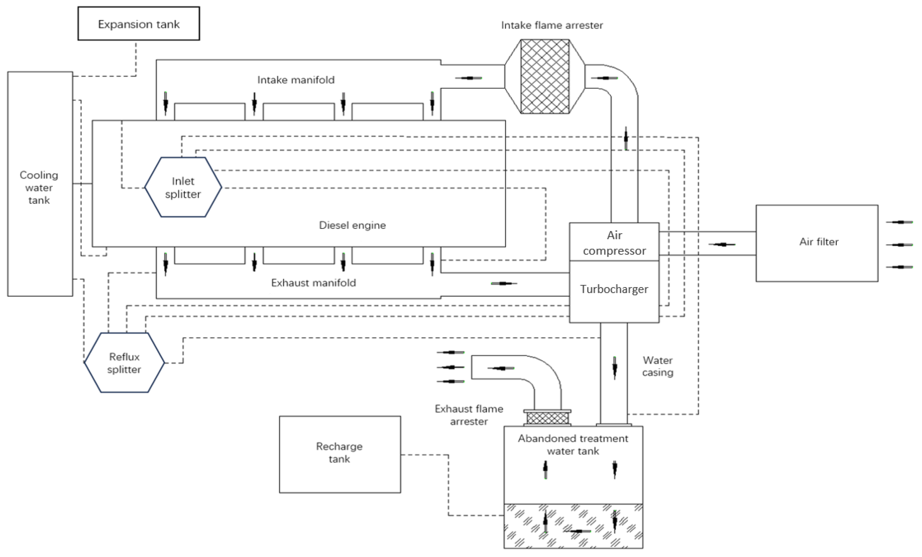
The most widely used exhaust system for explosion-proof diesel engines in the domestic market is the wet exhaust system, as shown in Figure 3. In addition to using exhaust pipes with water jackets and turbochargers, the main characteristic of wet exhaust systems is using cooling and purification water tanks to reduce exhaust temperature. Its advantages are mature technology and simple structure. The main disadvantages are reflected in its large volume and the inconvenient layout of the supporting water tank. During use, a large amount of water is consumed, and it is necessary to add water regularly, resulting in the wastage of water resources. Particles in high-temperature exhaust come into contact with water, cool and condense, and adhere to the exhaust flame arrester, causing significant exhaust back pressure and affecting power and emission performance.

2.4.2. Explosion-Proof Design of Dry Exhaust Gas Cooling System

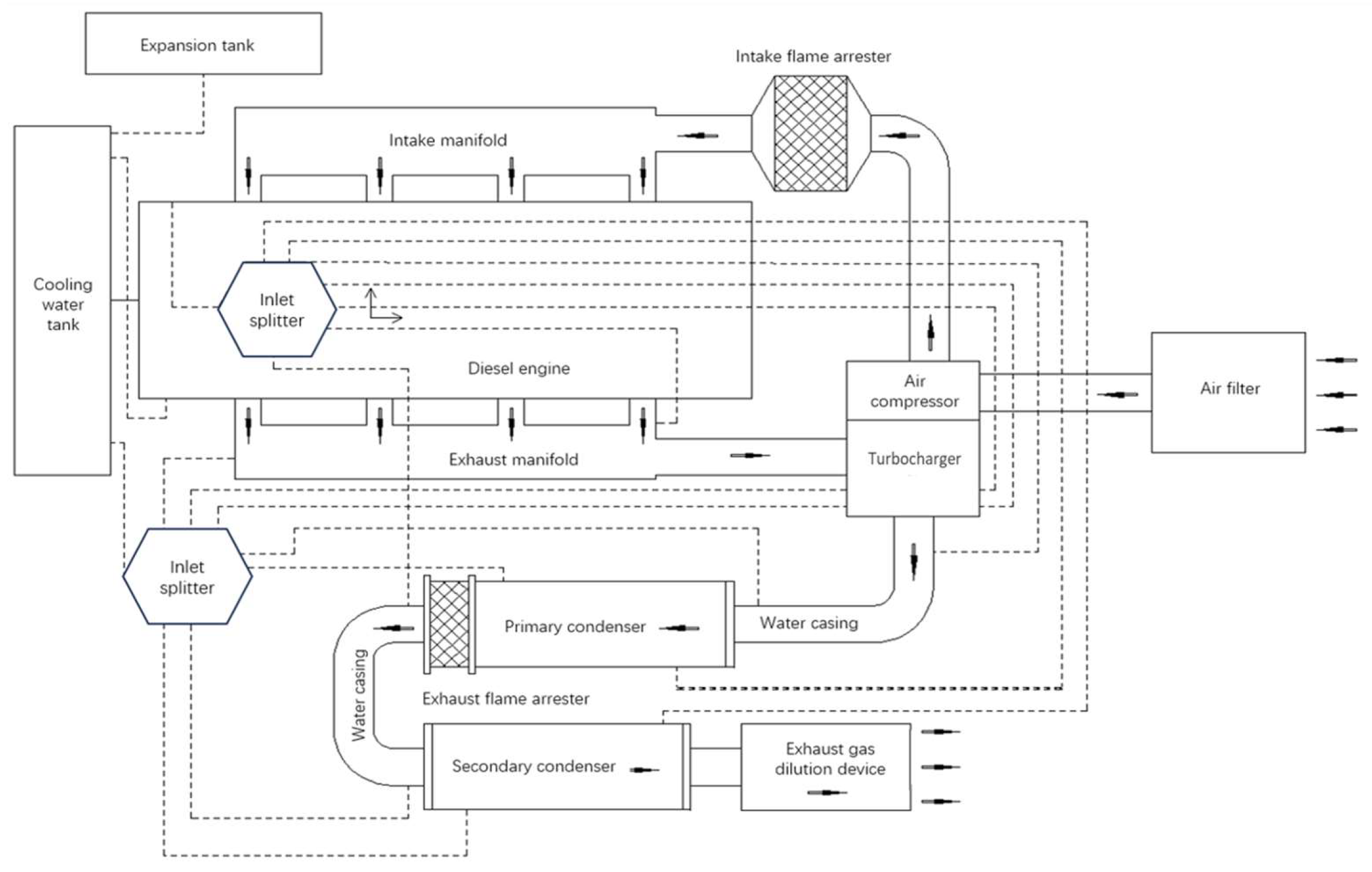
Compared to wet exhaust systems, dry exhaust systems have a lighter and simpler structure, save space, significantly reduce vehicle weight, and do not have the resistance effect of exhaust flame arresters, resulting in better power and emission performance. The main renovation content is to design a two-stage condenser structure and heat exchange component scale based on the exhaust volume and initial exhaust temperature, as well as the dilution amount and size of the exhaust dilution device, to ensure that the exhaust temperature meets regulatory requirements; Design the layout of two-stage condensers and exhaust flame arresters based on exhaust back pressure, real-time power, and emission data to minimize power loss caused by explosion-proof renovations. The dry exhaust system in this experiment mainly consists of a first-stage condenser, a second-stage condenser, exhaust bellows, an exhaust dilution device, and an exhaust flame arrester. As shown in Figure 4.

2.4.3. Explosion-Proof Design of Dry and Wet Exhaust Gas Cooling System

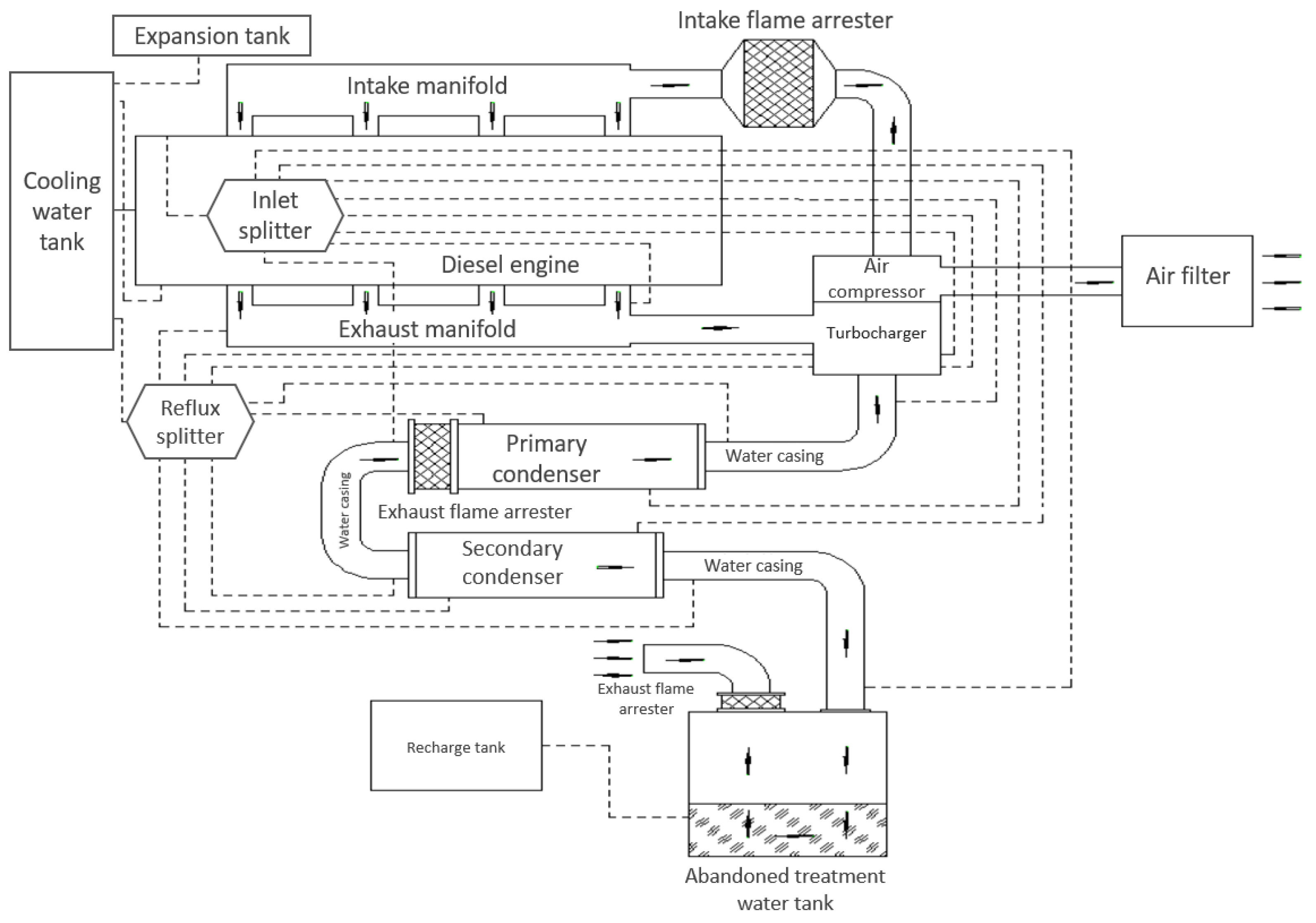
The dry and wet exhaust gas cooling system mainly consists of a dry exhaust gas cooling system added to a cooling purification water tank, as shown in Figure 5. This structure is commonly used in imported diesel engines that meet the EU explosion-proof diesel engine standards. After entering the domestic market, a cooling and purification water tank was added to the original structure to meet the domestic explosion-proof requirements, making its overall structure large and complex.

3. Preparation for the Experiment

3.1. Explosion-Proof Test

3.1.1. Test Equipment

The explosion-proof testing equipment adopts an explosion-proof testing platform built according to the MT990-2006 “General Technical Conditions for Mining Explosion-proof Diesel Engines” standard. This platform can verify the explosion-proof performance of the intake and exhaust systems and the entire machine of the explosion-proof engine. It is divided into an intake and exhaust system explosion-proof test platform (Figure 6A) and a complete machine explosion-proof test platform (Figure 6B). The main technical parameters of the testing equipment are shown in Table 2.

3.1.2. Test Conditions and Working Conditions

Place the three fully assembled explosion-proof exhaust gas cooling systems (without water in the cooling purification box) in a sealed test space. Inject explosive gas containing methane into the interior and ensure that the concentration inside and outside the intake system chamber is uniform, igniting the combustible gas inside the chamber. The methane concentration should be controlled between 7% and 9%, and the oxygen concentration should be controlled between 18% and 21%. The ignition source should be arranged at different positions, such as near the flame arrester, the branch pipe, and the middle of the system. Single or multiple ignition points can be set up depending on the volume and structure. The experiment shall be conducted at least ten times.
The performance testing of the explosion-proof diesel engines with three different exhaust cooling systems began with the installation of the engines on the test bench. Once in place, the engines underwent a preheating phase to ensure they were ready for testing. During this period, the cooling water temperature was carefully monitored, and once it reached 70 °C, the engines were considered sufficiently warmed up to proceed to the next phase.
After the preheating, the engines were operated with no load at a speed of 50% to 60% of their calibrated rated speed. This allowed the engines to stabilize under a low-load condition before moving to more demanding test scenarios. The test area was then sealed off, and a mixture of methane, oxygen, and air was introduced into the enclosed space to simulate the required explosion-proof conditions. The methane concentration was maintained between 7% and 9%, while the oxygen concentration was carefully controlled to remain between 18% and 21%. These conditions were maintained for a 10-min period to ensure the engines operated under the specific environmental parameters.
Once the engines had run for 10 min under these controlled conditions, the throttle and dynamometer were adjusted to increase the engine speed to between 60% and 90% of the rated speed, and the power was set to operate at 50% to 80% of the rated power. The engine was then run at these adjusted parameters for 3 min, simulating typical operational conditions. Following this, the engines were gradually unloaded, and the speed was decreased. The throttle was slowly closed, and the engine was decelerated until it was completely shut down. If needed, the air shutoff valve was also closed to ensure the engine ceased operation fully. The entire testing procedure lasted for a total of 15 min, ensuring that all performance aspects of the explosion-proof diesel engines were thoroughly examined under these controlled and simulated conditions.

3.1.3. Test Equipment

The testing equipment used in this experiment is a non-road national III emission standard detection system based on explosion-proof diesel engines used in coal mines, as shown in Figure 6. The testing system mainly includes an electric dynamometer, torque sensor, throttle controller, data acquisition system, intake air conditioning, fuel consumption meter, particulate matter sampling device, particulate matter weighing bin, explosion-proof test bin, gas analyzer, CVS full flow sampling system and operation console. It can detect the concentrations of NOX, CO, HC and CO2 particulate matter in the exhaust pollutants of mining explosion-proof diesel engines. The main technical parameters of the testing equipment are shown in Table 3.

3.1.4. Test Conditions and Working Conditions

After completing the design of different cooling systems for explosion-proof diesel engines, prototype bench tests were conducted to investigate the impact of varying cooling system designs on the power and economy of explosion-proof diesel engines. To ensure the accuracy of experimental data, the experimental platform conditions are as follows:
The diesel used in the explosion-proof diesel engine experiment is No. 0 diesel, and the engine oil used is 15 W-40 diesel engine oil provided by the source engine manufacturer.
During the experiment, the laboratory intake system adjusted the intake condition of the explosion-proof diesel engine, stabilizing the intake temperature at (25 ± 3) °C and the intake humidity at (50 ± 5)%.
The laboratory air conditioning system adjusted the environmental conditions of the explosion-proof diesel engine during the experiment, maintaining the ambient temperature at (25 ± 5) °C.
The test conditions are mainly based on GB 20891-2014, “Limits and Measurement Methods for Exhaust Pollutants from Diesel Engines for Non-Road Mobile Machinery (China’s Third and Fourth Stages),” and the specific test parameters are shown in Table 4.

4. Experimental Data Analysis

4.1. Explosion-Proof Test

The explosion-proof diesel engine equipped with three different exhaust cooling systems did not experience any explosion during the exhaust system explosion-proof test and the overall explosion-proof test, meeting the standard requirements.

4.2. Performance Test

4.2.1. Exhaust Temperature

Based on the explosion-proof diesel engine’s basic parameters, adjust the engine to operate under different working conditions. After the return water temperature is balanced, measure the exhaust temperature of the explosion-proof diesel engine equipped with three different exhaust cooling systems under different working conditions, as shown in Figure 7.
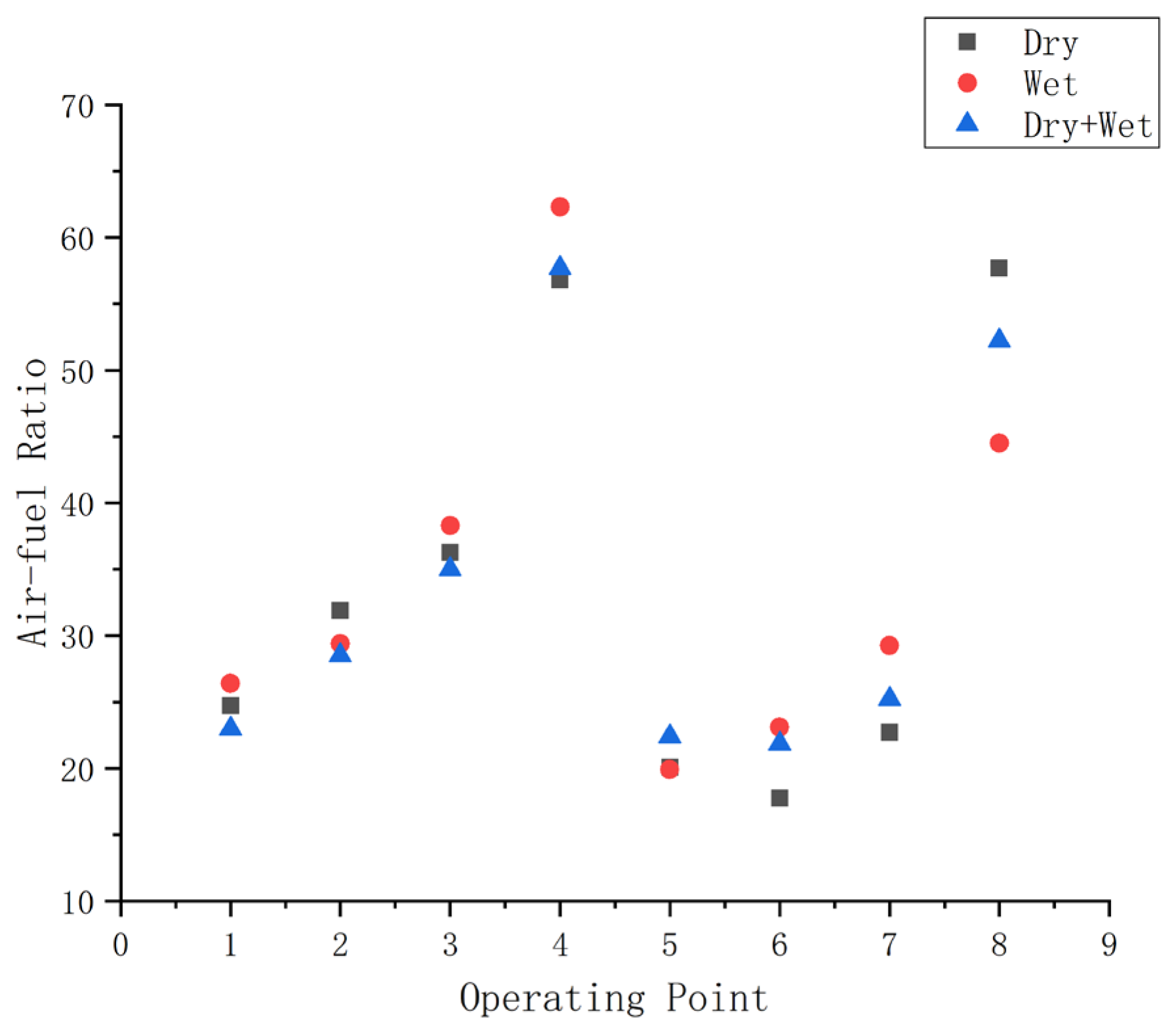
The dry exhaust gas cooling system maintains a higher exhaust temperature at all operating points compared to the other two cooling systems because the exhaust gas does not directly contact water. At the maximum torque point, which corresponds to the fifth operating point, the air-fuel ratio is at its lowest, as shown in Figure 8. This leads to higher combustion chamber temperatures, resulting in an increase in the initial exhaust temperature. As a result, this operating point has the highest exhaust temperature. The exhaust temperature of the dry cooling system, optimized for exhaust temperature, can reach up to 68.5 °C, which is about 4 °C higher than the wet cooling system, but still below the 70 °C threshold, thus meeting the standard requirements.

4.2.2. Surface Temperature

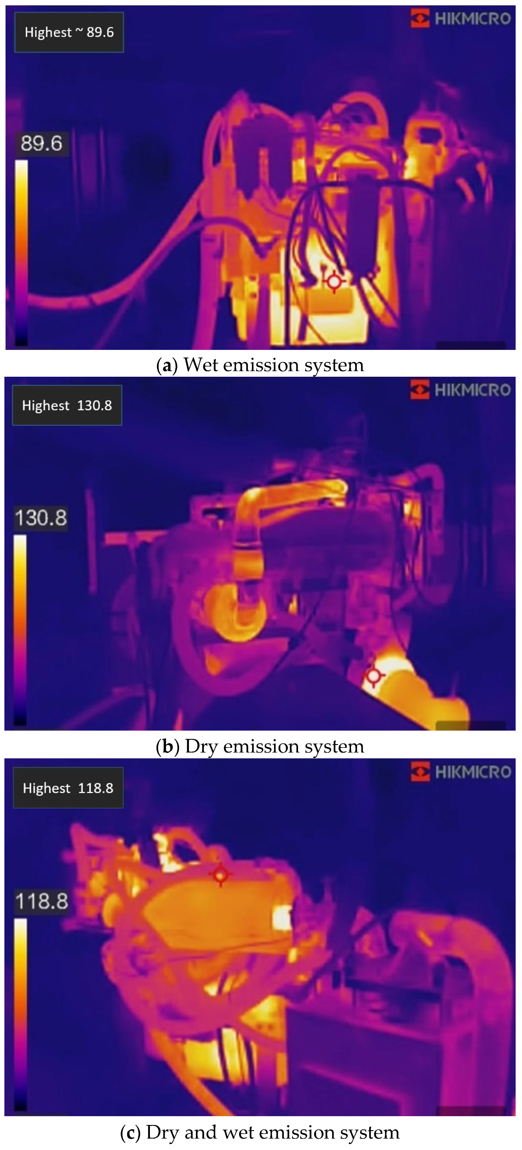
When the cooling water temperature reaches 70 °C, adjust the explosion-proof diesel engine to the rated speed and rated power and run it stably for 1 h. The highest surface temperature of the explosion-proof diesel engine based on three cooling systems is shown in Figure 9:
As shown in the figure above, the dry exhaust cooling system differs from the wet and dry + wet cooling systems because it cannot be cooled by water channels, due to the absence of a cooling purification water tank. Its highest surface temperature occurs at the connection flange of the exhaust dilution device, as shown in Figure 9b, reaching 130.8 °C. In comparison, the wet exhaust cooling system, shown in Figure 9a, has a maximum exhaust temperature about 40 °C higher, but still below 150 °C, which meets the standard requirements. For the dry + wet cooling system in Figure 9c, its highest surface temperature is lower than that of Figure 9a, but higher than that of Figure 9b, due to the presence of water channels. Overall, the highest surface temperature in Figure 9c lies between those in Figure 9a,b, and all three cooling systems comply with the standard requirements.

4.2.3. Power, Torque Performance, and Fuel Consumption

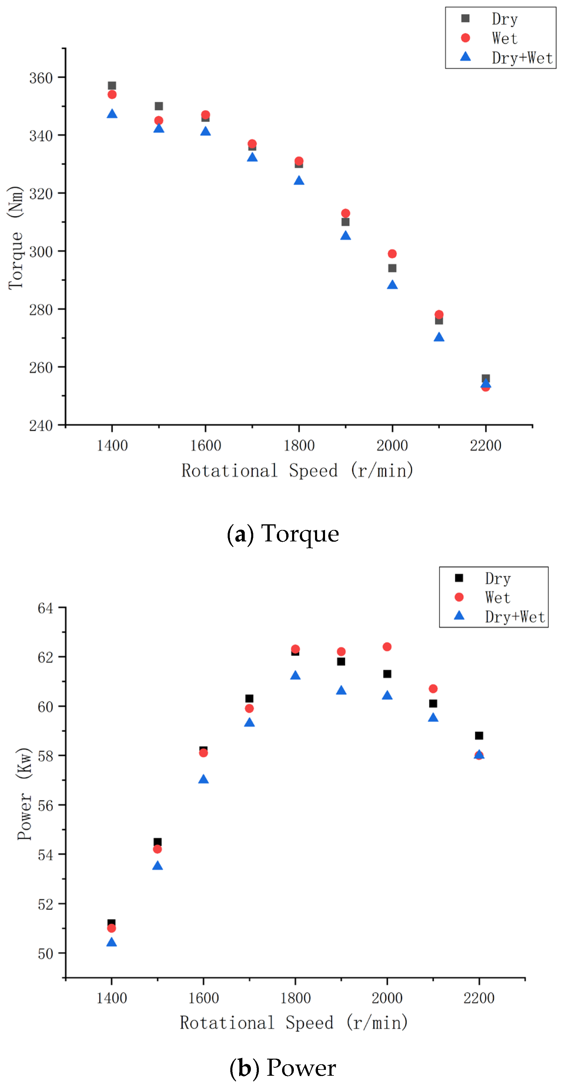
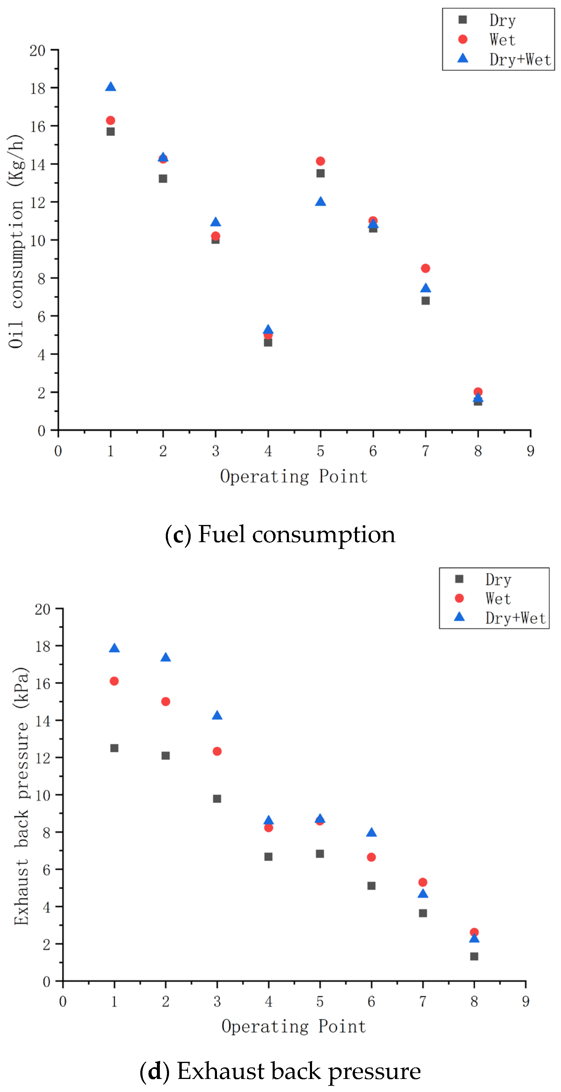
According to the power, torque, fuel consumption, and exhaust back pressure measured under different operating conditions, the three cooling system diesel engine data are shown in Figure 10.
Because the exhaust gas in the dry exhaust cooling system does not pass through a water tank, it avoids direct contact with water. This prevents particles in the exhaust gas from mixing with water and solidifying on the surface of the exhaust flame arrester after cooling. As a result, the dry exhaust cooling system achieves the best exhaust back pressure performance (see Figure 10d), which is 22% lower than that of the wet exhaust cooling system. The exhaust flow is smoother, leading to a 1% increase in the rated power and a 2% increase in the maximum torque compared to the wet exhaust cooling system (see Figure 10a). Fuel consumption is also reduced by 4% (see Figure 10c).
In comparison to the dry + wet exhaust cooling system (see Figure 10b), the dry exhaust cooling system also shows a 1% increase in rated power, a 2% increase in maximum torque (see Figure 10a), and a 13% reduction in fuel consumption (see Figure 10c).

4.2.4. Emission Concentrations

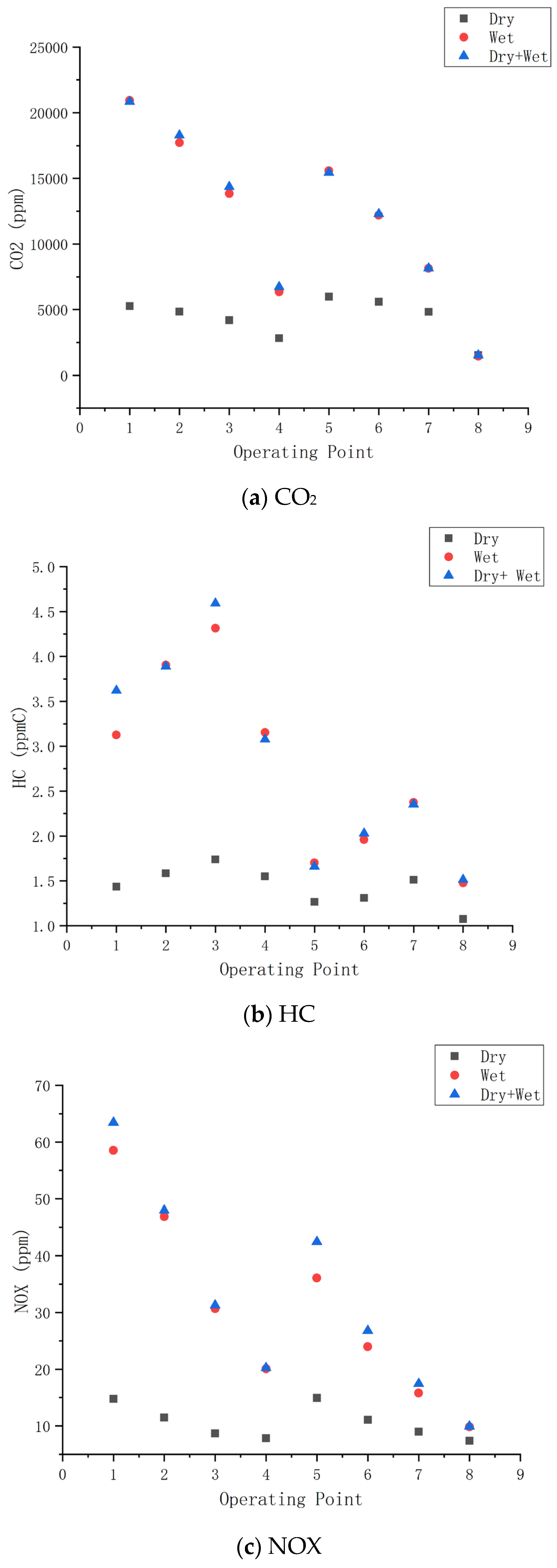
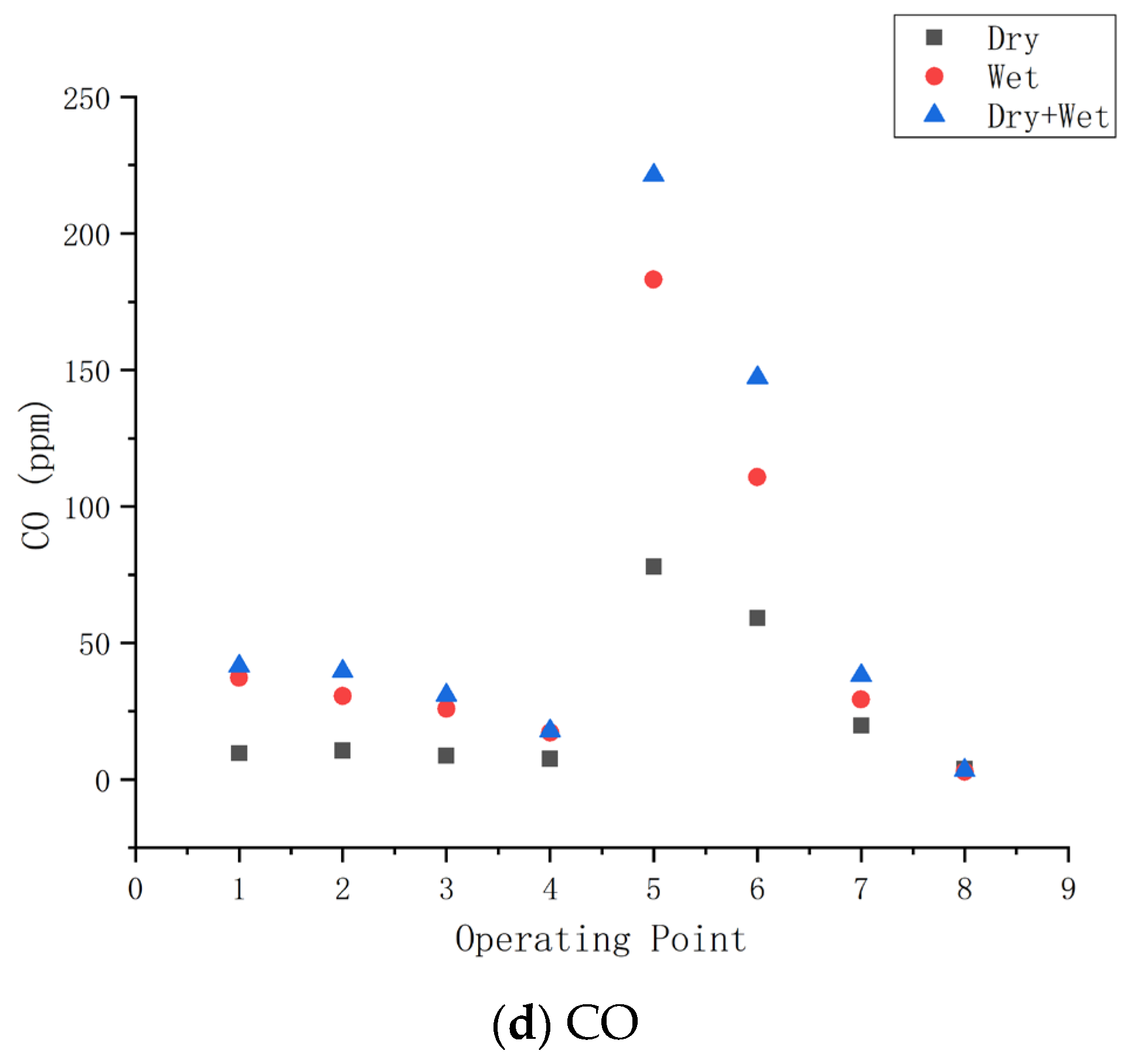
While keeping other structures unchanged, adjust explosion-proof diesel engines equipped with different exhaust cooling systems to achieve the operating parameters shown in Table 4. According to the sampling method specified in GB 20891-2014, “Emission Limits and Measurement Methods for Exhaust Pollutants of Diesel Engines for Non-Road Mobile Machinery (China’s Third and Fourth Stages)”, the emission results shown in Figure 11 are weighted.
As shown in Figure 11a–d, the dry exhaust cooling system significantly outperforms both the wet and dry + wet systems in terms of exhaust emissions. Unlike the wet and dry + wet systems, the dry exhaust cooling system does not require a water tank, preventing exhaust particles from mixing with water and solidifying on the surface of the exhaust flame arrester after cooling. This results in the best exhaust back pressure performance. With lower exhaust back pressure, the system reduces exhaust resistance and improves turbocharger efficiency.
Additionally, the dry exhaust cooling system incorporates an exhaust dilution device that uses exhaust power to generate negative pressure for better dilution. As a result, its emission performance is significantly lower than that of the wet exhaust cooling system: 55% lower in CO, 71% lower in HC, 68% lower in NOX, and 82% lower in CO2. Compared to the dry + wet exhaust cooling system, the dry system shows reductions of 63% in CO, 75% in HC, 66% in NOX, and 94% in CO2.

5. Conclusions

The study demonstrates that the dry exhaust gas cooling system meets the required explosion-proof performance standards while offering several operational advantages over the wet exhaust system.
Explosion-proof Performance: The dry exhaust gas cooling system passed both the exhaust system explosion-proof test and the whole machine explosion-proof test. Although the exhaust and surface temperatures were slightly higher than with the wet system (about 4 °C and 40 °C respectively), it still meets the necessary safety standards.
Fuel Efficiency and Power Performance: The dry exhaust cooling system reduces exhaust back pressure by 22% compared to the wet system, resulting in a 1% increase in rated power and a 2% increase in maximum torque. Additionally, fuel consumption is reduced by 4% compared to the wet system and 13% compared to the combined dry + wet system.
Emissions Reduction: The dry exhaust cooling system significantly reduces emissions, with CO, HC, NOx, and CO2 levels 55%, 71%, 68%, and 82% lower than the wet exhaust system, respectively. Compared to the dry + wet system, the reductions are 63%, 75%, 66%, and 94%, respectively.

6. Future Perspectives

Future improvements could focus on further enhancing the thermal efficiency and emissions reduction of the dry exhaust cooling system, potentially integrating advanced filtration and catalytic technologies. Additionally, optimizing system design for varying operational conditions in coal mines could enhance both performance and safety, meeting stricter environmental regulations in the coming years.

Author Contributions

Conceptualization, Z.S., G.L., C.C., C.M. and M.K.B.; Data curation, H.W., Q.L. and X.Z.; Formal analysis, Y.W.; Investigation, Y.W., Q.L. and C.M.; Methodology, Z.S., H.W., G.L., K.S., C.C. and S.A.M.; Resources, K.S.; Software, C.M.; Supervision, Z.S. and C.M.; Validation, C.M.; Visualization, X.Z. and C.C.; Writing—original draft, G.L. and Q.L.; Writing—review & editing, S.A.M. and M.K.B. All authors have read and agreed to the published version of the manuscript.

Funding

The author(s) disclosed receipt of the following financial support for the research, author-ship, and/or publication of this article: This research is supported by National Natural Science Foundation of China (Grant number: 52274155).

Data Availability Statement

Data are contained within the article.

Conflicts of Interest

Authors Z.S. and C.C. were employed by the company National Mining Product Safety Mark Center Co., Ltd., authors H.W., G.L., Y.W., Q.L., X.Z. and K.S. were employed by the companies Hebei Coal Science Research Institute Co., Ltd. and Hebei Maian Testing Service Co., Ltd. The remaining authors declare that the research was conducted in the absence of any commercial or financial relationships that could be construed as a potential conflict of interest.

References

  1. Ge, S.; Bao, J.; Cao, G. Mining Transportation Technology and Equipment; Coal Industry Press: Beijing, China, 2015. [Google Scholar]
  2. Feng, M.; Han, P.; Li, J. Development and Application of Explosion-proof Diesel Engines in China. Mod. Manuf. Technol. Equip. 2007, 2, 22–23+26. [Google Scholar]
  3. Bao, J.; Liu, Q.; Ge, S.; Yuan, X.; Yin, Y.; Zhang, L. Research Status and Development Trends of Intelligent Technology for Mining Transportation Equipment. Intell. Min. 2020, 1, 78–88. [Google Scholar]
  4. Zhang, R. The Development, Application, and Trends of Explosion-proof Diesel Engines in China. Coal Chem. Ind. 2018, 41, 3. [Google Scholar]
  5. Gao, Z. A Brief Discussion on the Renovation of Explosion-proof Diesel Engines. Electr. Explos. Prot. 2008, 2, 25–26. [Google Scholar]
  6. Cai, Y. Water washing purification method for diesel engine exhaust gas. Explor. Eng. 1985, 3, 57–59. [Google Scholar]
  7. Li, K. Design of Diesel Engine Exhaust Gas Purification Water Tank. Min. Mach. 1983, 5, 1–4. [Google Scholar]
  8. Chu, X.; Li, B.; Chen, L.; Fan, J. Improvement and Testing of Explosion-proof Rubber Wheel Vehicle Exhaust Cooling and Purification Box Structure. Coal Min. Mach. Equip. 2011, 1, 164–166. [Google Scholar]
  9. Zhang, L.; Tang, B.; Bao, J.; Hu, Z.; Peng, Z.; Hu, D.; Yin, Y.; Yuan, X. Design and Performance Test of Four element Combination Exhaust Gas After treatment System for Mining Explosion-proof Diesel Engine. J. Coal Ind. 2024, 49, 2547–2560. [Google Scholar]
  10. Taglialatela, F.; Lavorgna, M.; Iorio, S.D.; Mancaruso, E.; Vaglieco, B.M. Real-time prediction of particle sizing at the exhaust of a diesel engine by using a neural network model. SAE Int. J. Engines 2017, 10, 2202–2208. [Google Scholar] [CrossRef]
  11. Tae, J.W.; Jung, H.K. Simulation study on thermal management strategy to achieve 99% SCR efficiency of a heavy-duty dieselengine over a transient cycle. Int. J. Automot. Technol. 2018, 19, 597–603. [Google Scholar]
  12. Liu, X.; An, S.; Xue, F. Study on the Absorption Efficiency of Exhaust Particulate Matter by Explosion-proof Diesel Engine Exhaust Gas Treatment Box. Coal Min. Mach. 2022. [Google Scholar] [CrossRef]
  13. Zhang, S.; Shen, C. Structural optimization analysis of exhaust gas treatment box for explosion-proof engineering vehicles based on CFD. Mech. Des. Manuf. 2022. [Google Scholar] [CrossRef]
  14. Matsumoto, H.; Ichihara, Y.; Nagasaki, N. Development of the flame-proof diesel vehicle applied new exhaust gas dry type treatment system. J. Min. Mater. Process. Inst. Jpn. 2002, 118, 129–135. [Google Scholar]
  15. Wei, T. Numerical Analysis of Jet Dry Exhaust Pipe for Explosion-proof Diesel Engine. J. Wuhan Univ. Technol. Inf. Manag. Eng. Ed. 2014, 36, 5. [Google Scholar] [CrossRef]
  16. Wang, Y. Optimization measures for exhaust emissions of mining explosion-proof diesel engines. Coal Chem. Ind. 2016, 39, 143–146. [Google Scholar]
  17. McCaffery, C.; Yang, J.C.; Karavalakis, G.; Yoon, S.; Johnson, K.C.; Miller, J.W.; Durbin, T.D. Evaluation of small off-road diesel engine emissions and aftertreatment systems. Energy 2022, 251, 123903. [Google Scholar] [CrossRef]
  18. Han, J.; Kim, T.; Jung, H.; Pyo, S.; Cho, G.; Oh, Y.; Kim, H. Improvement of NOx reduction rate of urea SCR system applied for a non-road diesel engine. Int. J. Automot. Technol. 2019, 20, 1153–1160. [Google Scholar] [CrossRef]
  19. Boccardo, G.; Millo, F.; Piano, A.; Arnone, L.; Manelli, S.; Fagg, S.; Gatti, P.; Herrmann, O.E.; Queck, D.; Weber, J. Experimental investigation on a 3000 bar fuel injection system for an SCR-free non-road diesel engine. Fuel 2019, 243, 342–351. [Google Scholar] [CrossRef]
  20. Ramachander, J.; Gugulothu, S.K.; Sastry, G.R.; Surya, M.S. Statistical and experimental investigation of the influence of fuel injection strategies on CRDI engine as sisted CNG dual fuel diesel engine. Int. J. Hydrogen Energy 2021, 46, 22149–22164. [Google Scholar] [CrossRef]
  21. Jiang, H.; Wang, D.; Cheng, J.; Li, P.; Ji, X.; Shen, Y.; Wu, M. Research on Speed Control Strategies for Explosion-Proof Diesel Engine Monorail Cranes. Actuators 2024, 13, 467. [Google Scholar] [CrossRef]
  22. Di Blasio, G.; Ianniello, R.; Beatrice, C.; Pesce, F.C.; Vassallo, A.; Belgiorno, G. Additive manufacturing new piston design and injection strategies for highly efficient and ultra-low emissions combustion in view of 2030 targets. Fuel 2023, 346, 128270. [Google Scholar] [CrossRef]
Figure 1. Schematic diagram of explosion-proof diesel engine fuel injection.
Energies 18 00610 g001
Figure 2. Explosion-proof diesel engine intake system diagram.
Energies 18 00610 g002
Figure 3. Design diagram of wet exhaust cooling system for explosion-proof diesel engine.
Energies 18 00610 g003
Figure 4. Design diagram of explosion-proof diesel engine dry exhaust cooling system.
Energies 18 00610 g004
Figure 5. Design diagram of explosion-proof diesel engine dry exhaust cooling system.
Energies 18 00610 g005
Figure 6. Non-road country III emission standard detection system.
Energies 18 00610 g006
Figure 7. Exhaust temperature comparison.
Energies 18 00610 g007
Figure 8. Air fuel ratio comparison.
Energies 18 00610 g008
Figure 9. Maximum surface temperature map of explosion-proof diesel engines with different exhaust cooling systems.
Energies 18 00610 g009
Figure 10. Comparison of power and economic performance between different exhaust cooling systems.
Energies 18 00610 g010aEnergies 18 00610 g010b
Figure 11. Exhaust emission diagrams of explosion-proof diesel engines with different exhaust cooling systems.
Energies 18 00610 g011aEnergies 18 00610 g011b
Table 1. Basic parameters of explosion-proof diesel engine.
ProjectParameter
TypeStraight, 4-cylinder, 4-stroke, water-cooled, turbocharged intake
Air intake methodTurbo
Number of cylinders × bore × stroke4 × 105 × 127
Total piston displacement (L)4.4
Compression ratio18.2
Rated speed (r/min)2200
Rated power (kW)62
prototype1104D-E44Tmodel
Electronic fuel injectionKXJ24BOSCH
Table 2. Capability Table of Main Experimental Equipment for Explosion Proof Test.
Serial NumberEquipment NameMain Parameter
1Hydraulic dynamometer0~4000 rpm,
Used for loading explosion-proof diesel engines
2High and low-concentration
methane sensor
Measurement range: 0~10%, Measure methane concentration
3Oxygen sensorMeasurement range: 0~25%, Measure oxygen concentration
4Water ring vacuum pumpPower: 7.5 kW; Gas volume 3.6 m3/min, Extract mixed gas
Table 3. Capacity Table of Main Experimental Equipment for Exhaust Emissions.
Serial NumberEquipment NameMain Parameter
1Siemens electronic dynamometer400 kW, used for loading mining diesel engines
2HBM torque sensor5000 N. m, ±0.5% FS, for torque and speed measurement
3AVL fuel consumption meter±0.15% FS for fuel consumption measurement
4Intake flow meter±1% FS for measuring intake flow rate
5AVL gas analyzer±0.3% FS, testing for concentrations of CO, NOX, HC, etc.
6Particulate matter sampling devicePre-sampling temperature ≤ 52 °C, filter paper 47 mm, for particulate matter entering
7Microgram balanceRow Sampling
8Explosion-proof test chamber±2 ug, measure the mass of particulate matter
9High-flow automatic gas distribution4 m × 8 m × 2 m, providing a sealed environment for explosion-proof testing
Table 4. Performance Experiment Working Condition Parameters Table.
Serial NumberDiesel Engine SpeedLoad Percentage
1Rated speed100
2Rated speed75
3Rated speed50
4Rated speed10
5Intermediate speed100
6Intermediate speed75
7Intermediate speed50
8Idling0
Disclaimer/Publisher’s Note: The statements, opinions and data contained in all publications are solely those of the individual author(s) and contributor(s) and not of MDPI and/or the editor(s). MDPI and/or the editor(s) disclaim responsibility for any injury to people or property resulting from any ideas, methods, instructions or products referred to in the content.