Article

Research on the Decomposition Characteristics of Methane Hydrates Exploited by the NH4Cl/NaNO2 System

1
SanYa Offshore Oil and Gas Research Institute, Northeast Petroleum University, Sanya 572025, China
2
The Key Laboratory of Enhanced Oil and Gas Recovery of Educational Ministry, Northeast Petroleum University, Daqing 163318, China
*
Author to whom correspondence should be addressed.
Energies 2025, 18(5), 1294; https://doi.org/10.3390/en18051294
Submission received: 7 February 2025 / Revised: 1 March 2025 / Accepted: 4 March 2025 / Published: 6 March 2025
(This article belongs to the Section B2: Clean Energy)

Abstract

:
Considering the influence of the system conversion rate on hydrate decomposition kinetics and energy utilization during the decomposition process of pure methane hydrate in the NH4Cl/NaNO2 system (an in situ chemical heat generation system), this study carried out hydrate decomposition experiments in the NH4Cl/NaNO2 system under different decomposition conditions at low temperature and high pressure (3 °C, 8 MPa) and calculated the decomposition efficiency, reaction conversion rate, and methane energy efficiency. The results showed that, based on the differences in the kinetic behavior of hydrate decomposition, the decomposition process was divided into an unstable stage, a stable stage, and a decay stage. When the chemical reaction entered the stable stage, the hydrate decomposition process became stable, and it formed a stable dynamic response mode consisting of an exothermic chemical system and endothermic decomposition of hydrate. Four reactant concentrations (3 mol/L, 4 mol/L, 5 mol/L, and 6 mol/L) and three hydrochloric acid concentrations (0.0178 mol/L, 0.0225 mol/L, and 0.0356 mol/L) were designed. This proved that increases in the reactant concentration and H+ concentration both improved the decomposition efficiency and energy efficiency of pure methane hydrate, but reactant concentrations up to 6 mol/L reduced the decomposition efficiency due to the formation of side reactions, and H+ concentrations up to 0.0356 mol/L produced toxic reddish-brown nitrogen oxides. The overall decomposition efficiency of Cases 1–6 was up to 72.92%, the conversion rate was 25–45%, and the methane energy efficiency was higher than 3.5. The experiment proved the feasibility of exploiting pure methane hydrate in this self-generating heat system, which provides a new idea for the application of this system in hydrate exploitation.

1. Introduction

Methane hydrates are widely distributed around the world in abundant reserves, and they are an efficient and clean energy source. Unlike conventional oil and gas resources, methane hydrate exists in solid form in deep-sea areas and permafrost regions under low temperatures and high pressure [1,2]. Thus, there are great differences between hydrate exploitation and conventional oil and gas reservoir exploitation. Currently, the methane hydrate exploitation methods include the depressurization method [3], thermal stimulation method [4], chemical reagent injection method [5], CH4-CO2 replacement method [6], and combined replacement exploitation method [7,8,9]. The depressurization method has the advantages of simple operation and low cost; its limitation is that it cannot transfer heat in the hydrate decomposition process [10]. The thermal stimulation method can control the decomposition process of hydrates and adjust the gas production rate by injecting heat, yet it has a large heat loss and a relatively low exploitation efficiency [11]. The chemical reagent injection method is currently applied less often in hydrate exploitation and is mainly used to prevent hydrates from clogging natural gas transportation pipelines [12]. The CO2 replacement injection process is difficult to carry out and time-consuming, and it has a low methane recovery rate, making it difficult to achieve the commercial application of methane hydrate. The recovery rate of the combined replacement exploitation method is higher than that of the single replacement method, but the energy consumption and benefits of heat injection also need to be considered [10]. In recent years, a method of exploiting hydrates using a self-heating system was proposed by some scholars. Compared with other exploitation methods, the self-heating exploitation method has the advantages of simple construction, low cost, and a relatively good exploitation effect, and the heat loss phenomenon during the injection process is not obvious. The most common chemical heat generation systems are the following: the NH4Cl/NaNO2 system, the CO (NH2)2/NaNO2 system, the CrO3/C6H12O6 system, and the H2O2 system. Considering the safety, economy, heat production, and recovery rate of self-heating systems, the NH4Cl/NaNO2 system is most commonly used to exploit methane hydrate [13].
In 2020, Wang Yefei et al. studied the reaction characteristics of the NH4Cl/NaNO2 system, clarified the influences of the reactant concentration ratio, H+ concentration, and initial reaction temperature on the system reaction, and obtained the reaction kinetic equation of the system under acidic conditions [14]. In 2023, Zhan Yongping et al. studied the critical H+ concentration and conversion rate of the reaction of NH4Cl/NaNO2 to generate N2 under acidic conditions and established a reaction kinetic equation considering the conversion rate. However, the characteristics of the kinetic behavior and system energy utilization of the methane hydrate decomposition process in the NH4Cl/NaNO2 system under different decomposition conditions have not been studied in depth [15]. Therefore, this study designed experiments on the decomposition of methane hydrate by the self-heating system under different decomposition conditions based on the reaction kinetic equation of the self-heating system while considering the conversion rate in combination with the experimental results. The characteristics of hydrate decomposition and energy efficiency were analyzed under different experimental conditions. This study can be used as a research basis for further analysis of the kinetic behavior of methane hydrate decomposition by self-heating systems.

2. Materials and Methods

2.1. Materials

CH4 (purity of 99%), N2 (purity of 99%), H2O (deionized water), NaNO2 (analytical purity, Tianjin Damao, Tianjin, China), NH4Cl (analytical purity, Tianjin Damao), and HCl (14%, Quanrui Reagent, Jinzhou, China) were used.

2.2. Methods

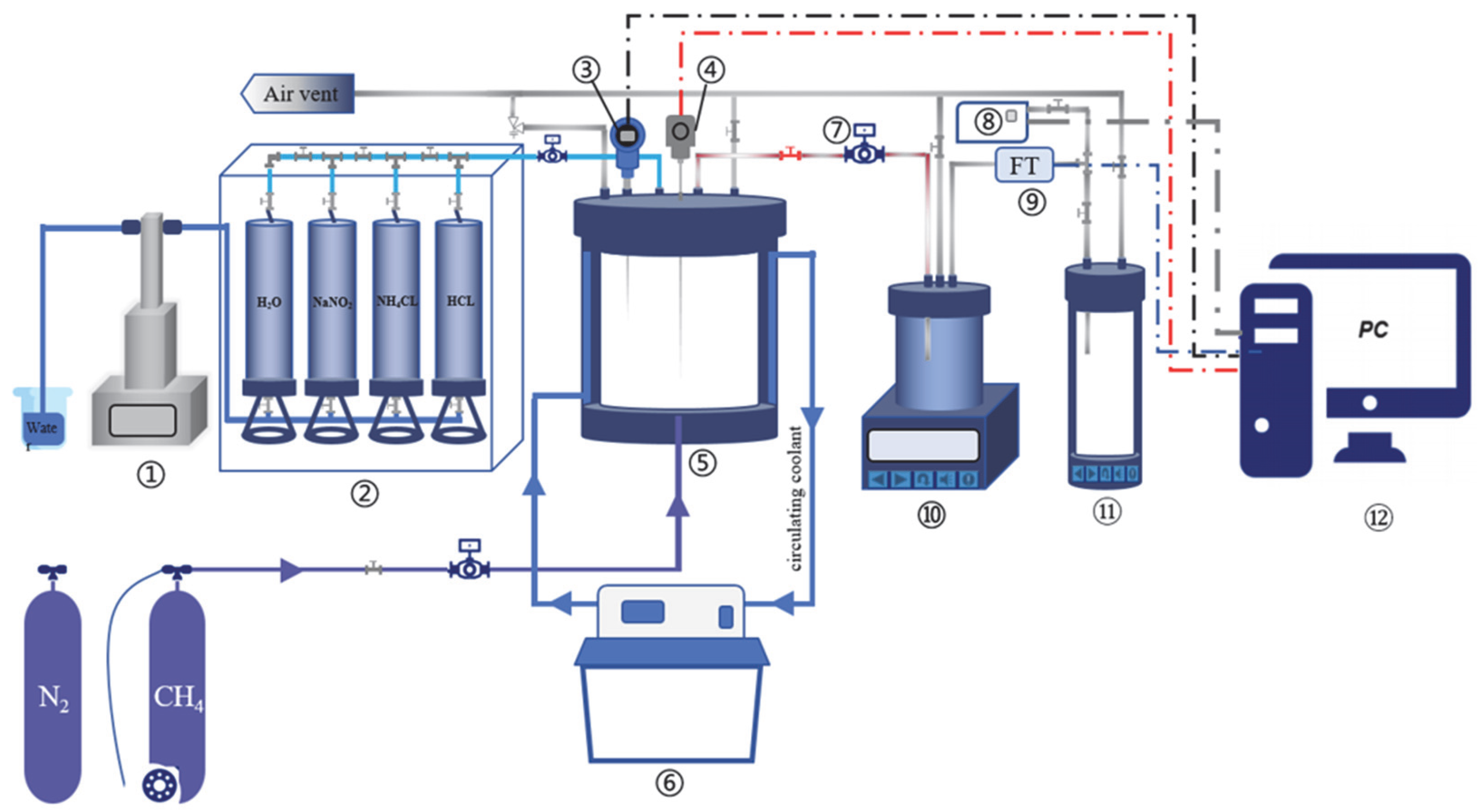
2.2.1. Experimental Apparatus

Figure 1 depicts the experimental system for methane hydrate generation and decomposition, which consists of five parts. The autoclave reaction system (25 ± 0.05 MPa, −25–100 °C, 0.86 L) is made of Hastelloy. The multiphase fluid injection system uses a PID pressure controller (≤20 ± 0.05 MPa, TY901) to keep the gas injection and liquid injection pressures constant with a constant-speed double-cylinder pump (ISCO 1000D, Teledyne Isco, Thousand Oaks, CA, USA). The low-temperature circulating cooling system consists of a cooling circulator (HWY-30, Hebei Zhongxin, Hebei, China, high- and low-temperature water baths) and a cooling jacket to ensure that the temperature of the autoclave remains constant at a low temperature; the multiphase fluid separation and gas collection system consists of a gas–liquid separator (JT-LV, Hangzhou JT, Hangzhou, China, 2.2 L, ±2%~±3%), a gas collection device (with pressure and temperature detection functions, 3.8 L), and a gas chromatograph, and it uses a PID pressure controller to control the outlet pressure at the preset pressure for the experiment. The data acquisition system collects and aggregates the data obtained by a pressure transducer (±0.5%FS), temperature transducer (±0.2 °C), gas chromatograph (<2%), and gas flowmeter (±0.25%).

2.2.2. Experimental Operation Process

This research included experiments on the decomposition of hydrates by the self-heating system under different decomposition conditions (Cases 1–6). The decomposition experiments in different cases involved an experimental group and a parallel sample group. The specific experimental cases are shown in Table 1. The pressure and temperature of the decomposition experiments in this study were chosen with reference to the experimental results on the pure methane hydrate phase equilibrium obtained by Geng et al. [16] through tests on the methane hydrate reservoir conditions in the South China Sea. Taking Case 1 as an example, the experimental steps of the hydrate synthesis and decomposition processes can be described as follows.
  • Methane hydrate synthesis process.
The airtightness of the apparatus was checked, and a hydrate generation experiment was conducted by using the excess methane gas method. Firstly, the circulating cold water of the low-temperature circulating cooling system was set to 3 °C, and the pressure in the apparatus was kept at 10 MPa. At this time, the hydrate began to form. When the pressure and temperature remained unchanged within 12 h, this indicated that the synthesis of methane hydrate was complete, and the quality of deionized water was recorded as m H 2 O .
  • The process of hydrate decomposition by the self-heating system.
  • Deionized water was used to prepare a NH4Cl solution (3 mol/L, 200 mL), NaNO2 solution (3 mol/L, 200 mL), and HCl solution (0.0225 mol/L, 10 mL). They were placed in the intermediate containers of the high-pressure pistons and kept at a constant temperature of 3 °C for 12 h of standby.
  • The outlet valve was opened, and the PID pressure controller was used to reduce the initial pressure after the completion of hydrate formation to 8 MPa and stabilize it for 1 h.
  • The injection pump was opened, and 100 mL of NH4Cl solution and 100 mL of NaNO2 solution were injected into the reactor in sequence at an injection rate of 30 mL/min, and then, 1.17 mL of HCl solution was injected at an injection rate of 0.1 mL/min. The back pressure at the outlet was controlled to 8 MPa, and excess methane gas was discharged until the pressure stabilized. This was recorded as the zero point of the reaction time, and the injection valve was closed.
  • The multiphase fluid separation and gas collection system was opened; the volume of the excessive methane gas discharged in steps b) and c) was recorded; and the changes in experimental data, such as pressure, temperature, and gas production volume, during the decomposition process were recorded at an interval of 1 min. The gas chromatograph was used to sample and analyze the gas components and volume fractions in the collector every 30 min (about 1 × 10⁻⁵ m3 of gas was collected each time).
  • When the gas flowmeter detected that the gas production was 0 or the sampling analysis results of the gas chromatograph did not contain or contained a very small amount of methane gas, the decomposition experiment was completed.
  • After the end of the decomposition experiment, the number of moles of methane gas collected by the gas chromatograph and the number of moles of methane gas in the collection device were recorded and calculated, and the total number of moles of methane gas produced was calculated.

2.2.3. Calculation Method

  • Instantaneous decomposition efficiency and overall decomposition efficiency.
The self-heating system is represented by Equation (1).
NH4Cl + NaNO2 = NaCl + N2 + 2H2
During the process of hydrate decomposition by the self-heating system, the instantaneous decomposition efficiency and the overall decomposition efficiency of methane are used to comprehensively evaluate the influence of the heat release and gas production of the chemical reactions in the self-heating system on the decomposition effect of hydrates. The instantaneous decomposition efficiency η C H 4 , t and the overall decomposition efficiency η C H 4 , t f are calculated using Equations (2) and (3), respectively.
η C H 4 , t = n t n t 1 n init × 100 %
η C H 4 , t f = n t f n 0 n init × 100 %
n t ,   n t 1 is calculated using Equation (4).
n t = X C H 4 , t P t V g Z R T t
t = 0, n t is calculated using Equation (5).
n 0 = P 0 V D Z R T 0
n init is calculated using Equation (6).
n init = m H 2 O N M H 2 O
  • Energy efficiency.
The energy efficiency λ is another important indicator for evaluating the decomposition effect of hydrates. It refers to the ratio between the heat Q C H 4 , m generated by the combustion of methane gas produced in the decomposition of methane hydrate and the total heat input into the system. The total heat input into the system is divided into two processes, namely, the heat release Q l of the chemical reactions of the NH₄Cl/NaNO2 system considering the conversion rate and the change value of heat release Q N 2 , c during the process of N2 replacing methane hydrate. However, according to the test results of Lee et al. [17], who used a high-pressure differential scanning calorimeter, there was no obvious heat change or obvious structural transformation and hydrate dissociation during the replacement of pure methane hydrate with flue gas (CO2 + N2), that is, Q N 2 , c 0 . Therefore, the energy efficiency λ can be calculated using Equation (7).
λ = Q C H 4 , m Q N 2 , c + Q l + Q C H 4 = n p Δ H m χ n l Δ H + n p Δ H n
Here, the conversion rate χ can be represented by Equation (8) for the reaction kinetic equation of the NH₄Cl and NaNO2 systems considering the reaction conversion rate [15].
( 1 χ ) 1.346 1 1.346 = 4.74 × 10 4 e 3389 / T i c ( H + ) 1.545 c 0 1.346 t

3. Results

3.1. The Decomposition Characteristics of Hydrate Under Different Decomposition Conditions

According to the changes in temperature and pressure in the reactor with time in Cases 1–6, the decomposition process was divided into three decomposition stages: the unstable stage, the stable stage, and the decay stage (regular changes are shown in Figure 2).
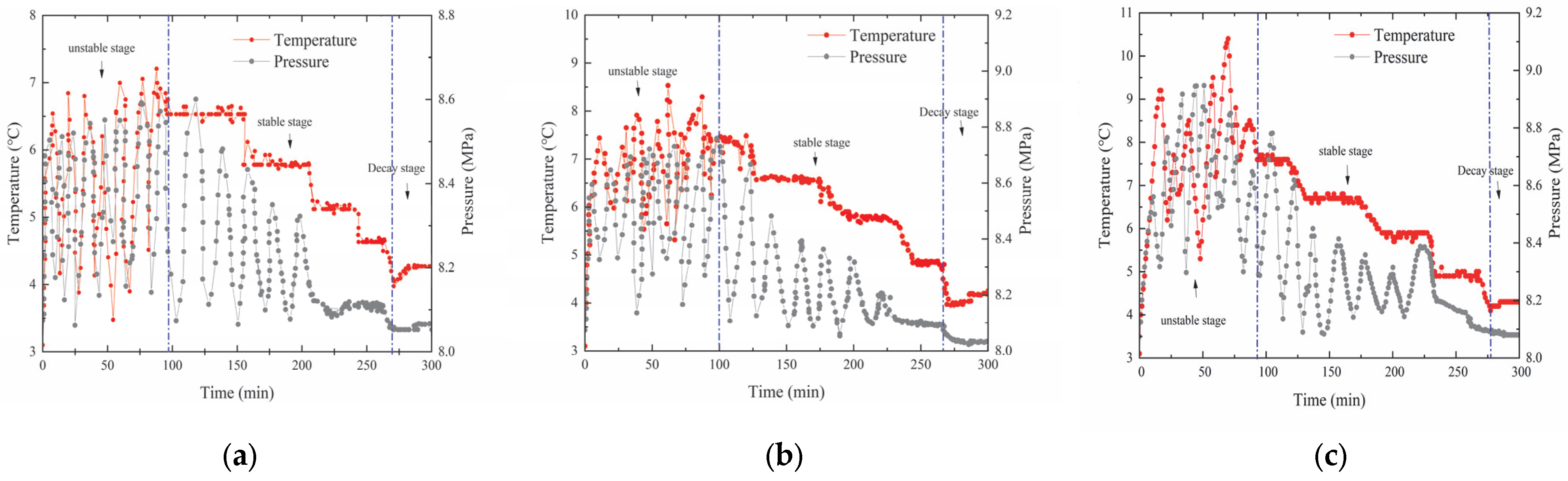
  • Unstable stage: in the early stage of decomposition, the temperature and pressure in the reactor changed drastically. Analysis of the reasons: The external temperature of the reactor was stable due to the influence of the circulating cooling device, while the experimental temperature in the reactor was unstable, which was quite different from the temperature change in the conventional hot water injection process [18]. The reason is that during the decomposition of hydrates by the self-heating system, a large amount of heat was released when the two substances first came into contact with each other (relevant studies have shown that the heat released during the initial reaction process between the two substances can result in a sharp rise in the ambient temperature [14]). The self-protection effect of the hydrates’ “quasi-liquid film” inhibited the diffusion and mass transfer of methane hydrate. Above the freezing point, the higher the temperature, the thinner the quasi-liquid film thickness, the lower the mass transfer resistance, and the faster the methane diffusion rate, which made the hydrate decomposition rate faster. Compared with the constant-temperature steady-state process of hot water injection, the temperature change in the chemical reaction was a dynamic process and was more drastic. The whole system was in an unsteady state, and the system temperature affected the intensity of the chemical reaction. Therefore, the thickness of the hydrates’ quasi-liquid film was changed accordingly, and it ultimately showed the instability of the decomposition rate, the system temperature, and the pressure.
  • Stable stage: This stage was the main decomposition stage of methane hydrate. At this time, the gas production and heat generation of the chemical reaction system made the solid methane hydrate decompose gradually. With the decrease in the chemical reaction rate and the hydrate content, the decomposition pressure and decomposition temperature also gradually decreased. It was observed that the temperature changed in steps over time in the reaction process. This phenomenon proves that as the chemical reaction enters a stable state, the hydrate decomposition process gradually becomes stable, thus forming a dynamic change law involving an exothermic chemical system and endothermic decomposition of the self-heating system. At the later stage of decomposition, the decrease in the chemical reaction rate reduced the heat production, and the temperature in local areas decreased accordingly. The overall temperature in the reactor dropped earlier than the phase equilibrium temperature of methane hydrate, resulting in a reduction in the stable decomposition time of hydrates.
  • Decay stage: During this stage, the pressure and the temperature were higher than the back pressure value, and a small ’funnel’ rise in temperature reflected that the chemical reaction system in the self-heating system still maintained a relatively low reaction rate. At this time, the reaction conditions had decreased until they were almost unable to continue to break through the phase equilibrium of methane hydrate, so the stable generation of N2 during this stage made no significant changes in the pressure and temperature in the system, which marked the end of the decomposition experiment.

3.2. Effects of Different Decomposition Conditions on Decomposition Efficiency

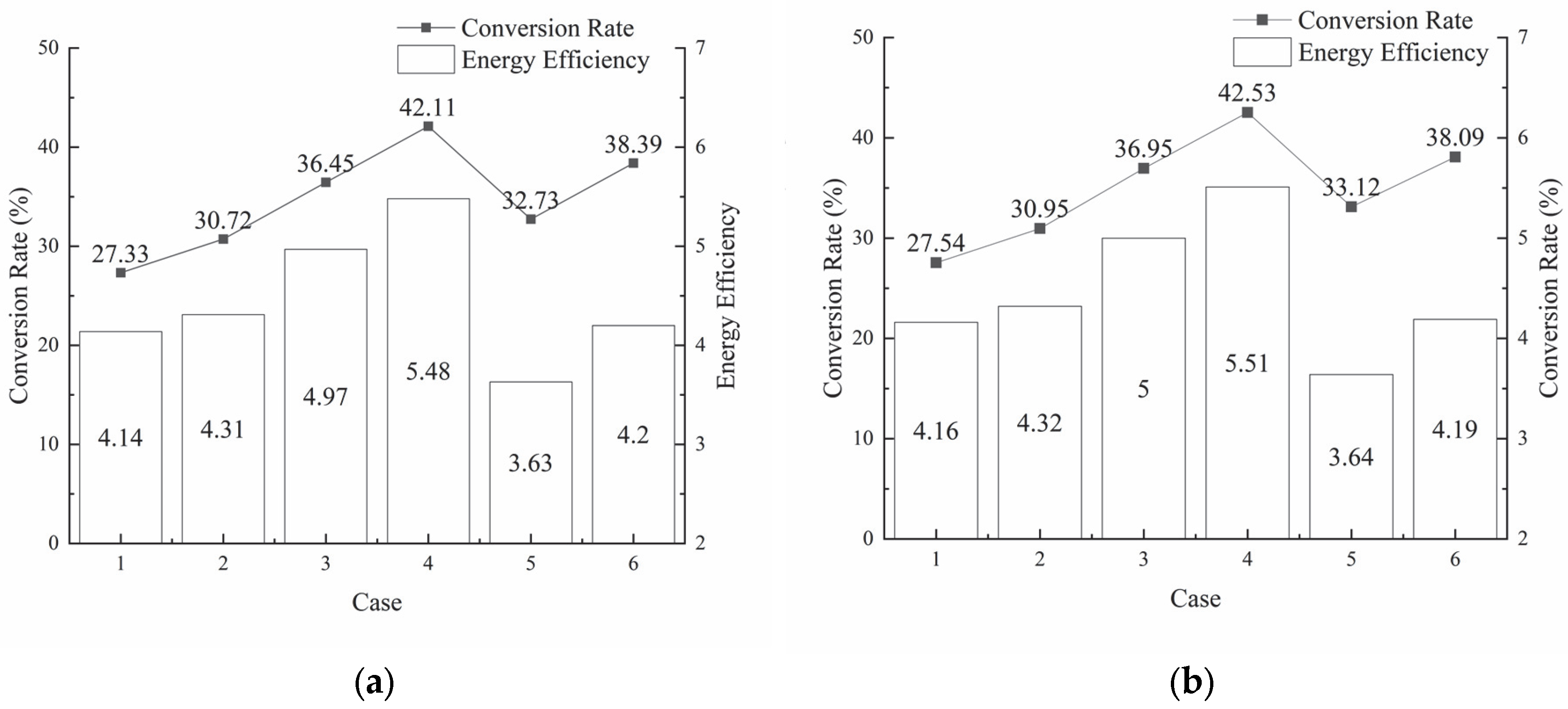
3.2.1. Effects of Reactant Concentration on Decomposition Efficiency

Comparing the curves of the relationship between the instantaneous decomposition efficiency and time in Figure 3a, it was found that the instantaneous decomposition efficiency followed the order of Case 4 > Case 3 > Case 2 > Case 1. When the reactant concentration increased from 3 mol/L to 5 mol/L, the peak value of the average instantaneous decomposition efficiency increased from 10.81% to 12.38%, and the peak time of instantaneous decomposition efficiency was also different; the higher the concentration, the faster the peak appeared. When the reactant concentration was 6 mol/L, the peak time of instantaneous decomposition efficiency appeared later than that when the reactant concentration was <6 mol/L. This was because, in the same amount of solution, a higher concentration of the reactant resulted in more solutes of the reactants being able to participate in the decomposition reaction; the more fully the reaction could be achieved, the faster the decomposition speed and the higher the decomposition efficiency. When the reactant concentration was 6 mol/L, the decomposition efficiency decreased, and the peak appeared 100 min later. This could have been due to side reactions occurring under high-concentration conditions, leading to a slower decomposition speed. It can be seen in Figure 3b that the overall decomposition efficiency increased with the increase in reactant concentration. Therefore, this could be considered to appropriately increase the reactant concentration to improve the decomposition efficiency of methane hydrate.

3.2.2. Effects of H+ Concentration on Decomposition Efficiency

In Figure 3a, it can be observed that the instantaneous decomposition rate followed the order of Case 6 > Case 3 > Case 4. When the H+ concentration increased from 0.0178 mol/L to 0.0356 mol/L, the instantaneous decomposition efficiency generally increased, and the peak value of the average instantaneous decomposition rate increased from 11.45% to 13.99%. The higher the H+ concentration, the faster the peak value of the instantaneous decomposition efficiency appeared. This was due to the dynamic reaction between H+ and NO2⁻ to accelerate the decomposition of hydrates. Zhan Yongping et al. [15] found that the increase in H+ concentration had a relatively large impact on the reaction decomposition efficiency but had little impact on the final gas production results. It can be seen in Figure 3b that the overall decomposition efficiency increased with the increase in H+ concentration, which further proved that the more H+ in the system, the higher the decomposition efficiency of methane hydrate. However, when the H+ concentration reached 0.0356 mol/L, the maximum reaction temperature reached 13.1 °C, and a reddish-brown gas was generated during the reaction process. This could have been due to the reaction being incomplete and HNO2 decomposing to produce nitrogen oxides (HNO2). Therefore, moderately increasing the H+ concentration could accelerate the hydrate decomposition process, but in order to avoid the generation of toxic gases, the H+ concentration should be controlled below 0.0356 mol/L.

3.3. Analysis of Energy Efficiency Under Different Decomposition Conditions

It can be observed in Figure 4 that the reaction conversion rates of both the experimental group and the parallel sample group in Cases 1–6 were 25–45%, and the methane energy efficiencies were above 3.5. Comparing the changes in the reaction conversion rates and methane energy efficiencies in Cases 2, 3, 5, and 6, it was found that when the acid concentration was kept constant and the reactant concentration was increased, the conversion rate and methane energy efficiency increased significantly. Comparing the changes in the reaction conversion rates and methane energy efficiencies in Cases 1, 2, and 4, it was found that, when the reactant concentration was kept constant and the acid concentration was increased, both the reaction conversion rate and the methane energy efficiency tended to increase, but the amplitude of this increase was not obvious. Wu Anming and Nguyen et al. [19,20] found that when the H+ concentration in the system was constant, the reaction order and the reaction activation energy of the NH4Cl/NaNO2 system remained basically unchanged. This further proved that H+ has a catalytic effect, and it mainly affects the reaction decomposition efficiency but has little impact on the conversion rate.

4. Conclusions

Using the changing relationship between the chemical reaction rate and the decomposition conditions, the decomposition process was divided into an unstable stage, a stable stage, and a decay stage. The self-protection effect of hydrates inhibited the molecular diffusion of methane hydrate, and the intense chemical reactions in the unstable stage were one of the main reasons for the unstable stage. When the chemical reaction entered the stable stage, the hydrate decomposition process became stable, forming a stable dynamic response mode of heat release by the chemical system and heat absorption decomposition of hydrates (i.e., it formed a stable dynamic change mode involving an exothermic chemical system and endothermic decomposition of the self-heating system).
The reaction processes of the NH4Cl/NaNO2 system were analyzed under different decomposition conditions. The reactant concentration and H+ concentration had a great impact on the reaction decomposition efficiency. When the experimental decomposition temperature was 3 °C and the decomposition pressure was 8 MPa, the reaction decomposition efficiency was the highest when the reactant concentration was 6 mol/L and the H+ concentration was 0.02256 mol/L.
The H+ concentration accelerated the reaction decomposition efficiency of the NH4Cl/NaNO2 system but had little impact on the conversion rate. This was because H+ mainly played a catalytic role in the reaction, while the reactant concentration was the main factor affecting the reaction conversion rate. Therefore, in order to improve the conversion rate and energy efficiency of the chemical system, it is possible to increase the reactant concentration to improve the decomposition efficiency. However, too high of a reactant concentration would produce side reactions that slow down the decomposition efficiency.

Author Contributions

Conceptualization, J.Z.; methodology, Y.W. (Yi Wan); software (Origin 2021), M.L.; validation, Y.W. (Yi Wan); formal analysis, M.L.; investigation, Y.W. (Yanan Wang); resources, J.Z.; data curation, X.T.; writing—original draft preparation, Y.W. (Yi Wan); writing—review and editing, J.Z.; visualization, X.T.; supervision, J.Z.; project administration, Y.W. (Yanan Wang); funding acquisition, J.Z. All authors have read and agreed to the published version of the manuscript.

Funding

This work was supported by the Hainan Province Key Research and Development Program Project (ZDYF2022GXJS013).

Data Availability Statement

The original contributions presented in this study are included in the article; further inquiries can be directed to the corresponding author.

Conflicts of Interest

The authors declare that this research was conducted in the absence of any commercial or financial relationships that could be construed as potential conflicts of interest.

Abbreviations

Symbol Explanation
c 0 initial concentration of reactants in the reaction system, mol/L
c (H+)concentration of H+ in the reaction system, mol/L
Δ H m enthalpy of combustion of methane gas, 8.896 × 10 5 J/mol
Δ H n decomposition heat of methane gas, 5.6 × 10 4 J/mol
Δ H enthalpy of the NH4Cl and NaNO2 system, 3.3258 × 10 5 J/mol
m H 2 O mass of deionized water consumed during hydrate synthesis, g
M H 2 O molar mass of water, g/mol
n init - initnumber of moles of methane initially contained in the solid hydrate after hydrate synthesis, mol
n 0 the mole number of excess methane gas after hydrate synthesis at the reaction zero point, mol
n t 1 , n t the mole number of methane gas in the mixed gas in the collector at time t − 1 and time t, respectively, mol
n t f the number of moles of methane in the mixed gas in the collector at the end of decomposition ( t f ) , mol
n p total number of moles of methane gas produced during the decomposition of methane hydrate, mol
n l number of moles of the NH4Cl/NaNO2 system, mol
N hydration index; methane hydrate is taken as 6.12 [21]
P 0 , P t reaction zero point, gas mixture pressure at moment t, Pa
Q C H 4 , m heat generated by the combustion of methane gas, J
Q C H 4 heat generated by the decomposition of methane gas, J
Q l total heat produced in the reaction of the NH4Cl/NaNO2 system, J
Q N 2 , c value of heat change during the replacement of hydrate by nitrogen, J
R ideal gas constant, taking 8.314 J/(mol · K)
T 0 , T t temperature of the gas in the collector at the zero point of the reaction and at the moment of t, K
T i decomposition temperature in the reactor at the end of decomposition, K
V D volume of excess methane gas discharged from the reactor at the end of hydrate synthesis at the zero point of the reaction, m3
V g volume occupied by the gas mixture in the collector, m3
Z methane gas compression factor (calculated from the Pitzer correlation equation)
X CH 4 , t Molar fraction of methane in the mixed gas in the collector at time t (measured by gas chromatography), %
η CH 4 , t , η CH 4 , t f instantaneous decomposition efficiency and overall decomposition efficiency of methane hydrate, respectively, %
λ energy efficiency in the process of decomposition of methane hydrate by an autogenous thermal system
χ conversion rate of the reaction system, %

References

  1. Boswell, R.; Collett, T.S. Current perspectives on gas hydrate resources. Energy Environ. Sci. 2011, 4, 1206–1215. [Google Scholar] [CrossRef]
  2. Pinero, E.; Marquardt, M.; Hensen, C.; Haeckel, M.; Wallmann, K. Estimation of the global inventory of methane hydrates in marine sediments using transfer functions. Biogeosciences 2013, 10, 959–975. [Google Scholar] [CrossRef]
  3. Zhao, J.; Liu, Y.; Guo, X.; Wei, R.; Yu, T.; Xu, L.; Sun, L.; Yang, L. Gas production behavior from hydrate-bearing fine natural sediments through optimized step-wise depressurization. Appl. Energy 2020, 260, 114275. [Google Scholar] [CrossRef]
  4. Li, B.; Liu, S.D.; Liang, Y.P.; Liu, H. The use of electrical heating for the enhancement of gas recovery from methane hydrate in porous media. Appl. Energy 2018, 227, 694–702. [Google Scholar] [CrossRef]
  5. Tupsakhare, S.S.; Kattekola, S.; Castaldi, M.J. An Application of the Results from the Large Scale Thermal Stimulation Method of Methane Hydrate Dissociation to the Field Tests. Ind. Eng. Chem. Res. 2017, 56, 4588–4599. [Google Scholar] [CrossRef]
  6. Boswell, R.; Schoderbek, D.; Collett, T.S.; Ohtsuki, S.; White, M.; Anderson, B.J. The Inik Sikumi Field Experiment, Alaska North Slope: Design, Operations, and Implications for CO2-CH4 Exchange in Gas Hydrate Reservoirs. Energy Fuels 2017, 31, 140–153. [Google Scholar] [CrossRef]
  7. Shi, M.; Woodley, J.M.; von Solms, N. An Experimental Study on Improved Production Performance by Depressurization Combined with CO2-Enriched Air Injection. Energy Fuels 2020, 34, 7329–7339. [Google Scholar] [CrossRef]
  8. Khlebnikov, V.N.; Antonov, S.V.; Mishin, A.S.; Bakulin, D.A.; Khamidullina, I.V.; Liang, M.; Vinokurov, V.A.; Gushchin, P.A. A new method for the replacement of CH4 with CO2 in natural gas hydrate production. Nat. Gas Ind. B 2016, 3, 445–451. [Google Scholar] [CrossRef]
  9. Zhang, L.X.; Yang, L.; Wang, J.Q.; Zhao, J.; Dong, H.; Yang, M.; Liu, Y.; Song, Y. Enhanced CH4 recovery and CO2 storage via thermal stimulation in the CH4/CO2 replacement of methane hydrate. Chem. Eng. J. 2017, 308, 40–49. [Google Scholar] [CrossRef]
  10. Yu, W. Research on In-situ Self-Generated Heat Enhanced CO2 Replacement for Natural Gas Hydrate Exploitation. Master’s Thesis, South China University of Technology, Guangzhou, China, 2022. [Google Scholar] [CrossRef]
  11. Lee, J. Experimental Study on the Dissociation Behavior and Productivity of Gas Hydrate by Brine Injection Scheme in Porous Rock. Energy Fuels 2010, 24, 456–463. [Google Scholar] [CrossRef]
  12. Aminnaji, M.; Tohidi, B.; Burgass, R.; Atilhan, M. Effect of injected chemical density on hydrate blockage removal in vertical pipes: Use of MEG/MeOH mixture to remove hydrate blockage. J. Nat. Gas Sci. Eng. 2017, 45, 840–847. [Google Scholar] [CrossRef]
  13. Zhang, Y. Experimental Study on the Self—Heating Exploitation of Natural Gas Hydrates. Master’s Thesis, Chongqing University, Chongqing, China, 2019. [Google Scholar] [CrossRef]
  14. Wang, Y.; Qian, C.; Ji, Z.; Yan, F.; Yang, Z.; Ding, M.; Chen, W. Reaction Characteristics of Sodium Nitrite and Ammonium Chloride System. Acta Pet. Sin. 2020, 41, 226–234. [Google Scholar]
  15. Zhan, Y.; Luo, M.; Fu, C.; Liu, J. Reaction Kinetics of Sodium Nitrite and Ammonium Chloride System Considering Conversion Rate. J. China Univ. Pet. (Ed. Nat. Sci.) 2023, 47, 173–180. [Google Scholar]
  16. Geng, L.T.; Cai, J.; Lu, C.; Qin, X.; Qi, R.; Meng, F.; Xie, Y.; Sha, Z.; Wang, X.; Sun, C. Phase equilibria of natural gas hydrates in bulk brine and marine sediments from the south china sea. J. Chem. Eng. Data 2021, 66, 4064–4074. [Google Scholar] [CrossRef]
  17. Lee, Y.; Kim, Y.; Lee, J.; Lee, H.; Seo, Y. CH4 recovery and CO2 sequestration using flue gas in natural gas hydrates as revealed by a micro-differential scanning calorimeter. Appl. Energy 2015, 150, 120–127. [Google Scholar] [CrossRef]
  18. Zhang, Z.B.; Li, Y.X.; Li, S.D.; He, J.; Li, X.; Xu, T.; Lu, C.; Qin, X. Optimization of the natural gas hydrate hot water injection production method: Insights from numerical and phase equilibrium analysis. Appl. Energy 2024, 361, 122963. [Google Scholar] [CrossRef]
  19. Wu, A.; Chen, M.; Gu, S.; Wang, W. Research on the Reaction Kinetics of NaNO2 and NH4Cl and Its Application in Oilfields. Oil Drill. Prod. Technol. 1995, 60–64+107. [Google Scholar] [CrossRef]
  20. Nguyen, D.A.; Iwabim, M.A.; Fogler, H.S. Kinetics and mechanism of the reaction between ammonium and nitriteions: Experimental and theoretical studies. Chem. Eng. Sci. 2003, 58, 4351–4362. [Google Scholar] [CrossRef]
  21. Ye, C.L.; Meng, Y.G.; Liu, Q.G. Determination of hydration number of methane hydrates using micro-laser raman spectroscopy. Spectrosc. Spectr. Anal. 2010, 30, 963–966. [Google Scholar]
Figure 1. Schematic representation of the experimental apparatus. The part numbers are as follows: ① double-cylinder constant-pressure pump, ② high-pressure piston intermediate vessels, ③ temperature transducer, ④ pressure transducer, ⑤ high-pressure Hastelloy reactor, ⑥ cooling circulator, ⑦ PID pressure controller, ⑧ gas chromatograph, ⑨ gas flowmeter, ⑩ gas–liquid separation device, ⑪ gas collection device, and ⑫ data acquisition system.
Energies 18 01294 g001
Figure 2. Curve of the relationships between pressure, temperature, and time for Cases 1–6. (a) Case 1; (b) Case 2; (c) Case 3; (d) Case 4; (e) Case 5; (f) Case 6.
Energies 18 01294 g002aEnergies 18 01294 g002b
Figure 3. Instantaneous decomposition efficiency and overall decomposition efficiency in Cases 1–6. (a) Instantaneous decomposition efficiency in Cases 1–6. (b) Overall decomposition efficiency in Cases 1–6.
Energies 18 01294 g003
Figure 4. Chemical reaction system conversion and methane energy efficiency changes in Cases 1–6. (a) Experimental group; (b) parallel sample group.
Energies 18 01294 g004
Table 1. Experimental conditions.
CaseHCl Concentrations
(mol/L)
Reactant Concentrations
(mol/L)
NH4Cl/NaNO2 (1:1)
10.02253
20.02254
30.02255
40.02256
50.01785
60.03565
Disclaimer/Publisher’s Note: The statements, opinions and data contained in all publications are solely those of the individual author(s) and contributor(s) and not of MDPI and/or the editor(s). MDPI and/or the editor(s) disclaim responsibility for any injury to people or property resulting from any ideas, methods, instructions or products referred to in the content.

