Article

Research on Nuclear Magnetic Resonance Displacement Experiment on Gas–Water Mutual Drive Based on Rock Physical Property Differences

School of Petroleum and Gas Engineering, Chongqing University of Science and Technology, Chongqing 401331, China
*
Authors to whom correspondence should be addressed.
Energies 2025, 18(6), 1338; https://doi.org/10.3390/en18061338
Submission received: 24 January 2025 / Revised: 5 March 2025 / Accepted: 7 March 2025 / Published: 8 March 2025
(This article belongs to the Section H: Geo-Energy)

Abstract

:
This study addresses the impact of rock physical property differences on the displacement efficiency during the multi-cycle gas–water mutual drive process in water-driven gas storage reservoirs. Utilizing multi-cycle gas–water displacement core experiments and high-pressure nuclear magnetic resonance (NMR) technology, we systematically investigate the relationship between rock physical properties and gas–water flow dynamics. By measuring and dynamically monitoring changes in gas–water distribution within the core, we focus on the effects of differences in permeability, porosity, and pore structure on the non-uniformity and displacement efficiency during the gas–water mutual drive process. The results demonstrate that rock heterogeneity significantly reduces the displacement efficiency, particularly in low-permeability layers where pore structure heterogeneity exacerbates the uneven flow of gas and water, leading to a notable decline in displacement efficiency. Moreover, the impact of micropore structure on displacement efficiency has also been validated. These findings provide important experimental data and theoretical foundations for evaluating and demonstrating the gas–water mutual drive efficiency in water-driven gas storage reservoirs, which is crucial for enhancing gas storage recovery and long-term stability.

1. Introduction

With the continuous growth of global energy demand, gas storage reservoirs play an increasingly vital role in ensuring energy security and stable supply. In particular, during the transformation of depleted water-containing gas fields, the gas–water transition zone in water-driven gas storage reservoirs becomes a critical factor affecting reservoir performance [1]. In these reservoirs, gas–water mutual drive occurs repeatedly, especially during the alternating gas injection and production cycles, resulting in complex and variable fluid distribution within the reservoir. This non-uniformity is influenced by the rock’s pore structure and physical property differences, which in turn affect the effective volume and operational efficiency of the gas storage [2]. The non-uniformity of gas–water displacement can lead to storage space loss, significantly reducing the recovery rate of the gas reservoir. Therefore, it is crucial to study the fluid distribution pattern during the gas–water mutual drive process and its impact on the performance of gas storage reservoirs [3].
The non-uniformity in gas–water mutual drive is primarily caused by differences in rock physical properties, particularly permeability, porosity, and mineral composition, which affect fluid flow. Ramey (1973) first attributed flow path variations to capillary pressure differences caused by pore throat size heterogeneity, where larger pores favor gas migration while smaller pores trap water through capillary forces [4]. Khalil et al. (2011) further demonstrated that in clay-rich rocks, the swelling of smectite clays reduces effective porosity by up to 18% and increases tortuosity, creating preferential flow paths that exacerbate displacement non-uniformity [5]. This is consistent with Zhang et al. (2017), who found that CO2 displacement efficiency in low-permeability layers is hindered not only by pore connectivity but also by mineralogical reactions: CO₂ dissolution in brine forms carbonic acid, dissolving calcite cement, and the release of fine particles that clog pore throats [6]. Hamza (2021) pointed out that heterogeneity in permeability results in differing gas–water flow paths, and this heterogeneity severely impacts recovery, particularly in well-stratified reservoirs [7]. Dabbaghi et al. (2024) showed that in low-permeability sandstone, gas–water displacement non-uniformity is more pronounced, particularly when pore connectivity is poor, leading to inefficient displacement [8].
In addition to macro rock properties, micropore structure plays a crucial role in gas–water mutual drive efficiency. Wang et al. (2019) emphasized that heterogeneity in pore structure significantly reduces displacement efficiency in rocks with poor pore connectivity [9]. Niu et al. (2022) found that the presence of fractures can significantly enhance fluid mobility, thereby improving displacement efficiency [10]. Buono (2023) further suggested that heterogeneity in rock micro-structure causes uneven fluid distribution, which in turn impacts the effectiveness of gas–water displacement and recovery [11].
In recent years, with advancements in in situ nuclear magnetic resonance (NMR) technology, it has become an indispensable tool in gas–water mutual drive experiments. NMR allows for real-time monitoring of the gas–water distribution and dynamic changes within rock pores, providing valuable microscopic insights into the analysis of gas–water flow, distribution, and displacement efficiency. Fang et al. (2017) found that in low-permeability rocks, gas–water distribution is highly uneven, leading to a significant reduction in displacement efficiency [12]. Lu (2020) validated the impact of rock pore structure on gas–water displacement [13]. Liu et al. (2023) combined NMR and CT scanning techniques to study gas–water mutual drive in fractured rocks, revealing the crucial role of pore structure in displacement efficiency [14]. Liu et al. (2024) highlighted that heterogeneity in pore structure significantly reduces displacement efficiency [15], while Gu et al. (2025) used NMR to quantitatively analyze gas–water distribution in different rock samples and identified key factors to improve displacement efficiency [16].
Although existing research provides valuable theoretical foundations for the gas–water mutual drive process, particularly regarding the influence of macro-flow mechanisms and rock physical property differences, in-depth analysis of how rock property differences and micro-structure impact gas–water mutual drive non-uniformity remains insufficient [17,18]. Inspired by previous studies on rock pore structure, permeability differences, and the application of NMR technology, this research combines multi-cycle gas–water displacement core flow experiments with high-pressure NMR technology to simulate the fluid migration process in the gas–water transition zone. It accurately measures the fluid distribution during the gas–water mutual drive process, with a focus on the changes in bound gas and bound water. The aim of this study is to provide data support for accurately evaluating gas storage capacity changes and optimizing the operational management of gas storage reservoirs, thereby enhancing recovery efficiency and long-term stability [19,20].

2. Materials and Methods

2.1. Core Sample Selection

In this study, 24 core samples were selected from Well 5 in the Wen96 gas storage reservoir in the Henan Oilfield, representing a variety of reservoir types (Table 1). The gas permeability of the core samples ranged from 4.92 mD to 360 mD, and their porosity ranged from 12.2% to 26.6%. Some of the core samples exhibited high porosity and uniform pore structures, demonstrating good pore connectivity, while others displayed heterogeneous pore structures with poor pore connectivity. Additionally, the clay mineral content in the cores varied significantly. The physical property differences among the samples provided a rich dataset for the gas–water mutual drive experiments and helped in exploring the effects of rock physical property differences on the displacement process.

2.2. CT Scanning and Electron Microscopy Analysis

In this study, CT scanning and scanning electron microscopy (SEM) were applied to characterize the pore structure of the core samples. CT scanning uses X-rays to penetrate the core samples and reconstruct their three-dimensional pore structures, effectively revealing the porosity, pore radius, pore morphology, and pore connectivity. This technique provided valuable support for classifying the cores and assessing the gas–water storage capacity of the reservoir. SEM was used to analyze the micropore structure of the cores, offering high-resolution images to observe pore morphology, particle arrangement, and microstructural details. It also revealed the influence of mineral composition on pore structure and analyzed the heterogeneity of the core’s pore structure and its impact on gas–water storage capacity.

2.3. Three-Dimensional Confocal Microscopy Analysis

Three-dimensional confocal microscopy (3D CM) was used in this study to analyze the core’s pore structure, particularly for the precise identification and measurement of pores at the micron scale. By laser scanning and collecting reflected signals, 3D confocal microscopy provides three-dimensional images that reveals the spatial distribution, morphology, and connectivity of the pores. This technique was used to identify small pores within the core, obtain images at different depths, and perform three-dimensional reconstruction. It provided data support for the analysis of gas–water storage capacity, permeability, and other microscopic properties, while also analyzing the influence of minerals, filling materials, and cementing agents on pore structure.

2.4. Core Physical Property Classification

Based on the porosity, permeability, and mineral composition of the cores, the samples were classified into three categories: high-permeability, medium-permeability, and low-permeability cores.
  • High-permeability cores (Class I): Permeability ≥ 100 mD, porosity > 20%, uniform pore structure, mainly composed of dissolution pores and intergranular pores, with low clay mineral content.
  • Medium-permeability cores (Class II): Permeability 20–100 mD, porosity 15–20%, heterogeneous pore structure, containing moderate amounts of clay minerals.
  • Low-permeability cores (Class III): Permeability < 20 mD, porosity < 15%, heterogeneous pore structure, containing significant amounts of clay minerals.

2.5. NMR Displacement Experiment Design

The multi-cycle gas–water mutual drive experiment aimed to simulate the fluid migration process in the gas–water transition zone of a gas storage reservoir, based on the interaction and flow of gas and water within the core pores. The experiment was conducted under simulated reservoir conditions with a pressure of 42 MPa and a formation temperature of 95 °C. By simulating the gas–water displacement process, we analyzed the gas–water capture, flow, and displacement effects, and studied the dynamic behavior of the gas–water phases within the core.
The experiment used in situ nuclear magnetic resonance (NMR) equipment for real-time data collection. NMR technology utilizes the interaction between a magnetic field and nuclear spins to obtain the distribution and dynamic changes in water and gas within the core. The NMR equipment was used to monitor the distribution changes in gas and water phases within the core and to analyze the pore structure. To ensure experimental precision and stability, auxiliary instruments such as pressure sensors, flow meters, and temperature control systems were used in combination with the NMR equipment.
The experimental design consists of the following steps:
  • Sample preparation: Representative core samples were selected, including Class I (permeability 221 mD), Class II (permeability 82.4 mD), and Class III (permeability 4.92 mD) reservoirs. Physical property analyses such as for porosity and permeability were performed, and mineral compositions were confirmed.
  • Initial saturation measurement: NMR technology was used to measure the initial saturation of the cores and determine the initial distribution of gas and water.
  • Displacement process:
    • Gas displacing water experiment: Gas was injected into the core to gradually replace the water, simulating the gas–water displacement process. Gas–water distribution, phase changes, and displacement efficiency were recorded. The experiment utilized methane gas under simulated reservoir conditions (42 megapascals, 95 degrees Celsius). To ensure capillary-dominated flow, the gas injection rate was maintained at 1 milliliters per minute.
    • Water displacing gas experiment: After gas had displaced the water, water was injected to drive the gas forward, and the effect of water displacing gas was studied.
  • Multi-cycle Injection and production: Five cycles of gas–water mutual drive were designed. Each cycle consisted of gas displacing water and water displacing gas. The dynamic changes in the gas–water phases in each cycle were observed, simulating the displacement conditions in the gas–water transition zone of a gas storage reservoir.
Data collection was performed using NMR equipment to monitor the distribution of gas and water within the core in real time. After each fluid injection, NMR scans of the core were conducted to obtain gas–water distribution images and record T2 spectra, further analyzing the gas–water distribution and flow characteristics.

3. Results and Analysis

3.1. Rock Physical Properties and Pore Structure Analysis

Based on the results from CT scanning, electron microscopy scanning, and three-dimensional confocal imaging (Figure 1, Figure 2 and Figure 3), the pore structure characteristics of the three reservoir types were analyzed [21].
Class I reservoir cores exhibited relatively large pores, with an average pore radius of 56.96 μm. The pore distribution was concentrated and relatively uniform. Electron microscope scanning showed that the pores were well-developed, with large particles and low amounts of filling material and clay, resulting in good pore connectivity. Three-dimensional confocal imaging further confirmed that the primary pore types in this reservoir were dissolution pores and intergranular pores, with a low content of micropores, indicating high permeability.
Class II reservoir cores had moderate pore sizes, with an average pore radius of 44.37 μm. The pore distribution was more scattered, exhibiting stronger heterogeneity. The electron microscope scanning results indicated that the pores were well-developed, with large particles, but the pores contained certain amounts of filling material and clay, showing a strong heterogeneity. The connectivity between pores was relatively good. Three-dimensional confocal imaging revealed that the pores in Class II cores consisted mainly of residual intergranular pores and micropores filled with material. Some sand layers had well-developed pores, while the mud-rich layers had poorly developed pores.
Class III reservoir cores had smaller pores, with an average pore radius of 39.95 μm. The pore structure was uneven, displaying strong heterogeneity. The electron microscope scanning revealed that the cores had lower porosity, smaller pores, and finer particles, with considerable amounts of filling material and clay between the pores and on their surfaces. The heterogeneity of the pores was strong, and the pore connectivity was poor. Three-dimensional confocal imaging indicated that the pores in Class III cores mainly consisted of residual intergranular pores and micropores filled with material. The throat was mostly point-like or sheet-like, and the pores displayed significant heterogeneity in their development.
Overall analysis showed that Class I reservoir cores had high permeability and good pore connectivity, which likely had minimal impact on the gas–water distribution and flow during the mutual drive process. Class II reservoir cores exhibited moderate porosity and permeability with some heterogeneity, which may influence the gas–water distribution and flow ability during the displacement process. Class III reservoir cores, with small pores and poor connectivity, had a more significant impact on gas–water distribution and flow during the displacement process, especially in low-porosity areas and regions with high clay content, which led to stronger gas–water capture ability.

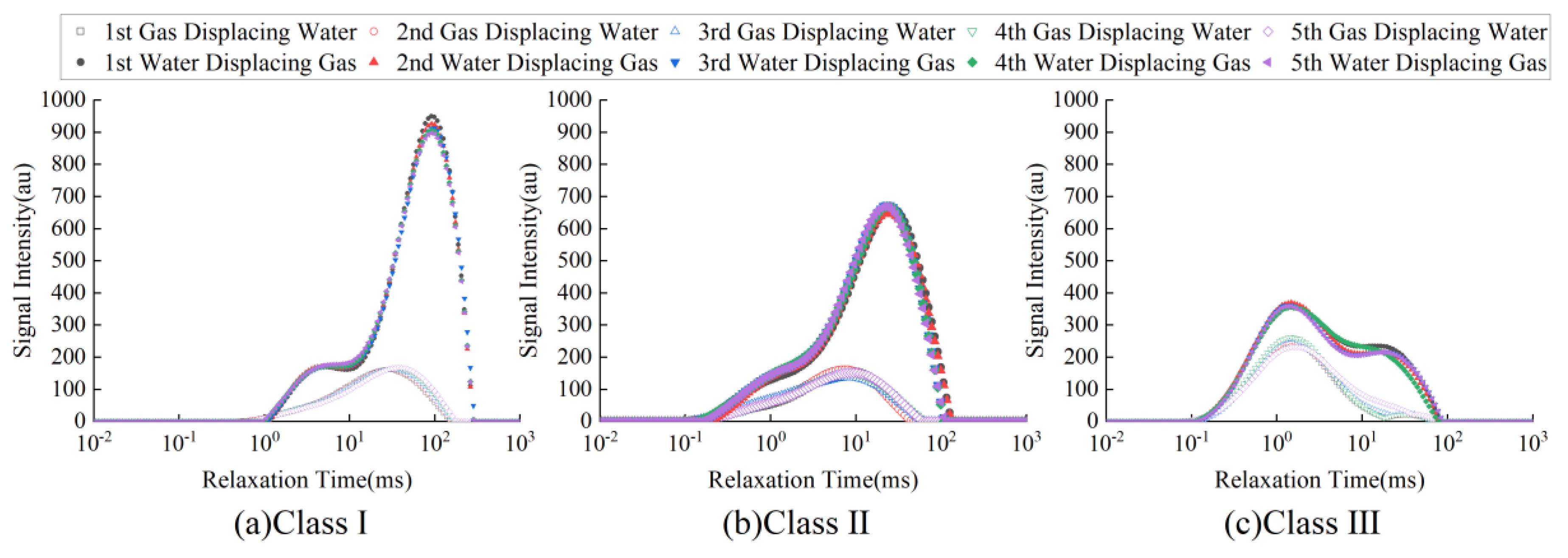
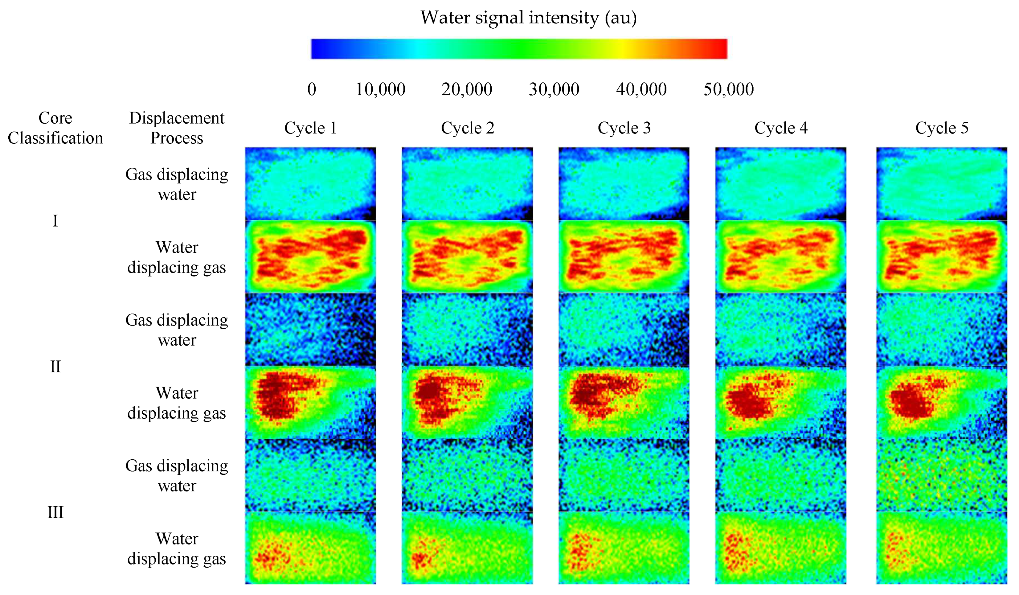
3.2. Multi-Cycle Gas–Water Mutual Drive Experiment Results

Through multi-cycle gas–water mutual drive experiments, the T2 spectra of the cores from the three reservoir types during the gas–water displacement and water–gas displacement processes were obtained (Figure 4), as well as the distribution maps of bound water and bound gas saturations (Figure 5) and the relationship between formation fluid saturation and displacement cycles (Figure 6).
The T2 spectra from the multi-cycle gas–water mutual drive experiments for the three pore structure types are shown in Figure 4. The distribution of the core’s nuclear magnetic resonance (NMR) signal intensity is shown in Figure 5 (in Figure 5, bluer colors indicate weaker NMR signals, representing lower water content; redder colors indicate stronger signals, representing higher water content). From Figure 4 and Figure 5, it can be seen that the Class I reservoir had better physical properties and higher permeability, with longer NMR relaxation times. During gas–water displacement, the core had a low water content and low bound water saturation. During water–gas displacement, the core’s water content was higher, and the bound gas saturation was low. The T2 spectra for gas–water displacement shifted to the right from the first to the fifth cycle, with an increase in relaxation time and stronger NMR signals, indicating that bound water saturation increased after multiple cycles of gas–water displacement. The T2 spectra for water–gas displacement shifted to the left, with a decrease in relaxation time and weaker signals, indicating a decrease in pore water saturation and an increase in bound gas saturation after water–gas displacement.
For Class II and Class III reservoirs, with lower permeability, the NMR relaxation times were shorter. After gas–water displacement, the water content was higher, and bound water saturation was higher. After water–gas displacement, the water content decreased, and bound gas saturation increased. The T2 spectrum changes for Class II and Class III reservoirs were more pronounced than for Class I, which is related to their lower permeability and stronger heterogeneity.
Movable space is defined as the pore space minus the bound water and bound gas saturation, representing the proportion of space that natural gas can be injected or produced from. A higher value indicates a larger effective storage and recovery space.
From Figure 6a, it can be seen that after five cycles of gas–water mutual drive, the bound gas saturation for Class I, II, and III reservoirs was 5.80%, 7.08%, and 22.42%, respectively, with increases of 8.01%, 14.19%, and 15.21% compared to the first cycle. From Figure 6b, the bound water saturation for Class I, II, and III reservoirs was 21.12%, 23.41%, and 41.05%, with increases of 5.07%, 4.04%, and 9.85%, respectively. Figure 6c shows that after five cycles, the movable space for Class I, II, and III reservoirs was 73.08%, 69.51%, and 36.53%, respectively, with decreases of 73.08%, 69.51%, and 36.53% compared to the first cycle. It is evident that the low-permeability reservoir’s gas–water mutual drive is significantly impacted by flow retardation, leading to a reduction in storage space.
Additionally, Figure 6 shows that the changes in bound water saturation, bound gas saturation, and movable space were more significant during the first three cycles, with minimal changes in the last two cycles. In summary, for Class I and II reservoirs (permeability > 80 mD), the impact of flow retardation during multi-cycle gas–water mutual drive was minimal and can be ignored. However, for Class III reservoirs (permeability < 5 mD), the impact of flow retardation on the reduction in movable space was significant and must be considered.
We have also constructed a quantitative model for predicting drainage efficiency based on rock properties. The fitting formulas for the changes in bound gas and bound water during each displacement process for the three types of reservoirs are as follows:
S g r I = 5.4852 + 0.2065 ln T 0.4305
S g r II = 6.3151 + 0.4974 ln T 0.2024
S g r III = 20.2703 + 1.4378 ln T 0.4315
S w r I = 37.4784 + 14.3554 ln T + 54.2196
S w r II = 22.5606 + 0.5538 ln T + 0.1131
S w r III = 35.4465 + 3.2209 ln T + 0.8033
In Equations (1)–(6), the following hold:
T—displacement cycle, dimensionless;
Sgr—Bound Gas Variation Rate, %;
Swr—Bound Water Variation Rate, %.

4. Discussion

4.1. Relationship Between Core Pore Structure and Gas–Water Mutual Drive

The pore structure characteristics of core samples, including pore size, connectivity, and morphology, play a crucial role in the gas–water mutual drive process. Experimental results show that the pore structure directly impacts the fluid displacement efficiency during both gas–water and water–gas displacement, thus determining the overall gas–water mutual drive effectiveness. The following discusses the specific influence of pore size, pore connectivity, and pore morphology on the gas–water displacement process:
  • Influence of Pore Size on Displacement Process
Pore size is a key factor influencing fluid mobility. During gas–water displacement, larger pores provide a wider flow path for the gas, allowing the gas to quickly replace the water, thereby increasing the displacement efficiency. Class I cores, which have larger pores and higher porosity, show higher gas–water displacement efficiency. In contrast, small pores or micropores restrict gas flow, leading to reduced gas–water displacement efficiency. In the water–gas displacement experiment, cores with larger pores can effectively push gas forward, improving displacement efficiency, while smaller pores or micropores may cause gas retention, thus lowering displacement efficiency.
2.
Influence of Pore Connectivity on Displacement Process
Pore connectivity determines the migration path and flow rate of fluids. Good pore connectivity helps improve gas–water mutual drive efficiency, particularly in the gas–water displacement process, where gas can flow smoothly through the core and rapidly replace the water. Class I cores, with good pore connectivity, demonstrate higher gas–water replacement efficiency during gas–water displacement. In cores with poor pore connectivity, gas or water flow is restricted, leading to lower displacement efficiency. In Class II and III cores, due to their heterogeneous pore structures, gas–water flow is significantly impeded, and gas retention is more pronounced, further reducing displacement efficiency.
3.
Influence of Pore Morphology on Displacement Process
Pore morphology plays an important role in the fluid flow path and distribution. Cores with regular and uniform pore morphology provide a more stable flow path, resulting in better fluid flow and higher displacement efficiency during the gas–water miscible process. Class I cores, with pores mainly consisting of residual intergranular pores and particle dissolution pores, have more uniform pore morphology, which benefits the gas–water replacement process. In contrast, Class II and III cores have more irregular pore morphology, with numerous small pores and filling material, resulting in poor fluid mobility and lower gas–water displacement efficiency.

4.2. Influence of Rock Physical Property Differences on Gas–Water Mutual Drive

The physical parameters of the core, such as permeability and porosity, directly influence the fluid migration and replacement efficiency in the gas–water mutual drive process. Different rock physical properties exhibit significant behavior differences due to variations in pore structure and fluid flow characteristics. By analyzing the impact of permeability, porosity, and other physical parameters on gas–water displacement, the behavior differences and their effect on displacement efficiency in cores with different physical properties can be revealed.
  • Influence of Permeability on Gas–Water Mutual Drive
Permeability is a key parameter describing the ability of the core to allow fluid flow. During gas–water displacement, high-permeability cores (such as Class I cores) provide smooth fluid flow paths, allowing gas to quickly replace the water and improving displacement efficiency. Low-permeability cores (such as Class III cores) restrict gas flow, leading to lower displacement efficiency. During water–gas displacement, high-permeability cores can effectively push gas forward, while low-permeability cores cause gas retention and reduce displacement efficiency. Therefore, cores with higher permeability exhibit better gas–water mutual drive performance.
2.
Influence of Porosity on Gas–Water Mutual Drive
Porosity only represents the space for fluid storage in the core. High porosity alone is not enough to predict efficiency. There can be a core with high porosity, but these pores are not interconnected at all. For this system, the displacement efficiency will become zero. In the gas-displacing-water process, cores with higher porosity (such as Class I cores) can accommodate more gas. Coupled with their higher connectivity, the gas–water replacement process is more efficient. Cores with high porosity and high connectivity provide more fluid channels, making the gas–water replacement process more uniform and rapid. In contrast, cores with lower porosity (such as Class III cores) have restricted fluid migration, the gas–water replacement process is slower, the irreducible water saturation is higher, and the displacement efficiency is lower.
3.
Relationship Between Heterogeneity of Pore Structure and Displacement Efficiency
The heterogeneity of pore size leads to significant differences in the flow paths and velocities of fluids in the core. Larger pores provide smoother flow channels for gas and water, making the gas–water mutual drive process more efficient. However, when a large number of micropores exist in the pore structure, these micropores will restrict the fluidity of the fluid, causing gas or water to be retained in the pores, thereby reducing the displacement efficiency. For example, the pore radius of Class I reservoir core is larger and evenly distributed, and the displacement efficiency of gas driving water and water driving gas is higher; while the pore radius of Class III reservoir core is smaller and unevenly distributed, the displacement efficiency is significantly reduced.
The heterogeneity of pore morphology also affects the efficiency of gas–water mutual drive. Regular and uniform pore morphology can provide stable flow channels, making the gas–water mutual drive process more efficient. Irregular pore morphology will increase the complexity of fluid flow and lead to a decrease in gas–water substitution efficiency. For example, the pore morphology of Class I reservoir core is relatively uniform, mainly composed of dissolution pores and intergranular pores, so the gas–water mutual drive efficiency is relatively high, while the pore morphology of Class II and Class III reservoir cores is more complex, with a large number of fillers and micropores, resulting in a lower drive–replacement efficiency.
The heterogeneity of the micropore structure, such as the presence or absence of fractures, also has an important impact on the displacement efficiency. Fractures can significantly improve the fluidity of fluids and increase the displacement efficiency. However, when fractures are connected to micropores, it may lead to the rapid flow of fluids in fractures while the fluids in micropores are retained, thus reducing the overall displacement efficiency. In the experiment, core samples of Class I reservoirs, due to their good microstructures and low heterogeneity, exhibit a relatively high displacement efficiency; core samples of Class III reservoirs, due to their complex microstructures and high heterogeneity, have a relatively low displacement efficiency.

4.3. Influence of Mineral Composition on Gas–Water Mutual Drive

Clay minerals and other mineral components in the core significantly affect the distribution of trapped gas and trapped water during gas flooding and water flooding processes. For Class I high-permeability reservoirs (permeability ≥ 100 mD), the clay content is low (3.1–4.2%), mainly dominated by large pores (average radius 39.95–49.81 μm), with good connectivity. The saturation of trapped water (20.1–21.1%) and trapped gas (5.4–5.8%) is the lowest. For Class III low-permeability reservoirs (permeability < 20 mD), the clay content is high (6.4–8.3%), and the proportion of micropores reaches 35–46.9%. Hydrophilic minerals such as illite and kaolinite enhance the capillary force through the adsorbed water film, and the flaky structure of chlorite hinders gas flow, resulting in a significant increase in the saturation of trapped water (37.4–41.1%) and trapped gas (19.5–22.4%). Class II medium-permeability reservoirs (20–100 mD) show transitional characteristics. After multi-cycle injection and production, reservoirs rich in clay minerals have more obvious attenuation of movable space due to micropore water retention and increased heterogeneity (decreasing from 43.2% to 36.5% for Class III, while only decreasing by 1.4% for Class I). The large pore structure supported by quartz and feldspar can reduce fluid retention. High-permeability and low-clay mineral reservoirs should be preferentially selected for the optimization of gas storage reservoirs.

4.4. Comparison with Research Results of Others

Khan pointed out that the heterogeneity of permeability leads to differences in gas–water flow paths, and this heterogeneity will have a serious impact on the recovery rate [22]. Cecilia demonstrated that in clay-rich rocks, the expansion of montmorillonite clay can reduce the effective porosity by as much as 18%, creating preferential flow paths and thus aggravating the heterogeneity of displacement [23]. AlKharraa reported that, compared with carbonate rocks, the displacement efficiency of clay-rich sandstones is 15–20% lower. This is mainly due to the presence of clay minerals increasing the bound water saturation [24]. By comparing with the existing literature, the experimental results of this study have been verified.

5. Conclusions

This study innovatively combines online nuclear magnetic resonance (NMR) technology with core experiments to reveal the impact of rock property differences (such as in permeability, porosity, and pore structure) on the gas–water mutual drive process. Notably, in low-permeability reservoirs, the core’s pore structure and microscopic features (such as fractures) significantly affect the gas–water distribution and displacement efficiency.
The study finds that rock heterogeneity leads to lower gas–water displacement efficiency, particularly in rocks with poor pore connectivity. In these cases, fluid distribution is uneven, complicating the displacement process. The combination of CT scanning and NMR technology allows for more accurate analysis of rock pore structures and their effects on gas–water displacement.
Future research should further explore the gas–water displacement effects in cores with different lithologies, optimize gas storage and extraction in reservoirs, and focus on long-term stability to improve the efficiency and sustainability of gas reservoirs.

Author Contributions

Conceptualization, J.P.; methodology, J.P.; formal analysis, H.C.; investigation, C.Z.; resources, J.P.; data curation, J.G.; writing—original draft preparation, T.W.; writing—review and editing, T.W.; supervision, X.Y.; project administration, X.Y. All authors have read and agreed to the published version of the manuscript.

Funding

This work was supported by the Key Projects of Scientific and Technological Research of Chongqing Municipal Education Commission “Study on the seepage law and injection-production capacity of gas storage reservoirs in complex double-layer carbonate rock water-invaded gas reservoirs” [grant numbers KJZD-K202401507].

Data Availability Statement

All data included in this study are available upon request by contact with the corresponding author.

Acknowledgments

We thank Chongqing Shale Gas Company for providing the experimental samples for this study, and thank Hong Liu of Chongqing University of Science and Technology for his contribution to the development of this research experiment.

Conflicts of Interest

The authors declare no conflicts of interest.

References

  1. Wang, Q.; Zhang, M.; Zhou, F.; Fei, H.; Yu, S.; Su, H.; Liang, T.; Chen, Z. Experiment and Prediction of Enhanced Gas Storage Capacity in Depleted Gas Reservoirs for Clean Energy Applications. Renew. Energy 2024, 237, 121894. [Google Scholar] [CrossRef]
  2. Yang, H.; He, Q.; Chao, M.; Ping, Z.; Li, H.; Yu, F.; Renze, L.; Li, Z.; Duan, C. Injection-mining scheme optimization of underground gas storage based on agent model. Geoenergy Sci. Eng. 2024, 244, 213406. [Google Scholar] [CrossRef]
  3. Mao, S.; Chen, B.; Malki, M.; Chen, F.; Morales, M.; Ma, Z.; Mehana, M. Efficient prediction of hydrogen storage performance in depleted gas reservoirs using machine learning. Appl. Energy 2024, 361, 122914. [Google Scholar] [CrossRef]
  4. Ramey, H.J. Correlations of Surface and Interfacial Tensions of Reservoir Fluids; Society of Petroleum Engineers: Richardson, TX, USA, 1973. [Google Scholar]
  5. Khalil, Z.; Saad, M. On a fully nonlinear degenerate parabolic system modeling immiscible gas–water displacement in porous media. Nonlinear Anal. -Real World Appl. 2011, 12, 1591–1615. [Google Scholar] [CrossRef]
  6. Zhang, R.; Liu, S. Experimental and theoretical characterization of methane and CO2 sorption hysteresis in coals based on Langmuir desorption. Int. J. Coal Geol. 2017, 171, 49–60. [Google Scholar] [CrossRef]
  7. Hamza, A.; Hussein, I.A.; Al-Marri, M.J.; Mahmoud, M.A.; Shawabkeh, R.A.; Aparicio, S. CO2 enhanced gas recovery and sequestration in depleted gas reservoirs: A review. J. Pet. Sci. Eng. 2021, 196, 107685. [Google Scholar] [CrossRef]
  8. Dabbaghi, E.; Ng, K.W. Effects of CO2 on the mineralogy, mechanical, and transport properties of rocks. Renew. Sustain. Energy Rev. 2024, 199, 114519. [Google Scholar] [CrossRef]
  9. Wang, Y.D.; Armstrong, R.T.; Mostaghimi, P. Enhancing resolution of digital rock images with super resolution convolutional neural networks. J. Pet. Sci. Eng. 2019, 182, 106261. [Google Scholar] [CrossRef]
  10. Niu, Y.; Jackson, S.J.; Alqahtani, N.; Mostaghimi, P.; Armstrong, R.T. Paired and unpaired deep learning methods for physically accurate super-resolution carbonate rock images. Transp. Porous Media 2022, 144, 825–847. [Google Scholar] [CrossRef]
  11. Buono, G.; Caliro, S.; Macedonio, G. Exploring microstructure and petrophysical properties of microporous volcanic rocks through 3D multiscale and super-resolution imaging. Sci. Rep. 2023, 13, 6651. [Google Scholar] [CrossRef]
  12. Fang, F.; Shen, W.; Gao, S.; Liu, H.; Wang, Q.; Li, Y. Experimental Study on the Physical Simulation of Water Invasion in Carbonate Gas Reservoirs. Appl. Sci. 2017, 7, 697. [Google Scholar] [CrossRef]
  13. Lu, Z.; Sha, A.M.; Wang, W.T. Permeability evaluation of clay-quartz mixtures based on low-field NMR and fractal analysis. Appl. Sci. 2020, 10, 1585. [Google Scholar] [CrossRef]
  14. Liu, Z.; Gu, Q.; Yang, H.; Liu, J.; Luan, G.; Hu, P.; Yu, Z. Gas–Water Two-Phase Displacement Mechanism in Coal Fractal Structures Based on a Low-Field Nuclear Magnetic Resonance Experiment. Sustainability 2023, 15, 15440. [Google Scholar] [CrossRef]
  15. Liu, S.; Zhang, Y.; Zhao, Y.; Wang, Z.; Song, Y.; Lv, J. Study of displacement behavior and dispersion characteristics based on low-field NMR in the context of CO2 geological sequestration and enhanced methane recovery. Fuel 2024, 373, 132332. [Google Scholar] [CrossRef]
  16. Gu, J.; Lyu, H.; Chen, G. Research on the characteristics of pore water distribution of calcium carbonate waste soil based on NMR tests. Bull. Eng. Geol. Environ. 2025, 84, 60. [Google Scholar] [CrossRef]
  17. Liu, Z.; Zhu, M.; Yang, H.; Hu, P.; Gu, Q. Dynamic evolution process and application of gas displacement by water injection in gas-bearing coal bodies. Int. J. Heat Mass Transfer. 2024, 224, 125352. [Google Scholar] [CrossRef]
  18. Cong, Y.; Zhai, C.; Yu, X.; Xu, J.; Sun, Y. Quantification of liquid nitrogen injection efficiency and phase change expansion boost laws in coal seam borehole. Int. J. Heat Mass Transfer. 2024, 220, 125010. [Google Scholar] [CrossRef]
  19. Xue, Y.; Liu, J.; Liang, X.; Wang, S.; Ma, Z. Ecological risk assessment of soil and water loss by thermal enhanced methane recovery: Numerical study using two-phase flow simulation. J. Clean. Prod. 2021, 334, 130183. [Google Scholar] [CrossRef]
  20. Huang, Z.; Li, X.; Li, S.; Zhao, K.; Zhang, R. Investigation of the hydraulic properties of deep fractured rocks around underground excavations using high-pressure injection tests. Eng. Geol. 2018, 245, 180–191. [Google Scholar] [CrossRef]
  21. Kozhevnikov, E.; Turbakov, M.; Riabokon, E.; Gladkikh, E.; Guzev, M. Rock permeability evolution during cyclic loading and colloid migration after saturation and drying. Adv. Geo-Energy Res. 2024, 11, 208–219. [Google Scholar] [CrossRef]
  22. Khan, M.Y.; Mandal, A. The impact of permeability heterogeneity on water-alternating-gas displacement in highly stratified heterogeneous reservoirs. J. Pet. Explor. Prod. Technol. 2022, 12, 871–897. [Google Scholar] [CrossRef]
  23. Cecilia, J.A.; García-Sancho, C.; Franco, F. Montmorillonite based porous clay heterostructures: Influence of Zr in the structure and acidic properties. Microporous Mesoporous Mater. 2013, 176, 95–102. [Google Scholar] [CrossRef]
  24. AlKharraa, H.; Wolf, K.H.; Alquraishi, A.A.; Mahmoud, M.A.; Deshenenkov, I.S.; AlDuhailan, M.A.; Alarifi, S.A.; Alqahtani, N.B.; Kwak, H.; Zitha, P.L. Impact of clay mineralogy on the petrophysical properties of tight sandstones. Geoenergy Sci. Eng. 2023, 227, 211883. [Google Scholar] [CrossRef]
Figure 1. Three-dimensional scanning images of core samples from different reservoir types.
Energies 18 01338 g001
Figure 2. Electron microscope scanning images of core samples from different reservoir types.
Energies 18 01338 g002
Figure 3. Three-dimensional confocal imaging of core samples from different reservoir types (red represents large pores, green represents micropores).
Energies 18 01338 g003
Figure 4. Gas-water mutual drive T2 spectra for three reservoir types.
Energies 18 01338 g004
Figure 5. NMR signal distribution of cores from different reservoir types during gas-water mutual drive.
Energies 18 01338 g005
Figure 6. Relationship between formation fluid saturation and displacement cycles for different reservoir types.
Energies 18 01338 g006
Table 1. Porosity, permeability, and clay content of core samples from different types of reservoirs.
Core ClassPermeability (mD)Porosity (%)Clay Content (%)
I≥100>20<5
II20–10015–205–15
III<20<15>15
Disclaimer/Publisher’s Note: The statements, opinions and data contained in all publications are solely those of the individual author(s) and contributor(s) and not of MDPI and/or the editor(s). MDPI and/or the editor(s) disclaim responsibility for any injury to people or property resulting from any ideas, methods, instructions or products referred to in the content.

