Review

Receiver-Side Topologies for Wireless Power Transfer Systems: A Comprehensive Review of the Design, Challenges, and Future Trends

1
School of Electric Engineering and Automation, Harbin Institute of Technology, Harbin 150001, China
2
Zhengzhou Research Institute, Harbin Institute of Technology, Zhengzhou 450003, China
*
Author to whom correspondence should be addressed.
Energies 2025, 18(6), 1493; https://doi.org/10.3390/en18061493
Submission received: 5 February 2025 / Revised: 14 March 2025 / Accepted: 16 March 2025 / Published: 18 March 2025
(This article belongs to the Special Issue Wireless Charging Technologies for Electric Vehicles)

Abstract

:
Expanding the application scenarios of wireless power transfer (WPT) systems demands increasingly stringent performance requirements. As a critical interface between the power source and load, the receiver topology plays a pivotal role in determining the system’s efficiency and stability. This review focuses on advancements in power electronic receiver designs for WPT systems, with an emphasis on two-stage and single-stage topologies. This article provides an overview of the current design status of power electronic topologies at the receiver in existing WPT systems, with a focus on analyzing the design ideas, implementation methods, and performance of two-stage and single-stage receivers. The advantages and disadvantages of various receiver topologies are discussed in detail, and corresponding strategies are proposed to address the new challenges associated with the stability of existing WPT systems.

1. Introduction

In recent years, with the development of technology and social progress, wireless power transfer (WPT) technology has gradually become integrated into people’s lives. WPT technology comprehensively utilizes electrical engineering theory, power electronics technology, and control theory and uses magnetic fields, electric fields, microwaves, and other carriers to transfer electrical energy from the grid or a battery to electrical equipment in a non-electrical-contact manner [1]. The basic principle of resonant WPT technology is to transmit electrical energy efficiently by causing magnetic coupling resonance between the coils of the transmitting and receiving ends at the same resonant frequency [2]. Owing to its wide power rating, high transmission efficiency, and minimal environmental impact, it has been used in multiple fields. After years of development, modeling, topology design, control, and other technologies based on resonant WPT systems have been gradually improved, enabling the successful application of WPT technology in the fields of new energy vehicles [3,4], consumer electronics [5,6], medical equipment [7,8], unmanned underwater vehicles [9,10], unmanned aerial vehicles [11,12], and aerospace [13,14].
However, as the application scenarios diversify and power demands escalate, receiver topologies face heightened requirements to achieve multidimensional optimization in terms of efficiency, dynamic responses, compactness, and cost-effectiveness.
A typical diagram of a WPT system is shown in Figure 1 [15,16,17]. The receiver plays an important role in this system, as it is responsible for transforming the high-frequency wireless transmission AC input power into DC power and providing a continuous DC current with good output regulation for the direct charging of the battery, seeking to ensure a stable and reliable load power supply.
The current receiver topologies primarily adopt two-stage or single-stage architectures. The two-stage configuration, which combines rectifiers with DC-DC converters, enables wide-range voltage regulation and high-precision output control. However, they suffer from component redundancy, reduced efficiency under light-load conditions, and stability challenges owing to parameter mismatches. In contrast, the single-stage design of a streamlined circuit integration must address critical issues such as harmonic suppression, dynamic load adaptability, and soft switching capabilities. Furthermore, in dynamic wireless charging (DWPT) scenarios, rapid fluctuations in the coupling coefficients exacerbate the tradeoff between system stability and power consistency. To address these challenges, recent academic efforts have focused on topological innovation, modulation strategies, and advanced control methodologies; however, a systematic framework for technical reviews and performance comparisons remains undeveloped.
Two-stage receivers are widely used in WPT systems, where the first stage is a rectifier and the second stage is a DC-DC converter. The function of a rectifier is to convert an AC current into a fixed or adjustable DC current; it is composed of silicon rectifier diodes or switches. The second stage is a DC-DC converter, whose core function is to perform the secondary regulation of the rectified DC voltage, ensuring the stability and accuracy of the output voltage, thereby providing reliable power for battery charging or other sensitive loads. In addition, DC-DC converters can dynamically adjust the output power according to load changes to adapt to different working conditions [18,19].
The core of a single-stage solution lies in the use of efficient and structurally simple rectifiers, such as Class E rectifiers [20,21], multi-level converters, active half-bridge rectifiers, or active full-bridge rectifiers. These rectifiers can directly convert AC currents into a stable DC output voltage and achieve the precise adjustment of the output voltage by controlling the magnitude of the AC input current. This design simplifies the system’s structure, reduces the use of components, lowers the system costs, and can improve the energy conversion efficiency. Therefore, single-stage rectifiers provide a more efficient, concise, and reliable alternative for WPT systems. The classification of existing WPT receivers is shown in Figure 2.
This study comprehensively reviews the latest advancements in WPT receiver topologies and provides an in-depth analysis of both topological paradigms from the perspectives of circuit design, modulation techniques, and control strategies. By evaluating the strengths and limitations of representative topologies, we synthesize their performance across key metrics, including efficiency, dynamic responses, and costs, and propose optimization pathways to address the challenges of system stability. This review aims to establish a theoretical foundation for high-performance WPT system design and illuminate potential trajectories for future technological evolution.
The main research content of this article is a summary of the receiver topologies and related control techniques currently applied in WPT systems and an analysis of the key issues in these topologies. Section 2 discusses the two-stage receivers of WPT systems. Section 3 discusses the single-stage receivers of WPT systems. Section 4 analyzes the critical techniques. Finally, future trends and prospects are discussed in Section 5, and the conclusions of this study are presented in Section 6.

2. Two-Stage Receivers

This section systematically evaluates two-stage receivers, which dominate high-power WPT applications due to their flexibility in voltage regulation.
Figure 3 shows the most commonly used receiver topology in WPT systems. It consists of four diodes that form a full-bridge rectifier circuit, which converts AC into DC to power the load. Moreover, capacitors are typically added to the output of the rectifier bridge to filter out high-frequency voltage ripples. A widely adopted design involves the selection of a sufficiently large capacitor to ensure a stable DC-link voltage. However, because this voltage remains unregulated, it may not align with the specific voltage requirements of the load. To address this, a second-stage DC-DC converter is employed to achieve both voltage matching and precise output voltage regulation [22].
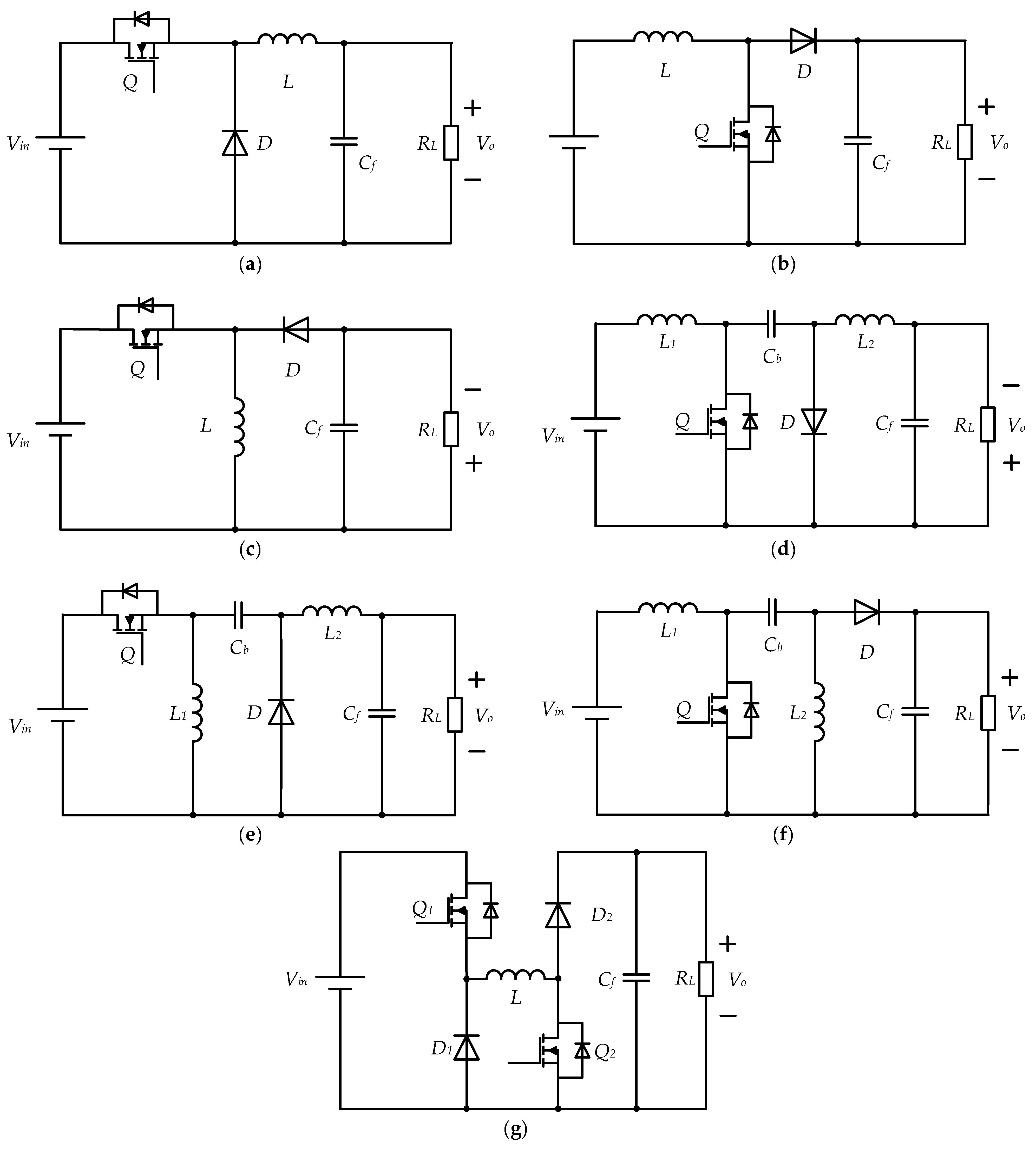
Common non-isolated DC-DC converters include buck converters, boost converters, single buck–boost converters, Cuk converters, zeta converters, SEPIC converters, and dual buck–boost converters, as shown in Figure 4 [23]. Among them, the input and output voltage polarities of buck–boost converters and Cuk converters are contrasting, and Cuk, zeta, and SEPIC converters are usually not conducive to improving the power density of the converters due to the large number of passive components. In addition, the dual-switch buck–boost converter is a specific type of buck–boost converter with the same polarity as the input and output voltages. In this converter, the voltage stress of switch Q1 and diode D1 is the input voltage Vin, whereas the voltage stress of switch Q2 and diode D2 is the output voltage Vo, respectively. A comparison of the five DC-DC converters is presented in Table 1 [23].
At present, buck converters are the most commonly used in WPT systems because of their simple control and high efficiency. If synchronous buck circuits are used, the losses of the diodes can be ignored, further improving the efficiency [24]. A typical WPT system with a buck converter at the receiver is shown in Figure 4a. The transmitting coil is driven by an AC current source, whereas the receiving coil is compensated in series by the capacitors. After rectification, a buck converter is connected to regulate the output current and voltage of the battery. A WPT system and buck converter form a typical cascaded system.
In previous studies, the selection of the regulating capacitor for the buck converter at the receiver part of the WPT system was mainly based on the consideration of the system’s start-up current and continuous working mode, but its impact on system stability has not been fully explored. Song et al. [25] filled this gap and revealed the system instability phenomenon, which may be caused by the improper selection of regulating capacitors, through theoretical analysis and experimental verification. Their research first established a cascade system model of the WPT system and buck and derived the output impedance of the buck front-end equivalent circuit and the input impedance of the buck. Research has found that the output impedance of WPT systems is directly related to the regulating capacitor Co, whereas buck converters exhibit negative resistance at low frequencies and inductance at high frequencies [26]. Based on the Middlebrook stability criterion, this study analyzes the stability conditions of cascaded systems and points out that adjusting the capacitance to a small value can lead to system instability. Specifically, a small adjustment capacitor increases the peak output impedance of the system as a whole, reduces the resonant frequency, and thus makes it easier to satisfy unstable conditions.
Tan et al. [27] proposed a novel control strategy to address the issue of insufficient system stability in the cascaded structures of WPT systems to improve the stability and dynamic performance of the system. A dynamic model of the system was established from the perspective of small-signal equivalent admittance, and the stability of the system was theoretically analyzed, proving the instability of the traditional control systems. The robustness of the impedance-shaping control strategy was verified by testing the dynamic response of the DC-DC converter when the output current reference value suddenly changed from 0 to 30 A. When the output current was 30 A, the efficiency of the system was approximately 85%. The experimental results showed that, even when the operating conditions and system parameters changed, this control strategy could maintain a fast dynamic response, small overshoot, and oscillation [28].
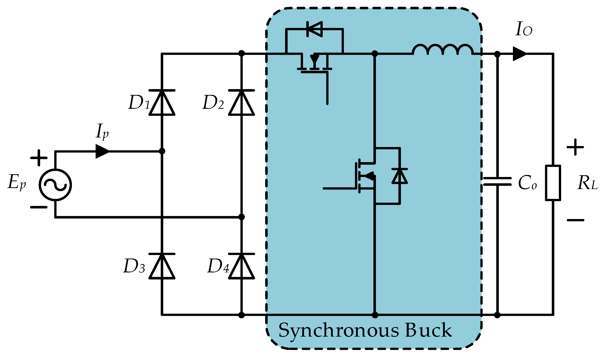
As mentioned earlier, replacing the diode in the buck circuit with a switch and setting its duty cycle opposite to the original switch can achieve the function of the original diode and significantly reduce the losses, i.e., creating a synchronous buck circuit. Therefore, the buck circuit of the receiver in the WPT system is changed to a synchronous buck circuit, as shown in Figure 5. Moreover, by adding a dual voltage controller, the inner loop is used to stabilize the input voltage, and the outer loop adjusts the output voltage [29], which can solve the problem of the large capacitance adjustment mentioned earlier and improve the dynamic performance and stability of the WPT system [30,31].
One of the main challenges faced by DWPT in practical applications is the fluctuation in the output power. This fluctuation is mainly caused by changes in the coupling coefficients between vehicles and charging facilities, leading to unstable power transmission, which affects the battery life and charging efficiency. Song et al. [32] adopted a dual-input buck converter, as shown in Figure 6, combined with a constant-impedance control strategy. The core of the constant-resistance (CR) control strategy is to adjust the phase of the input current to maintain consistency with the input voltage, thereby achieving uniform power transmission. This control strategy not only effectively reduces power fluctuations but also achieves a stable power output at the receiver side, maintaining good performance even under changes in vehicle speed. The researchers constructed a 1.5 kW experimental platform, and the experimental results showed that the fluctuation factors of the output power were 1.37%, 3.19%, and 4.69% at speeds of 10, 40 km/h, and 100 km/h, respectively. This indicates that the system can maintain a stable power output even under wide speed ranges and non-ideal conditions.
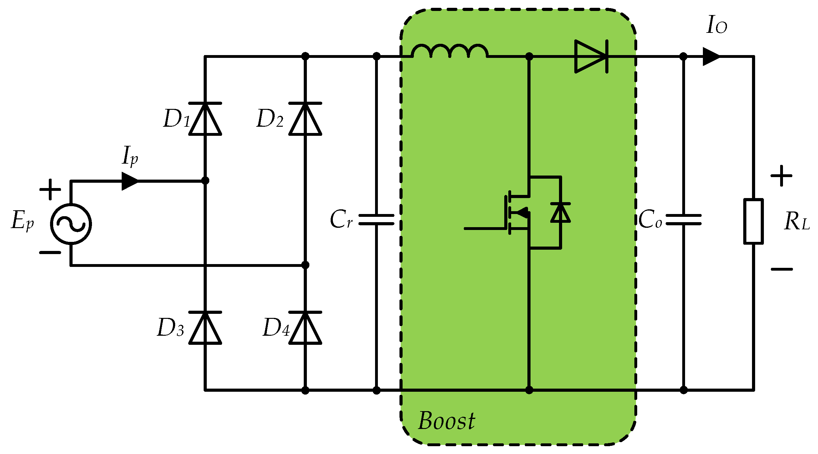
Under dynamic operating conditions, the current stress problem at the receiver side (such as the peak resonance current and inductor current) becomes particularly prominent; this not only affects the reliability of the system but may also lead to insulation failures and high capacitor voltages. To address this issue, Song et al. [33] proposed a solution based on CR control. By adding a boost converter, as shown in Figure 7, the current stress was alleviated while maintaining efficient energy transfer. A current model for the receiver of a DWPT system was established, and the phenomenon of current stress deterioration with increasing speed under constant-current control was analyzed. The researchers designed a series of experiments, and the results showed that, under non-ideal coupling conditions (such as unequal coupling, non-orthogonal coupling, and non-sinusoidal coupling), the maximum stress improvement rate reached 44%.
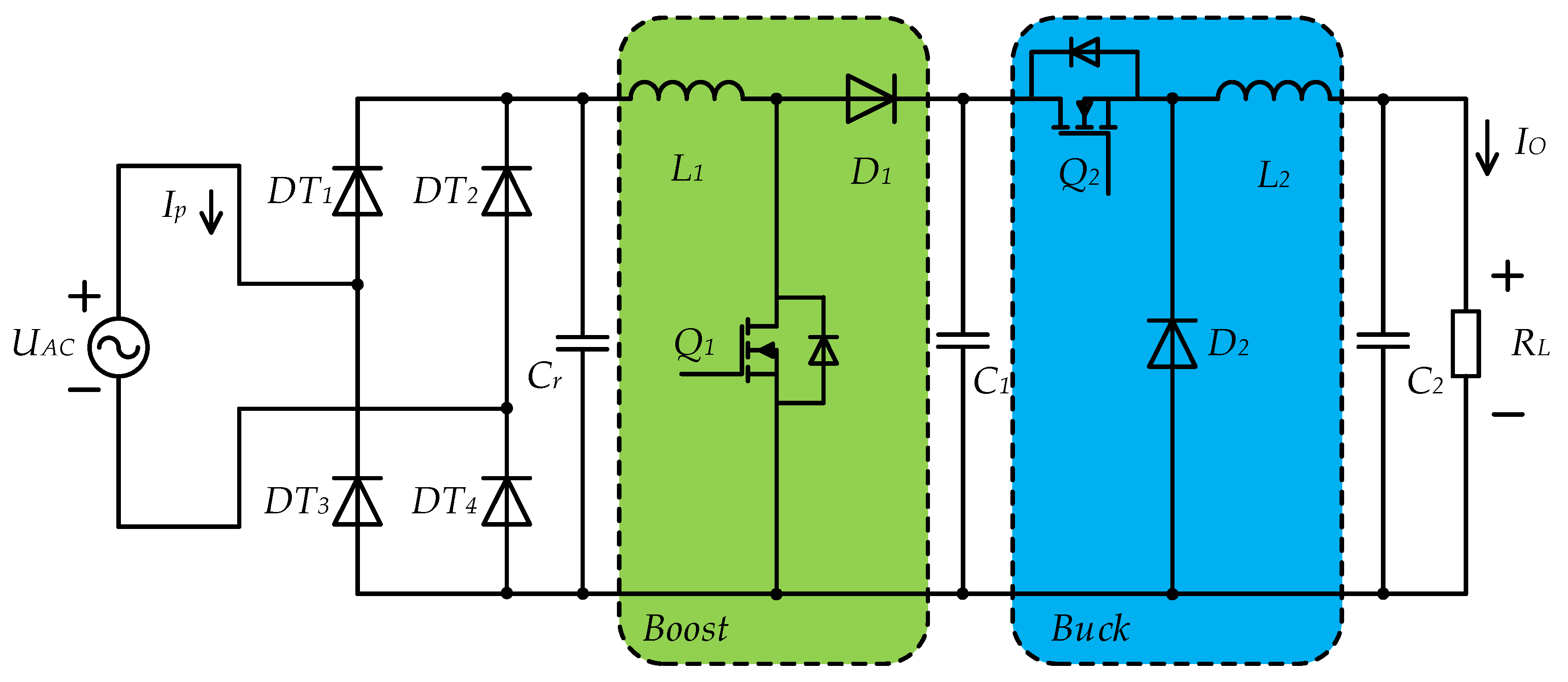
Owing to the nonlinear characteristics of rectifiers, it is difficult to obtain the optimal load resistance through analytical expressions, and adjusting the load resistance cannot achieve optimal impedance matching. Cascaded boost–buck converters have been used to achieve impedance matching, as shown in Figure 8 [34]. Boost converters are easy to control owing to their continuous input current feedback, whereas buck converters are widely used for battery charging and power management. This cascaded structure not only achieves optimal impedance matching but can also dynamically adjust or adapt to changing load conditions, thereby improving the overall efficiency of the system.
The cascaded boost–buck converter achieves dynamic load adaptation through dual closed-loop cooperative control: the front-end boost calculates the impedance deviation in real time based on the input voltage/current and maintains coil resonance matching by adjusting the duty cycle through PI to reduce power reflection; the rear-stage buck dynamically adjusts the duty cycle to compensate for load transients by tracking the buffer capacitor voltage (preset as a fixed multiple of the input voltage) while reversing the front-stage duty cycle, forming a two-stage decoupling coupling control mechanism. Fu et al. [34] tested a 13.56 MHz WPT system and confirmed that the control mechanism could increase the system efficiency from 64% to 74% in battery charging scenarios and achieve an efficiency jump from 23% to 73% in supercapacitor charging.
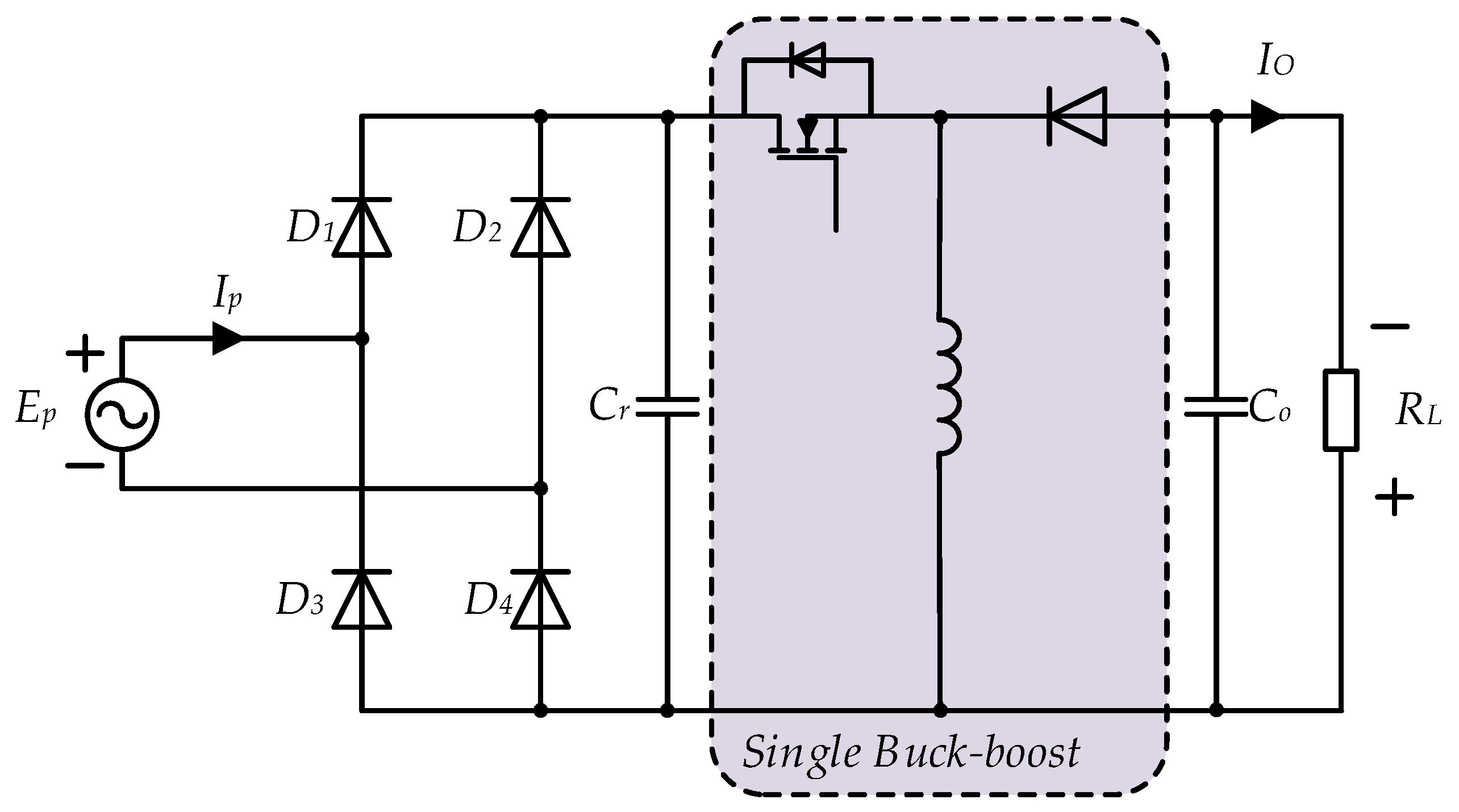
Combining boost and buck circuits to form a buck–boost circuit for use in receivers in WPT systems can enable the precise adjustment of the output voltage, as shown in Figure 9, which is crucial in protecting loads from the effects of high voltage overshoot. The maximum energy efficiency can be achieved by simulating the optimal load value, and the dynamic performance of the system can be improved. In addition, the buck–boost converter simplifies the system design, reduces the hardware requirements, and supports multiple load types, further enhancing the versatility and adaptability of the WPT system. These characteristics render the buck–boost converter a crucial component in realizing efficient and dynamically stable WPT systems, thereby significantly enhancing the overall performance and reliability of the system [35]. Yang et al. [36] proposed a discrete sliding mode control (DSMC) scheme to replace the traditional discrete proportional–integral (PI) control. The experimental results of its construction showed that the DSMC reduced the overshoot of the output voltage by approximately 16.6% and shortened the stabilization time by approximately 72.9%.
Hu et al. [37] proposed another closed-loop control scheme to achieve maximum-efficiency tracking and a stable output voltage. This scheme uses two DC-DC converters: one is used at the front-end inverter to track the maximum efficiency point, and the load resistance is adjusted to match the optimal value. The other is located at the rear receiver part to regulate the input voltage of the transmitting end and maintain the stability of the output voltage of the system. Through real-time mutual inductance estimation and a closed-loop control strategy, maximum-efficiency tracking and a stable output voltage were achieved under dynamic conditions of mutual inductance and load changes.
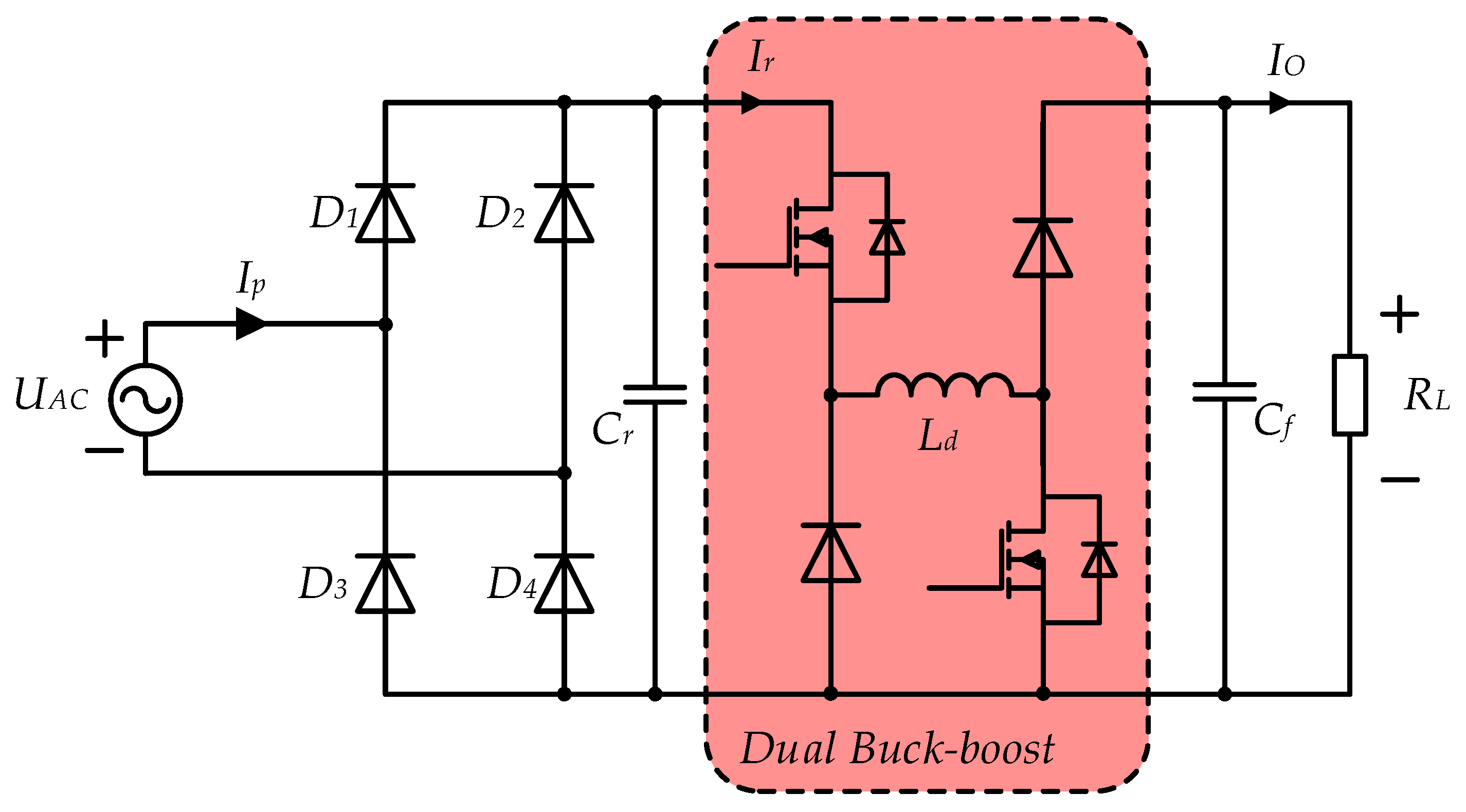
Owing to issues such as high switching stress and the opposite polarity of the input and output in a single-switch buck–boost circuit, a dual-switch buck–boost converter is used, as shown in Figure 10 [38]. Using a dual-mode dual-edge modulation switching control strategy [39], the converter is efficiently controlled by independently adjusting the conduction time and duty cycle of the two switches. This effectively reduces the inductor current ripple and average current, thereby reducing component losses and improving the overall efficiency.
Based on traditional dual-edge modulation, Zhang et al. [38] separately adjusted the duty cycles of two switching transistors to achieve asynchronous control. When the input voltage fluctuates, maintaining the duty cycle of one of the switching transistors can significantly reduce the fluctuations in the inductor current il and output current io and significantly improve the efficiency of DC-DC converters. The experimental results demonstrate that the proposed asynchronous control strategy achieves peak efficiency of 95.57%, representing an improvement of approximately 4% over conventional control methods.
Compared with traditional buck, boost, and single buck–boost converters, dual buck–boost converters have a wider voltage conversion range, lower switching voltage stress, lower output fluctuations, and higher stability under asynchronous control, making them more suitable for DWPT systems. However, at the same time, this also increases the complexity and control difficulty of the system.
The two-stage structure of the receiver is a combination of a traditional four-diode rectifier and a DC-DC converter. Therefore, applying various types of topologies in power electronic DC-DC converters to WPT systems is a wise choice, especially in DWPT systems. Owing to the large variation in the mutual inductance parameters in the coupling mechanism, the various parameters of the system change significantly, which strongly affects the dynamic response capabilities of the system. The topological performance of the two-stage structures applied to the WPT system receiver is compared in Table 2.

3. Single-Stage Receivers

The single-stage receiver circuit has some obvious advantages over the two-stage receiver circuit, such as fewer components and no need to match the resonant frequency of the WPT system with the switching frequency of the DC-DC converter [40]. The mainstream topology of the current wireless power receivers primarily adopts a full-bridge or semi-active full-bridge structure design. Although this topology has the advantage of simple circuits, it has significant limitations in high-current-output scenarios. First, the discontinuous DC output characteristics of the bridge structure rely on large-volume filtering capacitors to maintain a stable load current, and the high current stress borne by the output capacitors limits the maximum output capacity of the system [41,42,43,44,45,46,47,48]. Second, the direct short-circuit risk of the full-bridge structure imposes strict requirements on the dead-time design of the high- and low-side gate drives. Third, the inherent voltage-doubling characteristics of half-bridge or semi-active half-bridge receivers limit their output voltage regulation ranges, making it difficult to adapt them to high-voltage-output applications [49,50].
Single-switch resonant wireless power receivers have been proposed to overcome these issues, such as in the bidirectional WPT system in Li’s work [51,52]. This scheme has gained attention because of its simple circuit, easy implementation of driving, and natural soft switching characteristics, but the second harmonic current generated in the wireless coil reduces the efficiency. First, it increases the loss of the switches. The superposition of high-frequency harmonics and the fundamental current exacerbates conduction losses and transient losses caused by soft switch failure. The second is the deterioration of the magnetic components’ performance, where harmonic currents lead to an increase in copper and iron losses through the skin effect and magnetic core losses (such as eddy currents and hysteresis); this also causes resonance detuning, which disrupts system impedance matching and reduces the energy transmission efficiency [53]. In addition, the significant base current component in the output inductance forces the system to configure large-capacity capacitors to suppress output voltage ripples.
In terms of exploring innovative topologies, some studies have integrated full-bridge diode rectifiers with interleaved parallel buck converters using a hybrid pulse width modulation (PWM) and phase-shift modulation (PSM) coordinated control strategy to achieve input current synchronization, efficient energy conversion, and precise voltage regulation [54,55]. The smooth output current characteristics inherited by the interleaved parallel architecture are beneficial for current expansion in high-power scenarios, but the consistency and reliability issues of its magnetically integrated components have not been fully resolved, and the control complexity brought about by the hybrid modulation strategy has significantly increased, requiring the precise adjustment of the phase and duty cycle parameters of the PWM signal.
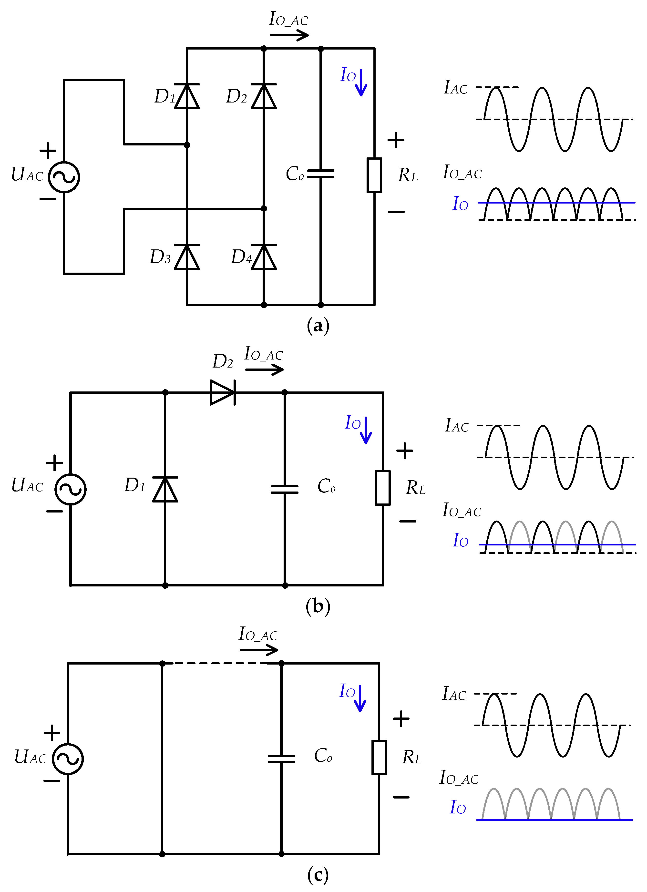
A novel topology integrating an N-level single-inductor multiple-output (SIMO) DC-DC converter, as shown in Figure 11 [56], with a multi-stage rectifier was proposed in [57]. Specifically, a prototype combining an active voltage doubler rectifier and a three-level single-inductor dual-output (SIDO) converter is presented. In general, regulating the rectifiers can control the rectified current using various techniques. One such control approach is PWM, which adjusts the duty cycle of the rectifier switches to implement different rectifier configurations, thereby modifying the impedance of the antenna.
The primary rectifier configurations are the 1×, 0.5×, and 0× modes, corresponding to a full-bridge rectifier, half-bridge rectifier, and antenna short-circuit, respectively. In addition, a 2× configuration can be implemented, which consists of two half-bridge rectifiers connected in series to form a voltage doubler. By switching between these configurations, the average rectified load current and, consequently, the output voltage can be regulated. For example, Li et al. [49] utilized 1×–2× configurations, Cheng et al. [50] employed 0×–0.5×–1× configurations, and Yang et al. [58] and Namgoong et al. [59] used 0×–1× configurations.
To achieve precise impedance matching and output voltage control, existing technologies include phase modulation [60,61], delay tuning [62], constant idle time control [59,63], reverse current injection [64], pulse frequency modulation (PFM) [65,66], and pulse skipping techniques [67]. Among these, hysteresis control is highly favored because of its fast dynamic response characteristics [59,68].
Significant progress has been made in the research of full-bridge active rectifiers in wide-voltage-range application scenarios. Serban et al. [69] used a bidirectional parallel-series dual active bridge (DAB) converter topology to achieve a high DC gain and expand the voltage range using parallel low-voltage bridges and series high-voltage transformer windings. Li et al. [70] proposed a segmented three-phase-shift (TPS) modulation scheme that achieved maximum-efficiency tracking and zero-voltage switching (ZVS) over a wide voltage range by switching between three operating modes. Li et al. [71] proposed a hybrid modulation control method that reduced the reactive power under light-load conditions by dynamically switching between full-bridge and half-bridge modes, thereby improving the efficiency. This scheme achieves ZVS operation while maintaining a constant output voltage, with experimental efficiency of 94.29%. In addition, the overall system performance can be further improved by reducing the reactive power, optimizing the magnetic component design, and adopting wide-bandgap semiconductor devices. The integration of these technologies provides a new solution for high-density power conversion over a wide voltage range, which is particularly suitable for dynamic load scenarios, such as the fast charging of electric vehicles.
Zhao et al. [72] proposed an adaptive synchronous driving phase control (ASDPC) method for a full-bridge rectifier based on gallium nitride (GaN) for a WPT system at 6.78 MHz, as shown in Figure 12. The ASDPC method aims to address the limitations of the traditional synchronous rectification technology at high frequencies. Although GaN switches have the advantages of fast switching and low resistance, their parasitic capacitance and reverse conduction loss are significantly amplified in high-frequency scenarios. It is difficult for traditional fixed dead time or silicon-based resonant rectification methods to dynamically adapt to load changes, resulting in a decrease in their efficiency. ASDPC adjusts the driving signal phase in real time to synchronize with the resonant current through dynamic dead time control (DDTC) and 400 MHz digital phase compensation, ensuring critical zero-voltage switching, eliminating reverse conduction losses, and simplifying the system design without the need for additional LC networks.
Compared with silicon-based systems, ASDPC has significant advantages in high-frequency scenarios. Traditional silicon-based methods rely on fixed dead zones or resonant networks, which have problems such as high switching losses and insufficient phase synchronization accuracy. ASDPC achieves wide load range (8–50 Ω) adaptation through a serial control structure (outer-loop DDTC and inner-loop phase compensation). Experiments show that its DC-DC efficiency reaches 87.18%, which is 3.1–5.2% higher than that of traditional solutions, and its dynamic response is faster, being especially suitable for the efficiency requirements of MHz-level high-frequency wireless charging.
Li et al. [73] proposed a maximum-efficiency point tracking control method based on pulse density modulation (PDM), where the receiver uses a half-bridge active rectifier, as shown in Figure 13. This method controls power transmission by adjusting the number of pulses, rather than the pulse width or frequency, thereby achieving soft switching and resonance tuning. The experimental results show that PDM can significantly improve the efficiency of the system, maintaining efficiency of over 70% even at very low coupling coefficients, while effectively regulating the output voltage and reducing the ripple. In addition, the bilateral soft switching technology further reduces switching losses and improves the overall efficiency of the system. This method is particularly suitable for high-frequency, weakly coupled WPT systems, such as in the active rectifier in Namgoong’s work [74].
Diekhans et al. [75] proposed a series–series compensation topology with bilateral power control and a corresponding control strategy, using a dual-switch active converter topology, as shown in Figure 14, to achieve bilateral power control without adding additional DC-DC converters to the system, thereby minimizing the additional hardware overhead. Its partial load efficiency at 500 W output power under a 100 mm air gap is as high as 95.8%. Overall, this topology is suitable for application scenarios that require high efficiency and a wide operating range. The adopted bilateral control strategy not only improves the overall efficiency of the system but also enhances its robustness and adaptability. Furthermore, through a bilateral control strategy based on mode switching, the transmission efficiency of the system can be further increased by approaching the optimal load impedance and zero-voltage switching of all MOSFETs in the WPT system [76,77].
The above three types of active rectifiers replace passive diodes with controllable switches to achieve dynamic current path control and soft switching operation. Their main advantages are as follows: the efficiency can be further improved and synchronous rectification technology can reduce conduction losses; they can achieve dynamic impedance matching and adjust the equivalent load impedance in real time to optimize the system resonance. Among them, full-bridge active rectifiers and half-bridge active rectifiers can achieve bidirectional power flow support and are suitable for energy feedback scenarios such as V2G and drone charging.
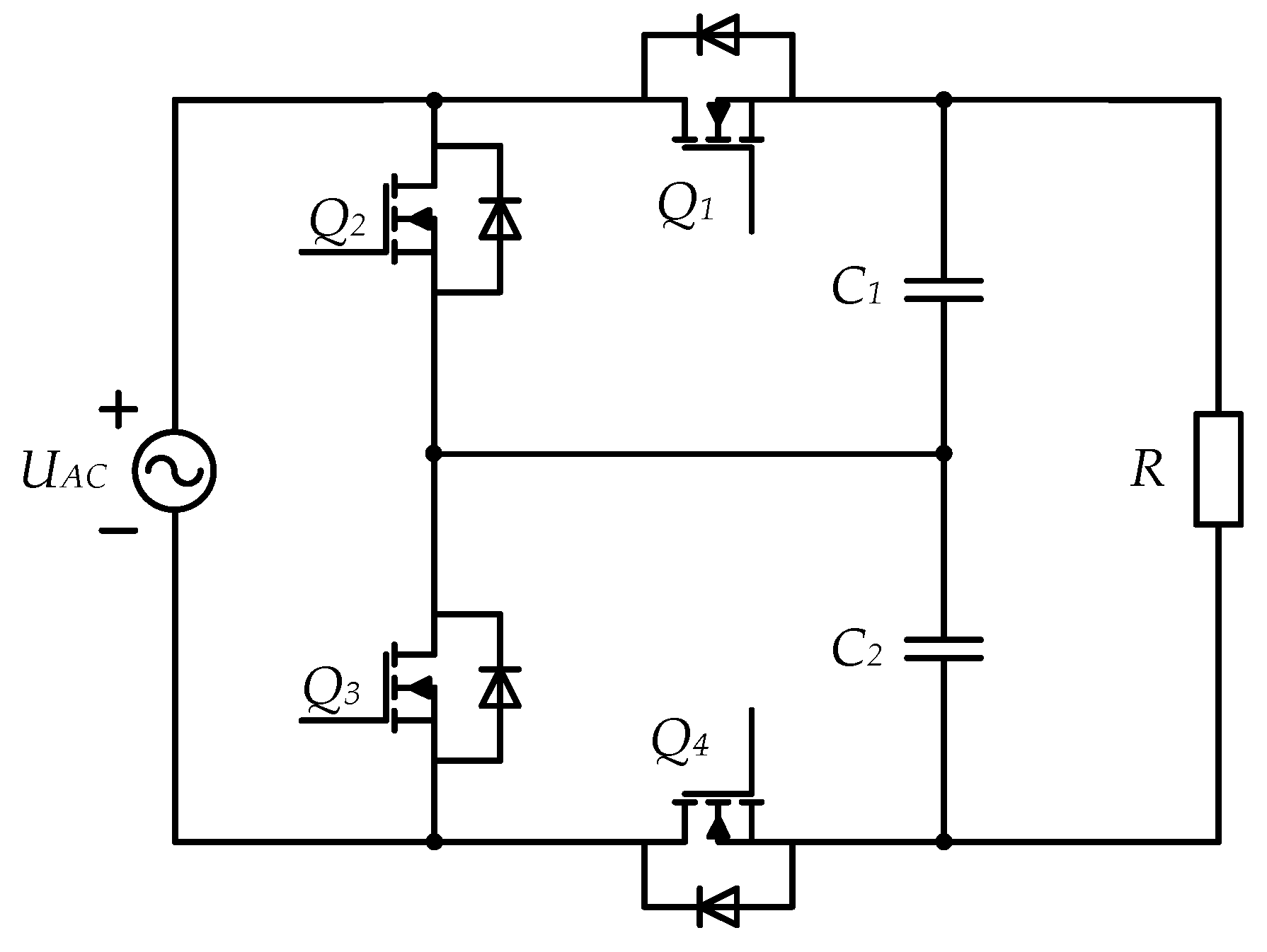
Colak et al. [78] proposed a novel multi-level bidirectional DC-DC converter, as shown in Figure 15, which achieves higher efficiency than traditional multi-level topologies by optimizing the phase-shift angle between switches. A 1 kW WPT system was designed and tested under different load conditions with coil spacing of eight inches (approximately 20.3 cm). The system showed an average efficiency improvement of 3% compared to traditional multi-level topologies and achieved the maximum efficiency of 93% at around 900 W power.
Figure 16 [55] shows a topology that integrates a full-bridge diode rectifier with a pair of interleaved buck converters and removes the overlapping components between the two. This design is achieved through an AC input current synchronous modulation scheme that combines PSM and PWM control to achieve efficient operation and precise output voltage regulation. By reducing the required number of power switches (especially diodes) while retaining the joint operation of rectification and voltage regulation, this topology simplifies the circuit design and reduces the hardware complexity and cost.
In addition, this topology can achieve a continuous DC output current and significantly reduce the current ripple (by 71%). This feature smooths the output current and reduces the dependence on the output capacitance, thereby improving the overall performance of the system. The design of interleaved buck converters improves the output current capabilities, making them particularly suitable for applications that require high charging currents. Experimental results show that the receiver achieves peak efficiency of up to 96% under a switching frequency of 100 kHz, output voltage of 12 V, and output power of 35 W.
Li et al. [54] employed a similar interleaved parallel buck circuit and introduced pseudo DC-link capacitors. These capacitors automatically balance the current between the output inductors through a charge balancing mechanism, without the need for additional current sensors or complex control strategies. Even in the case of mismatched inductance or capacitance parameters, this design can maintain the current balance, further enhancing the robustness and reliability of the system.
The topological performance of the single-stage structures applied to the WPT system receiver is compared in Table 3.
Currently, DWPT systems predominantly utilize two-stage receivers. Particularly in high-power applications, the stringent requirements regarding electrical parameters, such as the voltage rating of system switches, coupled with the relatively low cost of two-stage receivers that use fewer switches, make topologies employing uncontrolled rectifiers and DC-DC converters more prevalent. Moreover, when large-scale adjustments of the output voltage or higher input–output ratios are required, two-stage receivers often emerge as the optimal solution.
However, due to the complexity of two-stage receivers and the necessity to synchronize the resonant frequency of the WPT system with the switching frequency of the DC-DC converter, single-stage receivers are frequently preferred in low-power scenarios. Owing to their minimal component count, single-stage receivers can achieve a smaller footprint for the receiver, making them well suited for industries that demand high space utilization.

4. Critical Technique

To date, there have been many advances in receivers applied to WPT systems. The main focus is on the selection of the circuit topology and its related control methods [81]. There are two main core purposes: (1) to regulate the output voltage or current to meet the requirements of the load and (2) to maximize the efficiency of WPT systems. To achieve these goals, it is necessary to analyze and adjust the topology and key parameters of the receiver to maximize the efficiency.
The selection of output capacitors for voltage regulation in a two-stage receiver directly affects the stability of the WPT system. Specifically, when the output impedance of the current WPT system intersects with the input impedance of the DC-DC converter at a specific frequency and the phase difference exceeds 180°, the system will trigger instability. A capacitance that is too small will significantly increase the peak impedance of the front-end WPT system, reducing its resonant frequency and making it easier to intersect with the low-frequency input impedance of the buck. Although excessive capacitance can improve the stability, it can cause the starting current to exceed the limit of the component, posing a threat to hardware safety [25]. To avoid these problems, it is necessary to combine theoretical and experimental designs. First, the impedance characteristics are analyzed using the Middlebrook criterion to ensure that the amplitude and phase conditions are met at the impedance intersection frequency points and the phase difference is less than 180°. Second, the selection of the capacitors should consider upper and lower limit constraints: the minimum capacitor ensures the continuous operation mode of the receiving end, and the maximum capacitor limits the starting current. In practical design, a larger value should be selected to prioritize stability [82].
Although the linear control method based on the small-signal model can achieve the stable control of local operating points, its essence is the linear approximation of the nonlinear large-signal model under specific operating conditions, which can easily lead to control mismatches when the system’s operating range is extended [28]. Yang et al. [36] and Zhou et al. [83] proposed a nonlinear control strategy based on large-signal modeling, which has the advantage of being able to adapt to a wider working range. However, while these methods improve the system’s adaptability, they also introduce new challenges, such as the high complexity of control law design and large real-time computational load. Notably, existing nonlinear controllers generally suffer from the problem of fuzzy definitions of quantitative working intervals. This can be achieved through algorithm simplification and collaborative hardware optimization. First, the complex nonlinear equations are pre-computed offline as equivalent control signals to reduce the real-time solving requirements. Second, a discretization model and the dimensionality reduction of state variables are adopted to reduce the computational complexity, combined with hardware acceleration modules (such as DSP instructions) to improve the computational efficiency. Simultaneously, the control cycle and task priority are optimized to ensure real-time critical calculations, and repetitive and complex operations are replaced with table lookup or piecewise linear approximation.
The control of single-stage receivers is mainly achieved by collecting electrical parameter information from the receiver to adjust the switching modes of the internal switches. Owing to the different topology control methods, the control strategies also have relative uniqueness, with the main purpose of improving the system’s efficiency, stability, and dynamic response capabilities.
Adaptive Synchronous Driving Phase Control: Zhao et al. [62] proposed an ASDPC method for a full-bridge rectifier based on GaN for a WPT system at 6.78 MHz. By optimizing the driving phase and dead time, this method achieves critical ZVS operation over a wide load range, significantly improving the efficiency and stability of the system.
Pulse Density Modulation: Li et al. [59] proposed a maximum-efficiency point tracking control method based on PDM, where the receiver uses a half-bridge active rectifier. This method controls power transmission by adjusting the number of pulses, rather than the pulse width or frequency, thereby achieving soft switching and resonance tuning. The experimental results show that PDM can significantly improve the system’s efficiency, maintaining efficiency of over 70% even at very low coupling coefficients, while effectively regulating the output voltage and reducing the ripple.
Multi-Level Converters: Colak et al. [70] proposed a novel multi-level bidirectional DC-DC converter, which achieves higher efficiency than traditional multi-level topologies by optimizing the phase-shift angle between switches. The purpose is to reduce the voltage stress of the switches by 50% using a multi-level topology and to achieve zero-voltage switching by combining LC resonance at a fixed resonant frequency (150 kHz), effectively reducing switching losses. It innovatively uses the phase shift within the bridge arm to control the output voltage amplitude and the phase shift between the bridges to adjust the power transmission phase angle. When β − φ/2 = 90° is satisfied, the reactive power of the system is minimized. By dynamically adjusting the phase-shift angle, the system always operates in a near-resonant state. A 1 kW WPT system was designed and tested under different load conditions with coil spacing of eight inches (approximately 20.3 cm). The system showed an average efficiency improvement of 3% compared to traditional multi-level topologies and achieved the maximum efficiency of 93% at around 900 W power.

5. Future Trends and Prospects

5.1. Loss and Efficiency Optimization Under High-Frequency Operation

High-frequency operation can improve the power density and transmission efficiency of WPT systems, but it also brings higher switching losses. Especially for the receiver, high-frequency operation may cause the parasitic parameters of inductance and capacitance to affect the system’s performance. New high-frequency magnetic materials [84,85,86] and devices can be applied to the receiver components to reduce high-frequency losses and improve the performance of magnetic devices. Modulation strategies at high frequencies, such as PDM and PFM, can be used to optimize the system’s efficiency.

5.2. Expansion of Voltage Gain Range and Compatibility

Expanding the voltage gain range of the WPT system may cause compatibility issues due to the fixed operating voltage of existing equipment, standard protocol limitations, and increased electromagnetic interference. However, the seamless integration of different voltage levels can be achieved through adaptive resonant networks (such as variable capacitance/inductance components), multi-level power conversion architectures (such as wide-range DC-DC converters), and intelligent control algorithms (such as dynamic frequency adjustment and model predictive control). Modular design and standard protocol expansion can further reduce compatibility conflicts, ensuring flexible system expansion and compatibility with diverse device requirements.
To balance efficiency and stability, it is necessary to incorporate soft switching technology to reduce losses and suppress interference by optimizing the electromagnetic shielding and filtering design. The feasibility of such technology has been verified in practical application scenarios, such as supporting 400 V/800 V platforms for the wireless charging of electric vehicles and adapting multi-device charging pads to different power terminals. Future research should focus on broadband resonance technology, efficient converter topologies, and the standardization of cross-device communication protocols to achieve more efficient voltage gain expansion and global compatibility in complex scenarios.
The dynamic impedance adjustment capabilities of active rectifiers provide a new approach for wide-voltage-gain design. For example, by combining adaptive resonant networks with intelligent control algorithms [72], a 10:1 voltage regulation range can be achieved without the need for additional DC-DC cascading, while being compatible with multi-device charging protocols (such as Qi standard extensions).

5.3. System Stability and Dynamic Response Optimization

The rapid fluctuation of the input voltage in the DWPT system may lead to the instability of the system’s output current and voltage when the driving speed of the vehicle changes. In addition, system stability faces challenges under non-ideal coupling conditions. Analyzing the stability boundary of a DWPT system, identifying the parameters influencing the stability boundary, and establishing a mathematical model are worthwhile research directions. An additional question is how to optimize the control strategies to achieve a faster dynamic response and higher system stability. It is also necessary to explore control methods based on artificial intelligence to achieve adaptive system control.

5.4. Wireless Energy and Simultaneous Information Interpretation

Realizing information transmission while transmitting wireless energy is an important development direction for future WPT systems. The core challenges faced by this technology include crosstalk between power and data signals, reduced signal-to-noise ratios (SNRs) in high-power scenarios, the impact of modulation on system efficiency, and insufficient misalignment tolerance. The universal solution covers physical isolation (such as orthogonal coil design), frequency band separation (low-frequency power and high-frequency data), and efficient modulation techniques. In the future, further exploration is needed regarding switch noise suppression, multi-node communication protocols, and new isolation methods to expand their real-time control and high-reliability applications in fields such as electric vehicle charging and medical implantation. Whether the receiver topology can provide new directions and methods for modulation and the encoding of information is worth discussing.

6. Conclusions

This article systematically reviews the research progress regarding the topology of the receiver side in WPT systems. The design ideas, performance characteristics, and challenges faced by two-stage and single-stage receivers were analyzed in detail. The two-stage receiver, which relies on the combination of a rectifier and DC-DC converter, demonstrates the advantages of wide voltage regulation and high-precision outputs in high-power scenarios. Through improved solutions, such as a dual-switch buck–boost converter and impedance-shaping control, the system efficiency was increased to over 95%. However, the bottleneck of component redundancy and light-load efficiency still needs to be overcome. Single-stage receivers are known for their simplified structures, utilizing GaN devices and ASDPC technology, and have significant advantages in low-power and high-frequency scenarios. However, further solutions are required to address harmonic suppression and dynamic load adaptability issues. Under the premise of topology determination, improvements in control methods are key to further enhancing the system parameters. Finally, the future trends and prospects of receivers applied to WPT systems were analyzed.

Author Contributions

Conceptualization, L.K. and J.Z.; methodology, L.K.; software, J.Z.; validation, L.K.; formal analysis, Z.W.; investigation, L.K.; resources, Y.W.; data curation, Y.L.; writing—original draft preparation, L.K.; writing—review and editing, L.K. and J.Z.; visualization, J.Z.; supervision, X.G. and C.Z.; project administration, Y.L.; funding acquisition, J.Z. All authors have read and agreed to the published version of the manuscript.

Funding

This work was supported in part by the National Natural Science Foundation of China under Project 52107002; the Heilongjiang Natural Science Foundation’s Jointly Guided Project LH2024E045; the Postdoctoral Fellowship Program of CPSF, GZC20233438; and the Heilongjiang Postdoctoral Fund to pursue scientific research, LBH-Z20157.

Data Availability Statement

The data supporting the findings of this study are available by reasonable request to cathy-ying.liu@connect.polyu.hk.

Conflicts of Interest

All co-authors have seen and agree with the contents of the manuscript, and there are no financial interests to report. We certify that the submission is original work and is not under review for any other publication.

References

  1. Wang, D.; Zhang, J.; Cui, S.; Bie, Z.; Song, K.; Zhu, C.; Matveevich, M.I. Modern Advances in Magnetic Materials of Wireless Power Transfer Systems: A Review and New Perspectives. Nanomaterials 2022, 12, 3662. [Google Scholar] [CrossRef] [PubMed]
  2. Eikani, A.; Amirkhani, M.; Farmahini Farahani, E.; Pickert, V.; Mirsalim, M.; Vaez-Zadeh, S. Robust Wireless Power Transfer for EVs by Self-Oscillating Controlled Inverters and Identical Single-Coil Transmitting and Receiving Pads. Energies 2025, 18, 211. [Google Scholar] [CrossRef]
  3. Zhang, Y.; Wu, Y.; Shen, Z.; Pan, W.; Wang, H.; Dong, J.; Mao, X.; Liu, X. Integration of Onboard Charger and Wireless Charging System for Electric Vehicles with Shared Coupler, Compensation, and Rectifier. IEEE Trans. Ind. Electron. 2023, 70, 7511–7514. [Google Scholar] [CrossRef]
  4. Wu, L.; Zhang, B.; Jiang, Y. Position-Independent Constant Current or Constant Voltage Wireless Electric Vehicles Charging System Without Dual-Side Communication and DC–DC Converter. IEEE Trans. Ind. Electron. 2022, 69, 7930–7939. [Google Scholar] [CrossRef]
  5. Yang, L.; Wang, Y.; Guo, P.; Dong, K.; Cai, C. A Reconfigurable Rectifier Based Communication-Free Wireless LED Driver with Dual-Customization CC Outputs. IEEE Trans. Power Electron. 2025, 40, 2680–2684. [Google Scholar] [CrossRef]
  6. Wen, H.; Li, J.; Zhang, K.; Wang, P.; Yang, J.; Zhou, X.; Yang, L.; Tong, X.; Song, B. A Switchable Dual-Frequency LCC-S-S Compensated Three-Coil WPT System for Mobile Desktop Charging with Constant Current and Constant Voltage Outputs. IEEE Trans. Power Electron. 2025, 40, 7586–7598. [Google Scholar] [CrossRef]
  7. Pahlavan, S.; Shooshtari, M.; Jafarabadi Ashtiani, S. Star-Shaped Coils in the Transmitter Array for Receiver Rotation Tolerance in Free-Moving Wireless Power Transfer Applications. Energies 2022, 15, 8643. [Google Scholar] [CrossRef]
  8. Yang, X.; Gao, P.; Zhang, H.; Zhao, J.; Wang, T.; Xu, G. Temporal Interference Wireless Power Transfer Strategy with Passive Flexible Electrode for Vagus Nerve Stimulation. IEEE Trans. Antennas Propag. 2024, 72, 6908–6918. [Google Scholar] [CrossRef]
  9. Da, C.; Li, F.; Wang, L.; Tao, C.; Li, S.; Nie, M. Analysis and Implementation of Underwater Single Capacitive Coupled Simultaneous Wireless Power and Bidirectional Data Transfer System. IEEE Trans. Ind. Electron. 2024, 71, 15674–15684. [Google Scholar] [CrossRef]
  10. Liu, Y.; Li, B.; Pan, L.; Yao, S.; Dong, Z.; Zhang, J.; Zhu, C.; Cui, S. Review on Development and Research of Underwater Capacitive Power Transfer. Energies 2024, 17, 6496. [Google Scholar] [CrossRef]
  11. Zeng, Y.; Lu, C.; Liu, R.; He, X.; Rong, C.; Liu, M. Wireless Power and Data Transfer System Using Multidirectional Magnetic Coupler for Swarm AUVs. IEEE Trans. Power Electron. 2023, 38, 1440–1444. [Google Scholar] [CrossRef]
  12. Huang, W.; Zhang, Y.; Gao, F.; Yang, Y. Magnetic Structure Design of Wireless Power Transfer for Free-Rotating UAV with Low Stray Magnetic Fields. IEEE Trans. Ind. Electron. 2025, 72, 481–491. [Google Scholar] [CrossRef]
  13. Carpita, M.; De Vivo, M.; Gavin, S.; Bommottet, D. A Rotating Contactless Power Transfer System for Space Applications. In Proceedings of the 2014 International Symposium on Power Electronics, Electrical Drives, Automation and Motion, Ischia, Italy, 18–20 June 2014; pp. 238–242. [Google Scholar]
  14. Honda, S.; Shimada, S.; Tanaka, K.; Nakamura, K.; Imura, T.; Hata, K.; Hori, Y. Proposal and Evaluation of High-Heat Insulation System for Spacecraft by Using WPT. In Proceedings of the 2022 International Power Electronics Conference (IPEC-Himeji 2022-ECCE Asia), Himeji, Japan, 15–19 May 2022; pp. 775–782. [Google Scholar]
  15. Huang, M.; Lu, Y.; Martins, R.P. A Reconfigurable Bidirectional Wireless Power Transceiver for Battery-to-Battery Wireless Charging. IEEE Trans. Power Electron. 2019, 34, 7745–7753. [Google Scholar] [CrossRef]
  16. Onar, O.C.; Su, G.-J.; Asa, E.; Pries, J.; Galigekere, V.; Seiber, L.; White, C.; Wiles, R.; Wilkins, J. 20-kW Bi-Directional Wireless Power Transfer System with Energy Storage System Connectivity. In Proceedings of the 2020 IEEE Applied Power Electronics Conference and Exposition (APEC), New Orleans, LA, USA, 15–19 March 2020; pp. 3208–3214. [Google Scholar]
  17. Beh, T.C.; Imura, T.; Kato, M.; Hori, Y. Basic Study of Improving Efficiency of Wireless Power Transfer via Magnetic Resonance Coupling Based on Impedance Matching. In Proceedings of the 2010 IEEE International Symposium on Industrial Electronics, Bari, Italy, 4–7 July 2010; pp. 2011–2016. [Google Scholar]
  18. Sinha, S.; Kumar, A.; Regensburger, B.; Afridi, K.K. Design of High-Efficiency Matching Networks for Capacitive Wireless Power Transfer Systems. IEEE J. Emerg. Sel. Top. Power Electron. 2022, 10, 104–127. [Google Scholar] [CrossRef]
  19. Dong, M.; Wu, Z.; Song, D.; Yang, J.; Li, M.; Li, L. Enhancing Efficiency in Multireceiver Wireless Charging with Voltage Constraints Using Two-Stage Optimization Algorithm. IEEE Trans. Power Electron. 2024, 39, 14054–14064. [Google Scholar] [CrossRef]
  20. Zhang, X.; Zhang, X.; Yao, Y.; Yang, H.; Wang, Y.; Xu, D. High-Efficiency Magnetic Coupling Resonant Wireless Power Transfer System with Class-e Amplifier and Class-e Rectifier. In Proceedings of the 2017 IEEE Transportation Electrification Conference and Expo, Asia-Pacific (ITEC Asia-Pacific), Harbin, China, 7–10 August 2017; pp. 1–5. [Google Scholar]
  21. Huang, X.; Yu, Z.; Dou, Y.; Lin, S.; Ouyang, Z.; Andersen, M.A.E. Load-Independent Push–Pull Class E2 Topology With Coupled Inductors for MHz-WPT Applications. IEEE Trans. Power Electron. 2022, 37, 8726–8737. [Google Scholar] [CrossRef]
  22. Ramadoss, V.; Chandrasekar, B.; Ahmed, M.M.R.; Savio, A.D.; Rajamanickam, N.; Alghamdi, T.A.H. Research Insights on Recent Power Converter Topologies and Control Strategies for Wireless EV Chargers: A Comprehensive Study. IEEE Open J. Power Electron. 2024, 5, 1641–1658. [Google Scholar] [CrossRef]
  23. Hannan, M.A.; Lipu, M.S.H.; Ker, P.J.; Begum, R.A.; Agelidis, V.G.; Blaabjerg, F. Power Electronics Contribution to Renewable Energy Conversion Addressing Emission Reduction: Applications, Issues, and Recommendations. Appl. Energy 2019, 251, 113404. [Google Scholar] [CrossRef]
  24. Do, H.-L. Zero-Voltage-Switching Synchronous Buck Converter with a Coupled Inductor. IEEE Trans. Ind. Electron. 2011, 58, 3440–3447. [Google Scholar] [CrossRef]
  25. Song, S.; Zhang, X.; Li, H.; Zhang, Q. Reconsidering Regulator Capacitor Selection for Wireless Charging System with a Receiver-Side Buck. In Proceedings of the 2020 IEEE 9th International Power Electronics and Motion Control Conference (IPEMC2020-ECCE Asia), Nanjing, China, 29 November–2 December 2020; pp. 1104–1108. [Google Scholar]
  26. Zhang, X.; Ruan, X.; Zhong, Q.-C. Improving the Stability of Cascaded DC/DC Converter Systems via Shaping the Input Impedance of the Load Converter with a Parallel or Series Virtual Impedance. IEEE Trans. Ind. Electron. 2015, 62, 7499–7512. [Google Scholar] [CrossRef]
  27. Tan, T.; Chen, K.; Lin, Q.; Jiang, Y.; Yuan, L.; Zhao, Z. Impedance Shaping Control Strategy for Wireless Power Transfer System Based on Dynamic Small-Signal Analysis. IEEE Trans. Circuits Syst. Regul. Pap. 2021, 68, 1354–1365. [Google Scholar] [CrossRef]
  28. Li, Z.; Zhu, C.; Jiang, J.; Song, K.; Wei, G. A 3-kW Wireless Power Transfer System for Sightseeing Car Supercapacitor Charge. IEEE Trans. Power Electron. 2017, 32, 3301–3316. [Google Scholar] [CrossRef]
  29. Yuan, H.; Li, K.; Li, S.; Tan, S.C.; Hui, S.Y.R. On the Control of DC-DC Converters in the SS-Compensated Wireless Power Transfer System. In Proceedings of the 2024 IEEE Wireless Power Technology Conference and Expo (WPTCE), Kyoto, Japan, 8–11 May 2024; pp. 788–792. [Google Scholar] [CrossRef]
  30. Li, K.; Yuan, H.; Tan, S.-C.; Hui, S.Y.R. Overshoot Damping and Dynamics Improvement in Wireless Power Transfer Systems via Receiver-Side Controller Design. IEEE Trans. Power Electron. 2022, 37, 2362–2371. [Google Scholar] [CrossRef]
  31. Dong, S.; Zhang, B.; Gao, X.; Li, H.; Zhu, C. The Impact of Rectifier Filter Capacitance on Buck Converter Output Voltage in Wireless Power Receiver System with Input Current Source. IEEE Trans. Power Electron. 2024, 39, 8947–8958. [Google Scholar] [CrossRef]
  32. Song, S.; Zhang, Q.; He, Z.; Li, H.; Zhang, X. Uniform Power Dynamic Wireless Charging System with I-Type Power Supply Rail and DQ-Phase-Receiver Employing Receiver-Side Control. IEEE Trans. Power Electron. 2020, 35, 11205–11212. [Google Scholar] [CrossRef]
  33. Song, S.; Dong, S.; Zhang, Q. Receiver Current-Stress Mitigation for a Dynamic Wireless Charging System Employing Constant Resistance Control. IEEE Trans. Power Electron. 2021, 36, 3883–3893. [Google Scholar] [CrossRef]
  34. Fu, M. A Cascaded Boost–Buck Converter for High-Efficiency Wireless Power Transfer Systems. IEEE Trans. Ind. Inform. 2014, 10, 1972–1980. [Google Scholar] [CrossRef]
  35. Gheisarnejad, M.; Farsizadeh, H.; Tavana, M.-R.; Khooban, M.H. A Novel Deep Learning Controller for DC–DC Buck–Boost Converters in Wireless Power Transfer Feeding CPLs. IEEE Trans. Ind. Electron. 2021, 68, 6379–6384. [Google Scholar] [CrossRef]
  36. Yang, Y.; Zhong, W.; Kiratipongvoot, S.; Tan, S.-C.; Hui, S.Y.R. Dynamic Improvement of Series–Series Compensated Wireless Power Transfer Systems Using Discrete Sliding Mode Control. IEEE Trans. Power Electron. 2018, 33, 6351–6360. [Google Scholar] [CrossRef]
  37. Hu, X.; Wang, Y.; Jiang, Y.; Lei, W.; Dong, X. Maximum Efficiency Tracking for Dynamic Wireless Power Transfer System Using LCC Compensation Topology. In Proceedings of the 2018 IEEE Energy Conversion Congress and Exposition (ECCE), Portland, OR, USA, 23–27 September 2018; pp. 1992–1996. [Google Scholar]
  38. Zhang, Q.; Zhang, X.; Li, W.; Hu, T.; Wang, Y.; Shen, S. New Control Method for Receiver-Side DC–DC Converter with Large Stability Margin and Fluctuation Suppression Toward DWPT System. IEEE Trans. Ind. Electron. 2023, 70, 7944–7954. [Google Scholar] [CrossRef]
  39. Yuan, C.; Su, S. Dual-Edge Modulated Dual-Switch Buck-Boost Converter. Appl. Electron. Tech. 2018, 44, 124–128. [Google Scholar] [CrossRef]
  40. Li, K.; Tan, S.-C.; Hui, R.S.Y. On Beat Frequency Oscillation of Two-Stage Wireless Power Receivers. IEEE Trans. Power Electron. 2020, 35, 12741–12751. [Google Scholar] [CrossRef]
  41. Pal, S.; Ki, W.-H. 40.68 MHz Digital On-Off Delay-Compensated Active Rectifier for WPT of Biomedical Applications. IEEE Trans. Circuits Syst. II Express Briefs 2020, 67, 3307–3311. [Google Scholar] [CrossRef]
  42. Zheng, K.S.; Liu, X.; Wang, X.; Su, Q.; Liu, Y. A 6.78 MHz CMOS Active Rectifier with Hybrid Mode Delay Compensation for Wireless Power Transfer Systems. IEEE Access 2022, 10, 46176–46186. [Google Scholar] [CrossRef]
  43. Lu, Y.; Ki, W.-H. A 13.56 MHz CMOS Active Rectifier With Switched-Offset and Compensated Biasing for Biomedical Wireless Power Transfer Systems. IEEE Trans. Biomed. Circuits Syst. 2014, 8, 334–344. [Google Scholar] [CrossRef]
  44. Cheng, H.-C.; Gong, C.-S.A.; Kao, S.-K. A 13.56 MHz CMOS High-Efficiency Active Rectifier with Dynamically Controllable Comparator for Biomedical Wireless Power Transfer Systems. IEEE Access 2018, 6, 49979–49989. [Google Scholar] [CrossRef]
  45. Xue, Z.; Fan, S.; Li, D.; Zhang, L.; Gou, W.; Geng, L. A 13.56 MHz, 94.1% Peak Efficiency CMOS Active Rectifier with Adaptive Delay Time Control for Wireless Power Transmission Systems. IEEE J. Solid-State Circuits 2019, 54, 1744–1754. [Google Scholar] [CrossRef]
  46. Ma, Y.; Cui, K.; Ye, Z.; Sun, Y.; Fan, X. A 13.56-MHz Active Rectifier with SAR-Assisted Coarse-Fine Adaptive Digital Delay Compensation for Biomedical Implantable Devices. IEEE Solid-State Circuits Lett. 2020, 3, 122–125. [Google Scholar] [CrossRef]
  47. Park, H.-G.; Jang, J.-H.; Kim, H.-J.; Park, Y.-J.; Oh, S.; Pu, Y.; Hwang, K.C.; Yang, Y.; Lee, K.-Y. A Design of a Wireless Power Receiving Unit with a High-Efficiency 6.78-MHz Active Rectifier Using Shared DLLs for Magnetic-Resonant A4 WP Applications. IEEE Trans. Power Electron. 2016, 31, 4484–4498. [Google Scholar] [CrossRef]
  48. Cheng, L.; Ki, W.-H.; Lu, Y.; Yim, T.-S. Adaptive On/Off Delay-Compensated Active Rectifiers for Wireless Power Transfer Systems. IEEE J. Solid-State Circuits 2016, 51, 712–723. [Google Scholar] [CrossRef]
  49. Li, X.; Tsui, C.-Y.; Ki, W.-H. A 13.56 MHz Wireless Power Transfer System With Reconfigurable Resonant Regulating Rectifier and Wireless Power Control for Implantable Medical Devices. IEEE J. Solid-State Circuits 2015, 50, 978–989. [Google Scholar] [CrossRef]
  50. Cheng, L.; Ki, W.-H.; Tsui, C.-Y. A 6.78-MHz Single-Stage Wireless Power Receiver Using a 3-Mode Reconfigurable Resonant Regulating Rectifier. IEEE J. Solid-State Circuits 2017, 52, 1412–1423. [Google Scholar] [CrossRef]
  51. Li, K.; Tan, S.-C.; Hui, R.S.Y. Low-Cost Single-Switch Bidirectional Wireless Power Transceiver for Peer-to-Peer Charging. IEEE J. Emerg. Sel. Top. Power Electron. 2021, 9, 3781–3790. [Google Scholar] [CrossRef]
  52. Li, K.; Tan, S.-C.; Hui, R.S.Y. Single-Switch-Regulated Resonant WPT Receiver. IEEE Trans. Power Electron. 2019, 34, 10386–10391. [Google Scholar] [CrossRef]
  53. Mao, F.; Lu, Y.; Seng-Pan, U.; Martins, R.P. A Reconfigurable Cross-Connected Wireless-Power Transceiver for Bidirectional Device-to-Device Charging with 78.1% Total Efficiency. In Proceedings of the 2018 IEEE International Solid—State Circuits Conference—(ISSCC), San Francisco, CA, USA, 11–15 February 2018; pp. 140–142. [Google Scholar]
  54. Li, K.; Tan, S.-C.; Hui, S.Y.R. Interleaved Buck-Type Rectifier With Pseudo-DC-Link Capacitors for Automatic Current Balancing. IEEE Trans. Ind. Electron. 2022, 69, 12676–12687. [Google Scholar] [CrossRef]
  55. Li, K.; Tan, S.-C.; Hui, S.Y.R. Efficient Hybrid-Modulated Single-Stage Wireless Power Receiver with Continuous DC Current. IEEE Trans. Power Electron. 2021, 36, 13504–13514. [Google Scholar] [CrossRef]
  56. Liu, Y.; Li, B.; Huang, M.; Chen, Z.; Zhang, X. An Overview of Regulation Topologies in Resonant Wireless Power Transfer Systems for Consumer Electronics or Bio-Implants. Energies 2018, 11, 1737. [Google Scholar] [CrossRef]
  57. Lu, Y.; Huang, M.; Cheng, L.; Ki, W.-H.; U, S.-P.; Martins, R.P. A Dual-Output Wireless Power Transfer System with Active Rectifier and Three-Level Operation. IEEE Trans. Power Electron. 2017, 32, 927–930. [Google Scholar] [CrossRef]
  58. Yang, F.-B.; Fuh, J.; Li, Y.-H.; Takamiya, M.; Chen, P.-H. Structure-Reconfigurable Power Amplifier (SR-PA) and 0X/1X Regulating Rectifier for Adaptive Power Control in Wireless Power Transfer System. IEEE J. Solid-State Circuits 2021, 56, 2054–2064. [Google Scholar] [CrossRef]
  59. Namgoong, G.; Park, W.; Bien, F. A 13.56 MHz Wireless Power Transfer System With Fully Integrated PLL-Based Frequency-Regulated Reconfigurable Duty Control for Implantable Medical Devices. IEEE Trans. Biomed. Circuits Syst. 2022, 16, 1116–1128. [Google Scholar] [CrossRef]
  60. Colak, K.; Asa, E.; Bojarski, M.; Czarkowski, D.; Onar, O.C. A Novel Phase-Shift Control of Semibridgeless Active Rectifier for Wireless Power Transfer. IEEE Trans. Power Electron. 2015, 30, 6288–6297. [Google Scholar] [CrossRef]
  61. Berger, A.; Agostinelli, M.; Vesti, S.; Oliver, J.A.; Cobos, J.A.; Huemer, M. A Wireless Charging System Applying Phase-Shift and Amplitude Control to Maximize Efficiency and Extractable Power. IEEE Trans. Power Electron. 2015, 30, 6338–6348. [Google Scholar] [CrossRef]
  62. Bai, X.; Lu, Y.; Zhan, C.; Martins, R.P. A 6.78-MHz Wireless Power Transfer System with Inherent Wireless Phase Shift Control Without Feedback Data Sensing Coil. IEEE J. Solid-State Circuits 2023, 58, 1746–1757. [Google Scholar] [CrossRef]
  63. Huang, C.; Kawajiri, T.; Ishikuro, H. A 13.56-MHz Wireless Power Transfer System with Enhanced Load-Transient Response and Efficiency by Fully Integrated Wireless Constant-Idle-Time Control for Biomedical Implants. IEEE J. Solid-State Circuits 2018, 53, 538–551. [Google Scholar] [CrossRef]
  64. Sadeghi Gougheri, H.; Kiani, M. Self-Regulated Reconfigurable Voltage/Current-Mode Inductive Power Management. IEEE J. Solid-State Circuits 2017, 52, 3056–3070. [Google Scholar] [CrossRef]
  65. Kim, C.; Ha, S.; Park, J.; Akinin, A.; Mercier, P.P.; Cauwenberghs, G. A 144-MHz Fully Integrated Resonant Regulating Rectifier with Hybrid Pulse Modulation for Mm-Sized Implants. IEEE J. Solid-State Circuits 2017, 52, 3043–3055. [Google Scholar] [CrossRef]
  66. Erfani, R.; Marefat, F.; Mohseni, P. A Dual-Output Single-Stage Regulating Rectifier with PWM and Dual-Mode PFM Control for Wireless Powering of Biomedical Implants. IEEE Trans. Biomed. Circuits Syst. 2020, 14, 1195–1206. [Google Scholar] [CrossRef]
  67. Lu, T.; Du, S. A Single-Stage Regulating Voltage-Doubling Rectifier for Wireless Power Transfer. IEEE Solid-State Circuits Lett. 2023, 6, 29–32. [Google Scholar] [CrossRef]
  68. Lin, J.; Zhan, C.; Lu, Y. A 6.78-MHz Single-Stage Wireless Power Receiver with Ultrafast Transient Response Using Hysteretic Control and Multilevel Current-Wave Modulation. IEEE Trans. Power Electron. 2021, 36, 9918–9926. [Google Scholar] [CrossRef]
  69. Serban, E.; Pondiche, C.; Ordonez, M. Analysis and Design of Bidirectional Parallel-Series DAB-Based Converter. IEEE Trans. Power Electron. 2023, 38, 10370–10382. [Google Scholar] [CrossRef]
  70. Li, M.; Deng, J.; Chen, D.; Wang, W.; Wang, Z. Maximum Efficiency Tracking and ZVS Realization for Wide Output Voltage Range Employing Segmented TPS Modulation Scheme. IEEE Trans. Veh. Technol. 2023, 72, 12770–12783. [Google Scholar] [CrossRef]
  71. Li, Y.; Sun, W.; Zhu, X.; Hu, J. A Hybrid Modulation Control for Wireless Power Transfer Systems to Improve Efficiency Under Light-Load Conditions. IEEE Trans. Ind. Electron. 2022, 69, 6870–6880. [Google Scholar] [CrossRef]
  72. Zhao, C.; Xiao, G.; Wu, M.; Zhu, L.; Cui, H.; Wang, L.; Yan, Z. An Adaptive Synchronous Driving Phase Control Method of GaN-Based Full-Bridge 6.78-MHz WPTS. IEEE Trans. Power Electron. 2024, 39, 3787–3796. [Google Scholar] [CrossRef]
  73. Li, H.; Fang, J.; Wang, K. Pulse Density Modulation for Maximum Efficiency Point Tracking of Wireless Power Transfer Systems. IEEE Trans. Power Electron. 2018, 33, 5492–5501. [Google Scholar] [CrossRef]
  74. Namgoong, G.; Choi, E.; Park, W.; Lee, B.; Park, H.; Ma, H.; Bien, F. 3–12-V Wide Input Range Adaptive Delay Compensated Active Rectifier for 6.78-MHz Loosely Coupled Wireless Power Transfer System. IEEE Trans. Circuits Syst. Regul. Pap. 2021, 68, 2702–2713. [Google Scholar] [CrossRef]
  75. Diekhans, T.; De Doncker, R.W. A Dual-Side Controlled Inductive Power Transfer System Optimized for Large Coupling Factor Variations and Partial Load. IEEE Trans. Power Electron. 2015, 30, 6320–6328. [Google Scholar] [CrossRef]
  76. Wu, M.; Yang, X.; Chen, W.; Wang, L.; Jiang, Y.; Zhao, C.; Yan, Z. A Dual-Sided Control Strategy Based on Mode Switching for Efficiency Optimization in Wireless Power Transfer System. IEEE Trans. Power Electron. 2021, 36, 8835–8848. [Google Scholar] [CrossRef]
  77. Liu, X.; Gao, F.; Wang, T.; Khan, M.M.; Zhang, Y.; Xia, Y.; Wheeler, P. A Multi-Inverter Multi-Rectifier Wireless Power Transfer System for Charging Stations with Power Loss Optimized Control. IEEE Trans. Power Electron. 2023, 38, 9261–9277. [Google Scholar] [CrossRef]
  78. Colak, K.; Asa, E.; Czarkowski, D.; Komurcugil, H. A Novel Multi-Level Bi-Directional DC/DC Converter for Inductive Power Transfer Applications. In Proceedings of the Iecon 2015—41st Annual Conference of the IEEE Industrial Electronics Society, Yokohama, Japan, 9–12 November 2015; pp. 3827–3831. [Google Scholar]
  79. Cheng, L.; Ge, X.; Ng, W.C.; Ki, W.-H.; Zheng, J.; Kwok, T.F.; Tsui, C.-Y.; Liu, M. A 6.78-MHz Single-Stage Wireless Charger with Constant-Current Constant-Voltage Charging Technique. IEEE J. Solid-State Circuits 2020, 55, 999–1010. [Google Scholar] [CrossRef]
  80. Choi, J.-H.; Yeo, S.-K.; Park, S.; Lee, J.-S.; Cho, G.-H. Resonant Regulating Rectifiers (3R) Operating for 6.78 MHz Resonant Wireless Power Transfer (RWPT). IEEE J. Solid-State Circuits 2013, 48, 2989–3001. [Google Scholar] [CrossRef]
  81. Pan, J.; Abidi, A.A.; Jiang, W.; Markovic, D. Simultaneous Transmission of Up To 94-mW Self-Regulated Wireless Power and Up To 5-Mb/s Reverse Data Over a Single Pair of Coils. IEEE J. Solid-State Circuits 2019, 54, 1003–1016. [Google Scholar] [CrossRef]
  82. Chen, C.-I.; Covic, G.A.; Boys, J.T. Regulator Capacitor Selection for Series Compensated IPT Pickups. In Proceedings of the 2008 34th Annual Conference of IEEE Industrial Electronics, Orlando, FL, USA, 10–13 November 2008; pp. 932–937. [Google Scholar]
  83. Zhou, Z.; Zhang, L.; Liu, Z.; Chen, Q.; Long, R.; Su, H. Model Predictive Control for the Receiving-Side DC–DC Converter of Dynamic Wireless Power Transfer. IEEE Trans. Power Electron. 2020, 35, 8985–8997. [Google Scholar] [CrossRef]
  84. Zheng, Z.; Fang, X.; Zheng, Y.; Feng, H. A Wireless Power Transfer System Based on Dual-Band Metamaterials. IEEE Microw. Wirel. Compon. Lett. 2022, 32, 615–618. [Google Scholar] [CrossRef]
  85. Correa, D.C.; Resende, U.C.; Bicalho, F.S. Experiments With a Compact Wireless Power Transfer System Using Strongly Coupled Magnetic Resonance and Metamaterials. IEEE Trans. Magn. 2019, 55, 8401904. [Google Scholar] [CrossRef]
  86. Lee, W.; Yoon, Y.-K. Tunable Metamaterial Slab for Efficiency Improvement in Misaligned Wireless Power Transfer. IEEE Microw. Wirel. Compon. Lett. 2020, 30, 912–915. [Google Scholar] [CrossRef]
Figure 1. Structure of WPT system [15,16,17].
Energies 18 01493 g001
Figure 2. Classification of existing WPT receivers.
Energies 18 01493 g002
Figure 3. Two-stage receiver topology of the WPT system.
Energies 18 01493 g003
Figure 4. Common non-isolated DC-DC converters. (a) Buck. (b) Boost. (c) Buck–boost. (d) Cuk. (e) Zeta. (f) SEPIC. (g) Dual-switch buck–boost [23].
Energies 18 01493 g004
Figure 5. Synchronous buck converter topology in WPT receiver.
Energies 18 01493 g005
Figure 6. Dual-input buck converter topology in WPT receiver [32].
Energies 18 01493 g006
Figure 7. Boost converter topology in WPT receiver.
Energies 18 01493 g007
Figure 8. Cascade boost–buck converter topology in WPT receiver [34].
Energies 18 01493 g008
Figure 9. Single buck–boost converter topology in WPT receiver.
Energies 18 01493 g009
Figure 10. Dual-switch buck–boost converter topology in WPT receiver [38].
Energies 18 01493 g010
Figure 11. Three-level single-inductor dual-output converter. (a) Full-bridge rectifier (1× mode). (b) Half-bridge rectifier (½× mode). (c) Free-wheeling mode (0× mode) [56].
Energies 18 01493 g011
Figure 12. Full-bridge active rectifier in WPT system.
Energies 18 01493 g012
Figure 13. Half-bridge active rectifier in WPT system.
Energies 18 01493 g013
Figure 14. Dual-switch active converter in WPT system receiver.
Energies 18 01493 g014
Figure 15. Multi-level converter in WPT system [78].
Energies 18 01493 g015
Figure 16. Full-bridge diode rectifier interleaved buck hybrid converter [55].
Energies 18 01493 g016
Table 1. Performance comparison of DC-DC converters [23].
TopologyNumber of SwitchesNumber of LCOutput PolarityIinEfficiency
Buck11/1SameDiscontinuousHigh
Boost11/1SameContinuousHigh
Single buck–boost11/1OppositeDiscontinuousMedium
Cuk22/2OppositeContinuousMedium
Zeta22/2SameDiscontinuousMedium
SEPIC22/2SameContinuousMedium
Dual-switch buck–boost21/1SameDiscontinuousHigh
Table 2. Performance comparison of typical two-stage converters in WPT system receiver.
Converter TypeAuthorFrequency of RegulatorOutput RatingControllerAdvantagesDisadvantagesFeatures
BuckZhang et al. [27]20 kHz80 V,
1600 W
PI controllerSimple structure,
high output current capabilities
Hard switchingEfficiency 92.5%
Li et al. [28]20 kHz91.4 V, 3.3 kWPI controllerEfficiency 88.05%
Synchronous BuckLi et al. [30]200 kHz5 V,
5 W
Feedforward controlHigh efficiency,
fast dynamic response
High control accuracy requirementsSettling time shortened by 65.1%,
overshoot reduced by 13.2%
Dual-Input BuckSong et al. [32]20 kHz133 V, 1.5 kWConstant resistance (double closed loop)High efficiency,
low power fluctuation
Performance degradation under non-ideal conditionsFluctuation factors 1.37%, 3.19%, and 4.69%
BoostSong et al. [33]20 kHz210 V, 1470 WConstant-resistance controlInput current continuous,
low current stress
Control complexityReceiver-side current stress, 29% stress reduction
Cascade Boost–BuckFu et al. [34]20 kHz17 V,
40 W
Double PI controllerNo additional impedance matching networkComplex structure,
low power level
Efficiency 81%
Single Buck–BoostYang et al. [36]20 kHz10 V,
40 W
Discrete sliding mode controlWide range input and output voltage,
simple structure
Opposite polarity,
high switch stress
Efficiency 60%
Hu et al. [37]100 kHz45 V,
200 W
Dynamic mutual inductance estimationEfficiency 80%
Dual Buck–BoostZhang et al. [38]20 kHz60 V,
360 W
Asynchronous controlWide voltage conversion range,
low switch stress
Complex control strategyEfficiency 95.57%
Table 3. Comparison of the performance of typical single-stage converters in WPT system receivers.
Converter TypeAuthorsFrequency of RegulatorOutput RatingControllerAdvantagesDisadvantagesFeatures
Three-mode reconfigurable rectifierCheng et al. [79]56.65 kHz3.6 V,
3.5 W
PWM with mode switchingFlexible output voltage control,
multiple application scenarios
Complex control, complex hardware, and low efficiencyEfficiency 92.2%
(Receiver)
Choi et al. [80]6.78 MHz5 V,
6 W
Manual controlEfficiency 86%
(Receiver)
Full-bridge active rectifierZhao et al. [72]6.78 MHz42.3 V, 44.9 WAdaptive synchronous driving phase controlHigh output current capabilities,
low current stress,
uniform current distribution
High voltage stress at high frequencies, complex controlEfficiency 87.18%
(WPT)
Half-bridge active rectifierLi et al. [73]917 kHz33.2 V, 50 WPDMSimple circuit structure,
low voltage stress
Low-output-voltage application, limited output current capabilities, additional voltage multiplierEfficiency 70%
(WPT)
Dual-switch active bridge converterDiekhans et al. [75]35 kHz400 V,
3 kW
Dual-side control strategySoft switch operation,
simple circuit structure
Second harmonic current,
limited efficiency,
limited output voltage range
Efficiency 95.8%
(WPT)
Multi-level converterColak et al. [78]150 kHz100 V,
1 kW
Phase shiftHigh efficiency,
high-power applications
Complex control,
limited output voltage range
Efficiency 93%
(WPT)
Full-bridge diode rectifier interleaved buck hybridLi et al. [55]100 kHz12 V,
35 W
PI controllerEfficient operation, high output current capabilitiesComplex control, dependent on output capacitanceEfficiency 96%
(Receiver)
Li et al. [54]200 kHz8 V,
16 W
Phase-shift modulationEfficiency 96%
(Receiver)
Disclaimer/Publisher’s Note: The statements, opinions and data contained in all publications are solely those of the individual author(s) and contributor(s) and not of MDPI and/or the editor(s). MDPI and/or the editor(s) disclaim responsibility for any injury to people or property resulting from any ideas, methods, instructions or products referred to in the content.