Review

Review of Explosion Mechanism and Explosion-Proof Measures for High-Voltage Cable Intermediate Joints

1
Zhuhai Power Supply Bureau of Guangdong Power Grid Limited Liability Company, Zhuhai 519000, China
2
School of Electric Power Engineering, South China University of Technology, Guangzhou 510640, China
*
Authors to whom correspondence should be addressed.
Energies 2025, 18(6), 1552; https://doi.org/10.3390/en18061552
Submission received: 18 February 2025 / Revised: 9 March 2025 / Accepted: 14 March 2025 / Published: 20 March 2025

Abstract

:
The intermediate joint of high-voltage cables, as a critical component in the power transmission system, plays a direct role in the stable operation of the entire electrical system. In recent years, frequent explosions of intermediate joints in high-voltage cables have led to significant economic losses and safety risks. Therefore, studying the explosion mechanisms and explosion prevention measures of high-voltage cable intermediate joints is particularly important. This article provides a systematic review of the explosion mechanisms and explosion prevention measures for high-voltage cable intermediate joints. It begins by introducing the composition of cable systems and the structural features of the 220 kV prefabricated cable joint. Next, the article elaborates on the spatiotemporal evolution process of cable joint explosions. Typically, a cable joint explosion undergoes several stages: partial discharge, arc breakdown, and insulation material decomposition, which ultimately leads to explosion and ignition. Subsequently, the article reviews each of these dynamic stages in detail. Finally, the article discusses the existing explosion prevention measures and their shortcomings, and proposes future directions for the development of explosion prevention measures. This article can provide a theoretical foundation and technical reference for the research on the explosion mechanisms of high-voltage cable joints, as well as for the development of explosion prevention measures.

1. Introduction

With the advancement of urbanization, high-voltage cables have been widely used in urban power grid construction due to their advantages in reliability, aesthetics, and other factors. In medium and large cities, cable lines are gradually replacing overhead lines [1,2]. As of 2021, the length of high-voltage cables in operation at voltage levels of 66 kV and above in the State Grid Corporation of China exceeds 35,000 km [3]. According to the Shenzhen Special Economic Zone Daily, by early 2024, the total length of transmission cables in Shenzhen exceeded 1500 km, reaching 1523 km. The cableization rate of transmission lines has reached 26.5%, ranking among the top in the country. The Southern Power Grid conducted a statistical analysis of faults in high-voltage cable systems (110 kV and above) that occurred between 2006 and 2016. The results showed that, excluding external force damage, the failure rate of cable accessories was as high as 85.5%, making cable accessories the weakest link in the cable lines [4]. Once power cables and their accessories fail, the difficulty in fault location and the time-consuming repair process lead to much higher losses compared to overhead lines. As an important component connecting the cables, the cable joint is prone to various defects during the manufacturing and installation process due to the complexity of its structure and installation procedures. These defects can cause joint failures. The insulation condition of the cable joint directly affects the operational safety and service life of the cable line [5].
In recent years, there have been multiple incidents of high-voltage cable joint explosions, which have not only caused significant economic losses but also posed a serious threat to the safe and stable operation of the power grid [6,7]. In 2022, a differential protection trip occurred on a 220 kV cable overhead hybrid line, and the fault was traced to the cable joint at Well No. 8. After disassembly and analysis, the cause of the incident was found to be a quality issue with the prefabricated joint component [8]. A 220 kV cable joint breakdown fault occurred at a nuclear power plant. After analysis, it was determined that the cause of the fault was incomplete installation procedures during the cable joint installation, which ultimately led to the breakdown of the cable’s main insulation [9]. A 220 kV cable joint explosion occurred in a cable tunnel, causing the copper shell of the intermediate joint to rupture and detach. This incident also led to a fire [10]. In 2016, a 220 kV cable joint explosion occurred in a section of cable passing under a railway. The explosion and subsequent fire were severe, not only resulting in the loss of load on the cable line but also significantly impacting the safe operation of the railway [11]. During the trial operation phase of a certain cable line, the intermediate joint of the C-phase cable exploded after 4 h of operation. After disassembly and inspection, it was inferred that the cause of the accident was water ingress into the cable joint due to moisture exposure [12]. Cable joint explosions often lead to fires, which not only affect the normal operation of this particular line, but the open flames can also spread to adjacent cables and power facilities, causing damage to this equipment. The explosion and fire of cable intermediate joints not only threaten the safety of the power system but may also pose a direct threat to the safety of surrounding personnel. Therefore, it is particularly important to conduct in-depth research on the explosion mechanisms of high-voltage cable intermediate joints and explosion prevention measures.
Recently, research on the issue of cable intermediate joint explosions has made certain progress. Studies suggest that the causes of cable joint failures are related to factors such as insulation material aging, and the direct cause of the explosion is arc breakdown [13]. However, most studies provide an incomplete summary of the explosion mechanisms and describe the explosion process in a static manner, lacking an explanation of the dynamic evolution process from defect formation to the final explosion of the cable joint. In addition, there is a wide variety of explosion-proof products available on the market, each with distinct characteristics. It is necessary to summarize their features to help users select suitable products based on specific needs. Therefore, this paper focuses on the issue of cable intermediate joint explosions, with an emphasis on the dynamic evolution process from defect formation to the final explosion. It reviews the characteristics of existing explosion-proof products and proposes future directions for explosion prevention measures, providing theoretical foundations and technical support for the safe operation of power systems.
The structure of this paper is arranged as follows: Section 2 introduces four types of cable joints, with a focus on the structural characteristics of the 220 kV fully prefabricated cable joint. Section 3 elaborates on the spatiotemporal process of cable joint explosions, describing it as a dynamic evolution from partial discharge to arc breakdown, material degradation, and ultimately explosion and combustion. Section 4 and Section 5 provide a review of each stage in this dynamic evolution process. Section 6 evaluates the existing explosion prevention measures and their limitations, while proposing potential future directions. Finally, Section 7 presents the conclusion of the paper.

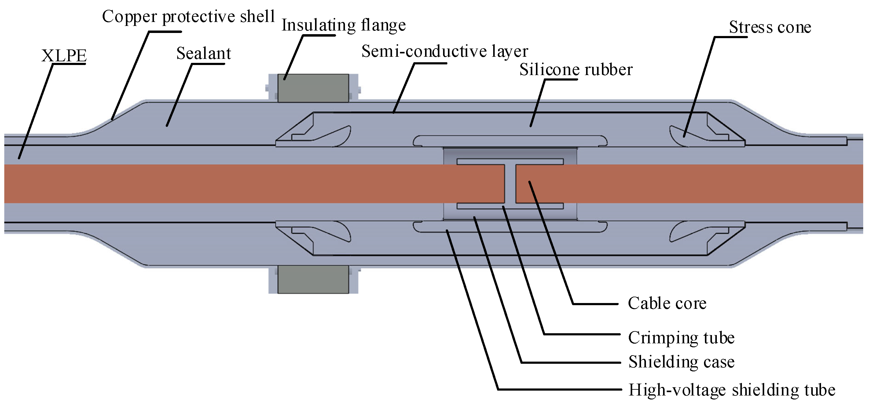
2. Composition of Cable Systems and Structure of Cable Joints

The cable system is an important component of modern power transmission systems, mainly consisting of the cable body, cable accessories, and cable auxiliary facilities. Cable accessories include cable intermediate joints, terminals, and others; cable auxiliary facilities mainly include cable tunnels, cable shafts, ducts, and cable trenches. High-voltage cables are generally composed of single-core cross-linked polyethylene (XLPE) cables. If the cable length is too long, it can lead to difficulties in transportation, increased installation challenges, and issues such as excessively high induced voltage on the metal sheath [14]. Typically, the single-section laying length of high-voltage single-core cables is around several hundred meters [15], so it is necessary to connect the cable sections using cable joints to meet the power transmission requirements.
Based on the design of the cable intermediate joint structure, materials used, molding methods, and installation processes, they are mainly classified into four types: wrapped type, heat-shrinkable type, cold-shrinkable type, and prefabricated type. (1) The wrapped-type cable intermediate joint can be made by wrapping rubber–plastic insulating tapes and semi-conductive tapes around the target cable, depending on the voltage level. Its advantage is that it is flexible in installation and not limited by the voltage level. However, the manufacturing process of the wrapped-type cable joint is relatively complex and requires high technical skills from on-site construction personnel [16,17]. (2) The heat-shrinkable cable joint is made by placing pre-treated heat-shrinkable tubing onto the processed cable, followed by the use of heat to shrink the material, completing the cable accessory manufacturing process. Its advantages are its low cost and simple installation. However, its performance can easily be affected by the temperature during the manufacturing process and the quality of the heat-shrink material, resulting in lower quality and reliability. It is typically used for medium- and low-voltage cables [18]. (3) The insulating material used for cold-shrinkable cable joints is typically high-temperature vulcanized silicone rubber. During the manufacturing process of cold-shrinkable products, the material is first expanded, and a spiral liner made of nylon strips is placed inside. The installation method involves placing the pre-expanded cable joint onto the cable and then removing the nylon spiral liner. At this point, the external body made of synthetic rubber will automatically shrink and tightly adhere to the cable, completing the manufacturing of the cable joint [16]. (4) The insulating material used for prefabricated cable joints is also typically high-temperature vulcanized silicone rubber, and they are divided into combination prefabricated cable joints and integral prefabricated cable joints. Since combination prefabricated cable joints require on-site assembly of the components, poor sealing could lead to moisture ingress at the joint. The integral prefabricated intermediate joint has a compact design and simple structure, offering advantages such as easy installation and high reliability. Therefore, for 110 kV and 220 kV cable joints, the integral prefabricated cable joint is primarily used. As a result, the following will provide a detailed introduction to the integral prefabricated high-voltage cable intermediate joint [4].
The structure of the 220 kV integral prefabricated cable intermediate joint is shown in Figure 1. This joint is a 220 kV integral prefabricated silicone rubber insulated cable intermediate joint, with two protective copper shells of the intermediate joint connected together by an insulating flange.
The crimping tube tightly connects the conductors of the two sections of the cable core through the crimping process. It needs to withstand the current transmitted through the cable, so it is required to have good electrical conductivity and mechanical strength.
The stress cone is typically made of semi-conductive materials. Its main function is to uniformly distribute the electric field strength at the end of the cable’s main insulation shielding and strengthen the insulation in that area. The tail of the stress cone is crimped at the interface between the cable’s main insulation and the insulation shielding layer, connecting to the insulation shielding layer and being at a low potential [19].
The high-voltage shielding tube is generally made of semi-conductive materials, primarily to uniformly distribute the distorted electric field at the cable connection. The high-voltage shielding tube connects the copper shielding case and crimping tube, maintaining the same potential as the cable core, which is the high-voltage potential [20]. It not only ensures uniform distribution of the electric field but also reduces electromagnetic interference to the external environment.
The main insulation component is the core part of the cable intermediate joint, primarily composed of high-temperature vulcanized silicone rubber. Its main function is to prevent external impurities such as air and moisture from entering the cable, which could accelerate cable aging, while also providing sufficient insulation and support.
The protective copper shell is reliably grounded and is typically placed outside the main insulation component of the cable joint. The gap between the protective copper shell and the main insulation component is filled with sealant. The sealant is typically made of organic materials such as epoxy resin or polyurethane, and it possesses good sealing, waterproof, and insulating properties [21].

3. Spatial and Temporal Process of Cable Joint Explosion

Many scholars have studied the explosion mechanism of cable joints, with most believing that arc breakdown is the direct cause of cable joint explosions. Bian et al. believe that cable joint explosions are mainly caused by arc breakdown in the cable joint, generating a large amount of heat, which causes the gas near the cable core to rapidly expand, resulting in an explosion [13]. Qiu et al. believe that when a high-voltage cable joint experiences a short circuit, the short-circuit arc generates enormous energy, causing the solid materials to decompose. The gas in the sealed space rapidly expands, producing a huge shockwave that leads to an explosion [22]. Li et al. believe that when a cable joint fails and breaks down, the high-temperature arc penetrates the cross-linked polyethylene insulation, causing the material to undergo thermal decomposition and produce combustible gases. Subsequently, the radial channel continues to develop, eventually melting through the joint body and sealant, and finally making contact with the copper shell. The copper shell then undergoes high-temperature melting or is impacted by high-pressure gas, leading to the rupture of the copper shell. The combustible gases then burn violently in the air [23]. The research findings and deficiencies are summarized in Table 1.
To analyze the explosion mechanism of cable joints, the project team conducted a high-current arc impact test on 110 kV high-voltage cable joint accessories at a testing institute. A short-circuit breakdown point was artificially created from the cable core to the copper shell. After applying the test current, the high-voltage cable joint exploded and caught fire. This experiment also verified that arc breakdown is the direct cause of cable joint explosions. The explosion and fire scene of the high-voltage cable joint is shown in Figure 2.
The explosion mechanism of the high-voltage cable intermediate joint is summarized as follows: Due to the aging of the insulating material or defects in the joint, partial discharge occurs inside the joint. This partial discharge eventually develops into an arc breakdown. The high-temperature arc causes the insulating material to undergo electrical thermal decomposition, forming a plasma mixture and combustible decomposition gases. Under high temperatures, these gases are converted into high-temperature, high-pressure gases. The breakdown channel continues to develop towards the protective copper shell, causing a metallic short-circuit fault and generating a large amount of energy. The protective copper shell fractures under the impact of high-pressure, high-temperature gases. Subsequently, the combustible gases escape and undergo intense combustion in the air. In addition, overvoltage in the power system is also an important factor leading to joint failure and explosion. Particularly in cases of insufficient reactive power compensation or extremely low loads, excessively high voltage may subject the insulation material to additional electrical stress, accelerating the aging and breakdown process of the insulation material.
Although existing studies have clarified that cable joint explosions are related to factors such as insulation material aging, partial discharge, and arc breakdown, current research has not delved deeply into how these factors interact on a microscopic level and gradually evolve to cause the explosive physical process. The cable joint explosion mainly goes through several key stages: partial discharge, arc discharge, insulation material decomposition, and explosion ignition. Therefore, the following sections will review these key processes and provide a detailed analysis of the physical process of cable joint explosions.

4. Partial Discharge in Cable Joints

Cable joint explosion accidents are usually caused by the occurrence of partial discharge inside the joint. Partial discharge is a significant factor leading to the degradation of insulation materials. On one hand, the discharge is accompanied by the release of heat, which accelerates the thermal aging of the insulation material around the defect. On the other hand, the charged particles produced by the discharge continuously bombard the gas gap interface, expanding the discharge area and eventually causing insulation failure [24].

4.1. Electric Field Distribution and Weak Points Inside a High-Voltage Cable Joint

The cable intermediate joint is a weak point in the cable line, with a failure probability much higher than that of the cable body. The main reason is the complex insulation interface structure inside the cable joint. At the interfaces between different media, a phenomenon of electric field discontinuity occurs, which is especially pronounced at the tip of the interface, leading to the concentration of the electric field. The root of the stress cone is located at the interface between the main insulation of the cable body and the insulation shielding layer, where electric field distortion occurs. The high-voltage shielding tube is positioned above the crimping tube and shielding case to uniformly distribute the electric field, with field distortion occurring at its tip. Shang et al. conducted a simulation using a constant DC electric field for the accessories of the integral prefabricated high-voltage DC cable intermediate joint and concluded that the region with the maximum electric field intensity is located at the root of the stress cone and the end of the high-voltage shielding tube [20]. Additionally, the project team used COMSOL Multiphysics 5.2 finite element simulation software to model the high-voltage cable intermediate joint at a 1:1 scale and performed a two-dimensional electric field simulation. The electric field distribution of the high-voltage cable intermediate joint is shown in Figure 3 below. The results indicate that the maximum field strength occurs at the root of the stress cone and the saddle-shaped corner of the high-voltage shielding tube, with electric field magnitudes of 1.78 × 10⁷ V/m and 4.2 × 10⁷ V/m, respectively.
During the installation of cable accessories, a layer of silicone grease is typically applied between the interface of the XLPE insulation and silicone rubber (SiR) to enhance the sealing and lubricating properties of the interface. However, the swelling effect of the silicone grease can damage the cross-linked structure of the silicone rubber, which in turn reduces the insulation performance and long-term reliability of the cable accessory [25]. In addition, Du et al. found that the initial discharge voltage of the XLPE-SiR insulation interface increases with the increase in interface pressure. The aging and relaxation of the silicone rubber may reduce the interface pressure, which in turn can lead to interface discharge between XLPE and SiR [26]. Once this interface discharge connects the high-voltage shielding tube and the stress cone, it can lead to the insulation failure of the cable joint. A sketch of the discharge path on the interface is shown in Figure 4.
Therefore, the weak points inside the cable joint are the stress cone, high-voltage shielding tube, and the XLPE-SiR interface. Once defects occur in the cable joint, these areas are prone to partial discharge, which may lead to insulation breakdown and other failures, thus affecting the safe and stable operation of the cable.

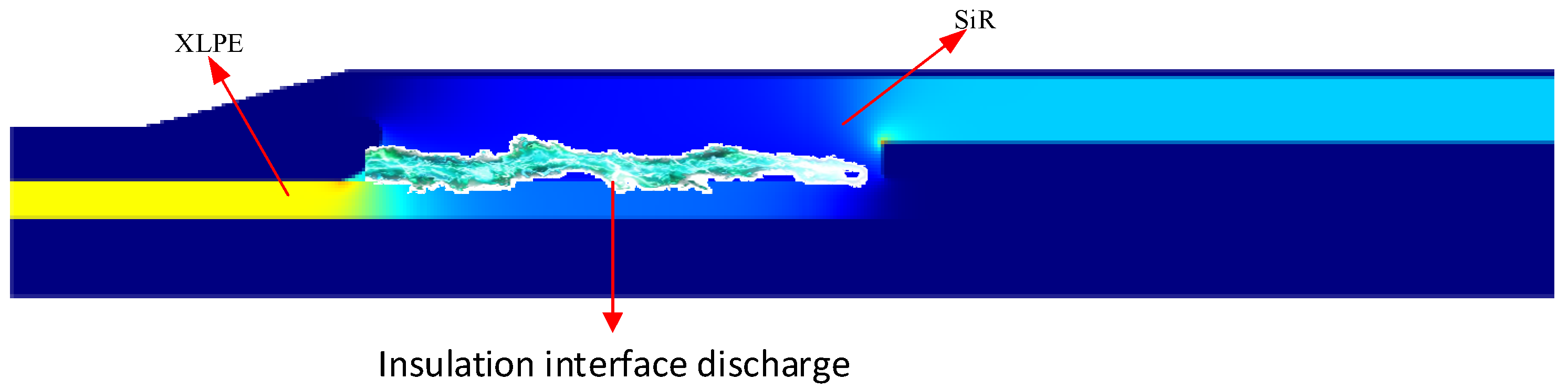
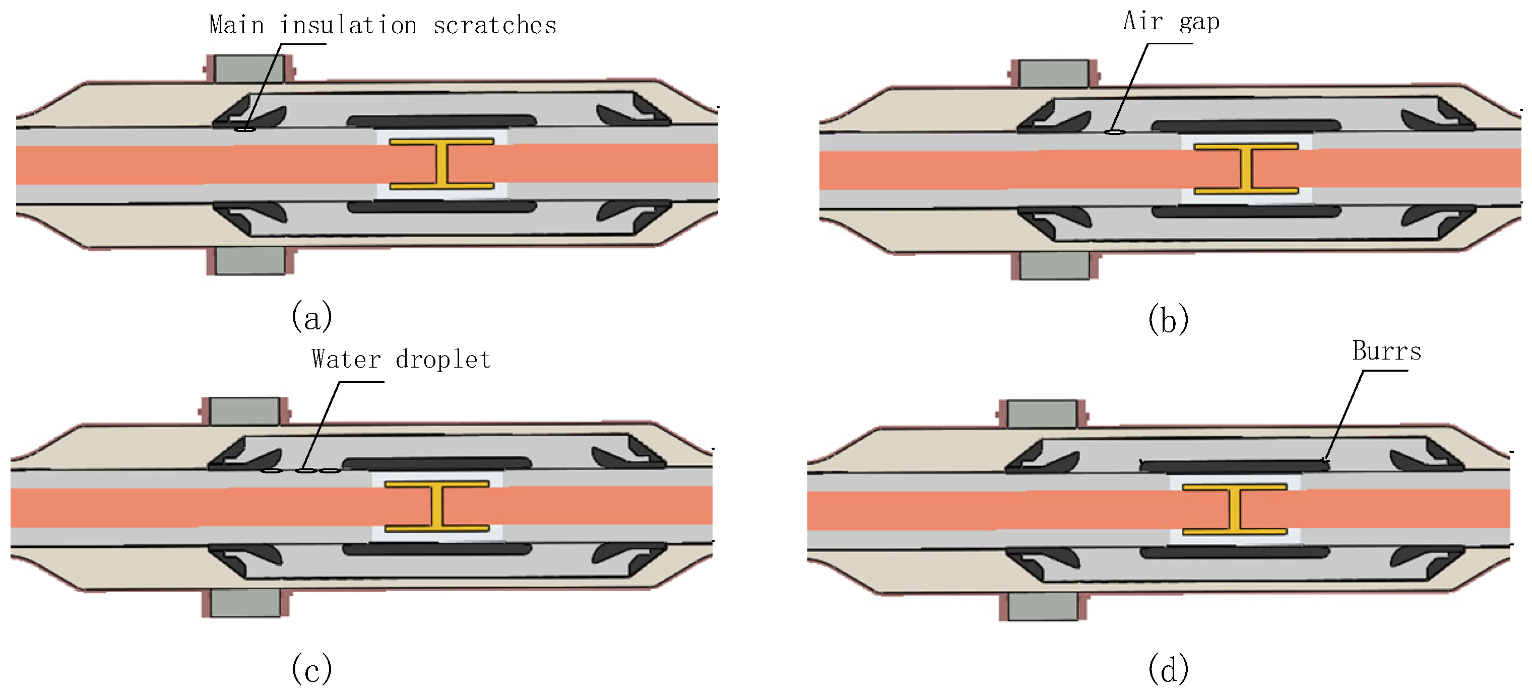
4.2. The Causes of Partial Discharge in Cable Joints

For the commonly used integral prefabricated cable joints, defects may occur during the manufacturing or installation process [27]. For example, during the on-site installation of cable joints, the outer shielding layer of the cable body is stripped, and the prefabricated joint body is assembled. If the installation process is not performed properly, even minor operational mistakes can cause scratches on the surface of the main insulation, leading to gas gap defects. The dielectric constant of the gas is much lower than that of the surrounding insulating materials, which makes it more prone to partial discharge under the influence of voltage. Common defects in cable joints also include gas gaps at the joint interface, water ingress into the joint, and burrs in localized areas of the prefabricated rubber components [28,29]. Some common defects of cable joints are shown in Figure 5.
Currently, most studies on the internal electric field distribution of cable joints with defects use finite element software for electric field simulation. Xiang et al. created through defects in the outer semi-conductive layer of high-voltage cable prefabricated intermediate joints and conducted electric field simulations. They found that the maximum electric field strength inside the air gap exceeded the breakdown strength of air. Discharge starts from the gas cavity in the outer semi-conductive layer, and if the discharge continues, it can lead to the formation of a through-discharge channel, resulting in insulation failure [29]. Liu et al. conducted electric field simulations and experimental verification on two types of defects—air gaps and improper winding of insulating tape—between the crimping tube and the high-voltage shielding tube. The results showed that the maximum electric field strength for both types of defects was more than twice the normal maximum field strength in the joint. When there was an air gap between the connecting tube and the inner stress cone, the local field strength exceeded the ionization field strength of air, which could easily lead to breakdown of the air gap [30]. Zhao et al. created four types of defects, including edges and burrs on the surface of the crimping tube, and conducted electric field simulations and experimental verification. The results showed that all of these process defects caused local field strength distortion, making the defect areas the weak points of the joint and increasing the risk of partial discharge [31].
In the simulation analysis of cable joints, there is a coupling relationship between the electrical and thermal fields. The electromagnetic losses in the electromagnetic field affect the temperature calculation, and changes in temperature, in turn, influence the dielectric constant of the materials. Wei et al. considered the electro-thermal coupling effect and analyzed the impact of three defects—conductive impurities, water droplets, and air gaps—on the electro-thermal field of cable joints. The results showed that all three defects cause distortion of the local field strength and temperature, with the air gap defect having the most significant impact [32]. Liang et al. used finite element software to establish an electro-thermal–stress coupling model for the compression defects in 220 kV high-voltage cable joints. They found that compression process defects lead to secondary distortion of interface stress, accelerating the aging of insulation materials, which is a key cause of breakdown at the intermediate position of the cable joint [33]. The electric field simulation results of cable joints with different defect types are shown in Table 2.
In addition, studies have shown that when energizing an unloaded cable line without residual charge before switching, the switching overvoltage at the cable joint conductor at the end of the line can reach up to 2.11 p.u. At the moment of the circuit breaker closing, the electric field strength at the XLPE-SiR interface and the high-voltage shielding tube end in the most affected joint increases by nearly 100% compared to normal conditions without overvoltage, exceeding the safe operating threshold of the interface electric field [34,35]. Overvoltage increases the electric field strength, making pre-existing weak insulation defects within the cable joint more prone to partial discharge.
Many scholars have conducted simulation analyses of typical defects in high-voltage cable joints and constructed simulation models for cable joints. However, there are still the following shortcomings: ① The types of defects in high-voltage cable joints are diverse, and existing simulations often focus on only a few typical defects, failing to fully cover all possible defect types and their combinations. ② Some studies only consider a single type of defect, while neglecting the situation when multiple defects coexist, which does not fully align with the reality of cable joint defects, as defects in actual joints are random and complex.

4.3. Detection Methods for Cable Joint Defects

Partial discharge in cable joints is mainly caused by various defects in the joints. Over time, it leads to insulation material aging, ultimately resulting in short circuit breakdown, and in severe cases, even explosion of the joint. If defects in the cable joint can be effectively detected during the partial discharge period and handled promptly, it can greatly reduce losses caused by cable failures. Partial discharge detection technology, with its high sensitivity and excellent ability to precisely locate defects, is the most widely used and effective method for detecting XLPE cable insulation defects [36]. The main methods for partial discharge detection currently include the high-frequency current transformer (HFCT) method, ultra-high-frequency (UHF) method, and acoustic emission (AE) method.
(1) The HFCT method installs an HFCT on the grounding line or cable body of the cable joint to capture the high-frequency current pulse signals generated by partial discharge from the coupling loop. The advantages of the HFCT method are that the HFCT is easy to install and its signal bandwidth can be adjusted as needed. However, it is only applicable to cases with a grounding line and has relatively poor anti-interference capability [37]. (2) The UHF method is a detection technique based on the electromagnetic wave signals generated by partial discharge. By installing a UHF antenna at the cable joint, the method couples the electromagnetic wave signals generated by partial discharge. The detectable range of the UHF method is from several hundred MHz to a few thousand MHz, which helps effectively avoid low-frequency noise interference and improves detection sensitivity. However, UHF signals attenuate rapidly as they propagate along the cable, making long-distance monitoring difficult [38]. (3) The AE method is a technique for identifying partial discharge by detecting the acoustic signals generated during the partial discharge process. This method uses piezoelectric sensors to capture the acoustic signals and convert them into electrical signals for analysis. The AE method is less affected by external electromagnetic noise, but since the acoustic signals attenuate quickly during propagation, it is mainly applied for detecting partial discharge at the cable joints and nearby areas [39]. In addition, there are other detection technologies for cable insulation defects, such as damping oscillation wave detection, temperature measurement technology, and cable monitoring technology based on Optical Current Transformers [40,41,42]. The advantages and disadvantages of partial discharge detection technologies are summarized in Table 3.
Jiang et al. designed and constructed five typical defects of 110 kV high-voltage cable joints, established a partial discharge testing platform, and obtained partial discharge signals under different defects through the capacitive coupling method. They constructed three-dimensional phase-resolved partial discharge (PRPD) spectra and found that under power frequency voltage excitation, the discharge pulse sequence, discharge interval, and discharge repetition rate of these five typical defects varied significantly. These characteristics can be used as the basis for discharge type identification [43]. Zhou et al. fabricated 11 typical defects located in the cable body, high-voltage cable joints, and other parts. Using methods such as the HFCT method and temperature measurement technology, they established a library of partial discharge spectra, grounding current variation curves, and temperature rise variation curves. They also developed a diagnostic and evaluation process for high-voltage cable defects and proposed a comprehensive evaluation method for the condition of high-voltage cables based on multi-state features and variation patterns [44]. Tang et al., based on two non-electrical partial discharge detection technologies, ultrasound and ultraviolet, designed and implemented a combined acoustic–optical partial discharge detection system for high-voltage cable joints, which can provide real-time early warning for partial discharge [45].
Currently, most studies on cable joint defect characteristics involve artificially creating joint defects and measuring them in the laboratory to obtain partial discharge characteristic maps for different defects. These maps serve as a reference for identifying defect types in actual production. However, there are still the following shortcomings: (1) The defects artificially designed are mostly single defects, while in actual operation, cable joints may have multiple coupled defects. Therefore, the partial discharge characteristic maps obtained from experiments may differ from real-world scenarios. (2) The aforementioned experiments are mostly conducted in the laboratory, and the environment and voltage conditions may not fully align with those in actual field situations. Therefore, the typical maps obtained through simulation experiments at this stage can only be used for preliminary judgment of defect types.

5. Arc Breakdown in Cable Joints

When partial discharge in the cable joint reaches a certain level, and the damage to the insulation material reaches a critical threshold, the electric field intensity exceeds the insulation material’s withstand capacity, causing the insulation layer to break down and form an arc discharge. The arc breakdown releases a significant amount of energy, and the thermal effects cause the insulation material to decompose, generating characteristic gases. Under high temperatures, these gases transform into high-temperature, high-pressure gases. The protective copper shell fractures due to the impact of the high-temperature, high-pressure gases, and the flammable gases escape from the protective copper shell and ignite in the air. It can be seen that arc breakdown is the direct cause of cable joint explosions, and the gases generated by the decomposition of insulation materials are the key factor in the explosion. Therefore, this chapter first introduces the breakdown path of the arc in the cable joint and commonly used arc simulation models, followed by an analysis of the gas composition produced by the decomposition of insulation materials. Finally, the joint explosion and impact process are discussed, leading to the inference of the complete physical process of cable joint failure from partial discharge to explosion.

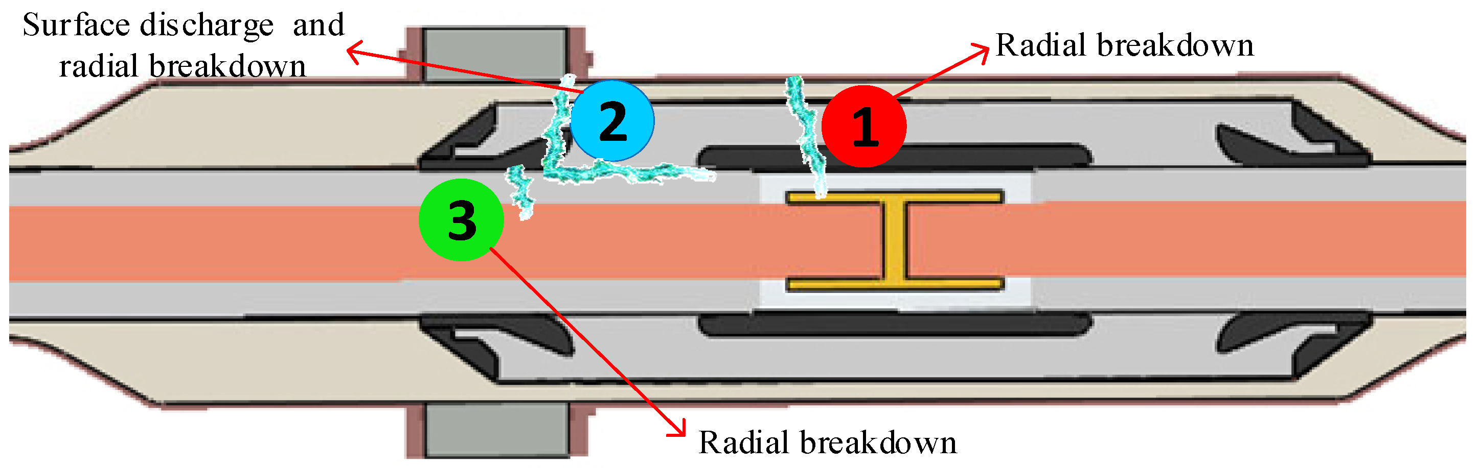
5.1. Arc Breakdown Path and Arc Simulation Models

Through the dissection analysis of multiple high-voltage cable joint explosion accidents, three main paths for the development of arc breakdown have been summarized: (1) Radial breakdown occurs directly between the crimping tube or cable core and the copper sheath. (2) Surface discharge occurs between the high-voltage shield and the stress cone, which then radially develops until it reaches the protective copper shell. (3) Breakdown occurs between the cable core and the stress cone, usually caused by field concentration due to misalignment of the stress cone [23,46]. Therefore, the discharge path inside the joint includes both axial discharge and radial discharge, as shown in Figure 6.
The main cause of radial discharge is that the high-voltage shielding tube is a weak point in the joint, with high electric field intensity. Over long-term operation, the physical cross-linking structure of the SiR near the high-voltage shielding tube may be damaged, triggering the growth of electrical tree branches [47]. These tree branches will continue to develop radially, increasing in number and length, eventually causing the insulation of SiR to break down and leading to the discharge channel extending to the copper shell. Axial discharge occurs due to defects such as water ingress or aging of the insulating material, which reduces the breakdown voltage between the XLPE-SiR interface. This leads to the phenomenon of interface discharge between the high-voltage shielding tube (high potential) and the stress cone (low potential) [48,49]. Once partial discharge develops into arc discharge, the immense energy generated can potentially cause the cable joint to explode.
Currently, there are two main approaches for establishing arc models: one is the physical–mathematical model, based on the various physical processes of the arc and their mathematical descriptions; the other is the black-box model, which only describes the external volt–ampere characteristics of the arc. The physical–mathematical model is rigorously derived with clear physical concepts, but determining its boundary conditions requires a large amount of experimental data support, or otherwise it is difficult to implement. On the other hand, the black-box model has a simple mathematical expression, which greatly simplifies the arc process. It focuses only on the external characteristics of the circuit, avoiding the complex descriptions of the physical–mathematical model [50]. Due to the complexity of the arc, black-box models are generally used to describe it. Classic black-box models include the Cassie model and the Mayr model. Additionally, there are control theory models, modified versions of the Mayr model using various methods, and black-box models based on other theories [51,52,53]. In recent years, magnetohydrodynamic models and piecewise linear arc models have also been widely applied [54,55].
  • Cassie model:
The Cassie model assumes that the gas channel of the arc is cylindrical, and that this gas channel has extremely strict boundaries. The diameter of the arc changes with the current, but the arc temperature remains constant [56]. The rate of energy dissipation is related to the change in the cross-sectional area of the arc column, and the Cassie model is shown in Equation (1):
1 g c d g c d t = 1 τ c ( u 2 U c   2 1 )
In the formula, u is the arc voltage during the arc process; gc is the arc conductance in the Cassie model; τc is the arc time constant; and Uc is the static voltage of the arc. The Cassie arc model is more suitable for arc plasma in a low-resistance state before the current zero crossing.
2.
Mayr model:
The Mayr model is a dynamic arc model based on the theories of thermal ionization, thermal inertia, and thermal equilibrium [50]. The Mayr model is shown in Equation (2):
1 g m d g m d t = 1 τ m e i N 0 1
In the equation, e represents the arc potential gradient; gm is the arc conductance in the Cassie model; τm is the arc time constant; i is the arc current; and N0 is the power of arc cooling. The Mayr dynamic arc model is suitable for describing the actual behavior of arc plasma in a high-resistance state.
3.
Control Theory Arc Model.
In the Mayr arc model, by introducing variables such as arc length, the mathematical expression of the control theory arc model is derived as shown in Equation (3):
d g d t = 1 τ s ( G s g )
In the equation, g represents the instantaneous arc conductivity, Gs represents the steady-state arc conductivity, and τs represents the arc time constant.
The empirical formulas for the steady-state arc conductivity Gs and the arc time constant τs are given by Equations (4) and (5), respectively.
G s = | i | V s × l
τ s = α × I s l .
In the formula, i represents the instantaneous arc current, Vs is the voltage drop per unit arc length, l denotes the arc length, Is is the arc current amplitude, and α is the empirical coefficient, usually taken as 2.85 × 10⁻⁵.
Currently, scholars studying the arc models of cable joints base their research on existing arc models to simulate and model the arc in cable joints. Qiu et al., based on the magnetohydrodynamic model, used a multi-physics field-coupled finite element calculation method to simulate the insulation arc breakdown characteristics of a 220 kV high-voltage cable joint. They calculated the physical parameters of fault arcs under different conditions and studied the relationship between arc energy, short-circuit current, and other load characteristics [57]. Wang et al., using a 15 kV XLPE cable joint as an example, established a finite element calculation model and concluded that when the insulation material inside the cable joint undergoes arc breakdown, it leads to a certain temperature rise and significant thermal stress [58]. Liu et al. used the Mayr arc model to simulate early cable faults and proposed an early fault location algorithm [51].
Due to the randomness of the actual arc, there is a certain discrepancy between the above simulation methods and the actual arc signals. Therefore, to obtain an accurate arc model for cable joints, a large amount of experimental data are needed to calibrate the model or propose a more refined new method to simulate the arc.

5.2. Thermal–Electric Decomposition of Insulation Materials

After the formation of the arc breakdown channel, the heat generated by the high-temperature arc causes the XLPE and SiR insulation materials to undergo thermo-electric decomposition, producing characteristic gases. The composition of these characteristic gases is crucial for analyzing the explosion and combustion process in high-voltage cable joints.
Huang et al. used molecular dynamics simulation to reveal the pyrolysis and gas generation mechanisms of XLPE at the atomic and free surface level. The simulation results showed that the thermal decomposition of XLPE generates hydrocarbon gases and carbon oxides, and the reliability of the simulation results was verified through experiments [59]. Yuan et al. simulated the characteristic gas generation process of different types of XLPE cable faults through experiments. The results showed that the gas products of XLPE partial discharge were only CO and CO2. The gas products of XLPE arc discharge (with arc currents of 30, 35, and 40 mA) included CO, CO2, CH4, C2H6, C2H4, C2H2, and H2. XLPE low-temperature pyrolysis only produced CO, while high-temperature pyrolysis also generated CO2, H2, CH4, and C2H6 [60]. Wan et al. found that XLPE cables, when overheated, would decompose and produce gases such as C2H4, C2H6, C3H6, and C3H8 [61]. Wang et al. conducted simulation research on the thermal decomposition of silicone rubber materials under a rapid temperature rise using the ReaxFF model. The results indicated that under conditions of 4000–10,000 K, the main products at different stages of decomposition were CH4, H2, C2H4, C2H2, and H2O. The electric field could lower the decomposition temperature and accelerate material aging [62]. Cao et al. studied the thermal degradation products of discarded silicone rubber composite insulators at different temperatures (300 °C, 400 °C, 500 °C, 600 °C). They found that at lower temperatures, the main decomposition products of silicone rubber were a series of dimethylsiloxane cyclic compounds, along with a small amount of chain-like siloxanes [63]. Gas pyrolysis products of XLPE and SiR are shown in Table 4.
The project team created an XLPE-SiR flat panel and conducted discharge thermal cracking experiments. The gas composition and content proportions of the gases collected from the thermal decomposition of insulating materials under discharge were analyzed using gas chromatography–mass spectrometry (GC-MS), obtaining the major gas composition percentages as shown in Figure 7.
There is more research on the thermal decomposition of XLPE materials for cables, but less research on the thermal decomposition of silicone rubber in high-voltage cable joints. Most scholars focus on analyzing the products under electrical or thermal conditions separately. However, the thermal decomposition of insulating materials caused by arc breakdown in high-voltage cable joints is an electro-thermal coupled process, which requires considering the interaction between both. Additionally, when conducting experiments on gas composition and content, real cable joints should be used. How to construct the arc channel, simulate arc breakdown, and obtain characteristic gas components are issues that need to be addressed in future research.

5.3. Explosion and Impact Process of Cable Joints

The explosion of the high-voltage cable intermediate joint is caused by the arc discharge, which releases a large amount of energy instantaneously, generating an arc shock force. The temperature of the arc channel can reach several thousand to tens of thousands of Kelvin [64], and the intense molecular thermal motion causes the gas near the arc region to expand outward at supersonic speeds, forming an explosive shockwave. Drabkina was the first to link plasma motion with shockwave theory [65]. Neumann [66], Sedovl [67], Taylor [68], and others, based on self-similarity theory, studied medium-strength explosive waves and analyzed the attenuation laws of medium-strength explosive waves near the explosion source. Bethe, Whitham, and Jones conducted research on the propagation characteristics of weak shockwaves, extending their work to the field of arc-induced explosions. To unify the different explosion sources and environmental media in various studies, a characteristic radius R0 was defined. Using R0, dimensionless parameters x and τ were introduced, where x represents the dimensionless parameter for the explosion wave radius, and τ represents the dimensionless parameter for time. The calculation formulas for R0, x, and τ are given by Equations (6)–(8), respectively.
R 0 = n + 2 2 2 E 0 B γ P 0 1 n
τ = α 0 t 0 R 0
x = R R 0
α0 is the speed of sound in undisturbed medium; R is the distance between the measurement point and the explosion source; t0 is the time it takes for the explosion wavefront to reach the point at distance R; n = 1, 2, 3 corresponds to plane, cylindrical, and spherical explosion waves, respectively; E0 is the explosion wave energy; B is a constant related to the geometry; γ is the specific heat ratio of the medium; and P0 is the ambient pressure.
According to the derivation in reference [69], the expressions for the explosion shockwave energy induced by arc discharge for medium-strength waves and weak waves are given by Equations (9) and (10), respectively.
E 0 = B γ ( γ + 1 ) 2 γ R n Δ P
E 0 = P 0 B γ 2 / ( n + 2 ) 2 R n h 1 c P 0 Δ p 2 γ γ + 1 2 n + 2 2 + 1 2 n 2 2 n 1 1
C = 2 n 2 2 n 1 2 n + 1 2 n 2 2 n + 1
In the formula, ΔP represents the overpressure of the shockwave.
Since the energy of the arc shockwave is related to factors such as the current waveform and the rate of current rise, it is not easy to calculate precisely using theoretical formulas. Yang et al. designed a 50 kA/200 ms high-current artificial short-circuit arc test and measured the overpressure value of the explosion shockwave released from the energy-dissipating hole of the 220 kV high-voltage cable joint protection device. Through simulation, the explosion wave energy of the short-circuit arc in the 220 kV high-voltage cable joint was back-calculated [70]. Xu et al. measured the overpressure of the shockwave generated when the high-voltage cable joint exploded in air. By using TNT to replace the cable joint explosion, they simulated the equivalent shockwave peak of the cable joint explosion and obtained the pulse overpressure peak distribution within a blast distance range of 0.4 m to 5 m [71]. It can be seen that the existing experiments measuring the explosion of high-voltage cable joints all calculate the explosion wave energy of the short-circuit arc or the distribution of shock overpressure peak values around the explosion center through indirect methods, which may involve some errors.
Based on the previous analysis, the explosion–combustion process of the high-voltage cable joint can be described as follows: due to the aging of the insulating material or defects in the cable joint manufacturing, partial discharge phenomena occur. After prolonged operation, partial discharge develops into arc breakdown, releasing a large amount of energy. The coupling effect of a high temperature and electric field causes XLPE and SiR to undergo electro-thermal cracking, generating high-temperature, high-pressure combustible gases such as CH4 and H2. Subsequently, the breakdown channel develops to the copper shell, which ruptures under the impact of high-temperature and high-pressure gases. The combustible gases escape from the copper shell, react with oxygen in the air, and ignite violently.

6. Fire and Explosion Prevention Measures

The explosion wave and debris generated during a joint explosion are likely to threaten the personal safety of on-site personnel. The fire caused by the explosion may ignite surrounding cable lines, resulting in immeasurable damage. Therefore, fire and explosion prevention measures are required to reduce the harm. Common fire and explosion prevention measures for high-voltage cable joints include fire- and explosion-proof partitions, joint protection boxes, and fire- and explosion-proof blankets [72]. A certain number of energy dissipation holes are designed on the outer shell of the joint protection device, and during an explosion, the energy dissipation holes rapidly release high-pressure gas in an empty space, which is also a commonly used explosion protection method [73].
Fire- and explosion-proof partitions are generally installed around the cable joint to isolate the joint from the cable body. When in use, they are typically combined with fire-extinguishing pellets to achieve better fire and explosion prevention effects [74]. Common cable joint protection boxes include flame-retardant plastic protection boxes, fiberglass protection boxes, and aluminum–magnesium alloy protection boxes. Flame-retardant plastic protection boxes are usually semi-enclosed, offering poor fire and explosion protection, but are inexpensive [75]. Fiberglass is a reinforced material made from composite materials such as glass fibers, epoxy resin, and unsaturated resin [76]. During joint explosions, fiberglass protection boxes generally cannot withstand the instantaneous shock of the explosion. The shell is brittle and fragile, providing moderate explosion protection and is relatively expensive. Aluminum–magnesium alloy protection boxes are non-magnetic, elastic, and have high strength, offering good fire and explosion protection. Protection boxes usually occupy a large space, so they are rarely used in cable tunnels. Additionally, the installation of protection boxes can lead to an increase in joint temperature and a decrease in current-carrying capacity [77]. Flexible fireproof blankets are commonly used in narrow cable tunnels due to their advantages of easy installation and small space occupancy. However, their price is several times higher than that of fireproof coatings. When used, they are typically combined with explosion-proof blankets to achieve both fire and explosion protection [75]. Fire and explosion prevention measures and their advantages and disadvantages are summarized in Table 5.
Ding et al. designed an aluminum–magnesium alloy fire- and explosion-proof protection box for high-voltage cable joints, and through experimental verification, they concluded that the protection box provides good fire and explosion protection performance [76]. Xu et al. studied the effect of fiberglass protective shells on the thermal field of cable joints and found that the installation of fiberglass protective shells increases the axial and radial temperature differences, reducing the current-carrying capacity of the cable joint [78]. Bian et al. analyzed the performance of a cable joint explosion-proof device through finite element simulation, and the results showed that the device can withstand the impact of an explosion and has little effect on the temperature rise of the cable joint [13]. Xiao et al. used finite element software to theoretically analyze the heat transfer characteristics of cable joints with added protective boxes. They proposed two cooling measures: filling the protective box with a thermally conductive gel or adding fans to the cable body section. The results showed that both measures can significantly reduce the conductor temperature of the cable joint [79]. Cao et al. developed a flexible joint explosion-proof bag, which occupies little space and prevents air from entering during an explosion, effectively preventing the occurrence of fires [80]. Liu et al. verified whether common explosion-proof measures such as fire- and explosion-proof partitions and joint protection boxes are effective through cable joint short-circuit fault tests. The results showed that the existing explosion-proof measures could not withstand the short-circuit current impact and sustained combustion in the test. Currently, there is still a risk of cable joint explosions igniting cable groups in the cable tunnel [72]. Yang et al. designed a spring contraction energy dissipation method, which solves the issue of reduced waterproof and moisture-proof performance caused by the venting holes in the aluminum–magnesium alloy protection box [81].
Common fire and explosion prevention measures need further improvement in performance. When developing cable intermediate joint explosion-proof products with complete fire and explosion prevention capabilities, it is essential to ensure they can withstand the impacts and destruction caused by high temperatures and high pressure. Additionally, current explosion-proof measures mainly focus on minimizing the adverse consequences after a joint explosion. Future solutions could aim to fundamentally prevent explosions by concentrating on how to suppress the development of electric arcs or by working in conjunction with relay protection. This would ensure that the relay protection reliably operates before the joint explodes, preventing the cable joint from detonating.

7. Conclusions

This paper reviews the explosion mechanism and explosion-proof measures of high-voltage cable intermediate joints, providing a comprehensive analysis of the development process from partial discharge to arc breakdown, insulation material pyrolysis, explosion, and combustion in cable joints, as well as the corresponding explosion-proof measures. The aim is to provide a theoretical foundation and technical reference for future research. The main conclusions and outlook are as follows:
(1)
The explosion of cable joints often starts with partial discharge, which is a key factor in the degradation of insulation. The heat and charged particles generated by partial discharge accelerate insulation aging, expand the discharge area, and eventually lead to insulation failure. Defects in cable joints, such as air gaps, burrs, and scratches, can trigger partial discharge. Currently, various detection methods, including high-frequency current, ultra-high-frequency, and acoustic emission methods, are widely used to detect joint defects. However, these methods face challenges, such as being easily disturbed by external factors and lacking sufficient accuracy in identifying defect types. In the future, further improvements in the accuracy and practicality of detection technologies are needed to enable effective early identification of defects.
(2)
Partial discharge, when developed to a certain extent, can lead to arc breakdown, releasing a large amount of energy and causing the insulation material to decompose and produce characteristic gases. The arc breakdown path includes both radial and axial discharge, yet the research on arc models is still incomplete and requires more experimental data for calibration. Studies on the decomposition of insulation materials have primarily focused on XLPE, with relatively fewer studies on silicone rubber, and most of these analyses have been based on single factors. Future research should consider the electro-thermal coupling effect to more accurately simulate real operating conditions. Additionally, to more precisely obtain the composition and proportion of decomposition products from insulation materials, experiments using actual cable joints should be conducted.
(3)
The explosion of high-voltage cable intermediate joints generates intense shockwaves and flying debris, posing a threat to the safety of on-site personnel and potentially causing fires. Existing fire and explosion protection measures, such as fire- and explosion-proof partitions, joint protection boxes, and fire- and explosion-proof blankets, mainly focus on reducing the impact of explosions, with limited explosion-proof capabilities. Future research and development should focus on fundamentally preventing explosions, such as inhibiting arc development or coordinating with relay protection to ensure reliable operation of relay protection before joint explosion. At the same time, when developing cable joint explosion-proof products with complete fire and explosion protection functions, it is essential to ensure their ability to withstand high-temperature and high-pressure impacts and destruction.

Author Contributions

Conceptualization, W.Q., C.L. and Y.H.; methodology, W.Q. and J.C.; validation, N.C., Y.H. and Z.J.; investigation, Z.J. and J.C.; resources, W.Q. and C.L.; writing—original draft preparation, N.C. and P.W.; writing—review and editing, P.W. and G.L.; visualization, N.C. and J.C.; supervision, G.L. All authors have read and agreed to the published version of the manuscript.

Funding

This research is supported by the Project of Zhuhai Power Supply Bureau of Guangdong Power Grid Limited Liability Company (030400KK52220007 (GDKJXM20220322)).

Data Availability Statement

Not applicable.

Acknowledgments

The authors gratefully acknowledge the support of the Guangdong Key Laboratory of Efficient and clean Energy Utilization, South China University of Technology, Grant/Award Number: 2008A060301002.

Conflicts of Interest

Authors Wei Qiu, Chen Li, Yuhua Huang, Zhibin Jiang, Jiangjing Cui were employed by the company Zhuhai Power Supply Bureau of Guangdong Power Grid Limited Liability Company. The remaining authors declare that the research was conducted in the absence of any commercial or financial relationships that could be construed as a potential conflict of interest.

Abbreviations

The following abbreviations are used in this manuscript:
XLPECross-linked polyethylene
SiRSilicone rubber
HFCTHigh-frequency current transformer
UHFUltra-high frequency
AEAcoustic emission
GC-MSGas chromatography–mass spectrometry

References

  1. Wei, F. Design of Transmission Line Based on High Voltage Cable. Electron. Technol. 2022, 51, 266–267. [Google Scholar]
  2. Guo, W.; Zhou, S.; Wang, L.; Pei, H.; Zhang, C. Design and Application of Online Monitoring System for Electrical Cable States. High Volt. Eng. 2019, 45, 3459–3466. [Google Scholar]
  3. Li, S.; Wang, S.; Yang, L.; Zhao, J.; Jing, Z. Important Properties and Fundamental Issues of the Crosslinked Polyethylene Insulating Materials Used in High-voltage Cable. Proc. CSEE 2022, 42, 4247–4255. [Google Scholar]
  4. Hui, B.; Fu, M.; Liu, T.; Hou, S.; Liu, C.; Guo, J. Statistical Analysis on Failures of 110 kV and Above Power Cable System. South. Power Syst. Technol. 2017, 11, 44–50+67. [Google Scholar]
  5. Hong, J.; He, W.; He, H.; Yang, T.; Li, H. Research on Electric Field Simulation of Insulation Defects of Cable Intermediate Joints and Detection of Partial Discharge in Discharge Chamber. Power Syst. Clean Energy 2019, 35, 56–61. [Google Scholar]
  6. Huang, S. A Study on the Explosion Mechanism of a 220 kV Cable Joint in a Power Tunnel and Its Countermeasures. Technol. Dev. Enterp. 2019, 35, 56–61. [Google Scholar]
  7. Huang, F.; Guo, J.; Tang, J. Analysis of Causes and Preventive Measures for the Fault of an Intermediate Joint of a 110 kV XLPE Cable. Hongshui River 2018, 37, 63–65. [Google Scholar]
  8. Kan, Y.; Gao, S.; Ren, X.; Feng, Z. Anatomical Analysis on a 220 kV Cable Intermediate Joint Fault. Hubei Electr. Power 2023, 47, 40–45. [Google Scholar]
  9. Zheng, B.; Gu, W. Cause Analysis and Measures of a 220 kV XLPE Cable Intermediate Joint Breakdown Fault. Electr. Eng. 2021, 543, 99–100+154. [Google Scholar]
  10. Guo, W.; Pu, Z.; Ren, Z.; Zhou, S.; Quan, L.; Men, Y.; Pan, Z. Analysis of Abnormal Detection Data of Fire Accident in Power Cable Tunnel and Field Test Study on Characteristic Parameters of Tunnel Fire. Front. Energy Res. 2022, 10, 860707. [Google Scholar]
  11. Jin, C. Cause of Traversing under Railway 220 kV Cable Explosion. Wire Cable 2020, 63, 37–39+44. [Google Scholar]
  12. Zeng, H. The Electric Field Distortion in 110 kV Power Cable Intermediate Joints Leading to Line Faults. Telecom World 2017, 24, 111–112. [Google Scholar]
  13. Bian, B.; Su, W.; Zhu, Z.; Ju, L.; Zhong, Q.; Zhong, Q.; Liu, J. Study on Explosion proof Technology and Temperature Rise Characteristics of 110 kV XLPE Cable Joint. J. Electr. Power 2018, 33, 278–286. [Google Scholar]
  14. Zhang, C.; Rui, H.; Liu, H.; Liu, Y. Inducted Voltage Simulation of Metal Sheath and Analysis on Maximum Allowable Laying Length for High Voltage Single⁃core Cable. High Volt. Appar. 2020, 56, 143–148. [Google Scholar]
  15. Xu, X.; Wang, B. Design of Laying Long-distance 500 kV Cable in Power Tunnel. East China Electr. Power 2010, 38, 529–532. [Google Scholar]
  16. Guan, B.; Wu, A.; Gu, Y.; Chen, H.; Yan, Y.; Dai, R.; Wu, W.; Xu, J.; Miao, J.; Wang, Z.; et al. Key Technology and Product Development of New Type Prefabricated 35 kV and Below Wrapping Middle Joint Based on Fault Analysis of Current Cable Middle Joint. Power Energy 2020, 41, 470–475. [Google Scholar]
  17. Electric Field Distribution and Structure Optimizing of Integral Prefabricated Joint and Taped Joint. J. Harbin Univ. Sci. Technol. 2018, 23, 77–81.
  18. Miao, F.; Yan, M.; Fu, P.; Han, W.; Hou, X. Charactoristics and Application of Medium Voltage XLPE Cable Heat Shrinkable Accessories. Electr. Eng. 2014, 15, 93–97. [Google Scholar]
  19. Xu, T.; Jia, C.; Xu, S. Research Method of Stress Cone Size for High Voltage Electrical Accessories—Taking 500 kV Cable as an Example. Telecom Power Technol. 2018, 35, 41–43. [Google Scholar]
  20. Shang, K.; Cao, J.; Zhao, Z.; Han, Z.; Ma, L.; Li, W. Simulation Analysis and Design Optimization of 320 kV HVDC Cable Joint. Proc. CSEE 2016, 36, 2018–2024. [Google Scholar]
  21. Zhang, W. The development of polyurethane elastic potting sealant. Adv. Mater. Ind. 2012, 41–45. [Google Scholar]
  22. Qiu, W.; Cui, J.; Huang, S.; Liu, Z.; Yang, X.; Zhong, Q.; Liang, Z. Optimum design of the front part structure of explosion-proof device for high-voltage cable joints based on multi-physics coupling. Electrotech. Appl. 2019, 38, 86–92. [Google Scholar]
  23. Li, S.; Xie, S.; Peng, Y.; Tang, W.; Zhou, H.; Fan, F. Cause Analysis on Copper Shield Burst of 110 kV Cable Joint. Hunan Electr. Power 2023, 43, 121–126. [Google Scholar]
  24. Chen, X.; Pan, C.; Wu, J.; Wu, K.; Zhang, J. Influencing Factors on Characteristics of Partial Discharge in Void of Insulating Materials. Guangdong Electr. Power 2016, 29, 86–92. [Google Scholar]
  25. Wang, Z.; Zhou, K.; Zhu, G.; Li, Z.; Fu, Y.; Wang, Z. Effect and Mechanism of Silicone Grease Swelling on Partial Discharge at Air-gap Defects of XLPE-SiR Interface. High Volt. Eng. 2021, 47, 4245–4254. [Google Scholar]
  26. Du, B.X.; Gu, L. Effects of Interfacial Pressure on Tracking Failure between XLPE and Silicon Rubber. IEEE Trans. Dielect. Electr. Insul. 2010, 17, 1922–1930. [Google Scholar] [CrossRef]
  27. Gu, L.; Zhao, A.; Hao, H.; Liu, X. Simulation Study on Effect of Defects on Temperature Distribution of Cable Intermediate Joint. Insul. Mater. 2019, 52, 69–74. [Google Scholar]
  28. Li, H.; Shen, B.; Zhou, Y.; Shen, Y.; Zou, X.; Ren, Q.; Li, X.; Huang, W. Electric Field Simulation Analysis of Typical Breakdown Mechanism of HV Cable Accessories. Power Energy 2019, 40, 649–653+659. [Google Scholar]
  29. Xiang, E.; Zhou, W.; Wang, K.; Wang, P.; Ma, Y.; Yang, N.; Zhou, Q.; Lei, Y. Discharge in High Voltage Cable Joint with Defect on Outer Semi⁃conductive Layer. High Volt. Appar. 2020, 56, 135–140. [Google Scholar]
  30. Liu, G.; Ruan, B.; Chen, Z.; Xiong, J. Analysis on the Electric Field of 10 kV XLPE Cable Joint Connecting Pipe with Air Gap Defects. Insul. Mater. 2011, 44, 62–66+73. [Google Scholar]
  31. Zhao, X.; Yang, J.; Li, S.; Shi, B.; Long, J.; Yang, H. Simulation and Partial Discharge Experimental Study on Cable Intermediate Joints with Defects. J. Henan Inst. Technol. 2024, 32, 1–7. [Google Scholar]
  32. Wei, Z.; Xu, R.; Zhang, H.; Liu, S.; Lin, G. Effects of Different Defects on the Electrical-Thermal Field Distribution Characteristics of 220 kV Cable Joints. Proc. CSU-EPSA 2025, 1–7. [Google Scholar] [CrossRef]
  33. Liang, Z.; Peng, J.; Liu, Z.; Zhong, M.; Sun, H.; Yang, X. Finite element calculation of temperature and stress variation of composite interface under high voltage cable joint crimping defects. Electrotech. Appl. 2020, 39, 60–66. [Google Scholar]
  34. Wang, H.; Wang, X.; Yu, D.; Shu, Z.; Cui, J.; Qiu, W. Study on Closing Overvoltage Simulation of 110 kV Cable Intermediate Joint. High Volt. Appar. 2021, 57, 127–134. [Google Scholar]
  35. Liu, Y.; Li, J.; Feng, X.; Li, Q.; Hui, B.; Zhang, Y. Analysis on Switching Overvoltage and Suppression Method of Cable Joint in 220 kV Cable Line. Insul. Surge Arresters 2020, 146–152. [Google Scholar] [CrossRef]
  36. Cao, J.; Jiang, Y.; Wang, S.; Zhou, X.; Li, T.; Zhou, L.; Yang, Y. Analysis and Prospect of Defect Detection Key Technology for XLPE Power Cable Joints. High Volt. Appar. 2018, 54, 87–97. [Google Scholar]
  37. Álvarez Gómez, F.; Albarracín-Sánchez, R.; Garnacho Vecino, F.; Granizo Arrabé, R. Diagnosis of Insulation Condition of MV Switchgears by Application of Different Partial Discharge Measuring Methods and Sensors. Sensors 2018, 18, 720. [Google Scholar] [CrossRef]
  38. Liu, J.; Zhang, G.; Dong, J.; Wang, J. Study on Miniaturized UHF Antennas for Partial Discharge Detection in High-Voltage Electrical Equipment. Sensors 2015, 15, 29434–29451. [Google Scholar] [CrossRef]
  39. Wu, C.; Chen, Y.; Huang, T.; Xiao, J.; Wang, C.; Zhen, W.; Chen, Y.; Cheng, Y.; Zhao, P.; Hao, Y. Overview of Condition Sensing and Detection Technology for Power Cables. High Volt. Appar. 2024, 60, 86–103. [Google Scholar]
  40. He, C.; Yuan, C.; Zeng, W.; Zhang, A. Detection Method for Partial Discharge of XLPE High-Voltage Power Cable. Power Syst. Clean Energy 2016, 32, 27–33. [Google Scholar]
  41. Xue, R.; Zhang, L.; Huang, Z.; Zhang, W.; Li, H. Comparative Study on Partial Discharge Characteristics of XLPE Cable under Damped Oscillating Wave Voltage and AC Voltage. Insul. Mater. 2015, 48, 43–48. [Google Scholar]
  42. Fotis, G.; Vita, V.; Mladenov, V. Monitoring and Digitalization Technologies for HV Power Cable Systems. In Proceedings of the 2024 16th Electrical Engineering Faculty Conference (BulEF), Varna, Bulgaria, 19 September 2024; IEEE: Piscataway, NJ, USA, 2024; pp. 1–5. [Google Scholar]
  43. Jiang, Y.; Min, H.; Xia, R.; Li, W. Capacitive Coupling Detection and Characteristic Analysis of Partial Discharge in High-voltage XLPE Power Cable Joints. High Volt. Eng. 2010, 36, 2005–2011. [Google Scholar]
  44. Zhou, L.; Cao, J.; Wang, S.; Liu, L.; Yang, Y.; Jiang, H. Comprehensive State Evaluation of High Voltage Cable Based on Multi-state Variables Characteristics and Variation Law. High Volt. Eng. 2019, 45, 3954–3963. [Google Scholar]
  45. Tang, B.; Qiu, H.; Wu, H. Design and implementation of partial discharge acousto-optic joint detection system for high voltage cable connector. Electrotech. Appl. 2021, 40, 10–20. [Google Scholar]
  46. Huang, C.; Liu, G.; Cui, J.; Qiu, W.; Wang, X.; Liu, S.; Zhao, Y.; Li, C.; Xu, X. Two Cases of Explosion in High-Voltage Cable Joints: Fault Evolution Deduction and Combustion Physical Modeling Analysis. Eng. Fail. Anal. 2025, 169, 109100. [Google Scholar]
  47. Ma, Z.; Mei, D.; Yang, G.; Xu, F.; Niu, W.; Dai, S. Effect of Voltage Frequency on the Propagation Characteristic of Electrical Tree in Silicone Rubber. Insul. Mater. 2013, 46, 57–61. [Google Scholar]
  48. Liu, Q.; Cao, W.; Shen, W.; Chen, C.; Yang, H.; Zhang, M. Influence of Material Aging on Flashover Characteristic of Cable Joint Composite Interface. Guangdong Electr. Power 2020, 33, 118–126. [Google Scholar]
  49. Huang, C.; Zhao, Y.; Hu, R.; Liu, G.; Tang, W. Moisture-induced Discharge Evolution Analysis of XLPE-SiR Insulation Interface in 10 kV Cable Joints. Guangdong Electr. Power 2024, 37, 120–128. [Google Scholar]
  50. Chen, T.; Ke, H. Modeling and Simulation of High Voltage Circuit Breaker Based on PSCAD. In Proceedings of the 2018 3rd International Conference on Communications, Information Management and Network Security (CIMNS 2018), Wuhan, China, 27–28 September 2018; Atlantis Press: Shenzhen, China, 2018. [Google Scholar]
  51. Liu, X.; Mo, F. An Incipient Fault Location Method Based on Impedance Calculation. Chin. J. Electron Devices 2022, 45, 1202–1206. [Google Scholar]
  52. Wang, R. Development of Arc Phenomenon Models. High Volt. Appar. 1991, 27, 39–46. [Google Scholar]
  53. Liu, S.; Hu, Y.; Zheng, J.; Su, X.; Xu, Y. Dynamics Simulation of 10 kV Cable Tunnel Fire for Single-phase Arc Grounding Fault. High Volt. Eng. 2021, 47, 4341–4348. [Google Scholar]
  54. Guo, W.; Wang, Y.; Huang, C.; Qin, H.; Zhang, J.; Shi, C.; Xu, Y. Research on Traveling Wave Ranging of Transient Are Breakdown Faults in Medium Voltage Cables. Power Syst. Clean Energy 2024, 40, 31–38. [Google Scholar]
  55. Wang, B.; Cui, X. Nonlinear Modeling and Analytical Analysis of Are High Resistance Grounding Fault in Distribution Network With Neutral Grounding via Arc Suppression Coil. Proc. CSEE 2021, 41, 3864–3873. [Google Scholar]
  56. Fan, J.; Ma, Y. Study on Are Modeling of Live Breaking of 220 kV Non-loaded Cable. Electr. Eng. 2018, 38–40. [Google Scholar]
  57. Qiu, W.; Cui, J.; Huang, S.; Liang, Z.; Yang, X. Finite element simulation of discharge arc characteristics of high voltage cable joints based on magneto-hydrodynamics. Electrotech. Appl. 2019, 38, 62–68. [Google Scholar]
  58. Wang, F.; Zhou, P.; Han, Y. Study on Influence of Insulation Breakdown Arc on Thermal-stress Characteristics of Cable Joints Based on Coupled Field Calculation. Distrib. Util. 2019, 36, 83–90. [Google Scholar]
  59. Huang, Y.; Zheng, Z.; Lin, Z.; Zhang, Y.; Yuan, H.; Kong, J.; Zhou, K. Molecular dynamics simulation for gassing of XLPE degradation. Eng. Plast. Appl. 2024, 52, 155–163. [Google Scholar]
  60. Yuan, H.; Zhou, K.; Kong, J.; Li, Y.; Li, Z.; Liu, C. Evolved Gas Characteristics of High-Voltage XLPE Cables Under Different Fault Conditions. High Volt. Eng. 2025, 51, 946–955. [Google Scholar]
  61. Wan, L.; Zhang, G.; Zhao, Y.; Zhao, M.; Liao, Z. Analysis of Internal Pyrolysis Characteristics of Crosslinked Polyethylene Cable. In Proceedings of the 2020 IEEE Electrical Insulation Conference (EIC), Knoxville, TN, USA, 22 June 2020; IEEE: Piscataway, NJ, USA, 2020; pp. 498–503. [Google Scholar]
  62. Wang, L.; Ma, X.; Zhang, J.; Chen, T.; Yang, S.; Yang, H. Reactive force field simulation of electrothermal cracking of silicone rubber under steep temperature rise. Insul. Mater. 2023, 56, 59–65. [Google Scholar]
  63. Cao, H.; Wang, D.; Guo, M.; Sun, X.; Sun, T.; Du, L.; Wang, F.; Du, Z. The thermal degradation of waste silicone rubber composite insulators. J. Beijing Univ. Chem. Technol. (Nat. Sci. Ed.) 2018, 45, 38–42. [Google Scholar]
  64. Tao, J.; Li, C.; Cao, X.; Li, S.; Wang, J.; Hu, G. Modeling of the Arc Characteristics inside a Thermal Laminar Plasma Torch with Different Gas Components. Processes 2024, 12, 1207. [Google Scholar] [CrossRef]
  65. Xiong, J.; Li, L.; Dai, H.; Wu, H.; Peng, M. Analysis of Shock Wave Overpressure Effect of High Current Impulse Arcs Based on the Explosive Wave and Energy Balance Theory. Proc. CSEE 2018, 38, 6746–6753. [Google Scholar]
  66. Von, N.J. The Point Source Solution; National Defense Research Committee Division B Report No. AM-9: Washington, DC, USA, 1941. [Google Scholar]
  67. Sedovl, I. Propagation of strong blast waves. Prikl. Mat. Mekh. 1946, 10, 241–250. [Google Scholar]
  68. Taylor, G. The formation of a blast wave by a very intense explosion. Proc. R. Soc. Lond. 1950, 201, 175–186. [Google Scholar]
  69. Liu, Q.; Shao, H.; Zhang, Y. Study on shock waves induced by electric spark discharge. China Sci. 2016, 11, 2649–2653. [Google Scholar]
  70. Yang, X.; Sun, H.; Liu, Z.; Zhong, M.; Qiu, W.; Cui, J. Test and Calculation of Short-circuit Are Explosion Wave Energy of 220 kV High Voltage Cable Joint. High Volt. Appar. 2021, 57, 44–49. [Google Scholar]
  71. Xu, Z.; Yang, X.; Feng, Y.; Xu, J.; Zhang, H.; Liu, F.; Dong, H. Shock Wave Characteristics and Overpressure Peak Simulation of Short-Circuit Arc Explosion in High-voltage Cable Joints. In Proceedings of the 2023 Panda Forum on Power and Energy (PandaFPE), Chengdu, China, 27–30 April 2023; IEEE: Piscataway, NJ, USA, 2023; pp. 1355–1359. [Google Scholar]
  72. Liu, F.; Lu, J.; Zhang, H.; Feng, Y.; Xue, Z.; Zhu, K.; Zhao, F. Study on Effectiveness of Fire-proof and Explosion-proof Measures for High-voltage Cable Joints. High Volt. Appar. 2023, 59, 258–268. [Google Scholar]
  73. Qiu, W.; Liu, Z.; Zhong, M.; Sun, H.; Yang, X. Design of Energy Discharge Hole and Wall Thickness for Metal Type Protection Device of 220 kV High Voltage Cable Joint. High Volt. Appar. 2022, 58, 190–198. [Google Scholar]
  74. Li, G.; Zhang, K.; Wu, Z.; Yang, J.; Cao, J. Exploration of Cable Fire Protection in Power Cable Tunnels and Channels. Sci. Technol. Innov. 2024, 83–86. [Google Scholar]
  75. Ding, L.; Deng, X.; Ying, H.; Wang, L. Structure Design and Performance Verification of High Voltage Cable Joint Protection Box. Electr. Eng. 2020, 91–93+97. [Google Scholar] [CrossRef]
  76. Wang, Y.; Tian, L.; Ma, C. Application of Fiberglass Reinforced Plastic Shell in the Leakage Treatment of Cable Tunnel. Electr. Saf. Technol. 2022, 24, 35–36+40. [Google Scholar]
  77. Xia, C.; Liu, H.; Wu, G.; Xia, Z. Research on heat dispersion and ampacity of three-core cable joints with explosion-proof box. Electr. Meas. Instrum. 2022, 59, 47–52. [Google Scholar]
  78. Xu, Y.; Wang, P.; Liu, Y.; Guo, S.; Wang, Z.; Liu, G. Experiment Analysis on Influence of Glass Fiber Reinforced Plastic Protection Shell on Thermal Field of Cable Joint. Guangdong Electr. Power 2016, 29, 78–83. [Google Scholar]
  79. Xiao, J.; Zhang, J.; Bao, S.; Shan, L.; Su, J.; Xu, Y.; Murong, Q.; He, W. Heat Dissipation Measures of High Voltage Cable Joint with Protective Box. Guangdong Electr. Power 2021, 34, 120–126. [Google Scholar]
  80. Cao, K. Design and Research of Flexible Cable Joint Explosion-Proof Bags. Mech. Electr. Inf. 2023, 39–41+45. [Google Scholar] [CrossRef]
  81. Yang, X.; Zhong, M.; Sun, H.; Dong, P.; Qiu, W.; Cui, J. Explosion-proof Design and Test of 220 kV Cable Joint Protection Device with Spring Contraction Energy Release Mode. High Volt. Appar. 2023, 59, 86–94. [Google Scholar]
Figure 1. Schematic diagram of the cable intermediate joint structure.
Energies 18 01552 g001
Figure 2. Explosion and fire scene of the high-voltage cable joint. (a) Copper shell rupture diagram; (b) arc erosion marks on the copper shell; (c) test voltage and current waveform diagram; (d) cable joint fire diagram.
Energies 18 01552 g002
Figure 3. Electric field distribution map of the high-voltage cable intermediate joint.
Energies 18 01552 g003
Figure 4. Schematic diagram of XLPE-SiR interface discharge.
Energies 18 01552 g004
Figure 5. Diagram of cable joint defects. (a) Scratch on the main insulation; (b) air gap at the joint interface; (c) water ingress in the intermediate joint; (d) burrs in the prefabricated rubber component.
Energies 18 01552 g005
Figure 6. Discharge paths inside a high-voltage cable joint [46].
Energies 18 01552 g006
Figure 7. Proportion of cracking gas components for XLPE-SiR.
Energies 18 01552 g007
Table 1. Summary of research on cable joint explosion mechanisms.
ReferencesResearch SummaryResearch Deficiency
[13]The heat generated by arc breakdown causes the gas near the cable core to expand, leading to an explosionLacks analysis of the gas source and provides an insufficient description of the explosion process
[22]The short-circuit arc releases enormous energy, causing the decomposition of solid materials and gas expansion, ultimately triggering an explosionLacks an explanation of the dynamic explosion process
[23]The explosion process involves the development of radial channels, the melting of the joint body, and the rupture of the copper shell, eventually leading to violent combustion of the gases in the airFails to analyze multiple possible explosion paths and the causes of arc formation
Table 2. Simulation analysis of electric field distribution in cable joints with defects.
ReferencesDefect TypeSimulation Results
[29]Through defects in the outer semi-conductive layerThe maximum field strength inside the air gap exceeds the breakdown field strength of air
[30]Air gaps and improper winding of insulating tape between the crimping tube and the high-voltage shielding tubeThe maximum field strength is more than twice the normal value, which can easily lead to the breakdown of the air gap
[31]Edges and burrs on the surface of the crimping tubeThey cause local field strength distortion, increasing the risk of partial discharge
[32]Conductive impurities, water droplets, and air gapsAll three defects lead to distortion of local field strength and temperature, with the air gap defect having the most significant impact
[33]Compression defectsThey cause secondary distortion of interface stress, accelerating the aging of insulation materials
Table 3. Advantages and disadvantages of partial discharge detection techniques.
ReferencesPartial Discharge Detection TechnologyAdvantagesDisadvantages
[37]High-Frequency Current Method
-
HFCT is easy to install
-
Signal bandwidth can be adjusted as needed
-
Only applicable to cases with a grounding line
-
Relatively poor anti-interference capability
[38]Ultra-High-Frequency Method
-
High detection sensitivity
-
Detectable range from several hundred MHz to several thousand MHz
-
Difficult to achieve long-distance monitoring
[39]Acoustic Emission Method
-
Less affected by external electromagnetic noise
-
Non-invasive
-
Sensitivity may vary with insulation type and partial discharge location.
-
Acoustic signals attenuate quickly during propagation
Table 4. Analysis of gas pyrolysis products of XLPE and SiR.
ReferencesResearch ObjectExperimental/Simulation MethodGas Products
[59]XLPEMolecular dynamics simulation and experimental verificationHydrocarbon gases and carbon oxides
[60]XLPEExperimental research
-
Partial discharge: CO, CO2
-
Arc discharge: CO, CO2, CH4, C2H6, C2H4, C2H2, H2
-
Low-temperature pyrolysis: CO
-
High-temperature pyrolysis: CO, CO2, H2, CH4, C2H6
[61]XLPEExperimental researchC2H4, C2H6, C3H6, C3H8
[62]SiRReaxFF model simulationCH4, H2, C2H4, C2H2, H2O
[63]SiRExperimental research
-
Dimethylsiloxane cyclic compounds
-
Chain-like siloxanes
Table 5. Advantages and disadvantages of fire and explosion prevention measures.
ReferencesFire and Explosion Prevention MeasuresAdvantagesDisadvantages
[74]Fire- and Explosion-Proof Partitions
-
Simple structure
-
Low cost
-
Occupy a large space
[75]Flame-Retardant Plastic Protection Boxes
-
Inexpensive
-
Lightweight
-
Poor fire and explosion protection
[75,76]Fiberglass Protection Boxes
-
Made of fiberglass, epoxy resin, and other materials
-
Corrosion-resistant
-
Moderate explosion protection
-
Relatively expensive
[75]Aluminum–Magnesium Alloy Protection Boxes
-
Non-magnetic, good elasticity, high strength
-
Good fire and explosion protection
-
May cause increased joint temperature and reduced current-carrying capacity
[75]Flexible Fireproof Blankets
-
Easy to install
-
Occupy little space
-
High cost
Disclaimer/Publisher’s Note: The statements, opinions and data contained in all publications are solely those of the individual author(s) and contributor(s) and not of MDPI and/or the editor(s). MDPI and/or the editor(s) disclaim responsibility for any injury to people or property resulting from any ideas, methods, instructions or products referred to in the content.

