Review

Safety Analysis of Hydrogen-Powered Train in Different Application Scenarios: A Review

1
CRRC Qingdao Sifang Co., Ltd., Qingdao 266111, China
2
School of Automotive Studies, Tongji University, Shanghai 201804, China
3
Institute of Carbon Neutrality, Tongji University, Shanghai 200092, China
*
Author to whom correspondence should be addressed.
Energies 2025, 18(7), 1743; https://doi.org/10.3390/en18071743
Submission received: 29 January 2025 / Revised: 11 March 2025 / Accepted: 24 March 2025 / Published: 31 March 2025
(This article belongs to the Special Issue Advances in Hydrogen Energy and Fuel Cell Technologies)

Abstract

:
Currently, there are many gaps in the research on the safety of hydrogen-powered trains, and the hazardous points vary across different scenarios. It is necessary to conduct safety analysis for various scenarios in order to develop effective accident response strategies. Considering the implementation of hydrogen power in the rail transport sector, this paper reviews the development status of hydrogen-powered trains and the hydrogen leak hazard chain. Based on the literature and industry data, a thorough analysis is conducted on the challenges faced by hydrogen-powered trains in the scenario of electrified railways, tunnels, train stations, hydrogen refueling stations, and garages. Existing railway facilities are not ready to deal with accidental hydrogen leakage, and the promotion of hydrogen-powered trains needs to be cautious.

1. Introduction

In the 21st century, the world faces the challenges of environmental pollution and energy shortage. Rapid industrial development has led to excessive fossil fuel consumption and a surge in greenhouse gas emissions, accelerating global warming and intensifying energy shortages [1]. To address these issues, the international community is working to drive an energy transition, shifting toward renewable energy to reduce pollutant emissions and promote green development. According to data from the International Energy Agency, the transportation sector accounts for approximately 1/4 of global carbon emissions, making it the second-largest contributor to carbon emissions globally [2]. With the acceleration of urbanization, the transportation sector will further drive the growth of future energy demand and carbon emission levels.
Renewable energy sources such as wind, solar, and hydropower are widely regarded as ideal alternatives to traditional fossil fuels due to their clean and sustainable characteristics. The development and utilization of these energy sources not only help reduce greenhouse gas emissions but also alleviate the pressure of energy resource depletion. However, the promotion and application of renewable energy face a critical challenge: their inherent intermittency and volatility. Wind power generation relies on changes in wind speed, while solar power generation is limited by sunlight hours and weather conditions. This instability results in difficulty maintaining a consistent and stable energy supply, thereby limiting the large-scale application of renewable energy in the power grid. Despite these constraints, green hydrogen, produced via water electrolysis fueled by renewable energy, has emerged as a revolutionary solution [3]. Water electrolysis for hydrogen production not only provides a sustainable pathway for large-scale hydrogen generation but also effectively addresses the issue of renewable energy fluctuations [4]. Hydrogen energy holds significant potential in clean energy transition and is an effective pathway for achieving large-scale deep decarbonization in areas such as transportation. Hydrogen power demonstrates notable competitive advantages over traditional internal combustion and electrified power in terms of life cycle carbon emissions, cost-effectiveness, and fuel availability [5,6]. Hydrogen-powered vehicles, primarily driven by hydrogen fuel cells, are witnessing rapid growth because of high energy density, near-zero emissions, high efficiency, short refueling times, and long driving ranges [7,8]. Currently, fuel cell technology is applied in cars, trains, ships, and airplanes. Hydrogen cars have achieved the widest adoption and are closest to commercialization, but still require improvements in integration, reliability, and cost. Hydrogen-powered trains hold significant potential due to the advantages of the elimination of the need for a complicated track power supply system, zero carbon emissions during operation, and long range.
However, challenges persist with the complex integration and control of multiple proton exchange membrane fuel cell (PEMFC) stacks [9,10]. During the operation of a fuel cell system, components undergo irreversible degradation over time, leading to a natural decline in performance [11]. Under conditions such as start–stop cycles, load variation cycles, and thermal cycling, issues including membrane thinning, reduced ionic conductivity, formation of membrane pinholes/cracks, and diminished electrochemical surface area may arise [12]. The observation and evaluation of the state of health (SOH) for fuel cells has become an important research direction in fuel cell durability. To mitigate the inconsistency of health state in multiple stacks, electrochemical impedance spectroscopy (EIS) has been applied to assess the health status of individual cells within a stack under dynamic conditions [13,14]. Furthermore, by leveraging data analysis and machine learning algorithms (ESN, LSTM, GRU, CNN) to process and interpret the collected data, health indicators can be proposed, which are conducive to identifying inconsistencies in health status and developing prognosis and health management (PHM) [15,16]. Hydrogen-powered trains are equipped with fuel cells that have higher power outputs and more stacks compared to hydrogen-powered vehicles. Advancing the commercialization of hydrogen-powered trains hinges on further addressing durability issues. At high operating current densities, the accumulation of liquid water within the gas diffusion layer (GDL) will lead to flooding and hinder gas diffusion, resulting in a rapid decline in battery performance [17,18]. Pore-scale models, such as the lattice Boltzmann method (LBM), can effectively explain the distribution and transport processes of liquid water within the structures of the microporous layer (MPL) and GDL [19]. Optimizing drainage design, using hydrophobic materials, monitoring water status in real time, and adjusting operating conditions are currently the main measures to improve water management in fuel cells [20,21].
In the maritime sector, solid oxide fuel cells are seen as an effective approach to emissions reduction due to their high power output and efficiency [22]. In aviation, various solutions have been proposed, such as hydrogen fuel cells, hydrogen internal combustion engines, and hydrogen turbine engines, though most are still in the conceptual phase, with limited practical applications. An overview of hydrogen-powered applications and their characteristics in the transportation sector is provided in Table 1.
Researchers around the world have become increasingly interested in the potential of hydrogen-powered trains, because it is currently the optimal solution for reducing emissions in non-electrified rail lines [23,24]. However, due to hydrogen’s high diffusivity and flammability, hydrogen-powered trains still face multiple safety challenges, such as the risk of hydrogen leakage, ignition, jet flame, and explosion [25]. As a new area of innovation, research on the technology and safety of hydrogen-powered trains remains insufficient, with a lack of standards. Additionally, the application of hydrogen-powered trains involves various scenarios, each with unique characteristics. Therefore, ensuring the safety of hydrogen-powered trains in diverse application scenarios and formulating effective accident response strategies are critical issues that must be dealt with as soon as possible.
This paper reviews the operational cases of hydrogen-powered trains, then describes the potential hazards posed by hydrogen leaks, and finally analyzes the safety considerations in various operational scenarios of hydrogen-powered trains, with the aim of raising awareness about hydrogen safety in the railway system.

2. Demonstration Cases of Hydrogen-Powered Train Operation

The application of hydrogen-powered trains represents an effective pathway for reducing carbon emissions in non-electrified railway lines and has emerged as one of the hotspots in global industrial competition [26]. In contrast to traditional electric trains, hydrogen-powered trains do not require substantial investments in the construction and maintenance of electric wires and substations, as they do not rely on a continuous power supply from an overhead contact line system during operation, which are even higher in remote or mountainous areas. Countries around the world are accelerating the demonstration operations of hydrogen-powered trains and actively exploring commercialization pathways, with China, the United States, Germany, and Japan leading the way.

2.1. Hydrogen-Powered Trains in China

In 2013, Southwest Jiaotong University developed China’s first fuel cell electric locomotive, named “Lantian”. It employs a 150 kW fuel cell as the traction power source and two 120 kW permanent magnet synchronous motors as the traction motors [27,28]. With a design speed set at 65 km/h, a continuous traction force of 20 kN, and a traction capacity of 200 tons, it can operate continuously for 24 h under light load when fully loaded with hydrogen. In 2015, the world’s first hydrogen-powered tram was rolled out at CRRC Qingdao Sifang Co., Ltd. [29]. In 2017, The new tram featured a 230 kW hydrogen fuel cell stack and a high-capacity lithium titanate battery for enhanced performance. On December 30, 2019, it started carrying passengers in Gaoming, Foshan, marking the official commercial operation of the world’s first hydrogen-powered tram. In 2021, the domestic hybrid locomotive with the most powerful hydrogen fuel cell, jointly developed by CRRC and Tongji University, was rolled out. It is the world’s first megawatt-level new energy-powered (hybrid of hydrogen fuel cell and lithium battery) C0-C0-type shunting locomotive with permanent magnet synchronous motor traction. The locomotive has a design speed of 100 km per hour, a starting traction force of 520 kN, and a maximum traction load of over 8000 tons on a straight track. In December 2022, the first hydrogen-powered urban railway train in China, developed by CRRC Changchun Railway Vehicles Co., Ltd., was officially rolled out. The train is composed of four carriages and has a maximum operating speed of 160 km/h. On 24 September 2024, the first new energy smart intercity railway train in China, CINOVA H2, independently developed by CRRC Qingdao Sifang Co., Ltd., was officially launched globally at the International Railway Technology Exhibition (InnoTrans) in Berlin. The train consists of four carriages and is equipped with a high-power hydrogen fuel cell system rated at up to 960 kW. It has a sustained operating speed of 160 km per hour and can reach a maximum operating speed of 200 km/h.

2.2. Hydrogen-Powered Trains in the United States

In 2002, the world’s first mining locomotive fueled by hydrogen energy was jointly developed by the U.S. Department of Energy, Vehicle Projects LLC, and the Fuel Cell Propulsion Association [30]. In 2009, with funding and support from the U.S. Department of Defense, Burlington Northern Santa Fe (BNSF) Railway Company retrofitted its Railpower GG20B locomotive, replacing the original diesel-battery hybrid propulsion system with a hybrid system based on fuel cells and lead–acid batteries [31]. The San Bernardino County Transportation Authority (SBCTA) in California, USA, signed a supply contract with Swiss company Stadler at the end of 2019 for the FLIRT H2 hydrogen-powered train [32]. It is the first hydrogen fuel cell train applied in the American railway passenger transport sector, equipped with a modular and scalable traction power pack, and the service is anticipated to commence in California in 2024, replacing the current diesel-powered trains on the 9-mile railway line [33].

2.3. Hydrogen-Powered Trains in Europe

The Coradia iLint train, designed by French company Alstom and assembled in Germany, is the world’s first low-floor passenger train powered by a hydrogen fuel cell drive system, with a range of up to 1000 km and a maximum speed of 140 km/h. The train successfully completed its first passenger test run in the German state of Lower Saxony in 2018 [34]. In addition, Alstom is actively promoting the Coradia iLint train in countries such as the Netherlands, Spain, and Austria, and has signed relevant cooperation agreements. The train has already completed a validation test on the 65 km railway line between Groningen and Leeuwarden in the north of the Netherlands. In September 2023, the German company Siemens tested its Mireo Plus H hydrogen-powered train in the state of Bavaria. This train can travel up to 1000 km and can be refueled with hydrogen in just 15 min to complete its range. In January 2024, it delivered 70 trains of this model to Austria, with regular passenger services expected to commence in 2024. The HydroFLEX hydrogen-powered train, jointly developed by the Birmingham Centre for Railway Research and Education (BCRRE) in collaboration with Porterbrook, was put into trunk line testing in 2020 [35]. The train is equipped with a hydrogen fuel cell power pack based on lithium-ion batteries on the Class 319 train. With the existing hydrogen energy equipment configuration, it can travel up to 800 km on a single charge and reach a maximum speed of 120 km per hour. This project is of great significance to the UK government’s plan to completely phase out diesel-powered trains from the British railway network by 2040.

2.4. Hydrogen-Powered Trains in Japan and South Korea

East Japan Railway Company, in collaboration with Toyota Motor Corporation and Hitachi, conducted tests on the Hybari hydrogen-powered train on a line located in Kanagawa Prefecture in 2020. The Hybari train is equipped with the battery used in Toyota Motor Corporation’s fuel cell vehicle “MIRAI,” combined with a hybrid system of storage batteries. It can reach a maximum speed of 100 km per hour, and can travel 140 km on a single hydrogen refill. The Japanese government aims to officially put the train into operation by 2030 to support its ambitious hydrogen energy strategy. Hyundai Rotem of South Korea began collaborating with Hyundai Motors in 2019 to develop hydrogen-fueled trams. On 17 April 2024, a successful test ride event for the hydrogen-powered tram was held at Ulsan Port Station in Ulsan. In July 2024, the Daejeon City Government in South Korea signed a contract with Hyundai Rotem worth KRW 293.4 billion to supply 34 hydrogen-powered trains and a complete vehicle operating system for Line 2 of the Daejeon light rail network.
Figure 1 shows some of the most representative hydrogen-powered trains in the world. In general, hydrogen-powered trains are developing towards the goals of higher power, faster speeds, and longer endurance. However, in terms of scale, countries are relatively conservative in their demonstration operations of hydrogen-powered trains. This is because safety issues have not yet been fully demonstrated. Unlike hydrogen-powered vehicles, the hydrogen-carrying capacity of hydrogen-powered trains is increased exponentially, which means that the consequences of an accident would be more severe if it were to occur. For hydrogen-powered intercity trains, the issue of safety is even more prominent due to their large passenger capacity and the fact that they travel through densely populated urban centers. Although a series of regulations on hydrogen safety have been introduced and hydrogen storage tanks undergo various tests such as drop, impact, explosion, and fire resistance to ensure safety before leaving the factory [36,37,38], the demonstration of hydrogen-powered trains is not as easy as that of hydrogen-powered vehicles due to the inability to bear the consequences of accidents.
The project of a commercial hydrogen-powered train is basically powered by PEMFC, and the cost of PEMFC depends on its production scale. In 2017, the U.S. Department of Energy estimated that the cost of PEMFCs could be reduced to USD 50/kW at an annual production volume of 100,000 units and further to USD 45/kW at 500,000 units per year [23]. By comparison, the cost of diesel engines is approximately USD 55/kW [23]. According to Offer et al. [39], the life cycle costs of powertrains for hydrogen fuel cell electric vehicles (HFCEVs) range from USD 7360 to USD 22,580, whereas those for battery electric vehicles (BEVs) range from USD 6460 to USD 11,420 and for hydrogen fuel cell hybrid electric vehicles (HFCHEVs) from USD 4310 to USD 12,540. The life cycle cost of an HFCHEV was around 1.75 times lower than that of a conventional internal combustion engine powertrain. The economic profitability of fuel cell powertrains and traditional internal combustion engine powertrains is highly sensitive to fuel prices [40]. Correa et al. [41] performed a comprehensive life cycle economic assessment of hydrogen locomotives, encompassing capital cost, operational cost, maintenance cost, and end-of-life cost. When the driving distance exceeds 500 km, the maintenance cost accounts for almost 90% of the life cycle costing (LCC). The current cost of hydrogen fuel is USD 12.75/kg, and with the development of green hydrogen technology, the cost is expected to decrease to USD 1.50/kg by 2050. With the significant reduction in the cost of hydrogen fuel, LCC is expected to decrease by nearly 70% by 2050. This means that whether compared to diesel trains or electric trains, hydrogen-powered trains strongly rely on green hydrogen to achieve cost reductions through further technological advancements.

3. Hydrogen Leakage Hazard Chain

In the current situation where hydrogen leaks cannot be completely eliminated, hydrogen safety remains one of the greatest challenges for hydrogen-powered trains. Hydrogen has a series of inherent dangerous properties, including a wide flammable range, high diffusion coefficient, low ignition energy, and the ability to easily penetrate sealing materials [25,38,42].
According to the behavior of high-pressure hydrogen gas leakage, accidents generally fall into two categories: non-combustion leakage diffusion and combustion leakage, as detailed in Figure 2. Non-combustion leakage diffusion refers to high-pressure hydrogen gas leaking and diffusing without coming into contact with an ignition source or undergoing self-ignition. Combustion leakage can be further divided into three scenarios: first, when hydrogen leaks and forms a jet that comes into contact with an ignition source, it may trigger jet flame; second, even without an external ignition source, high-pressure hydrogen gas may self-ignite and evolve into jet flame; finally, if hydrogen gas and air mix to form a flammable cloud in a certain space, the existence of a spark source in such a scenario can easily lead to an explosion of the hydrogen cloud [25].
Liquid hydrogen, as a fuel carrier with high energy density, is particularly suitable for transportation means requiring long driving ranges (heavy trucks, trains, ships, etc.) and stationary applications (power stations, hydrogen refueling stations, etc.) [43]. At a temperature of −252.7 °C, the density of liquid hydrogen is approximately 70.78 kg/m3, which is nearly 850 times the density of hydrogen gas under standard conditions. However, the process of liquefying hydrogen consumes a significant amount of energy and requires the use of special adiabatic hydrogen storage containers with a multilayer vacuum insulation structure [44,45]. One of the major challenges in liquid hydrogen storage is minimizing the inevitable heat loss to reduce the evaporation of the liquid and the subsequent formation of boil-off gas (BOG) [46,47]. The simplest method to prevent BOG formation from causing excessive self-pressurization of the storage tank is to vent the evaporated hydrogen into the atmosphere, but it simultaneously leads to energy loss and safety concerns. Possible countermeasures include re-liquefaction or compression [48], combining thermal insulation with active cooling technologies [49], and catalytic hydrogen combustion [50,51]. The high costs, stringent requirements for equipment performance, and complex operation and maintenance processes make the commercialization of liquid hydrogen difficult. A liquid hydrogen leak is somehow more dangerous than a gaseous hydrogen leak. Besides the risk of cryogenic frostbite, the saturated hydrogen vapor cloud formed by liquid hydrogen absorbs moisture from the air and can spread horizontally or downward. In some cases, it can even form a liquid hydrogen pool on the ground, leading to a pool fire.
Other hydrogen storage methods also include metal hydrides, liquid organic hydrogen carriers (LOHCs) and metal–organic frameworks (MOFs). Metal hydrogen storage materials achieve hydrogen storage by forming metal hydrides through chemical reactions between hydrogen and pure elements or alloys of transition metals, alkali metals, or alkaline earth metals [52]. Metal hydrides are considered highly safe, and under normal conditions, they do not pose risks such as hydrogen leakage or explosion. LOHCs are a new method for hydrogen storage utilizing certain organic liquids (such as benzene, toluene, etc.) to undergo reversible reactions with hydrogen under the action of a catalyst, thereby enabling the storage and release of hydrogen [53]. They have the advantages of high hydrogen storage density and good safety. However, the reaction conditions are relatively harsh, which pose high demands on the catalyst. MOFs are porous nanomaterials with a structure that can achieve extraordinarily high surface areas, often exceeding 3000 m2/g [54]. The hydrogen adsorption performance of MOFs can be enhanced through modifications such as ligand structural improvements and metal doping. However, research on MOFs has mainly focused on hydrogen adsorption behavior at extremely low temperatures, and their hydrogen storage capacity at room temperature and pressure is very low, leaving a significant gap before practical applications can be realized.

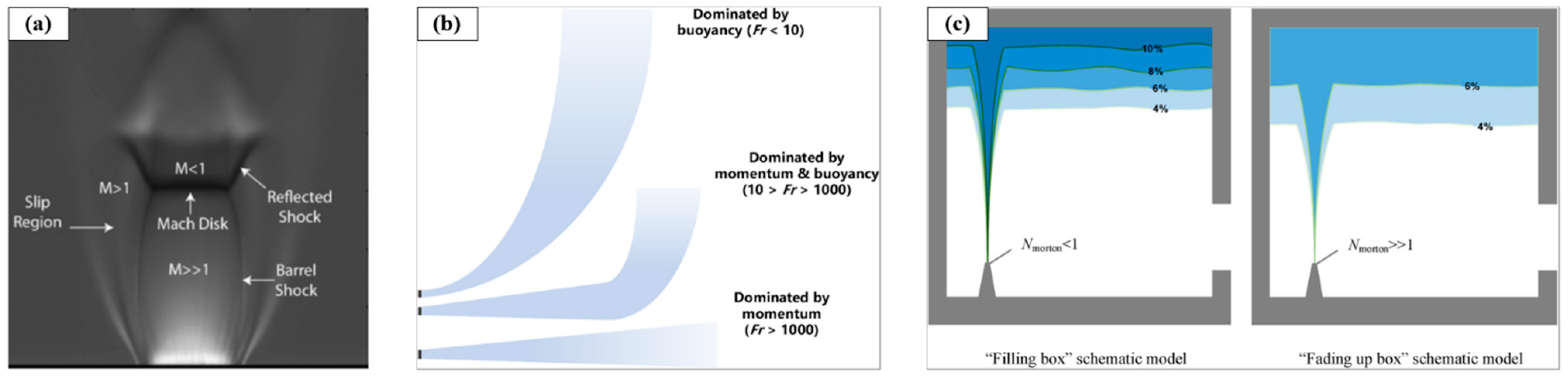
3.1. Hydrogen Leakage and Diffusion

Based on the ratio of pressure between the gas source and the surrounding atmosphere, the leakage jet at the leak outlet can be divided into three flow states [55]: (1) subsonic jet, characterized by the complete expansion of the jet gas at the exit; (2) critical state jet, where the outlet velocity of the jet reaches the local speed of sound; and (3) under-expanded jet, characterized by further expansion and acceleration after the jet enters the surrounding air. The critical pressure ratio can be determined by the following formula:
p c r p a = γ + 1 2 γ γ 1
where p c r is the critical pressure, p a is the external atmospheric pressure, and γ is the adiabatic index. For hydrogen, γ is 1.4, which results in a critical pressure for hydrogen of 0.19 MPa. Currently, the pipeline pressure before pressure reduction in a fuel cell system is greater than 0.19 MPa, and hydrogen storage tanks in commercial hydrogen-powered vehicles are pressurized to either 35 MPa or 70 MPa, which is significantly higher than this value. Similarly, the pressure of gaseous hydrogen storage equipment at hydrogen refueling stations also far exceeds the critical pressure of hydrogen, leading to under-expanded jets in such high-pressure leakage situations.
The characteristics of an under-expanded jet are its intricate shock pattern and non-uniform velocity profile. At the termination point of the under-expanded jet flow, a Mach disk develops, marking the division between the supersonic and subsonic segments of the jet, as shown in Figure 3a. The location and size of the Mach disk depend on factors such as the pressure ratio, the diameter of the nozzle, and its shape [56,57]. A hydrogen subsonic free jet is influenced by air buoyancy and initial momentum, as shown in Figure 3b. The momentum-to-buoyancy ratio is typically described using the exit densimetric Froude number, which is determined by the following calculation [58]:
F r = U exit   g d noz   ρ ρ exit ρ exit  
where Uexit is the flow speed of hydrogen at the outlet, dnoz represents the leak hole diameter, ρ represents the density, and subscripts exit and represent the location of the environment and outlet, respectively. If the Froude number is less than 10, buoyancy primarily controls the behavior of the hydrogen jet. If the Froude number falls between 10 and 1000, the physical movement of the hydrogen flow is influenced by both its initial momentum and its buoyancy, which interact with each other. If the Froude number exceeds 1000, the jet’s movement is predominantly governed by its initial momentum.
If hydrogen leaks into a confined space, the hydrogen–air mixture undergoes two distinct patterns of formation and development, as shown in Figure 3c. The first type is the “filling box model”, which refers to a leakage scenario where the leak occurs at low pressure and low momentum, changing into a plume prior to hitting the ceiling. At the ceiling, due to insufficient mixing, concentration stratification occurs. The second type is the “fading up box model”, which is characterized by a high-pressure leakage mode with significant initial momentum. In this scenario, the hydrogen gas hits the ceiling with some momentum and mixes more thoroughly with the surrounding gas at the ceiling.
With the development of computer technology, the calculation of complex flow through computational fluid dynamics (CFD) simulation has become an important means of studying hydrogen leakage and diffusion. The continuity equation (Equation (3)), momentum equation (Equation (4)), energy equation (Equation (5)), and component transport equation (Equation (6)) are usually used as the governing equations of the computing domain, and the governing equations are discretized and solved by numerical methods such as the finite element method or finite volume method.
ρ t + ρ u x + ρ v y + ρ w z = S m
t ρ v + ρ v v = p + τ ̿ + ρ g + F
v ρ E + p = K e f f T j   h j J ¯ j + τ ̿ e f f v
t ρ Y j + ρ v Y j = J j + R j + S j
where u, v, and w represent the velocity components in the X, Y, and Z directions, respectively (units: m/s); p is the static pressure (units: Pa); τ ̿ is the stress tensor resulting from viscous forces (units: Pa); F is the body force (units: m/s2); E is the total energy of the fluid element (units: J/kg), including internal energy, kinetic energy, and potential energy; Keff is the effective thermal conductivity (units: W/(m·K)); hj is the enthalpy of component j (units: J/kg); Yj is the local mass fraction of component j; and Jj is the diffusion flux of component j caused by concentration gradients and temperature gradients.

3.2. Self-Ignition of High-Pressure Hydrogen Pipeline Release

A study by Kingston University in the UK indicates that nearly 60% of hydrogen combustion and explosion incidents occur without a discernible ignition source [60], generally thought to be due to hydrogen self-ignition. However, there is still significant debate surrounding the mechanism of hydrogen self-ignition, with diffusion ignition theory being widely accepted [61]. When hydrogen under pressure is discharged into a shock tube that holds air, highly turbulent supersonic flow is generated within the pipeline. The areas where air and H2–air mixtures interact with the hydrogen jet experience rapid thermal elevation as a result of the influence of these shock waves. In certain scenarios, this swift heating may initiate spontaneous ignition within the H2–air mixture area, leading to the generation of a highly turbulent self-ignition flame [62,63]. Figure 4 shows the process of spontaneous combustion of hydrogen gas under the action of shock waves in the pipeline.
By utilizing sophisticated experimental techniques such as high-sensitivity detectors, ionic probes, schlieren visualization, and high-speed photographic equipment, researchers have developed a qualitative understanding of the factors influencing self-ignition. The probability of spontaneous ignition rises in proportion to the length of the discharge tube, but this trend diminishes after reaching a specific threshold [65,66]. The role of pipe diameter in determining the chance of self-ignition during the high-pressure release of hydrogen is rather insignificant, with a smaller pipe diameter limiting the impact intensity and thereby inhibiting self-ignition [67]. Compared to extension tubes of rectangular configuration, cylindrical extension tubes require elevated ignition pressure for discharge. Upon an abrupt alteration in the extension tube’s configuration, the threshold pressure for spontaneous ignition of high-pressure hydrogen diminishes. When the extension tube is bent at varying angles, a smaller angle results in a more powerful reflected shock wave. Local contractions, local expansions, sudden contractions, and sudden expansions in the extension tube will significantly raise the chances of hydrogen self-ignition [68].

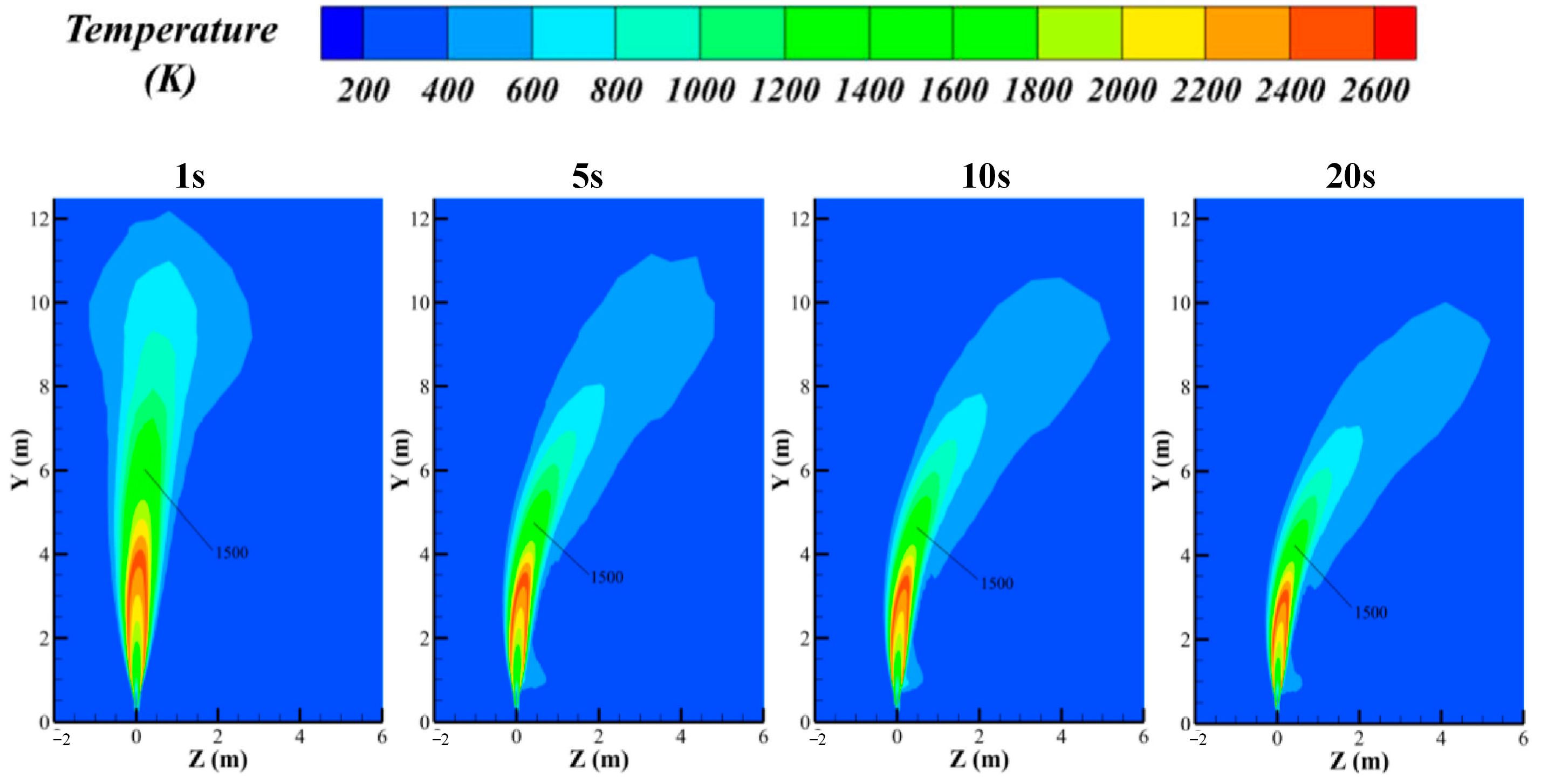
3.3. Hydrogen Jet Flame

When high-pressure hydrogen leakage ignites (due to either an external ignition source or hydrogen self-ignition), it can often result in a jet flame (as shown in Figure 5). In accordance with pertinent rules and norms established by various nations and entities (UN GTR 13 [69], GB/T 35544-2017 [70], JARI S-001 [71]), thermal pressure relief devices (TPRDs) should be installed on the valves of high-pressure hydrogen storage tanks for the purpose of safety protection. Once the temperature surpasses the threshold value (110 °C ± 5 °C), pressurized hydrogen is capable of being swiftly released into the surroundings [72].
The release of pressure from the hydrogen tank eliminates the risk of the tank rupturing, but the jet flame behavior during the release process has attracted more attention from researchers. Zou and colleagues [73] performed a fire test involving a type III hydrogen storage tank that was fitted with a TPRD. The tank had a volume of 48 L and a filling pressure of 70 MPa. The maximum length/width of the jet flame was 4.93 m/1.65 m, demonstrating a pattern of variation and decline over time. The flame length bears a direct ratio to the hydrogen storage pressure and the TPRD diameter [74]. The formula given below enables the calculation of the jet flame’s length [75]:
F r f = u j f s 1.5 ρ j ρ 0.25 Δ T f T g d 0.5
The non-dimensional representation of flame length is given by [75]:
L * = L f f s d j ρ e ρ 1 2 = L f f s d *

3.4. Hydrogen Cloud Explosion

Based on the flame propagation velocity and hydrogen–air mixture composition, the classification of hydrogen explosions encompasses several types: expansion deflagration, mixture deflagration, detonation, and deflagration-to-detonation (DDT) [76]. If a minor hydrogen leak occurs and is sparked by a low-energy ignition source prior to complete mixture, it will result in either a jet flame or a fireball. In the event of a violent hydrogen leak from a hydrogen container, a deflagration will occur, accompanied by large fireballs that generate considerable overpressure. When hydrogen leaks and mixes thoroughly with air to form a flammable mixture without immediate ignition, upon being ignited, it will first deflagrate. With continued flame acceleration, the deflagration may evolve into a detonation, causing a transition from a non-explosive burning state to an explosive detonation [77]. Figure 6 displays the high-speed photographs captured during the experiments, revealing that the detonation flame velocity attained approximately 1980 m per second. At an equivalent hydrogen concentration ratio, the detonation’s peak overpressure was determined to be approximately five times greater than that of a hydrogen deflagration [78].
The explosion load of hydrogen is affected by a range of factors, including the size and inhomogeneity of the hydrogen–air cloud, ignition energy, and ambient temperature and pressure, as well as obstacles. In the case of a small H2–air cloud volume, insufficient hydrogen is present to enable turbulent flame acceleration. Provided that the hydrogen–air cloud possesses a sufficiently large volume, a transition from DDT may take place following ignition. Certain researchers hold the view that inhomogeneity could assist in decreasing the speed of flame spread, thereby lessening the impact of the explosion [79]. The magnitude of the ignition energy directly influences the kind of hydrogen explosion that occurs. It has been discovered that the direct detonation of hydrogen necessitates potent ignition sources, such as high explosives, jet flames, and short circuits in high-voltage capacitors. Conversely, weaker ignition sources, like hot surfaces or sparks, can only result in fire and deflagration, rather than detonation [80]. A mild ignition source initiating deflagration can also result in the transformation of deflagration into detonation, particularly when the hydrogen cloud reaches a considerable size [76]. In an adiabatic and isochoric environment, the blast overpressure exhibits an approximate linear relationship with the initial pressure. Additionally, when the initial pressure remains constant, elevating the initial temperature results in a diminished blast overpressure [80]. The existence of a rigid obstacle leads to enhanced reflection of the blast wave, consequently amplifying the magnitude of the reflected blast overpressure. Experiments have shown that a higher blockage ratio leads to higher peak explosion pressure and flame speed, while simultaneously resulting in a decrease in peak overpressure behind the obstacle [81].

4. Safety Analysis of Hydrogen-Powered Train Scenarios

In the practical application of hydrogen-powered trains, diversity and complexity coexist, accompanied by numerous challenges. To ensure the safety of hydrogen-powered train operations and subsequently promote the widespread adoption of hydrogen energy and the decarbonization of rail transport, it is essential to analyze the compatibility of hydrogen with various scenarios. Based on this, a detailed discussion is conducted on the safety of hydrogen-powered trains in the scenario of electrified railways, tunnels, train garages, and hydrogen refueling stations.

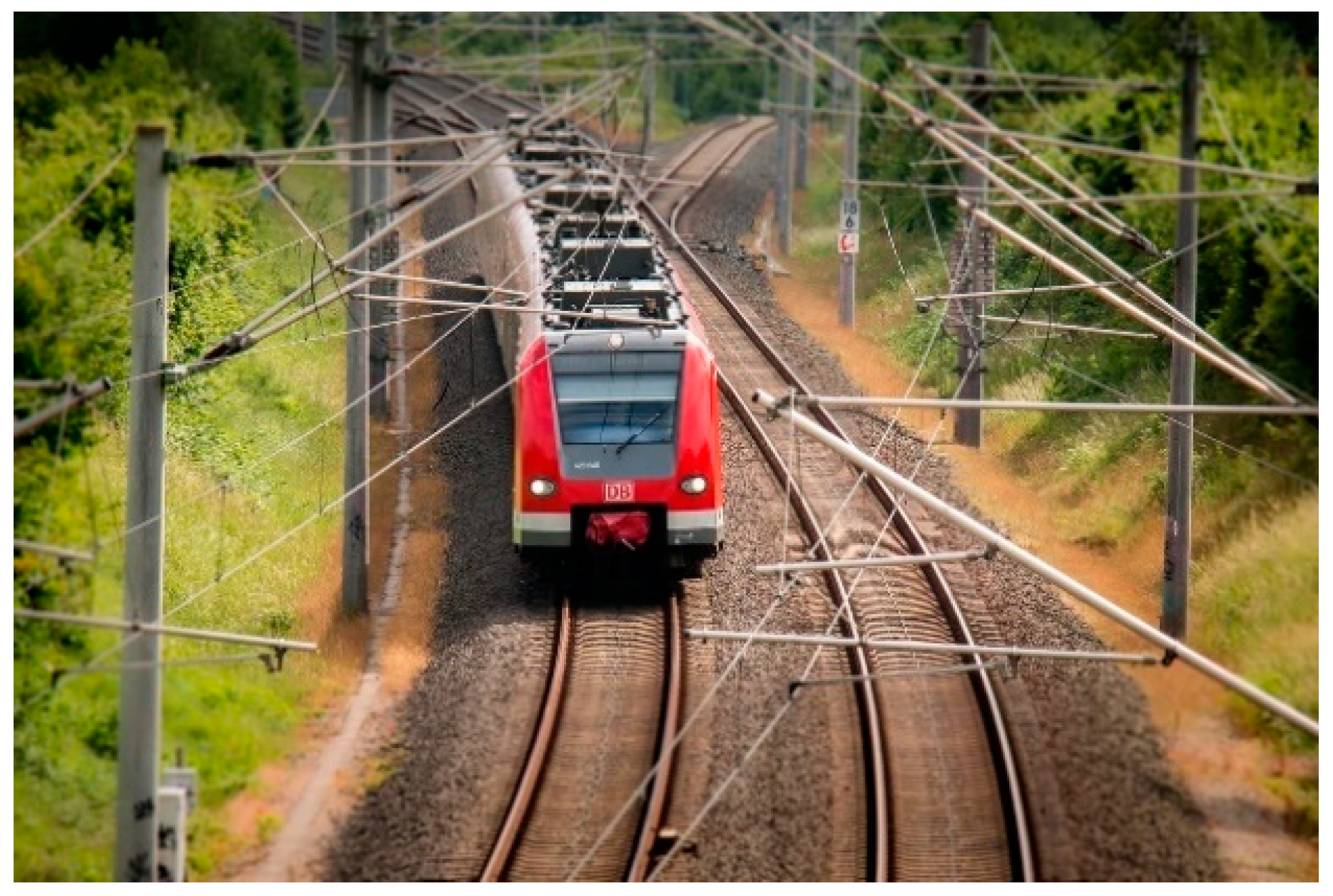
4.1. The Scenario of Electrified Railways

Electrified railways refer to railway systems that continuously supply power to electric locomotives, electric multiple units (EMUs), and other electrically driven trains (Figure 7). They primarily consist of an external power supply system, traction substations, an overhead contact system, return lines, and lighting systems. Traction substations, typically located along the railway line, convert and transmit high-voltage electricity from power plants to the overhead contact line above the railway or to the third rail alongside the track. The overhead contact line provides stable, continuous electric power to EMUs via pantographs, supporting high-speed train operations. Compared to traditional fuel-powered systems, electrified railways offer advantages such as lower energy consumption, higher efficiency, and reduced emissions. They are widely used in high-speed rail and urban transit systems and have become a mainstream construction mode of modern railways and a significant direction for future development [82].
The contact between the overhead contact line and the train’s pantograph is not always stable. Because of vertical shaking, unevenness in the contact wire, disruptions caused by airflow, and imperfections on the contacting surface, there may be short-term “detachment” between the pantograph and the contact network [83,84]. Meanwhile, electric spark and arc are likely to occur between the contact pair, as illustrated in Figure 8a. During the process of switching the contacts on and off, when the surfaces of the two contacts come very close together (leaving just a minute space between), the voltage present can cause electrical breakdown between them, resulting in arcing [85,86]. The intense heat generated by arc discharge easily produces molten pool pits on the surface of the contact wire and also causes ablation on the surface of the carbon slider. An electric arc is commonly segmented into the cathode region, the arc’s main body, and the anode region, as shown in Figure 8b. Additionally, contaminants adhering to the surface of high-voltage electrical insulation may dissolve into water under humid conditions, resulting in the formation of a conductive layer on the insulator surface. This considerably lowers the degree of insulation, making it susceptible to a phenomenon known as contamination flashover discharge (Figure 8c).
Given the high prevalence of electrified railways in modern railway systems, the application of hydrogen-powered trains on electrified lines is expected to become increasingly common. Although hydrogen-powered trains do not require pantographs or a power supply from the overhead contact line, this poses challenges for electrified railways in addressing hydrogen safety. Hydrogen has a low density and strong diffusivity. In case of a hydrogen leakage, it is highly likely to spread rapidly to the overhead pantograph area. If coupled with environmental winds and aerodynamic disturbances caused by passing trains, the flow direction of hydrogen becomes even more complex. Kim et al. [88] experimentally observed the evolution of the flammable zone during liquid hydrogen leakage under different atmospheric conditions, and they suggested that a wind speed of 2 m/s or higher can promote the dilution of hydrogen clouds. The temporal and spatial evolution of hydrogen leakage and diffusion under the effect of ambient wind can draw upon relevant vehicle research for reference [89,90]. Once a contamination flashover occurs or a neighboring train’s pantograph–catenary arc is generated, the hydrogen can be easily ignited. According to the Chinese national standard GB/T 29729-2022 [91], the minimum ignition energy for hydrogen in air is 0.017 mJ at a hydrogen concentration of 22~26%, with an ignition temperature of 858 K. It is evident that both the ignition energy and the temperature are sufficient to meet the conditions for igniting hydrogen. In case of an incident, upward-released hydrogen could ignite and sustain a jet flame that would continuously burn the pantograph, creating a high-voltage hazard and potentially leading to a complete shutdown of the railway line. In a study by Li et al. [92], the flame length reached 3.48 m upon the occurrence of a leak in a hydrogen storage tank, which was under a pressure of 30 MPa, through a 2 mm diameter hole, and the ambient wind altered the flame morphology (Figure 9). If the hydrogen tank is mounted on top of a train (as is common on most hydrogen-powered trains), it is apparent that the flame has reached the height of the pantograph.
In summary, hydrogen-powered trains must consider operating alongside EMUs on electrified lines, as constructing a separate line specifically for hydrogen-powered trains is not feasible from a cost perspective. Although it is unlikely for leaked hydrogen to explode in an open environment, the hazard of jet flames must be guarded against. On electrified lines, arcs, static electricity, and sparks are frequent. In extreme cases, a large leak of hydrogen can easily be ignited to form a jet flame, causing damage to the pantograph and overhead lines. Under the influence of environmental crosswinds, this may also endanger adjacent trains. Unfortunately, there is limited direct and quantitative analysis of hydrogen leakage in the environment of electrified pantograph and overhead lines. Ensuring the safety of hydrogen-powered trains on electrified railways remains a primary challenge for expanding commercial operation. The cost of monitoring hydrogen leakage from a hydrogen train from the pantograph position is large because the line is extremely long. Given that extensive railway lines are located in open outdoor environments and the hydrogen will quickly dilute upward, it is more important to keep the pantograph insulated without sparks [93,94]. The German ICE high-speed railway employs a real-time monitoring system and active arc-suppression devices, which are used to rapidly disconnect short-circuit currents and prevent arc damage. The pantograph of a railway should possess strong fire resistance capabilities through material innovation, structural optimization, and rigorous testing, enabling it to withstand fires ignited by accidental hydrogen cylinder leaks. As mentioned earlier, flames ignited by hydrogen cylinder TPRD release can easily reach the height of the pantograph [92]. In railway emergency response plans, there is an urgent need to strengthen measures for dealing with faults in hydrogen-powered trains. For instance, in the event of a hydrogen leak, an emergency power shutoff should be implemented for the pantograph and catenary system located on top of the train, adjacent train lines should be prevented from approaching, and personnel evacuation should be guided.

4.2. The Scenario of Tunnels

The most dangerous operational scenario for hydrogen-powered trains is in tunnel areas with restricted space and low-hanging ceilings, as shown in Figure 10a. Depending on their location, tunnels can be categorized into mountain tunnels, underwater tunnels, or urban tunnels. Although ventilation equipment is typically installed, the space still qualifies as a confined environment where the diffusion of hydrogen flow is severely restricted (Figure 10b). It is generally acknowledged that unintentional hydrogen release in an exposed outdoor setting will dissipate rapidly, thus posing no significant hydrogen-related risks. A greater likelihood of a hydrogen hazard arises when hydrogen is unintentionally released in tunnels. According to the hydrogen hazard chain, if hydrogen is not ignited immediately but forms a hydrogen–air flammable cloud at the top of the tunnel, an explosion will be triggered once it is ignited. Another possible situation is the formation of a jet flame in the tunnel if hydrogen catches fire shortly after the leakage occurs. Compared with the explosion scenario, a jet flame hazard poses little risk to the passengers and facilities and is controllable [95]. But there is still a need to be vigilant against the threat of toxic smoke generated by the combustion.
The research on hydrogen safety in tunnels for trains can draw heavily from the studies on hydrogen safety in tunnels for vehicles, as the demonstration of hydrogen fuel cell vehicles (HFCVs) precedes that of hydrogen-powered trains. Yan and his colleagues [97] modeled the escape of hydrogen from a hydrogen-powered bus in a bidirectional “concave”-shaped tunnel. They found that in the riverbed section, reduced leakage areas or increased mass flow rates led to greater volumes and higher mass fractions of leakage gas clouds within a tunnel. Houf et al. [98] performed an integrated experimental and modeling analysis to investigate releases from an HFCV within a tunnel environment. Their results show that both the predicted and measured hydrogen mole fractions rose sharply from 0 to roughly 0.4 within the first second after the release began, at a distance of 1.5 m along the tunnel axis from the vehicle’s center. Researchers are particularly concerned about the risk of jet flames caused by ignition or spontaneous combustion when hydrogen is rapidly released from the bottle. Xie et al. [99] hold the view that there exist significant disparities between pool fires fueled by traditional fossil fuels and jet fires emanating from HFCVs. In the case of fires from HFCVs, a rapid hydrogen jet, possessing considerable inertial force, can propel the heated smoke flows back towards the ground, posing a greater threat to passengers compared to pool fires. Both longitudinal and lateral ventilation methods have been proven to be effective in controlling tunnel temperature increase and minimizing flame damage [100]. Groethe et al. [78] and Sato et al. [101] conducted a series of hydrogen deflagration experiments in a 1/5-scale highway tunnel model, as shown in Figure 11A. The study found that a 30% (1 kg) hydrogen mixture produced a notable pressure pulse of approximately 150 kPa. Li et al. [102] examined a tunnel accident involving HFCVs using the parallel CFD code GASFLOW-MPI. Their study encompassed the release, dispersion, jet fire, and detonation of hydrogen, providing a comprehensive approach to addressing the safety concerns of HFCVs in tunnel environments, as shown in Figure 11B,C. S. Kudriakov et al. [103] conducted hydrogen storage tank rupture experiments in a full-scale highway tunnel in France, utilizing PicoCoulomB sensors and pressure sensors to characterize the propagation patterns of the blast wave. Experimental data revealed that the mechanical energy from the pressurized gas (70~95%) contributes significantly to the intensity of the blast wave. Images captured by high-speed cameras showed that the fireball resulting from the explosion of a 78 L hydrogen cylinder pressurized at 520 bar could completely fill a tunnel cross-section.
Although there is no essential difference between hydrogen safety accidents in automobile tunnels and those in train tunnels, the safety of hydrogen-powered trains in tunnels deserves significantly more attention and is clearly under-researched in academia. In comparison to hydrogen fuel cell vehicles, the hydrogen storage system in trains contains more hydrogen cylinders and stores larger amounts of hydrogen. In particular, some countries are preparing to use liquid hydrogen as a fuel source, such as South Korea, which is developing liquid hydrogen locomotives. The potential leakage of a large amount of hydrogen, coupled with the low-hanging catenary and the complex electrified environment inside tunnels, increases the probability and risk of accidents occurring within train tunnels. To address hydrogen safety incidents, tunnels should be equipped with a comprehensive hydrogen leak detection and alarm system, and the electrical equipment inside the tunnels should feature explosion-proof design. If the hydrogen cannot be cut off from the hydrogen supply source, guidance through broadcasting should be provided to evacuate personnel along escape routes, and the use of open flames or electronic devices should be avoided (to prevent sparks from igniting hydrogen). When a hydrogen leak occurs, active ventilation should be promptly initiated, as the effectiveness of ventilation and dilution within tunnels has been extensively verified [97,104]. After confirming that the hydrogen concentration has dropped to a safe range, professionals should enter to conduct inspections.

4.3. The Scenario of a Train Station and Refueling Station

The openness of a train station is stronger than that of a tunnel but weaker than that of an open-air environment, as shown in Figure 12. Due to the enclosed design at the top, the upward flow and dispersion of hydrogen are restricted, which can lead to hydrogen accumulation. Additionally, a train station has distinct electrified features, including overhead power lines, pantographs, and lighting fixtures, resulting in hydrogen being easily ignited. As a location for passenger boarding and alighting, the train station is densely populated with a large volume of pedestrian traffic. Consequently, in the event of hydrogen leakage, a fire, or an explosion, there is a risk of widespread transportation disruptions, casualties, and economic losses, with particularly severe social repercussions.
At present, the station is not yet ready to accommodate hydrogen-powered trains. To ensure safety, it is essential to equip the train station with highly sensitive hydrogen detection devices, use hydrogen-resistant materials, implement explosion-proof electrical appliances, and design an efficient ventilation system to prevent hydrogen accumulation. In addition, a comprehensive emergency response plan must be established, with regular drills conducted to enhance the overall preparedness for unforeseen events.
The safety issues in the scenario of train hydrogen fueling originate from the hydrogen refueling station itself, rather than from the train. The hydrogen storage capacity at a hydrogen refueling station is enormous, with storage pressures reaching up to 100 MPa. In such a high-pressure environment, frequent use of the fueling system can easily lead to hydrogen leakage accidents. Academia has conducted extensive research on hydrogen leaks in hydrogen refueling stations. Wang et al. [105] investigated hydrogen leaks from trucks at hydrogen refueling stations, discovering that the bulk of the flammable material accumulates in a layer of half a meter beneath the ceiling, and diminishing within a single minute (Figure 13A). Although thermal radiation poses minimal risk to personnel on the ground, the overpressure could likely cause structural failure, potentially leading to indirect fatalities. Liu et al. [106] conducted an in-depth study on hydrogen leaks and dispersion in different areas of refueling stations, examining the relationship between delayed ignition times and explosion effects following an accidental hydrogen release (Figure 13B). The study revealed that wind speed has a markedly different impact on the probability of hydrogen fires in various station zones. Under low wind speed conditions, the combustible cloud expands in the areas in front of the trailer and in outer regions, where a spherical cloud structure forms at the forefront of the outer region, significantly increasing the likelihood of hydrogen explosions. Additionally, factors such as the jet angle of hydrogen release [107] and ventilation systems [108] greatly affect the concentration distribution of leaked hydrogen.
It is necessary for train stations and refueling stations to install hydrogen sensors at key locations (such as hydrogen storage areas, hydrogen pipeline links, etc.) combined with online real-time data acquisition and manual inspection to improve monitoring and early warning. Once a hydrogen leak is detected, the hydrogen supply valve must be quickly closed to cut off the gas source and prevent further leakage. At the same time, evacuation procedures should be immediately initiated to guide passengers and staff to evacuate to a safe area. Ventilation is then activated to accelerate hydrogen diffusion and discharge to reduce the risk of explosion. Professional firefighting teams should be on standby at stations and hydrogen refueling stations to ensure prompt response to fires or other secondary disasters. The explosion at the Sandvika hydrogen refueling station in Norway in 2019 was caused by faulty bolt assembly. It is very important to strengthen the training of staff involved in the operation of sealed containers and pipelines.

4.4. The Scenario of Garages

After completing their operations, trains typically enter the garage (Figure 14a) for necessary maintenance, which includes tasks such as flaw detection, cleaning, maintenance, reinforcement of fasteners, and equipment calibration. Currently, due to the high cost of building facilities for hydrogen-powered trains, these trains often share existing garage facilities with EMUs. Since the garage is relatively enclosed, with inadequate ventilation, hydrogen tends to accumulate at the top, leading to an increased risk of fires and explosions. Furthermore, the large number of trains and electrical circuits within the garage amplify the potential severity of the resulting hazards.
The space in a train garage is similar to that of a large automobile garage, and the principles related to hydrogen leakage in automobile garages can be applied to train garages. Huang et al. [109] conducted hydrogen diffusion modeling in large underground parking garages and found that, under the influence of buoyancy, hydrogen clouds tend to flow upward toward the garage ceiling, spreading along the ceiling to form a progressively thickening hydrogen–air mixture layer (Figure 14b). Choi et al. [110] studied the ventilation system within a garage and discovered that installing fans had a significant impact on reducing hydrogen concentration. As the airflow increased, the volume fraction of the flammable zone decreased more rapidly. This indicates that fans enhanced the mixing near the flammable area, effectively delaying its spread and reducing the likelihood of an accident. Li et al. [111] researched the impact of ceiling beams on hydrogen flow within the garage, finding that as the beam height increased, hydrogen flow was further obstructed, resulting in an expansion of the combustible zone. To verify the accuracy of CFD tools and modeling methods in predicting short- and long-term mixing and distribution of hydrogen release in a limited space, Venetsanos et al. [112] released hydrogen at a rate of 1 g/s in a garage-like space of 7.2 m × 3.78 m × 2.88 m and used 16 hydrogen sensors to collect data at key locations. Compared to the experimental data, the simulation models tended to overestimate the concentrations when applying the standard k–ε model. In the hydrogen diffusion phase, the models tended to overestimate turbulent mixing, and a quasi-homogeneous layer of hydrogen near the ceiling was not predicted. Zhao et al. [113] developed a hydrogen leak detection system using data obtained from a scaled model of a garage, combining machine learning algorithms to predict the leak location with an accuracy of 87.5%. This system aids personnel in identifying relatively small leak zones and locating the leaking vehicle.
Compared to automobile garages, train garages are significantly larger in volume, with more electrical components, and there is a lack of in-depth studies on hydrogen diffusion simulations and the impact of explosive damage. For a train with a lithium–hydrogen hybrid power system, the hydrogen can be fully released before entering the garage to ensure safety. But we have to consider the situation where it is purely hydrogen-driven and the hydrogen system requires debugging within the garage setting. Therefore, it is crucial to enhance hydrogen leakage simulation and experimental research based on train garage scenarios. This can be achieved by identifying potential leakage paths, diffusion, and accumulation processes, which will guide the placement of sensors and assess the risks of fire and explosion. Such research will help optimize the garage’s risk management system, improve the safety standards for hydrogen-powered train storage and maintenance, and ensure a scientific response to hydrogen leakage accidents.
Hydrogen safety measures in garages need to be comprehensively managed from design, equipment, monitoring, emergency response, and other aspects. An efficient ventilation system should be installed to ensure air circulation in the garage and prevent hydrogen buildup. The vent should be set at the top of the garage, because hydrogen is lighter than air and easily diffuses upward. The garage is divided into different functional areas, such as a parking area, a hydrogen storage area, a maintenance area, etc., and physical isolation measures are set up to prevent hydrogen leakage from spreading to other areas. Explosion-proof electrical equipment and lighting facilities should be used to avoid a hydrogen explosion caused by an electrical spark. Fixed hydrogen sensors should be installed within the garage to continuously monitor hydrogen concentrations. The sensors should cover critical areas of the garage (such as parking spaces, hydrogen storage areas, and the vicinity of ventilation outlets) and possess the ability to deduce the location of leakage sources [113]. Upon detection of a hydrogen leak, an audible and visual alarm should be immediately triggered and evacuation procedures should be initiated to guide personnel to safely evacuate to a secure area. Simultaneously, the hydrogen supply valve should be swiftly shut off and the ventilation equipment activated. In addition, training on hydrogen safety knowledge and emergency handling should be provided to garage staff to ensure they are familiar with the characteristics of hydrogen and emergency response procedures.
Studies on hydrogen leakage under different scenarios are summarized and compared, as shown in Table 2.

5. Conclusions

This paper analyzes the risks associated with hydrogen leakage and its application scenarios in rail transport from a safety perspective, focusing on hydrogen-powered trains. First, it reviews the current demonstration operations of hydrogen-powered trains from various countries. Next, the paper systematically discusses the hazard chain of hydrogen leakage, including leakage, diffusion, self-ignition, jet flame, and explosion processes. Finally, combining scene characteristics with the properties of hydrogen, a detailed safety analysis is conducted on the application scenarios of hydrogen-powered trains. Hydrogen-powered trains present new challenges to existing train scenarios, and currently, these environments are not yet ready for large-scale commercial operation of hydrogen-powered trains due to the insufficient safeguards against potential hydrogen leak hazards, highlighting the importance and urgency of research in hydrogen-powered rail transport safety.

Author Contributions

Conceptualization, L.X. and Y.L.; methodology, W.Z.; formal analysis, Y.L.; investigation, W.Z.; resources, L.X.; writing—original draft preparation, X.J.; writing—review and editing, X.J.; supervision, T.M.; project administration, X.J.; funding acquisition, T.M. All authors have read and agreed to the published version of the manuscript.

Funding

This work is supported by the National Key R&D Program of China (No. 2022YFE0208000).

Data Availability Statement

Data are contained within the article.

Conflicts of Interest

The authors declare no conflicts of interest.

Abbreviations

The following abbreviations are used in this manuscript:
BOGBoil-off gas
CFDComputational fluid dynamics
DDTDeflagration to detonation
EMUsElectric multiple units
EISElectrochemical impedance spectroscopy
GDLGas diffusion layer
HFCVsHydrogen fuel cell vehicles
LBMLattice Boltzmann method
LCCLife cycle costing
LOHCsLiquid organic hydrogen carriers
MOFsMetal–organic frameworks
MPLMicroporous layer
PHMPrognosis and health management
PEMFCProton exchange membrane fuel cell
SOHState of health
TPRDsThermal pressure relief devices

References

  1. Adu, D.; Jianguo, D.; Asomani, S.N.; Abbey, A. Energy generation and carbon dioxide emission-The role of renewable energy for green development. Energy Rep. 2024, 12, 1420–1430. [Google Scholar] [CrossRef]
  2. Fan, J.Q.; Meng, X.S.; Tian, J.X.; Xing, C.H.; Wang, C.; Wood, J. A review of transportation carbon emissions research using bibliometric analyses. J. Traffic Transp. Eng. 2023, 10, 878–899. [Google Scholar] [CrossRef]
  3. Anand, C.; Chandraja, B.; Nithiya, P.; Akshaya, M.; Tamizhdurai, P.; Shoba, G.; Subramani, A.; Kumaran, R.; Yadav, K.K.; Gacem, A.; et al. Green hydrogen for a sustainable future: A review of production methods, innovations, and applications. Int. J. Hydrogen Energy 2025, 111, 319–341. [Google Scholar] [CrossRef]
  4. Sebbahi, S.; Assila, A.; Alaoui Belghiti, A.; Laasri, S.; Kaya, S.; Hlil, E.K.; Rachidi, S.; Hajjaji, A. A comprehensive review of recent advances in alkaline water electrolysis for hydrogen production. Int. J. Hydrogen Energy 2024, 82, 583–599. [Google Scholar] [CrossRef]
  5. Zhang, W.W.; Li, Y.F.; Li, H.F.; Liu, S.Y.; Zhang, J.Y.; Kong, Y. Systematic review of life cycle assessments on carbon emissions in the transportation system. Environ. Impact Assess. 2024, 109, 107618. [Google Scholar] [CrossRef]
  6. Ahmad, S.; Ullah, A.; Samreen, A.; Qasim, M.; Nawaz, K.; Ahmad, W.; Alnaser, A.; Kannan, A.M.; Egilmez, M. Hydrogen production, storage, transportation and utilization for energy sector: A current status review. J. Energy Storage 2024, 101, 113733. [Google Scholar]
  7. Agyekum, E.B.; Odoi-Yorke, F.; Abbey, A.A.; Ayetor, G.K. A review of the trends, evolution, and future research prospects of hydrogen fuel cells—A focus on vehicles. Int. J. Hydrogen Energy 2024, 72, 918–939. [Google Scholar] [CrossRef]
  8. Shi, Y.; Qiu, Z.H.; Snyder, S.W.; Wang, Y.X. A perspective on broad deployment of hydrogen-fueled vehicles for ground freight transportation with a comparison to electric vehicles. Energy Strategy Rev. 2024, 56, 101565. [Google Scholar]
  9. Yamchi, H.B.; Kandidayeni, M.; Kelouwani, S.; Boulon, L. Constrained exploration method for optimal energy management in hybrid multi-stack fuel cell vehicles. Energy Convers. Manag. 2024, 316, 118841. [Google Scholar] [CrossRef]
  10. Pu, J.; Xie, Q.; Li, J.; Zhao, Z.; Lai, J.; Li, K.; Zhou, F. Research on the technical scheme of multi-stack common rail fuel cell engine based on the demand of commercial vehicle. Energy Ai 2024, 16, 100353. [Google Scholar] [CrossRef]
  11. Tang, X.; Shi, L.; Li, M.; Xu, S.; Sun, C. Health State Estimation and Long-Term Durability Prediction for Vehicular PEM Fuel Cell Stacks Under Dynamic Operational Conditions. IEEE Trans. Power Electron. 2025, 40, 4498–4509. [Google Scholar]
  12. Wallnöfer-Ogris, E.; Poimer, F.; Köll, R.; Macherhammer, M.-G.; Trattner, A. Main degradation mechanisms of polymer electrolyte membrane fuel cell stacks—Mechanisms, influencing factors, consequences, and mitigation strategies. Int. J. Hydrogen Energy 2024, 50, 1159–1182. [Google Scholar]
  13. Zhao, L.; Hong, J.; Yuan, H.; Ming, P.; Wei, X.; Dai, H. Dynamic inconsistent analysis and diagnosis of abnormal cells within a high-power fuel cell stack. Electrochim. Acta 2023, 464, 142897. [Google Scholar]
  14. Zhao, L.; Yuan, H.; Xie, J.; Jiang, S.; Wei, X.; Tang, W.; Ming, P.; Dai, H. Inconsistency evaluation of vehicle-oriented fuel cell stacks based on electrochemical impedance under dynamic operating conditions. Energy 2023, 265, 126162. [Google Scholar]
  15. Meng, X.; Sun, C.; Mei, J.; Tang, X.; Hasanien, H.M.; Jiang, J.; Fan, F.; Song, K. Fuel cell life prediction considering the recovery phenomenon of reversible voltage loss. J Power Sources 2025, 625, 235634. [Google Scholar] [CrossRef]
  16. Hua, Z.; Zheng, Z.; Pahon, E.; Péra, M.-C.; Gao, F. Remaining useful life prediction of PEMFC systems under dynamic operating conditions. Energy Convers Manag. 2021, 231, 113825. [Google Scholar]
  17. Pourrahmani, H.; Van Herle, J. Water management of the proton exchange membrane fuel cells: Optimizing the effect of microstructural properties on the gas diffusion layer liquid removal. Energy 2022, 256, 124712. [Google Scholar]
  18. Chen, H.; Zhang, R.; Xia, Z.; Weng, Q.; Zhang, T.; Pei, P. Experimental investigation on PEM fuel cell flooding mitigation under heavy loading condition. Appl. Energy 2023, 349, 121632. [Google Scholar] [CrossRef]
  19. Yan, S.; Yang, M.; Sun, C.; Xu, S. Liquid Water Characteristics in the Compressed Gradient Porosity Gas Diffusion Layer of Proton Exchange Membrane Fuel Cells Using the Lattice Boltzmann Method. Energies 2023, 16, 6010. [Google Scholar] [CrossRef]
  20. Baz, F.B.; Elzohary, R.M.; Osman, S.; Marzouk, S.A.; Ahmed, M. A review of water management methods in proton exchange membrane fuel cells. Energy Convers Manag. 2024, 302, 118150. [Google Scholar] [CrossRef]
  21. Gao, Z.; Lang, J.T.; Wei, F.; Iskandarani, B.; Qi, Y.; Secanell, M.; Su, J.; Guo, L.; Zenyuk, I.V.; Morimoto, Y. A design of gas diffusion media for polymer electrolyte membrane fuel cell: Characterization and water management investigation. J. Power Sources 2024, 606, 234507. [Google Scholar]
  22. Ji, Z.X.; Miao, X.Y. Overall scheme design of a closed solid oxide fuel cell hybrid engine for ships. Energy Convers Manag. 2024, 314, 118682. [Google Scholar]
  23. Ding, D.N.; Wu, X.Y. Hydrogen fuel cell electric trains: Technologies, current status, and future. Appl. Energy Combust. Sci. 2024, 17, 100255. [Google Scholar] [CrossRef]
  24. Kapetanović, M.; Núñez, A.; van Oort, N.; Goverde, R.M.P. Analysis of hydrogen-powered propulsion system alternatives for diesel-electric regional trains. J. Rail Transp. Plan. Manag. 2022, 23, 100338. [Google Scholar]
  25. Yang, F.; Wang, T.; Deng, X.; Dang, J.; Huang, Z.; Hu, S.; Li, Y.; Ouyang, M. Review on hydrogen safety issues: Incident statistics, hydrogen diffusion, and detonation process. Int. J Hydrogen Energy 2021, 46, 31467–31488. [Google Scholar]
  26. Sun, Y.; Anwar, M.; Hassan, N.M.S.; Spiryagin, M.; Cole, C. A review of hydrogen technologies and engineering solutions for railway vehicle design and operations. Railway Eng. Sci. 2021, 29, 212–232. [Google Scholar]
  27. Chen, W.; Peng, F.; Liu, Z.; Li, Q.; Dai, C. System integration of China’s first PEMFC locomotive. J. Mod. Transp. 2013, 21, 163–168. [Google Scholar]
  28. Peng, F.; Chen, W.; Liu, Z.; Li, Q.; Dai, C. System integration of China’s first proton exchange membrane fuel cell locomotive. Int. J. Hydrogen Energy 2014, 39, 13886–13893. [Google Scholar]
  29. China produces first hydrogen fuel cell tram, with Ballard unit. Fuel Cells Bulletin 2015, 2015, 5.
  30. Mining Locomotive Runs on Hydrogen. Available online: https://www.sandia.gov/labnews/2002/05/03/key05-03-02-storieslocomotive/ (accessed on 11 March 2025).
  31. A Forerunner to the Current Interest in Hydrogen Propulsion Provided the First Test of the Concept. Available online: https://www.trains.com/trn/railroads/locomotives/bnsfs-first-hydrogen-locomotive/ (accessed on 11 March 2025).
  32. Stadler hydrogen fuel cell train for California. Fuel Cells Bulletin 2019, 2019, 1. [CrossRef]
  33. Stadler Presents FLIRT H2 Hydrogen Train for San Bernardino. Available online: https://railway-news.com/stadler-presents-flirt-h2-hydrogen-train-for-san-bernardino/ (accessed on 11 March 2025).
  34. Coradia iLint fuel cell train approved for commercial operation on German railways. Fuel Cells Bulletin 2018, 2018, 6–7. [CrossRef]
  35. HydroFLEX train in first UK mainline trial. Fuel Cells Bulletin 2020, 2020, 5. [CrossRef]
  36. Wurster, R. Fuels—Hydrogen—Hydrogen Storage|Regulations, Codes, and Standards. In Encyclopedia of Electrochemical Power Sources, 2nd ed.; Garche, J., Ed.; Elsevier: Oxford, UK, 2025; pp. 346–359. [Google Scholar]
  37. Moretto, P.; Quong, S. Chapter 7—Legal requirements, technical regulations, codes, and standards for hydrogen safety. In Hydrogen Safety for Energy Applications; Kotchourko, A., Jordan, T., Eds.; Butterworth-Heinemann: Oxford, UK, 2022; pp. 345–396. [Google Scholar]
  38. Ma, X.; Li, B.; Han, B.; Liu, Y.; Song, C. Safety discharge strategies of vehicle-mounted type III high-pressure hydrogen storage tanks under fire scenarios. Int. J. Hydrogen Energy 2024, 93, 1227–1239. [Google Scholar] [CrossRef]
  39. Offer, G.J.; Howey, D.; Contestabile, M.; Clague, R.; Brandon, N.P. Comparative analysis of battery electric, hydrogen fuel cell and hybrid vehicles in a future sustainable road transport system. Energy Policy 2010, 38, 24–29. [Google Scholar] [CrossRef]
  40. Horvath, S.; Fasihi, M.; Breyer, C. Techno-economic analysis of a decarbonized shipping sector: Technology suggestions for a fleet in 2030 and 2040. Energy Convers Manag. 2018, 164, 230–241. [Google Scholar] [CrossRef]
  41. Correa, L.; Razi, F.; Sadiq, R.; Hewage, K. Life cycle costing analysis of a retrofitted hydrogen-powered locomotive: Canadian context. Transp. Res. Part D Transp. Environ. 2024, 133, 104295. [Google Scholar] [CrossRef]
  42. Li, H.; Cao, X.; Liu, Y.; Shao, Y.; Nan, Z.; Teng, L.; Peng, W.; Bian, J. Safety of hydrogen storage and transportation: An overview on mechanisms, techniques, and challenges. Energy Rep. 2022, 8, 6258–6269. [Google Scholar] [CrossRef]
  43. Ikeuba, A.I.; Sonde, C.U.; Charlie, D.; Usibe, B.E.; Raimi, M.; Obike, A.I.; Magu, T.O. A review on exploring the potential of liquid hydrogen as a fuel for a sustainable future. Sustain. Chem. One World 2024, 3, 100022. [Google Scholar] [CrossRef]
  44. Berstad, D.O.; Stang, J.H.; Nekså, P. Large-scale hydrogen liquefier utilising mixed-refrigerant pre-cooling. Int. J. Hydrogen Energy 2010, 35, 4512–4523. [Google Scholar] [CrossRef]
  45. Agyekum, E.B.; Nutakor, C.; Khan, T.; Adegboye, O.R.; Odoi-Yorke, F.; Okonkwo, P.C. Analyzing the research trends in the direction of hydrogen storage—A look into the past, present and future for the various technologies. Int. J. Hydrogen Energy 2024, 74, 259–275. [Google Scholar] [CrossRef]
  46. Ma, Y.; Li, Y.; Zhu, K.; Wang, Y.; Wang, L.; Tan, H. Investigation on no-vent filling process of liquid hydrogen tank under microgravity condition. Int. J. Hydrogen Energy 2017, 42, 8264–8277. [Google Scholar] [CrossRef]
  47. Wang, J.; Alkhaledi, A.N.; Hughes, T.J.; Webley, P.A. Technoeconomic investigation of optimal storage pressure and boil-off gas utilisation in large liquid hydrogen carriers. Appl. Energy 2025, 384, 125356. [Google Scholar] [CrossRef]
  48. Choi, M.; Jung, W.; Ji, S.; Lee, J. Optimization and analysis of reliquefaction system utilizing hydrogen as refrigerant for liquid hydrogen carriers. Appl. Energy 2025, 384, 125490. [Google Scholar] [CrossRef]
  49. Morales-Ospino, R.; Celzard, A.; Fierro, V. Strategies to recover and minimize boil-off losses during liquid hydrogen storage. Renew. Sustain. Energy Rev. 2023, 182, 113360. [Google Scholar] [CrossRef]
  50. Fernández, A.; Arzac, G.M.; Vogt, U.F.; Hosoglu, F.; Borgschulte, A.; Jiménez de Haro, M.C.; Montes, O.; Züttel, A. Investigation of a Pt containing washcoat on SiC foam for hydrogen combustion applications. Appl. Catal. B Environ. 2016, 180, 336–343. [Google Scholar] [CrossRef]
  51. Arzac, G.M.; Montes, O.; Fernández, A. Pt-impregnated catalysts on powdery SiC and other commercial supports for the combustion of hydrogen under oxidant conditions. Appl. Catal. B Environ. 2017, 201, 391–399. [Google Scholar] [CrossRef]
  52. Ikeuba, A.I. TOF-SIMS and AFM analysis of pH effect on the interfacial films on η-phase in aqueous salt solutions. Appl. Surf. Sci. Adv. 2023, 15, 100410. [Google Scholar]
  53. Munyentwali, A.; Tan, K.C.; He, T. Advancements in the development of liquid organic hydrogen carrier systems and their applications in the hydrogen economy. Prog. Nat. Sci. Mater. Int. 2024, 34, 825–839. [Google Scholar] [CrossRef]
  54. Ikeuba, A.I.; Zhang, B.; Wang, J.; Han, E.H.; Ke, W.; Okafor, P.C. SVET and SIET study of galvanic corrosion of Al/MgZn2 in aqueous solutions at different pH. J. Electrochem. Soc. 2018, 165, C180–C194. [Google Scholar] [CrossRef]
  55. Deng, J.; Fan, Y.; Wang, C.; Yang, N. Advances in hydrogen leakage jets for hydrogen storage systems. Int. J. Hydrogen Energy 2024, 93, 585–606. [Google Scholar] [CrossRef]
  56. Han, S.H.; Chang, D.; Kim, J.S. Experimental investigation of highly pressurized hydrogen release through a small hole. Int. J. Hydrogen Energy 2014, 39, 9552–9561. [Google Scholar]
  57. Stewart, J.R. CFD modelling of underexpanded hydrogen jets exiting rectangular shaped openings. Process Saf. Environ. 2020, 139, 283–296. [Google Scholar]
  58. Schefer, R.W.; Houf, W.G.; Williams, T.C. Investigation of small-scale unintended releases of hydrogen: Momentum-dominated regime. Int. J. Hydrogen Energy 2008, 33, 6373–6384. [Google Scholar]
  59. Ruggles, A.J.; Ekoto, I.W. Ignitability and mixing of underexpanded hydrogen jets. Int. J. Hydrogen Energy 2012, 37, 17549–17560. [Google Scholar]
  60. Xu, B.P.; Wen, J.X.; Dembele, S.; Tam, V.H.Y.; Hawksworth, S.J. The effect of pressure boundary rupture rate on spontaneous ignition of pressurized hydrogen release. J. Loss Prev. Proc. 2009, 22, 279–287. [Google Scholar]
  61. Astbury, G.R.; Hawksworth, S.J. Spontaneous ignition of hydrogen leaks: A review of postulated mechanisms. Int. J. Hydrogen Energy 2007, 32, 2178–2185. [Google Scholar]
  62. Mogi, T.; Wada, Y.; Ogata, Y.; Hayashi, A.K. Self-ignition and flame propagation of high-pressure hydrogen jet during sudden discharge from a pipe. Int. J. Hydrogen Energy 2009, 34, 5810–5816. [Google Scholar] [CrossRef]
  63. Li, H.; Cao, X.W.; Xu, Z.Y.; Cao, H.G.; Teng, L.; Bian, J. Impact of mixing low-reactivity gases on the mechanism of hydrogen spontaneous combustion: A ReaxFF MD study. Int. J. Hydrogen Energy 2024, 81, 497–511. [Google Scholar]
  64. Kim, Y.R.; Lee, H.J.; Kim, S.; Jeung, I.S. A flow visualization study on self-ignition of high pressure hydrogen gas released into a tube. Proc. Combust. Inst. 2013, 34, 2057–2064. [Google Scholar] [CrossRef]
  65. Kitabayashi, N.; Wada, Y.; Mogi, T.; Saburi, T.; Hayashi, A.K. Experimental study on high pressure hydrogen jets coming out of tubes of 0.1–4.2 m in length. Int. J. Hydrogen Energy 2013, 38, 8100–8107. [Google Scholar]
  66. Wang, Z.; Pan, X.; Wang, Q.; Jiang, Y.; Xu, X.; Yan, W.; Jiang, J. Experimental study on spontaneous ignition and flame propagation of high-pressure hydrogen release through tubes. Int. J. Hydrogen Energy 2019, 44, 22584–22597. [Google Scholar]
  67. Jiang, Y.; Pan, X.; Yan, W.; Wang, Z.; Wang, Q.; Hua, M.; Jiang, J. Pressure dynamics, self-ignition, and flame propagation of hydrogen jet discharged under high pressure. Int. J. Hydrogen Energy 2019, 44, 22661–22670. [Google Scholar]
  68. Zhou, S.Y.; Luo, Z.M.; Wang, T.; He, M.Y.; Li, R.K.; Su, B. Research progress on the self-ignition of high-pressure hydrogen discharge: A review. Int. J. Hydrogen Energy 2022, 47, 9460–9476. [Google Scholar]
  69. UN GTR No.13; Global Technical Regulation Concerning the Hydrogen and FuelCell Vehicles. UN/WP29:2013. UNECE: Geneva, Switzerland, 2013.
  70. GB/T 35544-2017; Fully-Wrapped Carbon Fiber Reinforced Cylinders with an Aluminum Liner for the On-Board Storage of Compressed Hydrogen as a Fuel for Land Vehicles. Standardization Administration of the People’s Republic of China: Beijing, China, 2017.
  71. JARI S 001; Technical Standards for Containers for Compressed Hydrogen Vehicle Fuel Device. Japan Automobile Standards Internationalization Center: Shinjuku City, Japan, 2004.
  72. Wang, X.Y.; Li, B.; Han, B.; Jin, X.; Zhang, D.W.; Bi, M.S. Explosion of high pressure hydrogen tank in fire: Mechanism, criterion, and consequence assessment. J. Energy Storage 2023, 72, 108455. [Google Scholar]
  73. Zou, L.; Li, B.; Han, B.; Liu, Y.; Wang, X.; Bi, M.; Shu, C.-M. Release of high-pressure hydrogen from type III tank in a fire scenario: Analysis and prediction of jet flame length and thermal response characteristics. Fuel 2024, 372, 132153. [Google Scholar]
  74. Molkov, V.; Dadashzadeh, M.; Kashkarov, S.; Makarov, D. Performance of hydrogen storage tank with TPRD in an engulfing fire. Int. J. Hydrogen Energy 2021, 46, 36581–36597. [Google Scholar]
  75. Delichatsios, M.A. Transition from Momentum to Buoyancy-Controlled Turbulent Jet Diffusion Flames and Flame Height Relationships. Combust. Flame 1993, 92, 349–364. [Google Scholar]
  76. Hu, Q.C.; Zhang, X.H.; Hao, H. A review of hydrogen-air cloud explosions: The fundamentals, overpressure prediction methods, and influencing factors. Int. J. Hydrogen Energy 2023, 48, 13705–13730. [Google Scholar]
  77. Yang, P.; Wang, T.; Sheng, Y.; Yu, Y.; Li, R.; Su, B.; Cheng, F.; Qu, J.; Deng, J.; Luo, Z. Recent advances in hydrogen process safety: Deflagration behaviors and explosion mitigation strategies. Process Saf. Environ. 2024, 188, 303–316. [Google Scholar]
  78. Groethe, M.; Merilo, E.; Colton, J.; Chiba, S.; Sato, Y.; Iwabuchi, H. Large-scale hydrogen deflagrations and detonations. Int. J. Hydrogen Energy 2007, 32, 2125–2133. [Google Scholar]
  79. Boeck, L.R.; Berger, F.M.; Hasslberger, J.; Sattelmayer, T. Detonation propagation in hydrogen-air mixtures with transverse concentration gradients. Shock Waves 2016, 26, 181–192. [Google Scholar]
  80. Klebanoff, L.E.; Pratt, J.W.; LaFleur, C.B. Comparison of the safety-related physical and combustion properties of liquid hydrogen and liquid natural gas in the context of the SF-BREEZE high-speed fuel-cell ferry. Int. J. Hydrogen Energy 2017, 42, 757–774. [Google Scholar]
  81. Chen, Y.; Li, Z.; Ji, C.; Liu, X. Effects of hydrogen concentration, non-homogenous mixtures and obstacles on vented deflagrations of hydrogen-air mixtures in a 27 m3 chamber. Int. J. Hydrogen Energy 2020, 45, 7199–7209. [Google Scholar] [CrossRef]
  82. Yuan, J.X.; Peng, L.W.; Zhou, H.; Gan, D.L.; Qu, K. Recent research progress and application of energy storage system in electrified railway. Electr. Power Syst. Res. 2024, 226, 109893. [Google Scholar] [CrossRef]
  83. Song, Y.; Antunes, P.; Pombo, J.; Liu, Z.G. A methodology to study high-speed pantograph-catenary interaction with realistic contact wire irregularities. Mech. Mach. Theory 2020, 152, 103940. [Google Scholar]
  84. Song, Y.; Rønnquist, A.; Jiang, T.J.; Nåvik, P. Identification of short-wavelength contact wire irregularities in electrified railway pantograph-catenary system. Mech. Mach. Theory 2021, 162, 104338. [Google Scholar] [CrossRef]
  85. Hu, Y.; Huang, P.; Cheng, C.; Zhang, M.; Ma, R. Influence of arc discharge on the temperature and wear behaviors of the contact strip in pantograph-rigid catenary systems under AC conditions. Wear 2024, 546–547, 205368. [Google Scholar] [CrossRef]
  86. Wu, J. Chapter 6—Electric Contact Properties of Pantograph and Contact Line. In Pantograph and Contact Line System; Wu, J., Ed.; Academic Press: Cambridge, MA, USA, 2018; pp. 193–238. [Google Scholar]
  87. Sezavar, H.R.; Fahimi, N.; Hasanzadeh, S.; Akmal, A.A.S. Risk assessment of contaminated composite insulators in pre-flashover conditions. Electr. Power Syst. Res. 2024, 230, 110256. [Google Scholar] [CrossRef]
  88. Kim, D.-M.; Lee, H.J. Estimation of flammable region through experimental observation of liquid hydrogen cloud leaked under various atmospheric conditions. Int. J. Hydrogen Energy 2024, 61, 1199–1211. [Google Scholar] [CrossRef]
  89. Shen, Y.; Lv, H.; Zheng, T.; Liu, Y.; Zhou, W.; Zhang, C. Temporal and spatial evolution of hydrogen leakage and diffusion from tube fittings on fuel cell vehicles under the effect of ambient wind. Renew. Sustain. Energy Rev. 2023, 185, 113596. [Google Scholar] [CrossRef]
  90. Tamura, Y.; Takeuchi, M.; Sato, K. Effectiveness of a blower in reducing the hazard of hydrogen leaking from a hydrogen-fueled vehicle. Int. J. Hydrogen Energy 2014, 39, 20339–20349. [Google Scholar] [CrossRef]
  91. GB/T 29729-2022; Essential Requirements for the Safety of Hydrogen Systems. Standardization Administration of the People’s Republic of China: Beijing, China, 2022.
  92. Li, X.; Hao, Y.; Wu, F.; Xing, Z.; Zhuang, S.; Wang, X. Numerical simulation of leakage jet flame hazard of high-pressure hydrogen storage bottle in open space. Int. J. Hydrogen Energy 2024, 62, 706–721. [Google Scholar] [CrossRef]
  93. Zhang, Z.; Shi, H.; Sun, Y.; Yue, S.; Zhu, X.; Jiang, X. Flashover characteristics and altitude correction of railway insulators at high altitude and polluted areas. Electr. Power Syst. Res. 2023, 224, 109724. [Google Scholar] [CrossRef]
  94. Bhavani, J.; Ch, S.P.K. Finite Element Modeling of Voltage and Electric Field Distribution along the Insulators. In Proceedings of the 2019 4th International Conference on Recent Trends on Electronics, Information, Communication & Technology (RTEICT), Bangalore, India, 17–18 May 2019; pp. 225–229. [Google Scholar]
  95. Xie, Y.L.; Lv, N.; Wang, X.J.; Wu, D.J.; Wang, S.M. Thermal and fire characteristics of hydrogen jet flames in the tunnel at longitudinal ventilation strategies. Fuel 2021, 306, 121659. [Google Scholar] [CrossRef]
  96. Gong, L.; Wang, H.; Yang, W.; Zhang, C.; Yang, Z.; Yang, X. Effect of the leakage mass flow rate and ignition time on the explosion characteristics of hydrogen leaked from hydrogen-powered train in tunnel. Saf. Sci. 2025, 184, 106762. [Google Scholar] [CrossRef]
  97. Yan, M.H.; Wang, W.; Tian, S.X.; Yang, J.T.; Liu, J.; Jiang, Z.B. Hydrogen leakage distribution and migration analysis under multiple factors in underground cross-river tunnel. Tunn. Undergr. Space Technol. 2024, 152, 105947. [Google Scholar] [CrossRef]
  98. Houf, W.G.; Evans, G.H.; Merilo, E.; Groethe, M.; James, S.C. Releases from hydrogen fuel-cell vehicles in tunnels. Int. J. Hydrogen Energy 2012, 37, 715–719. [Google Scholar] [CrossRef]
  99. Xie, Y.; Lv, N.; Huang, Y.; Wu, D.; Gong, L.; Yang, X.; Zeng, Y. Comparative analysis on temperature characteristics of hydrogen-powered and traditional fossil-fueled vehicle fires in the tunnel under longitudinal ventilations. Int. J. Hydrogen Energy 2022, 47, 24107–24118. [Google Scholar] [CrossRef]
  100. Gu, X.; Zhang, J.; Pan, Y.; Ni, Y.; Ma, C.; Zhou, W.; Wang, Y. Hazard analysis on tunnel hydrogen jet fire based on CFD simulation of temperature field and concentration field. Saf. Sci. 2020, 122, 104532. [Google Scholar] [CrossRef]
  101. Sato, Y.; Iwabuchi, H.; Groethe, M.; Merilo, E.; Chiba, S. Experiments on hydrogen deflagration. J. Power Sources 2006, 159, 144–148. [Google Scholar] [CrossRef]
  102. Li, Y.; Xiao, J.; Zhang, H.; Breitung, W.; Travis, J.; Kuznetsov, M.; Jordan, T. Numerical analysis of hydrogen release, dispersion and combustion in a tunnel with fuel cell vehicles using all-speed CFD code GASFLOW-MPI. Int. J. Hydrogen Energy 2021, 46, 12474–12486. [Google Scholar]
  103. Kudriakov, S.; Studer, E.; Bernard-Michel, G.; Bouix, D.; Domergue, L.; Forero, D.; Gueguen, H.; Ledier, C.; Manicardi, P.; Martin, M.; et al. Full-scale tunnel experiments: Blast wave and fireball evolution following hydrogen tank rupture. Int. J. Hydrogen Energy 2022, 47, 18911–18933. [Google Scholar]
  104. Tian, T.; Lu, C.; Ha, W.; Zhao, Y.; Hua, Z.; Peng, W.; Gu, C. Cfd Study on High-Pressure Hydrogen Leakage and Explosion of Hydrogen Energy Tram in Tunnel. In Proceedings of the ASME 2023 Pressure Vessels & Piping Conference, Atlanta, GA, USA, 16–21 July 2023; Volume 3. PVP2023-106868. [Google Scholar]
  105. Wang, F.; Xiao, J.; Kuznetsov, M.; Breitung, W.; He, B.; Rui, S.; Zhou, S.; Jordan, T.; Song, K.; Zhang, L. Deterministic risk assessment of hydrogen leak from a fuel cell truck in a real-scale hydrogen refueling station. Int. J. Hydrogen Energy 2024, 50, 1103–1118. [Google Scholar]
  106. Liu, K.; He, C.X.; Yu, Y.Z.; Guo, C.Y.; Lin, S.M.; Jiang, J.Y. A study of hydrogen leak and explosion in different regions of a hydrogen refueling station. Int. J. Hydrogen Energy 2023, 48, 14112–14126. [Google Scholar] [CrossRef]
  107. Cui, W.Y.; Yuan, Y.P.; Tong, L.; Shen, B.Y. Numerical simulation of hydrogen leakage diffusion in seaport hydrogen refueling station. Int. J. Hydrogen Energy 2023, 48, 24521–24535. [Google Scholar] [CrossRef]
  108. Choi, G.H.; Jerng, D.W.; Kim, T.W. Analyses of hydrogen risk in containment filtered venting system using MELCOR. Nucl. Eng. Technol. 2022, 54, 177–185. [Google Scholar] [CrossRef]
  109. Huang, T.; Zhao, M.B.; Ba, Q.X.; Christopher, D.M.; Li, X.F. Modeling of hydrogen dispersion from hydrogen fuel cell vehicles in an underground parking garage. Int. J. Hydrogen Energy 2022, 47, 686–696. [Google Scholar] [CrossRef]
  110. Choi, J.; Hur, N.; Kang, S.; Lee, E.D.; Lee, K.B. A CFD simulation of hydrogen dispersion for the hydrogen leakage from a fuel cell vehicle in an underground parking garage. Int. J. Hydrogen Energy 2013, 38, 8084–8091. [Google Scholar]
  111. Li, Y.H.; Jiang, J.C.; Yu, Y.; Zhang, Q.W. Numerical simulation of dispersion and distribution behaviors of hydrogen leakage in the garage with a crossbeam. Simulation 2019, 95, 1229–1238. [Google Scholar] [CrossRef]
  112. Venetsanos, A.G.; Papanikolaou, E.; Delichatsios, M.; Garcia, J.; Hansen, O.R.; Heitsch, M.; Huser, A.; Jahn, W.; Jordan, T.; Lacome, J.M.; et al. An inter-comparison exercise on the capabilities of CFD models to predict the short and long term distribution and mixing of hydrogen in a garage. Int. J. Hydrogen Energy 2009, 34, 5912–5923. [Google Scholar] [CrossRef]
  113. Zhao, M.; Huang, T.; Liu, C.; Chen, M.; Ji, S.; Christopher, D.M.; Li, X. Leak localization using distributed sensors and machine learning for hydrogen releases from a fuel cell vehicle in a parking garage. Int. J. Hydrogen Energy 2021, 46, 1420–1433. [Google Scholar] [CrossRef]
Figure 1. (a) CRRC Changchun Railway train; (b) Siemens Mireo Plus H train; (c) Alstom Coradia iLint train; (d) JR East Hybari train.
Energies 18 01743 g001
Figure 2. Hazard chain of high-pressure hydrogen leakage incidents.
Energies 18 01743 g002
Figure 3. (a) The morphology of an under-expanded jet [59]; (b) illustrative drawing of hydrogen jets primarily controlled by various mechanisms [25]; (c) two patterns of development for the formation of H2–air mixtures [25].
Energies 18 01743 g003
Figure 4. The process of hydrogen self-ignition occurring within the tube [64].
Energies 18 01743 g004
Figure 5. The typical morphology of a jet flame under the condition of hydrogen release from a high-pressure tank: (a) Release and combustion of hydrogen from the tank in bonfire scene, (b) the typical morphology of jet flame [73].
Energies 18 01743 g005
Figure 6. Observation image of hydrogen explosion experiment by high-speed camera [78].
Energies 18 01743 g006
Figure 7. Electrified railway lines.
Energies 18 01743 g007
Figure 8. (a) The pantograph arcing phenomenon on electrified railway lines [85]; (b) the composition of the arc [86]; (c) the contamination flashover phenomenon [87].
Energies 18 01743 g008
Figure 9. Hydrogen jet flame morphology (30 MPa tank with 2 mm hole; 3 m/s ambient wind) [92].
Energies 18 01743 g009
Figure 10. (a) Tunnel railway profile. (b) Development of combustible hydrogen gas cloud in a tunnel [96].
Energies 18 01743 g010
Figure 11. (A) The 1/5-scale vehicle tunnel [78,101]; (B) the progress of the combustible cloud [102]; (C) the overpressure at different cuts in the tunnel [102].
Energies 18 01743 g011
Figure 12. Typical train station architecture.
Energies 18 01743 g012
Figure 13. (A) Hydrogen volume fraction during hydrogen leakage at a hydrogen refueling station [105]; (B) hydrogen leak concentration distribution at different wind speeds [106].
Energies 18 01743 g013
Figure 14. (a) A parking and maintenance scenario in a certain high-speed train garage. (b) The development of hydrogen leakage in an underground parking garage [109].
Energies 18 01743 g014
Table 1. Comparison of application scenarios and characteristics on means of transportation.
Category of Hydrogen-Powered Vehicles
Hydrogen Car
Energies 18 01743 i001
Hydrogen Train
Energies 18 01743 i002
Hydrogen Ship
Energies 18 01743 i003
Hydrogen Aircraft
Energies 18 01743 i004
Operating routeLand (free route)Railway track (fixed route)Water surface (fixed route)Air (more fixed route)
Passenger capacityScale of less than a dozen peopleHundred-person scaleScale of 100 to 1000Hundred-person scale
Operating speedUp to 200 km/hUp to 250 km/hUp to 50 km/hUp to 1000 km/h
System power100 kW scale100 kW scale1000 kW scale1000 kW scale
Hydrogen storage characteristicsSmall hydrogen storage capacity; mainly stored as gas; located under the seats or toward the rear of the carLarger hydrogen storage capacity; mainly stored as gas; located at the top of the cabinLarge hydrogen storage capacity; stored in gaseous or liquid form; located on the deck of the shipLarger hydrogen storage capacity; stored in gaseous or liquid form; typically located inside the fuselage
Table 2. Comparison of hydrogen leakage studies in different scenarios.
ScenariosHydrogen Leakage BoundaryResearch MethodsHazard TypeMain ConclusionRef
Electrified railways
(refer to open-air scene)
70 MPa, 48 L hydrogen cylinder; release valve diameter: 2 mmExperimentJet flameThe maximum length and width of the jet flame are 4.93 m and 1.65 m, respectively.[73]
Leakage hole diameter: 12.7 mm; flow rate: 1.28 LPMExperimentLeakageFlammable areas are most affected by wind speed. The increase in ambient temperature helps to reduce the flammable areas.[88]
35 MPa, 251 L hydrogen cylinder; leakage apertures: 0.5 mm, 1 mm, 2 mm, 3 mmCFDJet flameThe size of the leakage aperture is positively correlated with the size of the jet flame.[92]
TunnelsLeakage mass flow rates: 0.5 kg/m2s−1, 1 kg/m2s−1, and 2 kg/m2s−1; leakage hole areas: 1 cm2, 12.5 cm2, 25 cm2CFDLeakageThe higher the longitudinal ventilation speed inside the tunnel, the faster the diffusion rate of hydrogen.[97]
13.79 MPa hydrogen cylinderCFD and experimentDeflagrationThe overpressure distribution of delayed ignition is characterized. Results of the simulations were found to be in good agreement with the experimental data.[98]
Leakage hole diameter: 31.05 mm; leakage mass flow rates: 0.13 kg/sCFDJet flameThe high-temperature zone of the pool fire only exists above the ceiling of the vehicle.[99]
Leakage area: 0.125 m2, 0.25 m2, 0.5 m2; leakage rate: 0.169 kg/m2s−1, 0.845 kg/m2s−1, 1.69 kg/m2s−1CFDJet flameAs the hydrogen release rate increases, the rate of temperature rise and the hydrogen diffusion rate within the tunnel also increase. If the hydrogen release rate is too high, the hydrogen will fail to diffuse into the downstream tunnel.[100]
70 MPa hydrogen cylinder; leakage hole diameter: 0.1 mCFDJet flame and detonationHydrogen accumulates below the ceiling, forming a thin layer with a strong concentration gradient. For the case of delayed ignition, the pressure wave is at an overpressure of 8 bar.[102]
50 L, 185 bar hydrogen cylinder; 78 L, 650 bar hydrogen cylinderExperimentDetonationThe mechanical energy of the compressed gas and, to a small extent, the chemical energy contribute to the explosion wave strength.[103]
Hydrogen refueling stationsLeakage hole diameter: 3 cm, 39 MPa hydrogen cylinderCFDLeakage and explosionThe effect of wind speed on hydrogen fire probability in different regions of a hydrogen refueling station is different. An increase in the delayed ignition time may result in an increase in the intensity of the explosion.[105]
Leakage hole diameter: 1 cmCFDLeakageCompared to flat roofs, sloped roofs are more effective in reducing the volume of combustible hydrogen clouds.[106]
GaragesLeakage hole diameter: 16.9 mm;
leakage rate: 0.003 kg/s
CFDLeakageThe hydrogen concentration distributions are not uniform in the gas-mixture layer along the ceiling.[108]
Leakage area: 25 cm2; leakage rate: 131 L/minCFDLeakageThe volume of the combustible region grows nonlinearly in time with a delay period.[109]
Leakage hole diameter: 20 mm; leakage rate: 1 g/sExperiment and CFDLeakageThe difference between CFD simulation results and experimental data is mainly due to the turbulence model and numerical accuracy.[111]
Disclaimer/Publisher’s Note: The statements, opinions and data contained in all publications are solely those of the individual author(s) and contributor(s) and not of MDPI and/or the editor(s). MDPI and/or the editor(s) disclaim responsibility for any injury to people or property resulting from any ideas, methods, instructions or products referred to in the content.

