Abstract
Green hydrogen plays a vital role in facilitating the transition to sustainable energy systems, with stable and high-capacity offshore wind resources serving as an ideal candidate for large-scale green hydrogen production. However, as the capacity of offshore wind turbines continues to grow, the increasing size and weight of these systems pose significant challenges for installation and deployment. This study investigates the application of high-temperature superconducting (HTS) materials in the generator and the power conducting cables as a promising solution to these challenges. Compared to conventional wind turbines, HTS wind turbines result in significant reductions in weight and size while simultaneously enhancing power generation and transmission efficiency. This paper conducts a comprehensive review of mainstream electrolysis-based hydrogen production technologies and advanced hydrogen storage methods. The main contribution of this research is the development of an innovative conceptual framework for a superconducting offshore wind-to-hydrogen energy system, where a small amount of liquid hydrogen is used to provide a deep-cooling environment for the HTS wind turbine and the remaining liquid hydrogen is used for the synthesis of ammonia as a final product. Through functional analysis, this study demonstrates its potential for enabling large-scale offshore hydrogen production and storage. Additionally, this paper discusses key challenges associated with real-world implementation, including optimizing the stability of superconducting equipment and ensuring component coordination. The findings offer crucial insights for advancing the offshore green hydrogen sector, showing that HTS technology can significantly enhance the energy efficiency of offshore wind-to-hydrogen systems. This research provides strong technical support for achieving carbon neutrality and fostering sustainable development in the offshore renewable energy sector.
1. Introduction
With the ever-increasing global energy demand and the escalating urgency of environmental challenges, the development of clean and sustainable energy technologies has emerged as a global priority. Against this backdrop, the development and utilization of renewable energy, particularly wind energy, have garnered significant international attention due to their inherent sustainability and environmental benefits [1]. Table 1 summarizes the characteristics of different existing wind technologies, and the technology readiness level for offshore and emerging wind power technologies still needs to be improved. Especially in regions blessed with abundant wind resources, the large-scale development of offshore wind farms is considered a critical pathway for optimizing renewable energy utilization [2].

Table 1.
Wind energy technologies and their respective technology readiness level (TRL).
While offshore wind energy holds tremendous potential, its inherent intermittency and variability present significant barriers to its widespread adoption [3]. To address this challenge, chemical energy storage technologies, particularly hydrogen-based energy storage, provide a promising solution for achieving effective energy storage and stable energy output [4,5]. Hydrogen, produced through water electrolysis powered by renewable energy, not only results in no carbon emissions during production but also serves as a clean energy carrier that can be used for electricity generation in fuel cells or gas turbines [6]. The multiple applications of hydrogen are shown in Figure 1. However, hydrogen storage and transportation remain constrained by significant challenges, including safety concerns associated with high-pressure storage and energy-intensive low-temperature storage [7,8,9].
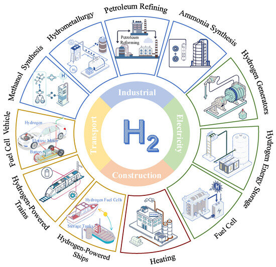
Figure 1.
Multiple application scenarios for hydrogen.
Hydrogen-based energy storage addresses the intermittency of offshore wind energy, but its practical application remains constrained by storage and transportation challenges. Superconductivity, characterized by its lossless power transmission and high conversion efficiency, presents a promising solution to enhance the integration and application of renewable energy systems [10]. High-temperature superconductivity (HTS), in particular, has demonstrated significant potential for advancing offshore wind energy applications, especially in optimizing hydrogen production systems. Its combination with renewable energy represents a promising pathway to overcome existing limitations and improve energy system efficiency. For example, the development of HTS wind turbines, which significantly reduce equipment weight and size while increasing power generation efficiency, represents a major breakthrough in the application of superconductivity to offshore wind energy [11]. Currently, the successful validation of the European Eco Swing project, which has advanced the technical feasibility of HTS wind turbines and completed on-site testing [12], marks an important milestone in the application of superconductivity to renewable energy. Notably, the Superconductivity and New Energy Center at Hunan University has pioneered the concept of offshore integrated superconducting wind power hydrogen production, further advancing the practical application of superconductivity in renewable energy systems [13].
To overcome these limitations from offshore wind power curtailment, this research developed a novel superconducting wind power generation and hydrogen production technology. And it aims to provide a comprehensive analytical framework for offshore superconducting wind power hydrogen production systems and to explore innovative technical pathways and theoretical foundations for the large-scale and sustainable production of green hydrogen in the future. To address this issue, this paper firstly reviews the research progress of applying HTS technology to wind turbines. Secondly, the mainstream technologies for hydrogen production from electrolytic water are reviewed, and the characteristics of these technologies are compared and analyzed. Moreover, given that hydrogen storage and transportation have historically been one of the major challenges in hydrogen energy applications, this paper presents a detailed analysis of various hydrogen storage methods. Then, the conceptual design of an offshore superconducting wind power hydrogen generation system is proposed, and the system operation modes for different functional requirements are outlined. Furthermore, this study examines the technical advantages and practical application potential of hydrogen production, storage, and transportation within the system. Finally, this paper prospects the main challenges for the successful operation of the system and proposes a reference direction for subsequent related research.
2. Offshore Superconducting Wind Power Generation
In comparison with onshore wind energy, offshore wind energy offers more stable and stronger wind speeds, making its development an inescapable trend. China features a coastline of 18,000 km, offering immense potential for offshore wind power development [14,15]. As of November 2024, China’s newly added offshore wind power grid-connected capacity reached 2.47 million kilowatts, bringing the total grid-connected capacity to 39.1 million kilowatts [16]. And China is planning to build 23 offshore wind farms with a total capacity of 66.9 GW by 2030 [17]. This growth trend is expected to drive technological innovation in offshore wind turbines and advancements in offshore wind power applications. However, as offshore turbine power ratings transition from the 5 MW era to the 15–20 MW era, the increasing average power ratings suggest significant growth in turbine size and blade length [18]. This trend indicates significant construction costs and operational challenges for offshore wind power development. Superconducting wind turbine generators, which utilize superconducting materials in wind power generation technology, enhance turbine efficiency and power density while simultaneously reducing generator weight and size [19].
Currently, the application of second-generation HTS materials has become one of the core technologies for superconducting wind turbines [13]. These materials exhibit excellent current-carrying capacity at liquid nitrogen temperatures (around 77 K) and are becoming increasingly affordable [20], paving the way for practical applications. Research on large-capacity wind turbines typically focuses on four types: direct-drive permanent magnet synchronous generator (PMSG) [21], salient-pole superconducting generator (S-SCG) [22], non-salient-pole superconducting generator (NS-SCG) [23], and fully superconducting generator (FSCG) [24]. FSCGs leverage the zero-resistance characteristics of HTS materials to significantly enhance current density and electromagnetic efficiency, thereby offering a technical pathway for lightweight design and high-power density in wind turbines. As exemplified by the EU Horizon 2020-funded EcoSwing project, the world’s first full-scale superconducting generator integrated into a grid-connected wind turbine was successfully developed and validated under operational conditions. The EcoSwing generator employed REBCO HTS tapes, operating in a liquid nitrogen-cooled environment (77 K, approximately −196 °C), achieving a current density over 100 times higher than conventional copper windings. This drastically reduced the required cross-sectional area of the windings and material consumption. Furthermore, through optimized electromagnetic design, the overall weight of the generator was reduced by more than 40% compared to PMSGs of equivalent power capacity [10]. The characteristic comparison of the four types of wind turbine generators is shown in Figure 2. Superconducting generators eliminate the need for traditional iron cores, thereby significantly reducing generator weight and increasing power density [25].
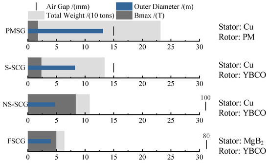
Figure 2.
Comparison of the characteristics of four types of 10 MW class wind turbine generators.
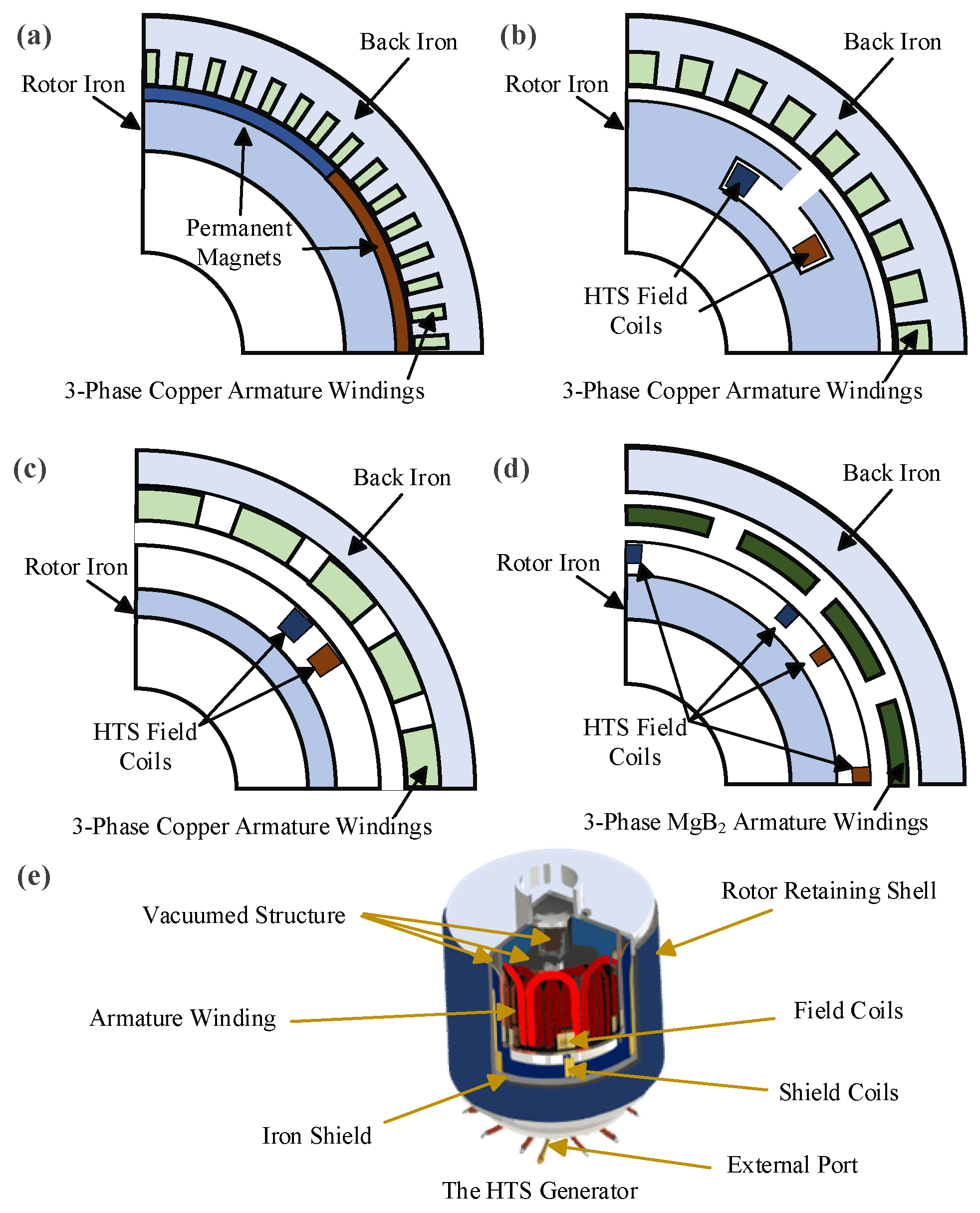
The conceptual diagrams of the four types of wind turbines are shown in Figure 3a–d. It can be seen that the PMSG features a permanent magnet rotor and copper armature windings on the stator side. The S-SCG utilizes YBCO superconducting wires for its field coils and copper-based distributed armature windings. The NS-SCG also incorporates YBCO superconducting coils and copper armature windings, but it employs an air-core stator structure. Compared to the S-SCG, the NS-SCG is lighter in weight but comes at a higher cost. The FSCG offers the greatest potential for lightweight design. It features an air-core structure with small air gaps, and both the coils and armature windings are housed within the same cryogenic container, reducing the overall diameter of the generator [26].
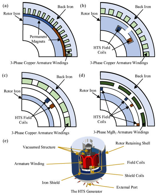
Figure 3.
Schematic diagram of (a) PMSG, (b) S-SCG, (c) NS-SCG, (d) FSCG, and (e) the HTS generator structure.
The structure of a typical HTS generator is shown in Figure 3e. Test results of the EcoSwing program showed that the generator achieved a power output of up to 1 MW at a rotational speed of 14.5 rpm [10]. While the cost of HTS materials has decreased, large-scale application still faces significant barriers due to high initial investment costs. The long-term stability of superconducting generators and their ability to withstand harsh climatic conditions require further validation. Currently, most HTS wind generators remain at the laboratory or pilot stage.
The characteristics of commercially available HTS wires and tapes are shown in Table 2. Bi-2212 and Bi-2223, as bismuth-based HTS materials, operate at critical temperatures of 110 K and 125 K, respectively, making them suitable for cooling with liquid nitrogen, which reduces maintenance costs. In contrast, REBCO, based on iron selenides, operates at a lower critical temperature of approximately 50 K, necessitating more complex cryogenic systems. As shown in the data, REBCO exhibits a higher current-carrying capacity, enabling it to transmit more power in the same cross-sectional area. Nevertheless, the mechanical properties of HTS materials must be optimized to address the challenges posed by the marine environment, including humidity, salt fog, and vibrations. Notably, Bi-2223, with its higher critical temperature, demonstrates superior stability and reliability in these demanding conditions.
Table 2.
Comparison of characteristics of commercially available HTS wires and tapes (some data in the table refer to the literature in [27,28,29,30,31]).
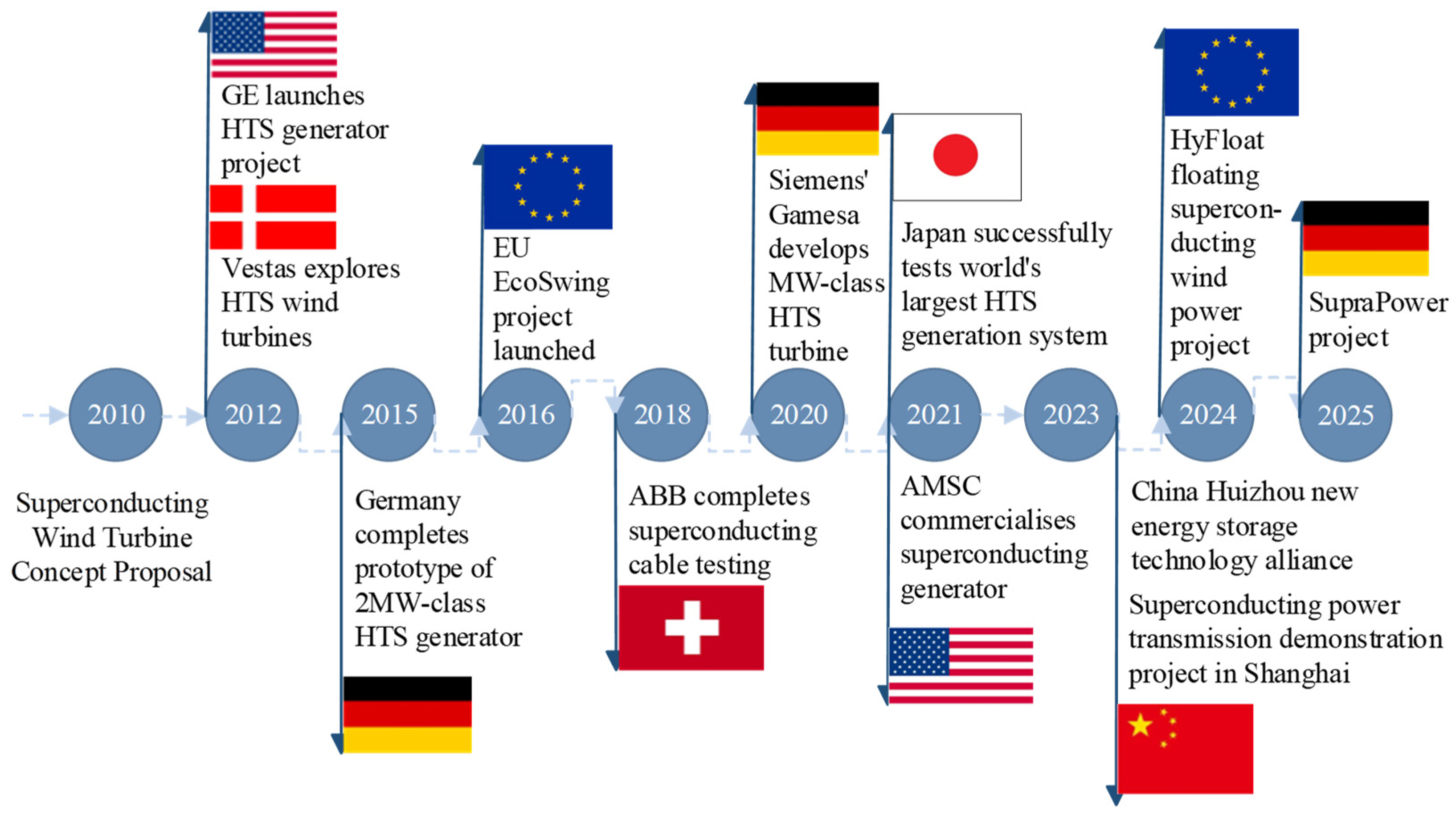
Figure 4 lists the breakthrough key projects in the field of superconducting generators that have been carried out in various countries in recent years. As can be seen from the figure, the technological maturity of superconducting motors has gradually increased. From the very beginning of conceptual research and design to the recent commercial applications, research on this subject has been continuously deepened.

Figure 4.
Timeline of the development of key engineering programs in superconducting generators.
HTS wind turbine generators rely on advanced cooling technologies, such as liquid nitrogen cooling systems, to maintain temperature control and ensure long-term operation in insulated vacuum environments. Therefore, the cooling systems require specialized designs to ensure long-term reliable operation under deep-sea conditions, including high pressure and high salinity. In the future, superconducting wind turbines can be integrated with energy storage and hydrogen production to form an integrated system for power generation, energy storage, chemical production, and power supply, thereby further enhancing the economic viability and flexibility of wind power.
3. Hydrogen Production and Storage
With the gradual development of offshore wind power projects, the construction costs escalate disproportionately. Offshore wind power platforms demonstrate stochastic power output characteristics in renewable energy generation, leading to low electricity utilization efficiency [5]. Hydrogen, as a form of chemical energy storage, can address the intermittency issues associated with renewable energy. Since the economic benefit of selling hydrogen directly to users after hydrogen production from offshore wind power is higher than converting it into electricity for sale [32,33], converting electricity transmission into hydrogen transport helps reduce the construction costs of offshore wind power and improves energy utilization efficiency. However, hydrogen is not suitable for long-term storage and is highly explosive, creating significant risks during the transportation process. Therefore, hydrogen storage and transport methods applicable to offshore wind power hydrogen production still need to be explored. This chapter focuses on hydrogen production technologies from electrolytic water and hydrogen storage and transport methods for offshore wind farms.
3.1. Electrolysis Technologies
Hydrogen has been extensively researched, and some production processes have already matured and been put into engineering applications. Currently, the main methods for hydrogen production are steam methane reforming and water electrolysis [34]. The former generates 4 mol of hydrogen and 1 mol of carbon dioxide from one molecule of methane and two molecules of water [35,36]. While it offers high production efficiency, it is associated with greenhouse gas emissions. The reaction is endothermic, requiring heat input either from fossil fuel combustion or electrical energy, resulting in significant energy consumption and potentially more greenhouse gas emissions [37]. Therefore, to improve energy efficiency and reduce carbon emissions, water electrolysis for hydrogen production has become a more advocated method, and it can be further categorized into several different types.
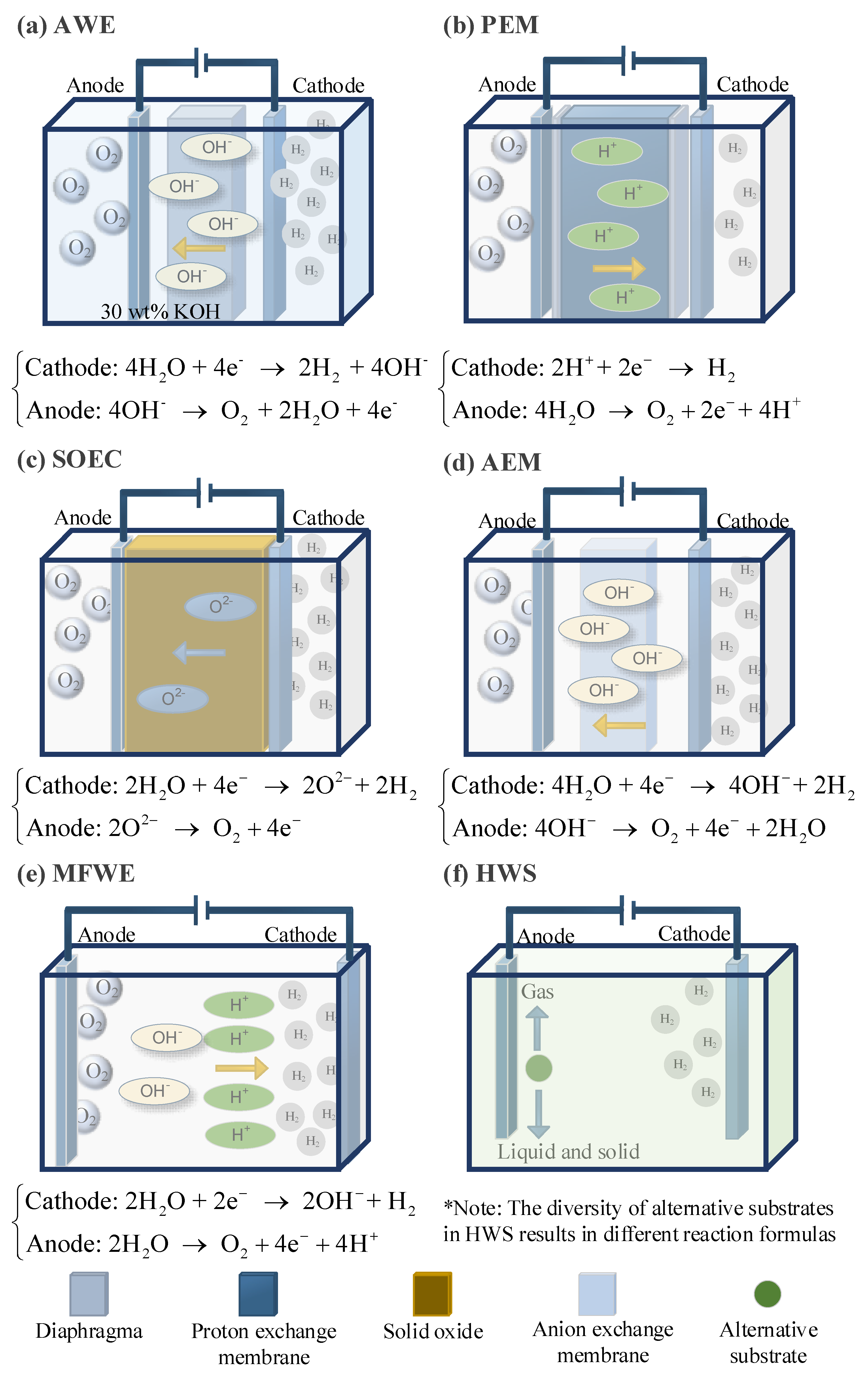
The alkaline water electrolysis (AWE) system consists of electrodes and a membrane, as shown in Figure 5a. The membrane must be permeable to the ions in the water but impermeable to the gas molecules that vaporize from the water [37]. When an electric current is applied to the electrodes, protons in the water are reduced to hydrogen gas at the cathode, and hydroxide ions are oxidized to oxygen gas at the anode [38]. The advantage of this system is that under high-pressure conditions, the energy required for subsequent hydrogen treatment is low. However, the disadvantage is that gas crossover induces <99.5% H2 purity at 30 bar [39].
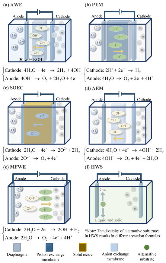
Figure 5.
Schematic diagram of six main water electrolysis methods for hydrogen production.
Proton exchange membrane (PEM) electrolysis technology has a fast response time and can follow the intermittent power load from renewable energy sources, making it widely applied in current offshore wind power hydrogen production platforms [8]. In this technology, water is replaced by a proton-conductive polymer membrane as the electrolyte, as shown in Figure 5b. This membrane is impermeable to gases, and the reactions at the electrodes differ from those in AWE; only protons and electrons can be transferred between the electrodes [40]. The cathode material typically uses platinum deposited on carbon, while the anode is commonly made from iridium or ruthenium catalysts [41]. However, the efficiency of PEM is still lower than that of AWE.
Solid oxide electrolysis (SOEC) technology uses an oxygen ion membrane, with the most common membrane being yttria-stabilized zirconia [42]. The typical electrode material is nickel metal–ceramic. Compared to the previous two electrolysis methods, this requires the least amount of electrical energy and has a modular stack architecture, making it usable across a wide pH range [43,44]. The schematic diagram is shown in Figure 5c.
Anion exchange membrane (AEM) water electrolysis technology uses an anion exchange membrane as the electrolyte to produce hydrogen through water electrolysis, which is shown in Figure 5d. The main structure consists of the anion exchange membrane and two transition metal catalysts [45]. Typically, pure water or low-concentration alkaline solutions are used as the electrolyte, with inexpensive non-metallic materials serving as the catalysts. This technology combines the advantages of AWE and PEM, allowing for the use of non-precious metal catalysts in an alkaline working environment, and the membrane-electrode-like structure enables high-pressure hydrogen production. However, this technology still has significant room for improvement before large-scale commercialization, as the development and application of core components, such as anion exchange membranes, are not yet fully mature [4].
Membrane-free water electrolysis (MFWE) technology features the simplest setup, which is based on parallel electrodes, as shown in Figure 5d. In this system, the electrolyte flows parallel to the electrodes towards two separate outlet channels at the end of the device [8]. Utilizing the Sege Silberg effect, bubbles are fixed on the electrolyte surface and are converted [46]. By flowing the electrolyte through the channels and into separate outlets, the hydrogen and oxygen gases are separated from each other under the influence of the water flow [47].
The traditional water electrolysis process suffers from slow electrode reactions, which significantly hinder the process, especially the oxygen evolution reaction at the anode, leading to high overpotentials. Currently, emerging hybrid water electrolysis (HWS) strategies are proposed by integrating thermodynamically favorable electrooxidation reactions and hydrogen evolution reactions at the cathode [48]. When the anode additives are oxidized into gaseous products, the substrate acts merely as an electron donor in a sacrificial reaction, known as the sacrificial reactant-assisted electrochemical hydrogen production [48]. The schematic diagram of the reaction principle is shown in Figure 5e. A limitation of this approach is that some reactions may produce by-products such as carbon dioxide and nitrogen [49,50].
A comparison of the characteristics of the six water electrolysis reactions is shown in Table 3. It can be seen that the first three are relatively mature technologies and that AEM, MFWS, and HWS are still in the laboratory stage, but their high efficiency in hydrogen production suggests that they have great potential. Especially, HWS technology has various reaction forms with different substrates, which is worthy of deeper exploration.
Table 3.
Comparison of six water electrolysis reactions (some data in the table refer to the literature in [4,8,48]).
However, compared to several other technologies, research at this stage has found that PEM technology is more suitable for application in offshore wind platforms. Firstly, because wind power has strong volatility, PEM technology has a very fast response speed, so the coupling of the two is better. Secondly, the PEM reaction devices can be modified into a compact membrane module, which reduces the size of the equipment. If offshore wind power can be mediated by energy storage technology, AWE technology, which has been put into large-scale commercialization, is also a good choice for hydrogen production applications.
3.2. Hydrogen Storage Technologies
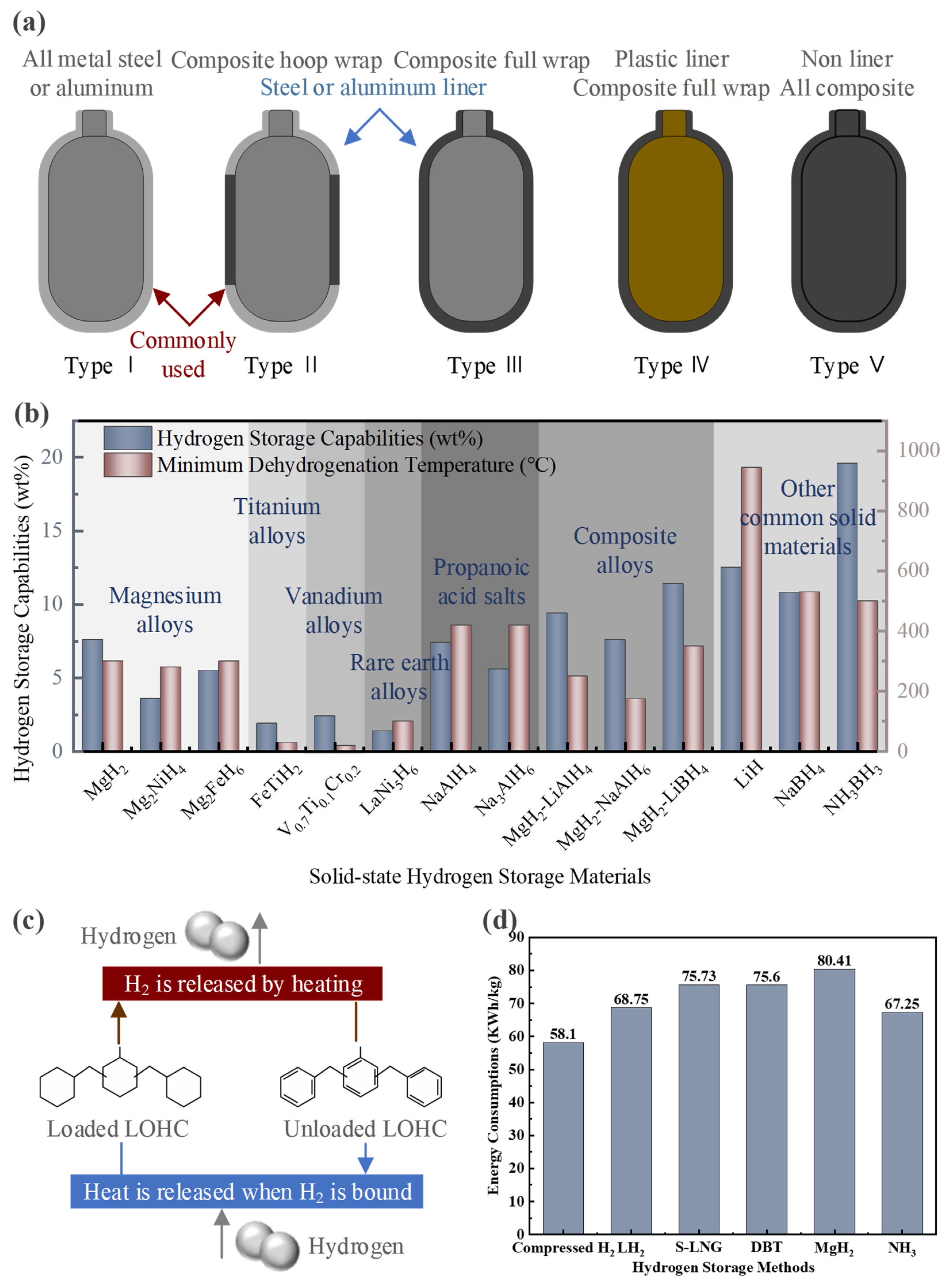
The safety of hydrogen storage has always been one of the key research areas in hydrogen energy applications. Currently, six basic forms of hydrogen storage technology have been developed worldwide. Firstly, research on high-pressure gaseous hydrogen storage has led to the development of Type I-V composite vessels, with the maximum gas storage pressure reaching over 70 MPa [51]. The schematic diagrams of five kinds of tanks are shown in Figure 6a. However, as the hydrogen storage capacity of these tanks increases, the cost of storing each kilogram of hydrogen also rises nearly tenfold. Under such high pressure, a volumetric density of 40.1 g H2/L (0.81 kWh/L) of hydrogen energy can be stored [8]. Additionally, the process of compressing hydrogen results in significant energy loss, leading to less-than-ideal overall storage efficiency. The characteristics of the five high-pressure hydrogen storage tanks are shown in Table 4.

Figure 6.
(a) Schematic diagram of five types of hydrogen storage tanks. (b) Comparison of solid hydrogen storage materials. (c) Liquid organic hydrogen storage mechanism. (d) Comparison of energy consumption of different hydrogen storage methods.
Table 4.
Comparison of five kinds of hydrogen storage tanks (some data in the table refer to the literature in [52,53,54]).
Secondly, LH2 appears to hold more energy than compressed hydrogen. When the ambient temperature is cooled to −253 °C, hydrogen is compressed to a liquid state, which increases its density by a factor of 775 [51]. The process for making LH2 is more complex, and there are several types of processes, including cascade refrigeration systems (Linde-Hampson) [55], expansion-based cycles (Claude) [56], and helium cryogenic systems [57]. Of these, the last one is by far the most common and widely used in industrial production [58]. Also, as a liquid energy source, the energy density of diesel is much higher than that of LH2. That is, under the same volume conditions, diesel can provide about four times the energy of LH2.
Thirdly, liquid fuels can be produced from gaseous mixtures of hydrogen and carbon dioxide, completing the energy conversion and thus increasing energy efficiency. Examples include synthetic diesel production [59], synthetic methane production (S-LNG) [60], methanol production [61], and formic acid production [62], as shown in Table 5. However, it can be seen that the synthetic diesel production process only produces a mixture of hydrocarbons and only one-third of the hydrogen molecules are stored in the new fuel. The production of synthetic methane is highly exothermic, generates a lot of waste heat, and half of the by-products are water, with only one-half of the hydrogen molecules being utilized. Green methanol uses a cheaper transition metal catalyst in the reaction and loses less hydrogen than other hydrogen storage molecules, but one-third of the hydrogen molecules are still converted to water. In order to improve the selectivity of hydrogen molecules, there is an increasing amount of research on synthesizing formic acid at this stage. But the purity of the formic acid is difficult to guarantee. The use of different catalysts results in different products, and it may be accompanied by the production of harmful gas.
Table 5.
Reaction conditions for the synthesis of diesel, methane, methanol, and formic acid (some data in the table refer to the literature in [59,60,61,62]).
In addition, most metals have the ability to react with hydrogen to form metal hydrides. The hydrogen storage capacity of these metal hydrides is shown in Figure 6b. Current research focuses on using the lightest metals as storage materials. These metal hydrides, however, tend to be chemically stable, requiring very stringent conditions to release hydrogen. For instance, the lightest metal, lithium, can form LiH with a hydrogen content of 12.5 wt%, but its dehydrogenation temperature reaches as high as 944 °C [63].
The fifth approach is organic LH2 storage technology. It involves fixing hydrogen to aromatic organic compounds through hydrogenation reactions, creating stable LH2 organic compounds. The mechanism is shown in Figure 6c. Aromatic liquid molecules, composed of homocyclic and heterocyclic aromatic hydrocarbons, enable hydrogen storage and release through reversible one-to-one reactions. Table 6 shows the hydrogen storage and dehydrogenation reaction conditions of three common organic LH2 storage materials: toluene, dibenzyl toluene (DBT), and N-ethyl carbazole. However, the hydrogenation and dehydrogenation equipment for such reactions is complex, and side reactions are prone to occur.
Table 6.
The characteristics of common organic LH2 storage materials (some data in the table refer to the literature in [64]).
Finally, another common way to store hydrogen is to use ammonia (NH3) as a carrier for hydrogen storage [65]. In offshore wind power hydrogen production systems, adopting ammonia as a hydrogen carrier is both necessary and advantageous. Hydrogen has a low density and requires either high pressure or ultra-low temperatures for storage and transport (350–700 bar or −253 °C), resulting in high costs and low safety. Ammonia, on the other hand, liquefies under mild conditions (10 bar or −33.4 °C), addressing these issues effectively. Additionally, liquid ammonia has a higher energy density (12.9 MJ/L) compared to LH2 (8.5 MJ/L), enabling more efficient transportation [66].
Since the development of the Haber–Bosch (HB) process over 100 years ago, ammonia synthesis technology has made significant advancements in energy efficiency, catalyst development, and process optimization [67]. More importantly, ammonia is increasingly recognized as a potential clean fuel and hydrogen carrier [9,68]. The core of the HB process is the reaction of nitrogen and hydrogen under high temperature and pressure conditions (400–500 °C and 20–40 MPa) to produce ammonia, using a Fe3O4-based catalyst [69]. The energy consumption of the process primarily comes from hydrogen production [70,71].
One of the limitations of current ammonia production is the use of hydrogen as a raw material, which is traditionally produced from fossil fuels, releasing large amounts of CO2 during the process. To reduce environmental impact, the future of ammonia synthesis lies in the use of green hydrogen derived from renewable energy sources to produce green ammonia. Another limitation is that while traditional large-scale ammonia production is cost-effective, its operational flexibility is limited, making it difficult to integrate with wind, solar, and water electrolysis technologies [68].
Due to ammonia having a very low density at atmospheric pressure, it is not suitable for long-term storage. It is typically liquefied under low-temperature or high-pressure conditions to meet the needs of small-scale storage. By cooling ammonia gas to low temperatures (−33.34 °C) or pressurizing it to high pressures (approximately 0.8–1 MPa), it can be converted into liquid ammonia [72,73,74,75]. Compared to LH2, liquid ammonia storage is more energy-efficient and less demanding [72]. This is because liquid ammonia transport shares similarities with existing liquefied natural gas technology, resulting in relatively low production costs [73]. With its high volumetric energy density, ammonia enables much more efficient transportation than hydrogen [74]. In fact, ammonia is significantly cheaper to store due to its lower liquefaction energy and existing infrastructure compatibility [75]. Eventually, the higher volumetric energy density makes it more efficient for transport compared to hydrogen. The energy consumption comparison of all the aforementioned hydrogen storage methods is shown in Figure 6d. Compressed hydrogen has the lowest energy consumption, followed by ammonia synthesis. Solid metal hydrides have the highest energy consumption. Therefore, both compressed hydrogen and ammonia synthesis are economically advantageous storage and transport methods in practical engineering applications.
4. Conceptual Design of Offshore Superconducting Wind Power Generation for Hydrogen Production
Offshore wind farms, with their access to large amounts of renewable energy, are ideally suited for hydrogen production from electrolysis, solving the problems of carbon emissions and renewable energy adoption in one go. As research into wind power and offshore chemical production progresses, the next generation of wind turbine designs will be rated at more than 20 MW [76,77]. In this case, HTS generators achieve 58% mass reduction vs. permanent magnet counterparts at a 20 MW rating [78,79]. This section presents a conceptual design of an offshore wind power hydrogen production system and the different modes of operation of this system. Notably, based on the discussion in the previous section, the system chooses PEM to produce hydrogen, and ammonia will be utilized to store hydrogen.
Firstly, the offshore HTS wind turbine converts wind energy into electrical energy while utilizing superconducting materials to reduce power losses. Next is the superconducting power transmission system, which can transmit high-power electricity under low-temperature conditions with extremely low resistance and energy dissipation, making it suitable for large-scale, long-distance transmission. Thirdly, seawater is converted into fresh water that can be electrolyzed through a desalination unit, where the electrolyzer works to produce hydrogen and oxygen. Direct electrolysis of seawater to produce hydrogen has now been partially studied, but the technology is still in the laboratory testing phase [80]. This system still considers hydrogen production in the form of a desalination unit coupled with an electrolysis tank. The electricity input into the electrolyzer splits the water into hydrogen, which can be stored as energy, and oxygen, which is a by-product. Fourth, the ammonia synthesis device includes a nitrogen extraction system. In addition, the system requires a power dispatch and management module, which is responsible for managing the power demand across various stages such as wind power generation, hydrogen production, and ammonia synthesis, ensuring the system operates efficiently and stably [32]. Real-time monitoring of wind power output, water electrolysis efficiency, and the ammonia synthesis process is required, along with energy flow management and dispatching. Based on the combination methods of offshore superconducting wind power and water electrolysis for hydrogen, the systems can be sorted into three main types. As shown in Figure 7, each type has different configurations, which in turn affects how the system operates and how it performs in terms of energy efficiency.
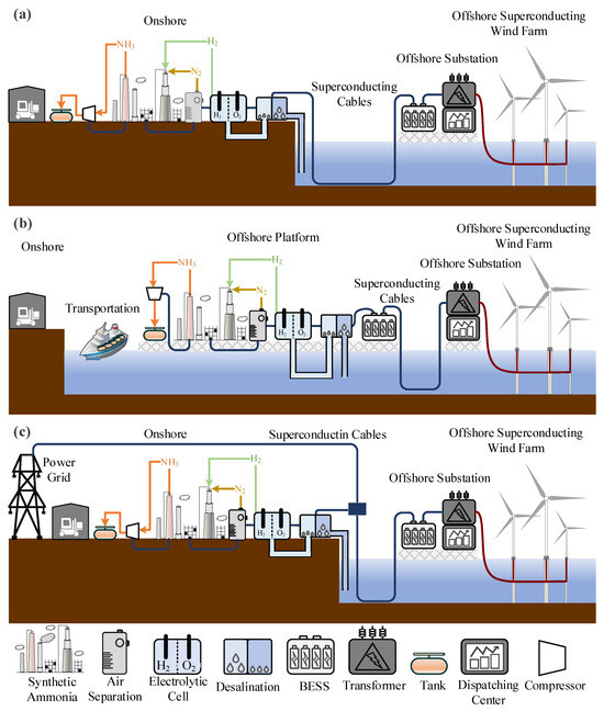
Figure 7.
(a) Off-grid offshore superconducting wind power generation combined with onshore hydrogen production. (b) Off-grid offshore superconducting wind power generation combined with offshore hydrogen production. (c) Grid-connected offshore superconducting wind power generation combined with onshore hydrogen production.
Off-grid systems direct all the electricity generated by offshore wind farms to onshore facilities for chemical production. This system is independent of traditional power grids, does not sell electricity to onshore users, and exclusively provides chemical products. The primary function of the system is centered on chemical production, with electricity sales being secondary. The power dispatch module focuses solely on balancing wind power generation with chemical production.
Off-grid systems can be further divided into two types: onshore chemical production (as shown in Figure 7a) and offshore chemical production (as shown in Figure 7b). The former avoids the high economic costs associated with offshore ammonia storage and transportation as well as the power losses incurred during electricity transmission. This type of system can be deployed in remote offshore regions without grid connections. However, its disadvantages include the need for a higher degree of self-sufficiency and technological advancements in long-distance superconducting power transmission. The latter significantly reduces land usage and shortens electricity transmission distances. However, it comes with higher construction and maintenance costs for offshore facilities, and the storage and transportation of hydrogen and ammonia offshore also increase expenses. As a result, in practical engineering applications, deploying off-grid systems in nearshore wind farms closer to the coast is more economical.
The grid-connected system integrates offshore superconducting wind farms and hydrogen production with the power grid. As shown in Figure 7c, the grid provides stability to support water electrolysis. This system balances chemical production and power grid integration, allowing flexible adjustment of wind power output while relying on the grid to provide stable electricity, thereby accommodating fluctuations in power demand. The power dispatch module in a grid-connected system needs to balance power distribution between electricity and chemical production while also managing the coupling between the system and the grid. The advantages of such systems include leveraging the grid’s stability to achieve complementary operation between wind power and the grid, ensuring a stable electricity supply. Additionally, with electricity transmitted via the grid, offshore facilities are not solely responsible for power production, which reduces the infrastructure requirements and costs associated with offshore wind farms. However, grid-connected systems depend on grid stability, and any grid faults or disruptions can affect their normal operation. Moreover, implementing such systems requires extensive grid infrastructure, particularly for electricity transmission lines between offshore wind farms and chemical facilities, necessitating additional investments. Lastly, the complexity of power dispatch and equipment operation in grid-connected systems requires focused research and precise control strategies.
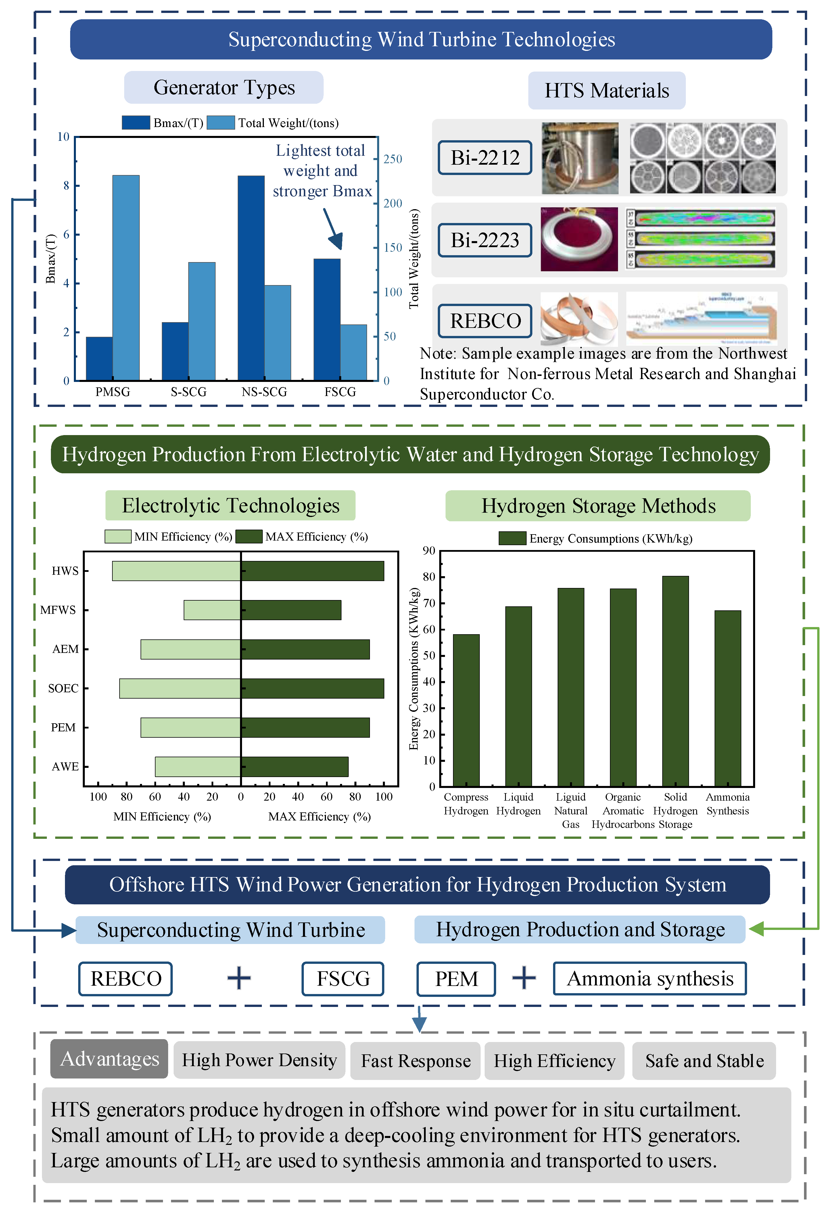
In summary, after investigating the superconducting generator technology, electrolytic water hydrogen production technology, and hydrogen storage technology, this paper concludes that the offshore superconducting wind power hydrogen production system has certain advantages over the conventional offshore wind power system. Summarized as shown in Figure 8, hydrogen production from superconducting wind power in this system can help to curtail abandoned wind and improve the efficiency of hydrogen production. Secondly, a small portion of the produced LH2 can be refluxed and used to provide the deep-cooling environment required for the operation of superconducting wind turbines, saving resources and reducing costs. Finally, most of the hydrogen produced by the system is combined with air to synthesize ammonia, and the ammonia is shipped to users as the final product, largely reducing the risks and costs of hydrogen storage and transportation. However, the implementation of this system still faces many technical challenges, which will be discussed in detail in the following section.
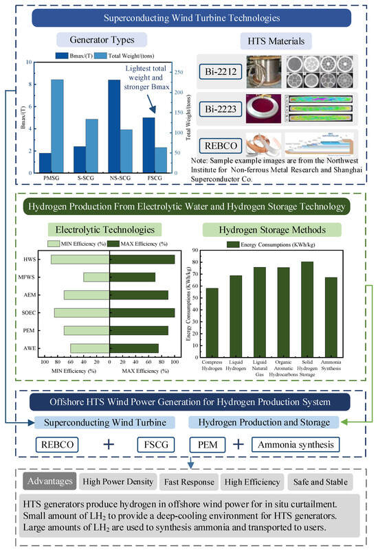
Figure 8.
Summary of this review study.
5. Challenges for Hydrogen Production in Offshore Superconducting Wind Farms
The integration of superconducting technology with offshore wind power systems designed for chemical production represents a groundbreaking advancement in clean energy utilization. By leveraging the unique properties of superconductors, such systems aim to enhance efficiency and reduce energy dissipation. However, the implementation brings significant technical, operational, and economic challenges that must be addressed for the successful implementation of the system.
5.1. Application of Superconducting Technology
The integration of superconducting technology with offshore wind power systems designed for chemical production represents a groundbreaking advancement in clean energy utilization. By leveraging the unique properties of superconductors, such systems aim to enhance efficiency and reduce energy losses. However, significant technical and operational challenges must be addressed for successful deployment.
Superconducting technology faces critical obstacles in offshore environments, particularly regarding material stability under harsh marine conditions. High humidity, salinity, and corrosive atmospheres degrade superconducting materials, undermining their reliability. Cryogenic cooling systems introduce further complexities: compact and energy-efficient refrigeration designs are essential for maintaining low-temperature operation. Although superconductors exhibit zero resistance under ideal conditions, energy losses persist in alternating current systems due to imperfect insulation. Minimizing these losses is vital for achieving high efficiency.
While superconducting generators offer higher power densities and reduced weight compared to conventional designs, their cryogenic systems increase overall mass and complexity. For example, integrating cryogenic components with offshore turbines demands advanced engineering solutions to ensure structural integrity. Maintenance poses additional difficulties: offshore turbines operate in remote locations, making repairs to cryogenic systems more challenging than for conventional generators. The intermittent nature of wind power further complicates system operation.
Coupling superconducting components with hydrogen production systems presents dynamic integration challenges. Wind power’s variability conflicts with the stable energy inputs required for processes like water electrolysis. To address this, adaptive control strategies are needed to balance supply–demand without efficiency loss.
5.2. Safety and Stability Concerns
In this energy system, the interaction of high-risk materials, complex equipment, and external environmental factors poses a significant challenge to the safety and stability of the system. Hydrogen and ammonia, as energy carriers, are key sources of risk to system safety due to their inherent properties (e.g., flammability and toxicity). In addition, the low-temperature operational requirements of superconducting devices, the corrosive environment of offshore systems, and the intermittent nature of wind energy further add to the complexity and vulnerability of the system.
Hydrogen poses a risk of leakage and explosion due to its high diffusivity and flammability. Studies have shown that the minimum ignition energy of hydrogen is only 0.019 mJ, which makes it highly susceptible to accidents caused by static electricity or sparks [81,82]. In order to deal with this problem, some recent studies have proposed the use of fiber optic sensor technology for real-time leakage detection [82]. In addition, to prevent secondary hazards associated with hydrogen combustion, recent studies have also proposed the use of flame retardant materials and explosion-proof structural designs, such as the use of modified ceramic materials as the inner wall of the hydrogen storage vessel, to improve the system’s resistance to ignition [83]. The toxicity of ammonia is also a concern. Ammonia has an acute exposure limit of 30 ppm, and long-term exposure poses a serious threat to human health [84]. In order to reduce the risks associated with ammonia leakage, researchers have proposed the combination of intelligent ventilation systems and chemisorption techniques. For example, an ion mobility spectrometry-based ammonia sensor capable of high-precision detection in less than 1 s and integrated with an automatic ventilation system to significantly reduce the risk of leakage [85].
The operation of superconducting devices relies on a low-temperature environment, and the failure of the refrigeration system may cause the superconducting materials to lose their superconducting properties, which may lead to system failure or even device damage. For this reason, recent research has focused on the fault diagnosis and redundancy design of refrigeration systems, and Blumenfeld et al. [86] proposed a machine learning-based fault prediction model, which can predict potential faults in advance and provide optimized operation solutions by analyzing the operational data of the refrigeration system. In addition, to address the thermal stresses generated by superconducting devices during the quench process, researchers have proposed multi-layer heat shield designs and fast quench protection mechanisms. For example, Bagni et al. [87] developed a new type of heat shielding material, which can effectively disperse the heat during the quench process and reduce the thermal stress damage to the device.
Offshore systems are exposed to high salt, high humidity, and strong wind and wave environments for a long time, which makes them vulnerable to corrosion and extreme weather. Recent research has made significant progress in corrosion-resistant materials. A novel nanocomposite coating technology has been proposed recently, which significantly improves the corrosion resistance of equipment by coating metal surfaces with a composite of highly corrosion-resistant epoxy resin and graphene nanosheets [88]. In addition, in order to cope with extreme weather (e.g., typhoons and thunderstorms), researchers recently proposed intelligent monitoring and rapid response strategies. Wang et al. [89] developed a real-time environmental monitoring system based on IoT technology, which is capable of predicting in advance the impacts of extreme weather on the system and activating an automatic protection mechanism to minimize the loss of equipment.
The intermittent nature of wind energy places higher demands on system stability. Recent studies have made significant progress in wind power prediction and system control. For example, Alkhayat Ghadah and Mehmood Rashid [90] provided a review of a deep learning-based wind power prediction model with a prediction accuracy of up to 95%, which significantly improves the operational efficiency of the system. In addition, modular design and distributed control strategies have proved to be effective solutions in terms of system architecture design. Luna et al. [91] proposed a modular wind power generation system, which achieves fast fault isolation and recovery by dividing the system into multiple independent units, reducing the risk of the system as a whole.
In order to achieve comprehensive safety and stable operation of the system, the above improvement measures need to be systematically integrated and optimized. By establishing a multi-level safety warning system and an intelligent control platform, it is possible to realize real-time monitoring and rapid response to all parts of the system. Recent research in integrated system design proposed an energy management system based on a cloud platform, which is able to realize the synergistic control of hydrogen, ammonia, superconducting equipment, and a wind energy system, and significantly improve the overall performance of the system [92].
6. Conclusions
This paper provides a comprehensive review of the technologies and operational modes involved in offshore superconducting wind power generation for hydrogen production. The investigation reveals the pivotal role of HTS technology in advancing wind turbines to the 20 MW era, which is critical for enhancing power generation efficiency and reducing construction costs.
This study also evaluates various hydrogen storage methods, including compressed hydrogen, LH2, solid-state hydrogen storage, liquid fuels, aromatic organic LH2 carriers, and ammonia. The analysis demonstrates that ammonia stands out as a superior option due to its lower energy consumption in production, higher secondary utilization value, and reduced risks and costs associated with storage and transportation in an offshore environment. This makes ammonia a better choice than hydrogen for long-distance maritime transport and distribution to end-users. Furthermore, this research examines the composition and operational characteristics of different offshore superconducting wind power hydrogen production systems. The results indicate that off-grid systems offer higher chemical production capacity, while grid-connected systems provide the flexibility to both generate hydrogen and exchange power with the grid.
Finally, this review identifies and discusses the challenges in constructing and operating offshore superconducting wind power systems from two key perspectives, which are the application of superconducting technology and system safety and stability. These challenges highlight the need for further research and development to address technical, economic, and operational barriers. This paper aims to provide valuable insights and recommendations for future research and development in this emerging field, contributing to the advancement of sustainable renewable energy systems for hydrogen production.
Author Contributions
Conceptualization, C.Z. and Y.Z.; methodology, C.Z.; formal analysis, L.S.; data curation, L.S., F.S., L.C., S.L., Z.Z., L.Z., J.W. and X.W.; writing—original draft preparation, L.S.; writing—review and editing, L.S. and Y.Z.; funding acquisition, L.S. and Y.Z. All authors have read and agreed to the published version of the manuscript.
Funding
This research was funded in part by the Young Elite Scientists Sponsorship Program by CAST under Grant 2021QNRC001, in part by the Hunan Provincial Natural Science Foundation Outstanding Youth Program under Grant 2021JJ20013, and in part by the Hunan Province Innovation Platform Talent Program-Huxiang Young Talents under Grant 2021RC3058.
Data Availability Statement
Data are contained within the article.
Acknowledgments
This work was supported by the Superconductivity and New Energy Research Centre of Hunan University, Engineering Research Center of Power Transmission and Transformation Technology, Institute of Electrical Engineering Chinese Academy of Sciences, Ministry of Education of China.
Conflicts of Interest
The authors declare no conflicts of interest.
References
- Zhang, C.; Xia, P.; Zhang, X. Multi-attribute decision-making method of pumped storage capacity planning considering wind power uncertainty. J. Clean. Prod. 2024, 449, 141655. [Google Scholar] [CrossRef]
- Wu, X.; Hu, Y.; Li, Y.; Yang, J.; Duan, L.; Wang, T.; Adock, T.; Jiang, Z.; Gao, Z.; Lin, Z.; et al. Foundations of offshore wind turbines: A review. Renew. Sustain. Energy Rev. 2019, 104, 379–393. [Google Scholar] [CrossRef]
- Diaz, H.; Soares, C.G. Review of the current status, technology and future trends of offshore wind farms. Ocean Eng. 2020, 209, 107381. [Google Scholar] [CrossRef]
- Ge, L.; Zhang, B.; Huang, W.; Li, Y.; Hou, L.; Xiao, J.; Mao, Z.; Li, X. A review of hydrogen generation, storage, and applications in power system. J. Energy Storage 2024, 75, 109307. [Google Scholar] [CrossRef]
- Luo, Z.; Wang, X.; Wen, H.; Pei, A. Hydrogen production from offshore wind power in South China. Int. J. Hydrogen Energy 2022, 47, 24558–24568. [Google Scholar] [CrossRef]
- Fan, L.; Tu, Z.; Chan, S. Recent development of hydrogen and fuel cell technologies: A review. Energy Rep. 2021, 7, 8421–8446. [Google Scholar] [CrossRef]
- Odenweller, A.; Ueckerdt, F.; Nemet, G.F.; Jensterle, M.; Luderer, G. Probabilistic feasibility space of scaling up green hydrogen supply. Nat. Energy 2022, 7, 854–865. [Google Scholar] [CrossRef]
- Van Hoecke, L.; Laffineur, L.; Campe, R.; Perreault, P.; Verbruggen, S.; Lenaert, S. Challenges in the use of hydrogen for maritime applications. Energy Environ. Sci. 2021, 14, 815–843. [Google Scholar] [CrossRef]
- Rathore, S.; Biswas, S.; Fini, D.; Kulkarni, A.; Giddey, S. Direct ammonia solid-oxide fuel cells: A review of progress and prospects. Int. J. Hydrogen Energy 2021, 46, 35365–35384. [Google Scholar] [CrossRef]
- Xu, Y.; An, L.; Jia, B.; Maki, N. Study on electrical design of large-capacity fully superconducting offshore wind turbine generators. IEEE Trans. Appl. Supercond. 2021, 31, 5201305. [Google Scholar] [CrossRef]
- Song, X.; Buhrer, C.; Brutsaert, P.; Ammar, A.; Krause, J.; Bergen, A.; Winkler, T.; Dhaller, M.; Hansen, J.; Rebsdorf, A.; et al. Ground testing of the world’s first MW-class direct-drive superconducting wind turbine generator. IEEE Trans. Energy Convers. 2020, 35, 757–764. [Google Scholar] [CrossRef]
- Ren, Z.; Zhang, S.; Liu, H.; Pu, L.; Wang, X.; Wang, Z.; Wu, M.; Chen, Z. The environmental and public health benefits of offshore wind power deployment in China. Environ. Sci. Technol. 2025, 59, 315–327. [Google Scholar] [CrossRef] [PubMed]
- Shen, L.; Zhang, C.; Shan, F.; Chen, L.; Liu, S.; Zheng, Z.; Zhu, L.; Wang, J.; Wu, X.; Zhai, Y. Review and prospects of key technologies for integrated systems in hydrogen production from offshore superconducting wind power. Energies 2025, 18, 19. [Google Scholar] [CrossRef]
- Zhang, J.; Wang, H. Development of offshore wind power and foundation technology for offshore wind turbines in China. Ocean Eng. 2022, 266, 113256. [Google Scholar] [CrossRef]
- Sun, Y.; Ai, H.; Li, Y.; Wang, R.; Ma, R. Data-driven large-scale spatial planning framework for determining size and location of offshore wind energy development: A case study of China. Appl. Energy 2024, 367, 123388. [Google Scholar] [CrossRef]
- The State Council of the People’s Republic of China. A Total of 39.1 Million Kilowatts of Offshore Wind Power had Been Built and Connected to the Grid in China. 2024. Available online: http://www.gov.cn (accessed on 18 November 2024).
- Deng, X.; Xu, W.; Xu, Y.; Shao, Y.; Wu, Y.; Yuan, W.; Qin, Z. Offshore wind power in China: A potential solution to electricity transformation and carbon neutrality. Fundam. Res. 2024, 4, 1206–1215. [Google Scholar] [CrossRef]
- Tyurkay, A.; Kirkelund, G.; Lima, A. State-of-the-art circular economy practices for end-of-life wind turbine blades for use in the construction industry. Sustain. Prod. Consum. 2024, 47, 17–36. [Google Scholar] [CrossRef]
- Abrahamsen, A.; Mijatovic, N.; Seiler, E.; Zirnigibl, T.; Traeholt, C.; Norgard, P.; Pedersen, N.; Andersen, N.; Ostergard, J. Superconducting wind turbine generators. Supercond. Sci. Technol. 2010, 23, 34019. [Google Scholar] [CrossRef]
- Shen, L.; Zhai, Y.; Zheng, Z.; Wu, X.; Zhu, L.; Wang, L.; Huang, S. Research on magnetic field distribution characteristics of 2G-HTS dynamo in superconducting wireless power supply applications. Supercond. Sci. Technol. 2025, 38, 15017. [Google Scholar] [CrossRef]
- Wei, Y.; Cheng, Z.; Si, J.; Jin, F.; Gao, C.; Gan, C. Analysis of a direct-drive permanent magnet synchronous generator with novel toroidal winding. IET Renew. Power Gener. 2021, 15, 2237–2245. [Google Scholar] [CrossRef]
- Xu, Y.; Maki, N.; Izumi, M. Electrical design study of 10-MW salient-pole wind turbine HTS synchronous generators. IEEE Trans. Appl. Supercond. 2014, 24, 5202706. [Google Scholar] [CrossRef]
- Terao, Y.; Ohsaki, H. Short-circuit accident analysis of 10 MW class superconducting wind turbine generators with different structures. In Proceedings of the 19th International Conference on Electrical Machines and Systems, Chiba, Japan, 13–16 November 2016. [Google Scholar]
- Miura, S.; Iwakuma, K.; Izumi, T. Lightweight design of tens-MW fully-superconducting wind turbine generators with high-performance REBa2Cu3Oy wires. IEEE Trans. Appl. Supercond. 2020, 30, 5204106. [Google Scholar] [CrossRef]
- Terao, Y.; Sekino, M.; Ohsaki, H. Comparison of conventional and superconducting generator concepts for offshore wind turbines. IEEE Trans. Appl. Supercond. 2013, 23, 5200904. [Google Scholar] [CrossRef]
- Terao, Y.; Sekino, M.; Ohsaki, H. Electromagnetic design of 10 MW class fully superconducting wind turbine generators. IEEE Trans. Appl. Supercond. 2012, 22, 5201904. [Google Scholar] [CrossRef]
- Wang, L.; Mu, S.; Zhang, T.; Zhou, Q. A superconducting cable with curved HTS tapes. IEEE Trans. Appl. Supercond. 2021, 31, 4805202. [Google Scholar] [CrossRef]
- Akasaka, T.; Onji, T.; Yano, S.; Zhong, Y.; Otabe, E.; Ishihara, A.; Tomita, M. Analytical and experimental evaluation of the joints in Bi-based superconducting tape for the feeder cable. IEEE Trans. Appl. Supercond. 2023, 33, 4800305. [Google Scholar] [CrossRef]
- Shiohara, K.; Sato, M.; Takahashi, Y.; Adachi, K.; Izumi, T.; Iwakuma, M. Development of a superconducting cable for aircraft electric propulsion system. IEEE Trans. Appl. Supercond. 2024, 34, 4801104. [Google Scholar] [CrossRef]
- Yu, H.; Lu, J. Superconducting transformer for superconducting cable testing up to 45 kA. IEEE Trans. Appl. Supercond. 2020, 30, 5500204. [Google Scholar] [CrossRef]
- Uglietti, D. A review of commercial high temperature superconducting materials for large magnets: From wires and tapes to cables and conductors. Supercond. Sci. Technol. 2019, 32, 53001. [Google Scholar] [CrossRef]
- De Almeida, J.; Shadman, M.; Dos Santos Ramos, J.; Bastos, I.; Silva, C.; Chujutalli, J.; Amiri, M.; Bergman-Fonte, C.; Ferreira, G.; Carreira, E.; et al. Techno-economic analysis of hydrogen production from offshore wind: The case of Brazil. Energy Convers. Manag. 2024, 322, 119109. [Google Scholar] [CrossRef]
- Armijo, J.; Philibert, C. Flexible production of green hydrogen and ammonia from variable solar and wind energy: Case study of Chile and Argentina. Int. J. Hydrogen Energy 2020, 45, 1541–1558. [Google Scholar] [CrossRef]
- van Geem, K.M.; Galvita, V.V.; Marin, G.B. Make chemicals with power. Science 2019, 364, 734–735. [Google Scholar] [CrossRef] [PubMed]
- Iulianelli, A.; Liguori, S.; Wilcox, J.; Basile, A. Advances on methane steam reforming to produce hydrogen through membrane reactors technology: A review. Catal. Rev. Sci. Eng. 2016, 58, 1–35. [Google Scholar] [CrossRef]
- Wismann, S.T.; Engbaek, J.S.; Vendelbo, S.B.; Bendixen, F.B.; Eriksen, W.L.; Aasberg-Petersen, K.; Frandsen, C.; Chorkendoff, I.; Mortensen, P. Electrified methane reforming: A compact approach to greener industrial hydrogen production. Science 2019, 759, 756–759. [Google Scholar] [CrossRef]
- Rodrıguez, P.; Sanchez-Molina, A.; Mais, C. Simple and Precise Approach for Determination of Ohmic Contribution of Diaphragms in Alkaline Water Electrolysis. Membranes 2019, 9, 129. [Google Scholar] [CrossRef]
- Rosa, V.M.; Santos, M.B.F.; da Silva, E.P. New materials for water electrolysis diaphragms. Int. J. Hydrogen Energy 1995, 20, 697–700. [Google Scholar] [CrossRef]
- Zeng, K.; Zhang, D. Recent progress in alkaline water electrolysis for hydrogen production and applications. Prog. Energy Combust. Sci. 2010, 36, 307–326. [Google Scholar] [CrossRef]
- Buttler, A.; Spliethoff, H. Current status of water electrolysis for energy storage, grid balancing and sector coupling via power-to-gas and power-to-liquids: A review. Renew. Sustain. Energy Rev. 2018, 82, 2440–2454. [Google Scholar] [CrossRef]
- Babic, U.; Suermann, M.; Buchi, F.N.; Gubler, L.; Schmidt, T.J. Review—Identifying critical gaps for polymer electrolyte water electrolysis development. J. Electrochem. Soc. 2017, 164, 387–399. [Google Scholar] [CrossRef]
- Pandiyan, A.; Uthayakumar, A.; Subrayan, R.; Cha, S.W.; Krishna Moorthy, S.B. Review of solid oxide electrolysis cells: A clean energy strategy for hydrogen generation. Nanomater. Energy 2019, 8, 2–22. [Google Scholar] [CrossRef]
- Jiang, S.P. Challenges in the development of reversible solid oxide cell technologies: A mini review, Asia-Pac. J. Chem. Eng. 2016, 11, 386–391. [Google Scholar] [CrossRef]
- Bhandari, R.; Trudewind, C.A.; Zapp, P. Life cycle assessment of hydrogen production via electrolysis e a review. J. Clean. Prod. 2014, 85, 151–163. [Google Scholar] [CrossRef]
- Li, K.; Yu, S.; Li, D.; Wang, W.; Xie, Z.; Park, E.; Fujimoto, C.; Cullen, D.; Kim, Y.; Zhang, F.; et al. Engineered thin diffusion layers for anion-exchange membrane electrolyzer cells with outstanding performance. ACS Appl. Mater. Interfaces 2021, 13, 50957–50964. [Google Scholar] [CrossRef] [PubMed]
- Talabi, O.O.; Dorfi, A.E.; O’Neil, G.D.; Esposito, D.V. Membraneless electrolyzers for the simultaneous production of acid and base. Chem. Commun. 2017, 53, 8006–8009. [Google Scholar] [CrossRef]
- Hashemi, S.M.H.; Karnakov, P.; Hadikhani, P.; Chinello, E.; Litvinov, S.; Moser, C.; Koumoutsakos, P.; Psaltis, D. A versatile and membrane-less electrochemical reactor for the electrolysis of water and brine. Energy Environ. Sci. 2019, 12, 1592–1604. [Google Scholar] [CrossRef]
- Qian, Q.; Zhu, Y.; Ahmad, N.; Feng, Y.; Zhang, H.; Cheng, M.; Liu, H.; Xiao, C.; Zhang, G. Recent advancements in electrochemical hydrogen production via hybrid water splitting. Adv. Mater. 2024, 36, 2306108. [Google Scholar] [CrossRef]
- Sun, F.; Qin, J.; Wang, Z.; Yu, M.; Wu, X.; Sun, X.; Qiu, J. Energy-saving hydrogen production by chlorine-free hybrid seawater splitting coupling hydrazine degradation. Nat. Commun. 2021, 12, 4182. [Google Scholar] [CrossRef]
- Zhang, M.; Li, H.; Duan, X.; Zou, P.; Jeerh, G.; Sun, B.; Chen, S.; Humphreys, J.; Walker, M.; Xie, K.; et al. An efficient symmetric electrolyzer based on bifunctional perovskite catalyst for ammonia electrolysis. Adv. Sci. 2021, 8, 2101299. [Google Scholar] [CrossRef]
- Barthelemy, H.; Weber, M.; Barbier, F. Hydrogen storage: Recent improvements and industrial perspectives. Int. J. Hydrogen Energy 2017, 42, 7254–7262. [Google Scholar] [CrossRef]
- Rafiee, R.; Torabi, M.A. Stochastic prediction of burst pressure in composite pressure vessels. Compos. Struct. 2018, 185, 573–583. [Google Scholar] [CrossRef]
- Durbin, D.J.; Malardier-Jugroot, C. Review of hydrogen storage techniques for on board vehicle applications. Int. J. Hydrogen Energy 2013, 38, 14595–14617. [Google Scholar] [CrossRef]
- Meyer, K.; Pignagnoli, F.; Potts, D.; Hunter, G. Lightweighting matters in energy storage. Reinf. Plast. 2014, 58, 20–23. [Google Scholar] [CrossRef]
- Kanoglu, M.; Dincer, I.; Rosen, M.A. Geothermal energy use in hydrogen liquefaction. Int. J. Hydrogen Energy 2007, 32, 4250–4257. [Google Scholar] [CrossRef]
- Aasadnia, M.; Mehrpooya, M.; Ansarinasab, H. A 3E evaluation on the interaction between environmental impacts and costs in a hydrogen liquefier combined with absorption refrigeration systems. Appl. Therm. Eng. 2019, 159, 113798. [Google Scholar] [CrossRef]
- Nandi, T.K.; Sarangi, S. Performance and optimization of hydrogen liquefaction cycles. Int. J. Hydrogen Energy 1993, 18, 131–139. [Google Scholar] [CrossRef]
- Krasae-in, S.; Stang, J.H.; Neksa, P. Development of large-scale hydrogen liquefaction processes from 1898 to 2009. Int. J. Hydrogen Energy 2010, 35, 4524–4533. [Google Scholar] [CrossRef]
- Jarvis, S.M.; Samsatli, S. Technologies and infrastructures underpinning future CO2 value chains: A comprehensive review and comparative analysis. Renew. Sustain. Energy Rev. 2018, 85, 46–68. [Google Scholar] [CrossRef]
- Gotz, M.; Lefebvre, J.; Mors, F.; Koch, A.M.; Graf, F.; Bajohr, S.; Reimert, R.; Kolb, T. Renewable Power-to-Gas: A technological and economic review. Renew Energy 2016, 85, 1371–1390. [Google Scholar] [CrossRef]
- Bowker, M. Methanol Synthesis from CO2 Hydrogenation. ChemCatChem 2019, 11, 4238–4246. [Google Scholar] [CrossRef]
- Enthaler, S.; Von Langermann, J.; Schmidt, T. Carbon dioxide and formic acid—The couple for environmental friendly hydrogen storage? Energy Environ. Sci. 2010, 3, 1207–1217. [Google Scholar] [CrossRef]
- Abbas, M.A.; Grant, D.M.; Brunelli, M.; Hansen, T.C.; Walker, G.S. Reducing the dehydrogenation temperature of lithium hydride through alloying with germanium. Phys. Chem. Chem. Phys. 2013, 15, 12139–12146. [Google Scholar] [CrossRef] [PubMed]
- Bruckner, N.; Obesser, K.; Bosmann, A.; Teichmann, D.; Arlt, W.; Dungs, J.; Wasserscheid, P. Evaluation of industrially applied heat-transfer fluids as liquid organic hydrogen carrier systems. ChemSusChem 2014, 7, 229–235. [Google Scholar] [CrossRef] [PubMed]
- Wang, B.; Li, T.; Gong, F.; Othman, M.; Xiao, R. Ammonia as a green energy carrier: Electrochemical synthesis and direct ammonia fuel cell—A comprehensive review. Fuel Process. Technol. 2022, 235, 107380. [Google Scholar] [CrossRef]
- Jeerh, G.; Zhang, M.; Tao, S. Recent progress in ammonia fuel cells and their potential applications. J. Mater. Chem. 2021, 9, 727–752. [Google Scholar] [CrossRef]
- Xu, Q.; Guo, Z.; Xia, L.; He, Q.; Li, Z.; Bello, I.T.; Zheng, K.; Ni, M. A comprehensive review of solid oxide fuel cells operating on various promising alternative fuels. Energy Convers. Manag. 2022, 253, 115175. [Google Scholar] [CrossRef]
- Rouwenhorst, K.; Engelmann, Y.; Veer, K.; Postma, R.; Bogaerts, A.; Lefferts, L. Plasma-driven catalysis: Green ammonia synthesis with intermittent electricity. Green Chem. 2020, 22, 6258. [Google Scholar] [CrossRef]
- Cherkasov, N.; Ibhadon, A.O.; Fitzpatrick, P. A review of the existing and alternative methods for greener nitrogen fixation. Chem. Eng. Process. 2015, 90, 24–33. [Google Scholar] [CrossRef]
- Chen, J.G.; Crooks, R.; Seefeldt, L.; Bren, K.; Bullock, R.; Darensbourg, M.; Holland, P.; Hoffman, B.; Janik, M.; Jones, A.; et al. Beyond fossil fuel–driven nitrogen transformations. Science 2018, 360, eaar6611. [Google Scholar] [CrossRef]
- Malmali, M.; Wei, Y.; McCormick, A.; Cussler, E.L. Ammonia Synthesis at Reduced Pressure via Reactive Separation. Ind. Eng. Chem. Res. 2016, 55, 8922–8932. [Google Scholar] [CrossRef]
- Ishaq, H.; Crawford, C. Review and evaluation of sustainable ammonia production, storage and utilization. Energy Convers. Manag. 2024, 300, 117869. [Google Scholar] [CrossRef]
- Aziz, M.; TriWijayanta, A.; Nandiyanto, A.B.D. Ammonia as effective hydrogen storage: A review on production, storage and utilization. Energies 2020, 13, 3062. [Google Scholar] [CrossRef]
- Kurien, C.; Mittal, M. Review on the production and utilization of green ammonia as an alternate fuel in dual-fuel compression ignition engines. Energy Convers. Manag. 2022, 251, 114990. [Google Scholar] [CrossRef]
- Yanxing, Z.; Maoqiong, G.; Yuan, Z.; Xueqiang, D.; Jun, S. Thermodynamics analysis of hydrogen storage based on compressed gaseous hydrogen, liquid hydrogen and cryo-compressed hydrogen. Int. J. Hydrogen Energy 2019, 44, 16833–16840. [Google Scholar] [CrossRef]
- Kalsi, S.; Storey, J.; Lumsden, G.; Thrimawithana, D.; Badcock, R. Conceptual design of a 25 MW HTS wind power generator for offshore green hydrogen production. IEEE Trans. Appl. Supercond. 2025, 35, 5200405. [Google Scholar] [CrossRef]
- Barter, G.E.; Sethuraman, L.; Bortolotti, P.; Keller, J.; Torrey, D.A. Beyond 15 MW: A cost of energy perspective on the next generation of drivetrain technologies for offshore wind turbines. Appl. Energy 2023, 344, 121272. [Google Scholar] [CrossRef]
- Xu, Y.; An, L.-T.; Jia, B.-Z.; Maki, N.; Izumi, M. Electrical design and structure optimization of 10 MW fully superconducting wind turbine generators. Phys. C Supercond. Appl. 2020, 578, 1353767. [Google Scholar] [CrossRef]
- Goldacker, W.; Grilli, F.; Pardo, E.; Kario, A.; Schlachter, S.I.; Vojenčiak, M. Roebel cables from REBCO coated conductors: A one-century-old concept for the superconductivity of the future. Supercond. Sci. Technol. 2014, 27, 93001. [Google Scholar] [CrossRef]
- Guo, J.; Zheng, Y.; Hu, Z.; Zheng, C.; Mao, J.; Du, K.; Jaroniec, M.; Qiao, S.; Ling, T. Direct seawater electrolysis by adjusting the local reaction environment of a catalyst. Nat. Energy 2023, 8, 264–272. [Google Scholar] [CrossRef]
- Sinay, J.; Brestovic, T.; Markovic, J.; Glatz, J.; Gorzas, M.; Vargova, M. Analysis of the risks of hydrogen leakage from hydrogen-powered cars and their possible impact on automotive market share increase. Appl. Sci. 2020, 10, 4292. [Google Scholar] [CrossRef]
- Menon, S.; Kumar, A.; Mondal, S. Advancements in hydrogen gas leakage detection sensor technologies and safety measures. Clean Energy. 2025, 9, 263–277. [Google Scholar] [CrossRef]
- Sun, Z.; Hong, J.; Zhang, T.; Sun, B.; Yang, B.; Lu, L.; Li, L.; Wu, K. Hydrogen engine operation strategies: Recent progress, industrialization challenges, and perspectives. Int. J. Hydrogen Energy 2023, 48, 366–392. [Google Scholar] [CrossRef]
- Zhang, T.; Li, M.; Liu, C.; Wang, S.; Yan, Z. A review of the toxic effects of ammonia on invertebrates in aquatic environments. Environ. Pollut. 2023, 336, 122374. [Google Scholar] [CrossRef]
- Zhang, Z.; Cang, H.; Huang, W.; Li, H.; Li, H. Photoionization ion mobility analyzer for on-site measurement of exhaled acetone by coupling miniature thermoelectric cooling dehydration. Sensor Actuat. B-Chem. 2025, 423, 136743. [Google Scholar] [CrossRef]
- Blumenfeld, P.; Prenger, C.; Roth, E.; Stewart, J. High temperature superconducting current lead test facility with heat pipe intercepts. IEEE Trans. Appl. Supercond. 1999, 9, 527–530. [Google Scholar] [CrossRef]
- Bagni, T.; Duchateau, J.; Breschi, M.; Devred, A.; Nijhuis, A. Analysis of ITER NbTi and Nb3Sn CICCs experimental minimum quench energy with JackPot, MCM and THEA models. Supercond. Sci. Technol. 2017, 30, 095003. [Google Scholar] [CrossRef]
- Li, B.; Zhang, W. Electrochemical deposition of Ni-Co/SiC nanocomposite coatings for marine environment. Int. J. Electrochem Sc. 2017, 12, 7017–7030. [Google Scholar] [CrossRef]
- Wang, L.; Wang, B.; Cen, W.; Xu, R.; Huang, Y.; Zhang, X.; Han, Y.; Zhang, Y. Ecological impacts of the expansion of offshore wind farms on trophic level species of marine food chain. J. Environ. Sci. 2024, 139, 226–244. [Google Scholar] [CrossRef]
- Alkhayat, G.; Mehmood, R. A review and taxonomy of wind and solar energy forecasting methods based on deep learning. Energy AI 2021, 4, 100060. [Google Scholar] [CrossRef]
- Luna, A.; Diaz, N.; Graells, M.; Vasquez, J.; Guerrero, J. Mixed-Integer-Linear-Programming-Based energy management system for hybrid PV-wind-battery microgrids: Modeling, design, and experimental verification. IEEE Trans. Power Electr. 2017, 32, 2769–2783. [Google Scholar] [CrossRef]
- Tajalli, S.; Tajalli, S.; Homayounzadeh, M.; Khooban, M. Zero-carbon power-to-hydrogen integrated residential system over a hybrid cloud framework. IEEE Trans. Cloud Comput. 2023, 11, 3099–3110. [Google Scholar] [CrossRef]


Disclaimer/Publisher’s Note: The statements, opinions and data contained in all publications are solely those of the individual author(s) and contributor(s) and not of MDPI and/or the editor(s). MDPI and/or the editor(s) disclaim responsibility for any injury to people or property resulting from any ideas, methods, instructions or products referred to in the content. |
© 2025 by the authors. Licensee MDPI, Basel, Switzerland. This article is an open access article distributed under the terms and conditions of the Creative Commons Attribution (CC BY) license (https://creativecommons.org/licenses/by/4.0/).