Article

Research on Magnetic–Thermal Coupling Calculation of Outer Rotor Permanent Magnet Motor Based on Magnetic Circuit Method and Thermal Network Method

by
Zhike Xu
1,
Yewei Wang
1,
Long Jin
1,*,
Hongbin Zhang
2 and
Jun Hong
1
1
School of Electrical Engineering, Southeast University, Nanjing 210000, China
2
School of Turbine Electrical and Intelligent Engineering, Jiangsu Maritime Institute, Nanjing 210000, China
*
Author to whom correspondence should be addressed.
Energies 2025, 18(8), 1891; https://doi.org/10.3390/en18081891
Submission received: 19 February 2025 / Revised: 2 April 2025 / Accepted: 7 April 2025 / Published: 8 April 2025
(This article belongs to the Section F: Electrical Engineering)

Abstract

:
In this paper, a thermal analysis method of electric motor based on the magnetic equivalent circuit method and the ensemble thermal network method is proposed, which is convenient for modelling, fast for calculation, and is able to obtain the accurate temperature distribution of the motor quickly. Firstly, on the basis of the proposed unitary magnetic circuit model, all kinds of losses of the electric motor are analyzed and calculated. Subsequently, a thermal network model is established, and multilayered modelling is carried out on the rotor and the stator part in order to obtain more accurate calculation results. In the thermal network solution, the two cases of temperature affecting only the copper resistance and temperature affecting the working performance of permanent magnets at the same time are considered, respectively, and the calculation results in the two cases are compared with the finite element temperature field calculation results, which verifies the validity of the calculation method proposed in this paper.

1. Introduction

The term “outer rotor” in outer rotor permanent magnet synchronous motors means that the rotor is located on the outside of the motor, and it is often used in direct drive outfeed applications, such as belt conveyors. Application scenarios for outer rotor permanent magnet synchronous motors typically include industrial production sites such as mines, shipyards and steel mills [1]. Compared to conventional belt conveyors, which usually consist of an asynchronous machine + gearbox + coupling + coupler + mechanical drum, outer rotor permanent magnet synchronous motors are more efficient and space-saving [2].
Both magnetic circuit calculation and temperature field analysis are important parts of motor performance design. Currently, the commonly used methods for analysing magnetic fields include the analytical method, the finite element method and the magnetic equivalence method.
The analytical method mainly includes the conformal transformation method and the separated variable method. The analytical method provides explicit solution formulas and clearly shows how field quantities relate to system parameters, effectively revealing the motor’s magnetic field characteristics for direct analysis. However, it mainly applies to problems with specific boundary conditions and struggles with complex cases [3]. Moreover, the analytical method requires a certain amount of mathematics, and the results are often complex and lengthy, and the results are difficult to calculate. Many of these problems are still under research presently.
The finite element method is currently the most widely used numerical and has resulted in mature commercial software. The main advantages of the finite element method are the flexible form of the dissection, which is applicable to fields of different shapes, the physical meaning of the problem still being retained after discretization, and the solving ability being excellent [4]. However, in order to obtain accurate results, it is necessary to perform a detailed dissection, which will consume a huge amount of computing time. Ju [5] used finite element software to compare the schemes that changed the number of slots, poles, and rotor magnetic circuit structure, and the respective characteristics of each scheme were obtained from the comparison results. With the maturity of the commercialization of software packages for the finite element method and the rapidity of computer software and hardware, the finite element method is more and more favoured by researchers [6,7,8].
In terms of magnetic circuits, the magnetic equivalent circuit method is a commonly used and effective one, and well coordinates the calculation time and accuracy. Li [9] used the magnetic equivalent network method to divide the permanent magnet into different parts according to the magnetic circuit to establish a comprehensive magnetic circuit model for an 8-pole, 9-slot motor, and the static characteristics of the motor were obtained by solving the model. Study [10] proposed a set of fast prediction and simulation methods for magnetic and thermal performance in the design stage of permanent magnet synchronous motor schemes based on the magnetic circuit method and the thermal network method, which can effectively solve the problems of the time-consuming preliminary design of permanent magnet synchronous motor schemes and reliance on commercial software. Study [11] proposed an improved magnetic circuit calculation model for the electromagnetic performance of internal magnet voice coil motors, which takes into account the edge flux of the stator. Compared with the magnetic circuit calculation model, this model has a more reasonable calculation accuracy.
Regarding temperature calculation, the commonly used ones are mainly the finite element method, the hydrodynamic method, and the collector heat network parameter method [12,13]. The finite element method is more commonly used nowadays. The finite element method can carry out both one-way coupling calculation of electromagnetic field and temperature field and two-way coupling calculation of electromagnetic field and temperature field, and can also add the stress field to carry out more physical field coupling calculations. Through the finite element calculation, the distribution of the whole temperature field of the motor as well as the local temperature distribution cloud map can be obtained, which makes its simulation results more intuitive. The fluid mechanics method of the form of the object is divided into two kinds of fluid and solid, the physical properties of the cooling medium are analyzed, and the fluid field and temperature field are coupled, and then the motor temperature field distribution results can be calculated.
The equivalent thermal network method is to express each component of the motor in the form of thermal resistance, connect the thermal resistance to form a thermal network node diagram, write the heat balance equation, and finally solve the temperature of each node by programming, which is widely used in the temperature field calculation of electric motors because of its easy operation and short running time. Wei [14] calculated the temperature distribution of a 320 kW permanent magnet generator using the finite element method and the heat network method, respectively, and the errors between the results of the two methods and the experiments did not exceed 2.9%. Wu [15] used the thermal network method and finite element to study the temperature field of the motor used for the belt conveyor, and the error between the two is not more than 5%; however, due to the lack of consideration of the heat generated by the belt and the wrapping rubber, leading to the calculation of the wrapping rubber, the temperature error was large. Xia [16] designed the water-cooling system of an explosion-proof permanent magnet motor for mining, gave the design parameters of the water channel, and verified the structure of the studied water channel, which met the requirements of GB3836.1 and IEC60079-0. Wang [17] established an equivalent heat network model of the motor, calculated the temperature field of the motor, and tested the thermal resistance parameters of the motor through experiments, which provides a valuable reference for the later calculation of the temperature field of the motor using the equivalent heat network method. Fu [18] obtained the temperature field distribution results of a forced air-cooled permanent magnet synchronous motor through simulation compared to the experimental monitoring results to verify the correctness of the simulation results, and finally further optimised the motor structure according to the simulation model.
Deaconu [19] investigated the temperature rise of a permanent magnet synchronous motor under sinusoidal as well as inverter provided number, using control variables. In ensuring that the motor carries the same load, the change rule of the motor temperature rises with the speed of the motor. Daesuk’s [20] research was based on the finite element theory, and the use of the new three-dimensional numerical thermal transient process of permanent magnet synchronous motors was used in an electric vehicle, the electromagnetic field and temperature field of the motor were coupled, and the temperature rise of the permanent magnet motor in continuous operation was obtained. S. Nategh [21] used the transient thermal process of an air-cooled traction motor, and new modelling combined with finite elements was used to complete the estimation of the temperature. Wall [22] carried out a thermal network of the temperature field of a permanent magnet motor, and Nair modeled the motor in three dimensions and considered the permanent magnet end length as a factor. Wang [23] constructed a thermal network model of an IPM motor and used finite element software to validate the model, which provides a reference scheme for the study of the temperature and heat transfer process of this kind of motor. Qiu [24] compared the equivalent thermal circuit method with the optimized one and pointed out that the optimized algorithm is more accurate in predicting the temperature of the motor. Ding [25] proposed a bi-directional magneto-thermal coupling method based on Maxwell, where the temperature rise prediction is more accurate than the uni-directional coupling method, but all the calculations are based on the finite element method, which requires a long computation time and a complicated modelling process. Wang [26] proposed an improved bi-directional coupled electromagnetic–thermal field calculation method to fit the curve between the electromagnetic loss and temperature rise curves, but a lot of finite element calculations are still required before that. Tan [27] established a magnetic–thermal-fluid field coupling model of a permanent magnet synchronous motor for drilling based on finite element, and only analyzed the relationship between copper loss and temperature, and then proposed a function between copper loss and temperature by the fitting method, but did not consider the effect of temperature on the performance of permanent magnets.
When carrying out temperature field analysis, most of the current thermal network calculations do not consider the effect of temperature on the performance of permanent magnets, and its effect on the rated current and magnetic field strength, which will affect the size of various types of losses in the motor. Based on this, this paper carries out the loss analysis and calculation of permanent magnet motor on the basis of an accurate and simple magnetic circuit structure considering magnetic saturation and leakage, builds an accurate thermal network model, and carries out the magnetic–thermal coupling calculation on the basis of these two models, considers the effect of temperature rise on the electromagnetic properties of the materials inside the motor, including the permanent magnets and windings, and obtains the results of the temperature field analysis of the motor. The calculation method proposed in this paper is relatively simple and convenient for modelling, and well balanced between the calculation accuracy and calculation time, compared with the finite element method which can take many minutes to calculate. The calculation time needed is only a matter of seconds, which can guide the analysis of the external rotor PM synchronous motor and can guide the design of electromagnetic and thermal performance of the external rotor PM synchronous motor.

2. Magnetic Circuit Analysis
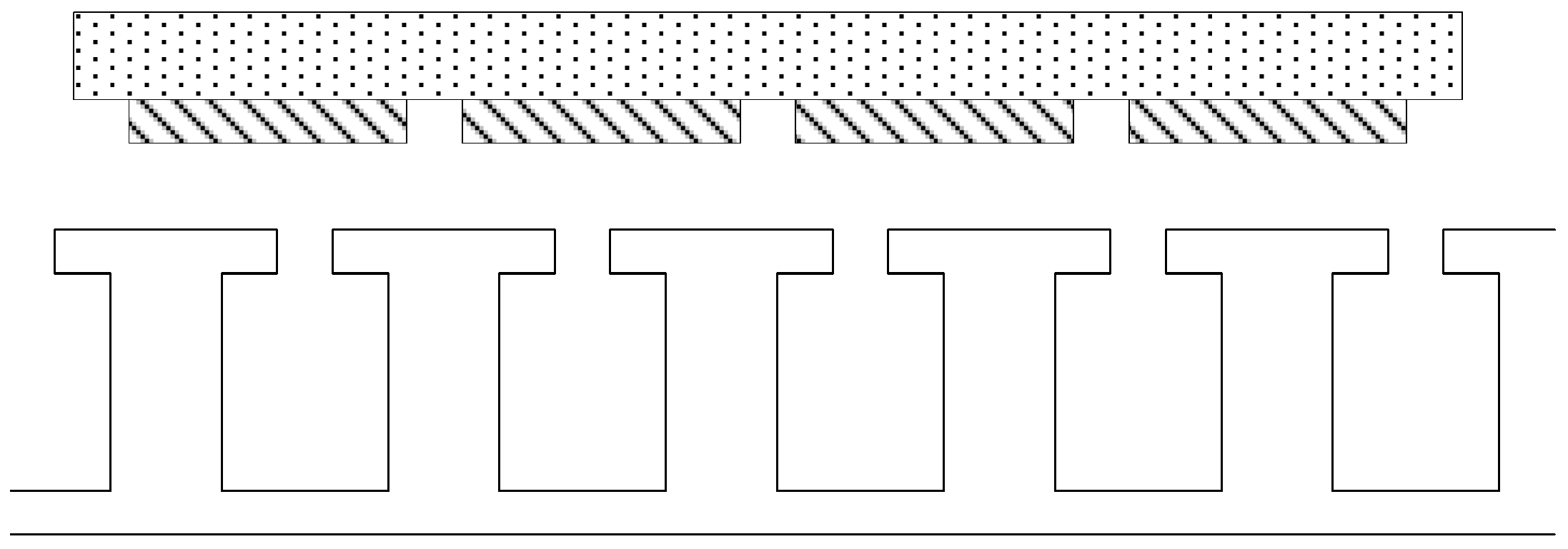
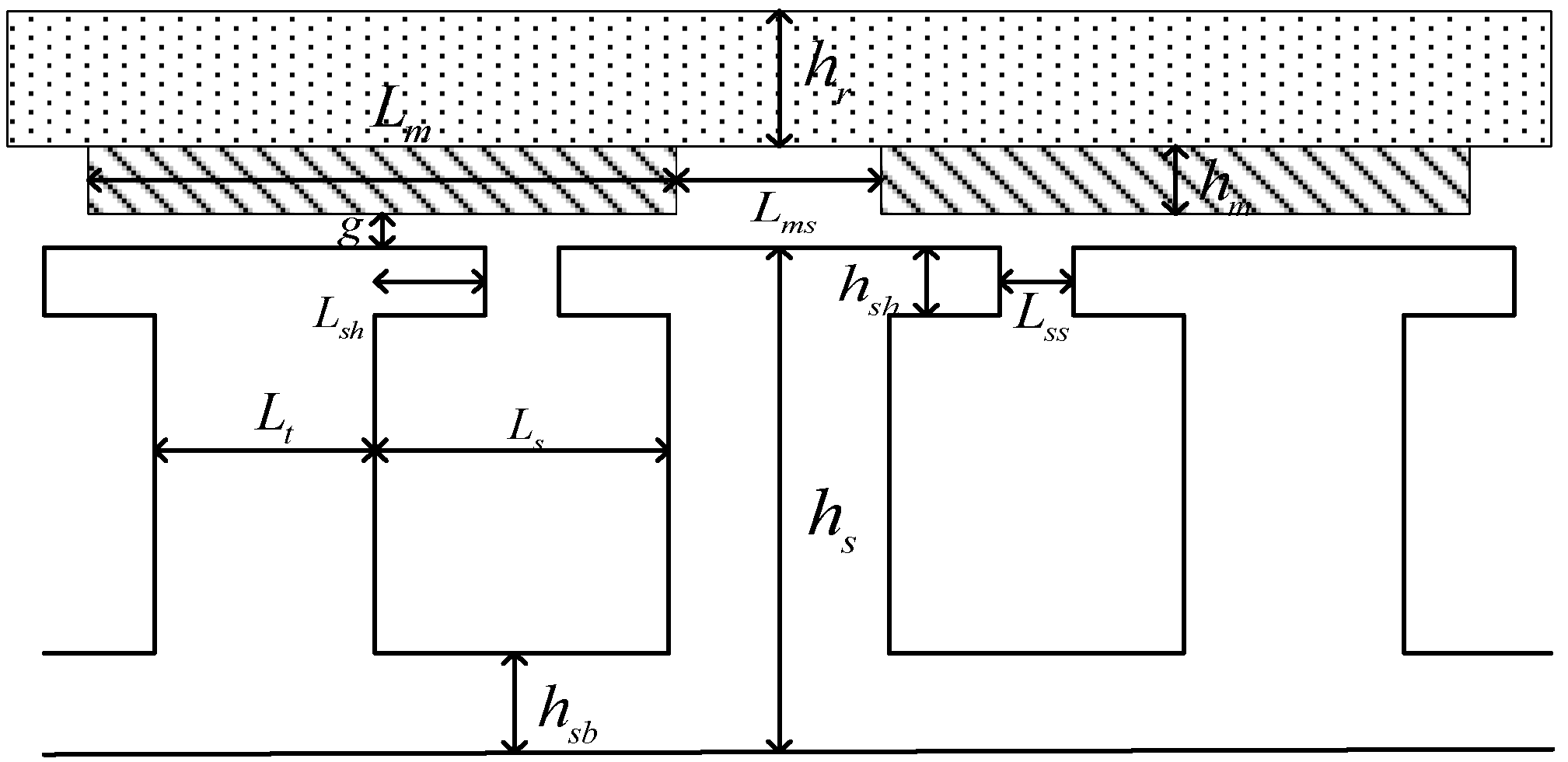
2.1. Motor Model

In this paper, the magnetic equivalent circuit (MEC) method is used to establish the equivalent magnetic circuit model of the permanent magnet motor for theoretical analysis. The motor model is shown in Figure 1. The stator is placed on the inner side, and the permanent magnet poles are arranged alternately according to the N and S polarity and affixed on the surface of the rotor.
The physical meanings represented by the main parameters of the motor are shown in Figure 2.
The exact dimensions and specifications are listed in the Table 1.

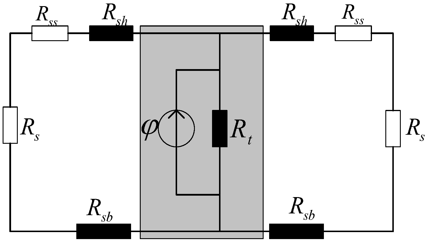
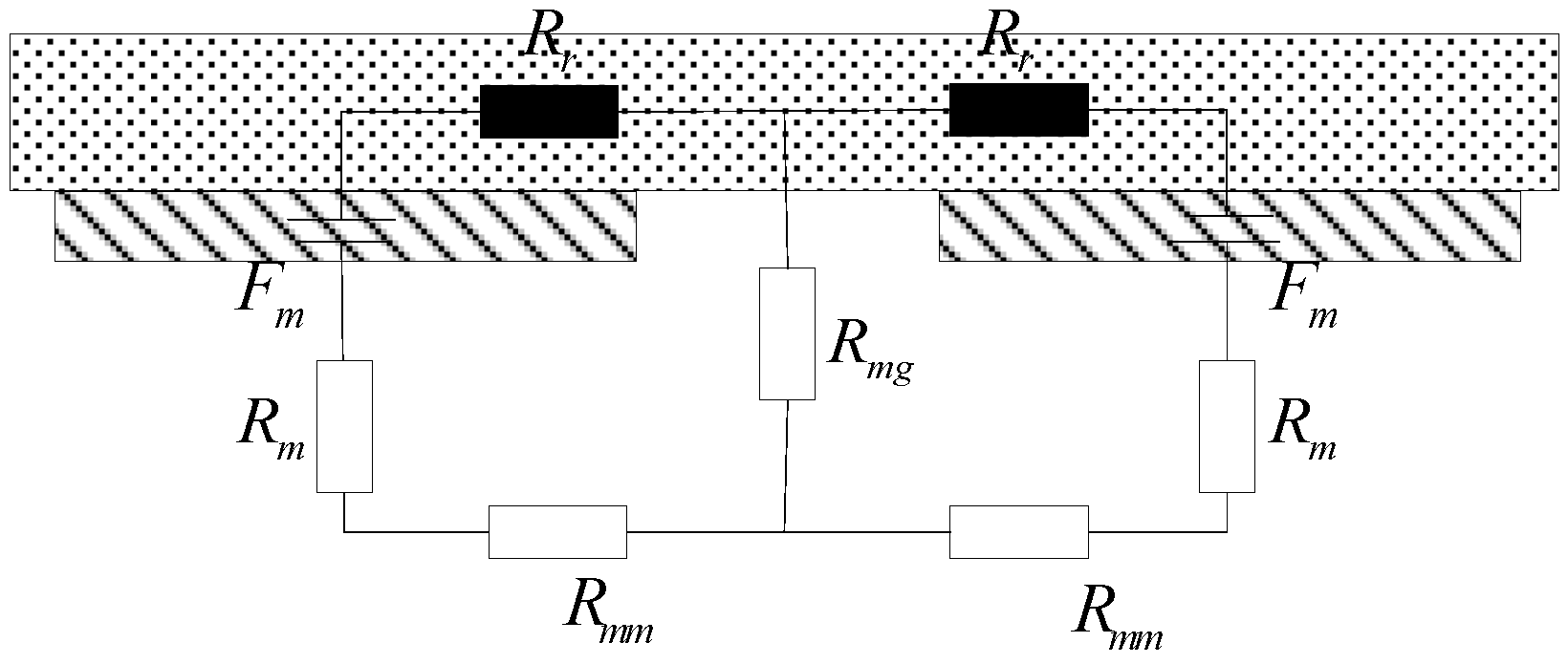
2.2. Magnetic Circuit Modelling

The MEC method will utilize magnetoresistance, which is a change in resistance value with time or position, to perform magnetic circuit calculations, thus enabling highly accurate calculations of magnetic circuit models. In this paper, the nonlinear magnetoresistance is calculated by determining the permeability of the material based on the magnetic field strength at the location of the magnetoresistance to obtain the magnetoresistance and by iterating until the magnetic field strength converges. In order to facilitate the establishment of an equivalent magnetic circuit model, based on the idea of a unitised stator module, the stator yoke is locally analysed in the middle of the two stator slots as shown in Figure 3 in order to establish a single stator module magnetic circuit model. Based on the magnetic circuit model of a single stator module, the permanent magnet magnetic circuit model and the rotor magnetic circuit model discussed later, the entire motor can be modelled as a unitized magnetic circuit.
In this case, the effect of magnetic circuit saturation is represented by nonlinear reluctance R t , R s b and R s h , the leakage flux between the teeth and grooves is represented by reluctance R s and R s s , and the armature response is modelled by φ , with each reluctance calculated from Equations (1)–(5):
R t = h s μ 0 μ r ( B ) L t L a c t
R s h = L s h μ 0 μ r ( B ) h s h L a c t
R s = h s h s h h s b μ 0 L s L a c t
R s s = L s s μ 0 h s h L a c t
R s b = L s 2 μ 0 μ r ( B ) h s b L a c t
where L a c t denotes the effective length of the permanent magnet motor, h s represents the stator radial length, L t represents the stator tooth width, L s h represents the tooth shoulder width, h s h represents the tooth shoulder height, h s b represents the tooth yoke height, L s represents the slot width, L s s represents the notch width.
The process of modelling the equivalent magnetic field of a permanent magnet involves the use of leakage reluctance R m m and R m g , which represent the leakage flux between adjacent permanent magnets and between the permanent magnet and the air gap, respectively [28]. Additionally, it includes the incorporation of the equivalent magnetic potential sources F m and magnetic reluctances R m of the permanent magnet, as shown in Figure 4. Similar to the stator core modelling, the saturation phenomenon of the rotor core is also considered through an iterative process involving nonlinear magnetoresistance R r .
The formulae for each magnetoresistance and magnetic potential are as follows:
F m = H c h m = B r h m μ 0 μ r
R m = h m μ 0 μ r L m L a c t
R m m = π μ 0 L a c t ln ( 1 + π g L m )
R m g = h m μ 0 L m s L a c t
R r = L m + L m s 2 μ 0 μ r ( B ) h r L a c t
where H c denotes the coercivity of permanent magnets, μ r denotes the relative magnetic permeability, B r denotes the residual magnetic flux density, h m denotes the permanent magnet axial length, L m denotes the equivalent width at mean radius, L m s denotes the adjacent permanent magnet spacing.
The nonlinear reluctance in the equivalent magnetic circuit models of the stator and permanent magnets described above needs to be calculated and updated iteratively based on the magnetic field strength.
When deriving the equivalent model of the motor air gap, the relative positions of the permanent magnets and the stator teeth need to be considered, and segmented calculations are carried out according to the differences in the relative positions, which are mainly divided into two segments for illustration: facing the stator slots and facing the stator teeth, as shown in Figure 5.
Assuming that the magnetic flux enters the stator end face only in the radial direction, the reluctance of each individual air gap region can be calculated from Equation (11).
R i = g μ 0 A i
where A i represents the area of the transverse plane perpendicular to the flux path in each individual air gap region.
Based on the equivalent magnetic circuits of the motor components derived in the previous section, the equivalent magnetic circuit model of a pair of poles can be obtained by combining them, and the relevant electromagnetic characteristics of the motor can be solved based on this equivalent magnetic circuit model. Since the magnetic field and structure of the motor are both periodic and symmetric, removing the magnetic circuit model for half a degree cycle gives the magnetic circuit model for the entire degree cycle. By using seven time steps to derive the magnetic circuit model for electrical angles of 0°, 30°, 45°, 60°, 90°, 120°, and 150°, the static characteristics of the motor for the entire electrical degree cycle can be determined based on the period condition. Figure 6 illustrates the equivalent magnetic circuit model of the motor at an electrical angle of 0°. The non-linear reluctance in the figure is represented by the black square, while the white square indicates that the resistance of this reluctance is independent of the magnetic field strength.
Table 2 lists the values obtained by calculating each of the magnetoresistances in Figure 6.
Based on the above model and data, the nodal magnetic potential method is used to solve the magnetic network by analogizing it to a circuit, with the magnetic kinetic potential analogous to voltage, magnetic flux analogous to current, and magnetoresistance analogous to resistance. After converting the magnetic network into an electrical network containing nonlinear resistors, the nonlinear resistors (magnetoresistance) in it need to be iteratively updated and the new values are brought into the network for calculation.
The whole calculation and iteration are realized based on MATLAB R2022a, the calculation process is simple and convenient with strict convergence conditions, and the overall flow is shown in Figure 7.
The discussion and validation of the validity of the magnetic circuit model are discussed and verified in previous research [29]. Figure 2, Figure 3, Figure 4, Figure 5 and Figure 6, and Table 1 and Table 2 first appeared in this article.

3. Loss Analysis

Efficiency is an important indicator to evaluate the performance of a motor, depending on the loss of the motor operation process. In general, the loss of the motor is mainly composed of stator loss P s , rotor loss P r , winding loss P C u , and mechanical loss P m .
Among them, the copper loss P C u not only accounts for the largest proportion, affected by the temperature, but it is also the largest, so it is an important object of concern in this paper, and can be calculated by the following formula:
P C u = m R p h I p h 2
where m , R p h , I p h denote phase number, phase resistance, and phase current respectively.
The stator–rotor core loss is mainly caused by the permanent magnets producing similar trapezoidal wave flux density [30], and the stator core loss is calculated as:
P s = [ k h f B t α + 4 π f 2 B t 2 k e α t ( 2 π β m α t ) + ( 4 π k e x c α t ) 3 4 f 1.5 B t 1.5 ( 2 π β m α t ) 3 4 ] W t +   [ k h f B y α + 8 π f 2 B y 2 k e β m + ( 8 π k e x c β m ) 3 4 f 1.5 B y 1.5 ] W y
where B t , B y , α t , β m , W t , W y , k h , k e , k e x c , α represent the maximum flux density in the stator teeth calculated by the equivalent magnetic circuit model, the maximum flux density in the stator yoke calculated by the equivalent magnetic circuit model, the effective radian angle of the stator teeth, the pole arc of the permanent magnet, the stator teeth weight, the stator yoke weight, the hysteresis loss coefficient, the eddy current loss coefficient, the anomalous loss coefficient, and the calculated coefficients (usually provided by the manufacturer, as determined by the loss data for the soft magnetic composites), respectively.
The rotor core loss is calculated by the formula [31,32]:
P r = 1 2 α R v k z α 2 β 2 ( α s 1 β s 1 k C B a v g μ 0 μ r r e c ) k σ P M S P M + 1 2 α R F e k z α 2 β 2 ( α s 1 β s 1 k C B a v g μ 0 μ r ) k σ F e S F e
where α R v , α R F e , μ r r e c , μ r , σ P M , σ F e , S P M , S F e , α & k , β , α s 1 , β s 1 , k C , B a v g , μ 0 denote permanent magnet reactance coefficient, rotor core reactance coefficient, permanent magnet relative permeability, rotor core relative permeability, permanent magnet conductivity, rotor core conductivity, permanent magnet effective area, rotor core effective area, attenuation coefficient (depends on stator pole pitch), calculation coefficient (depends on stator pole pitch), slot harmonic amplitude, slotting coefficient, Carpenter’s coefficient, average flux density per unit pole pitch, and the vacuum permeability.
In this paper, since P m is mainly generated by friction at the bearings, which are located far away from the stator teeth, windings, rotor, etc., the effect of mechanical losses on the results of the temperature calculations is neglected.
Table 3 gives the values of losses in various parts of the motor calculated using MEC and FEA methods, respectively.
It can be seen from the table that the loss values obtained using different methods have some errors, except for the copper loss. This is due to the fact that the MEC method calculates the magnetic field with a certain error, while the empirical formula calculates the losses with a certain error, which ultimately leads to a large error in the eddy current loss of the permanent magnet part and the loss of the stator teeth without separation.

4. Thermal Network Analysis

4.1. Introduction to the Thermal Network Approach

The equivalent thermal network method, that is, the application of the graph theory principle, will be divided into a number of discrete regions of the motor, the loss of heat source will be concentrated in the discrete regional nodes, the nodes will be connected through the thermal resistance according to the principle of heat transfer to establish a two-dimensional network topology, and then the temperature of the various components of the motor rises for the solution of the method.
When solving the set parameter thermal network for the motor, some preconditions need to be set as follows:
(1)
Set the axis at the centre position of the motor rotor shaft with symmetrical temperature field distribution on both sides;
(2)
Neglect the thermal radiation process of the motor;
(3)
Neglect the skin effect;
(4)
The mutual conductance between two nodes is equal and independent of temperature.

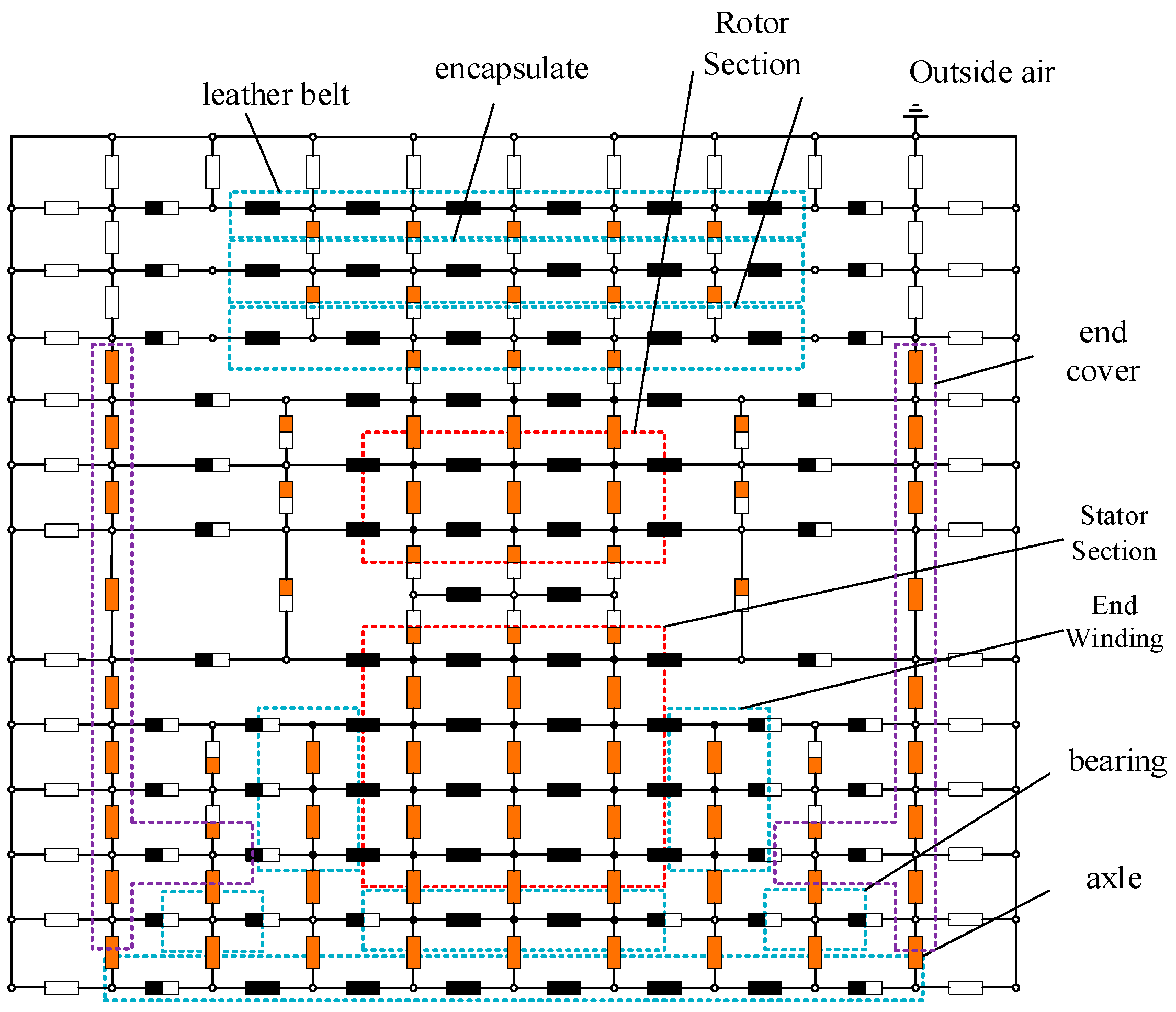
4.2. Thermal Network Modelling

In the thermal network calculation, it is necessary to consider the three heat transfer modes of heat conduction, heat convection and heat radiation, and the motor is divided into different thermal resistance nodes. Figure 8 shows the three-dimensional profile of the outer rotor permanent magnet motor, and the thermal network model is constructed as shown in Figure 9.
The heat transfer mode is mainly by heat conduction and heat convection, while each node is classified into active and passive nodes according to whether there is heat generation or not.
The derivation of the heat balance equation is introduced by taking winding node 26 as an example, where node 26 exchanges heat with nodes 22 (stator teeth), 25 (winding), 27 (winding), and 30 (stator yoke).
  • Calculation of thermal resistance between node 26 and stator tooth node 22
    R 2226 = δ 2226 λ 2226 S 2226
    δ 2226 = δ 1 y + δ 2 y + δ 3 y + δ 4 y
    λ 2226 = δ 2226 i = 1 n δ i y λ i
    S 2226 = 2 ( h s h s h h s b ) Z L 3
    where Z , L , δ i y indicate the number of motor slots, the motor length and the thickness of the copper, guide wires, impregnating varnish and slot insulation in the y-direction, respectively.
2.
Calculation of thermal resistance between node 26 and end winding node 25
R 2526 = L 2526 S 2526 λ C u
L 2526 = L d 4 + L 6
S 2526 = π 4 d w 2 Z N
where L d , d w , N represent winding end projection, winding radius, and number of conductors per slot, respectively.
3.
Calculation of thermal resistance between node 26 and slot winding node 27
R 2627 = L 3 S 2627 λ C u
S 2627 = S 2526
4.
Calculation of thermal resistance between node 26 and stator yoke node 30
R 2630 = δ 2630 λ 2630 S 2630 + h s b 2 S 2630 λ R
δ 2630 = δ 1 x + δ 2 x + δ 3 x + δ 4 x
λ 2630 = δ 2630 i = 1 n δ i x λ i
S 2630 = L s Z L 3
where δ i x are the thicknesses of copper, conductor wire, impregnating varnish and slot insulation along the x-direction, respectively.
G 2626 = G 2622 + G 2627 + G 2625 + G 2630 G 2626 T 26 G 2622 T 22 G 2625 T 25 G 2627 T 27 G 2630 T 30 = W 26 W 26 = P C u 3
On the basis of the thermal network model mentioned above, due to the larger size of the stator and rotor parts of the motor studied in this paper, as well as the fact that the temperatures of these two parts are inherently more important to be concerned about, a finer thermal network model is developed for the stator and rotor parts to obtain more accurate temperature distribution results. The multilayer thermal resistance thermal network model of the stator part is shown in Figure 10. The multilayer thermal resistance thermal network model of the rotor part is shown in Figure 11. In these two figures, the grey rectangles indicate the lateral conduction thermal resistance, the orange rectangles indicate the radial conduction thermal resistance, and the two-colour rectangles indicate the conduction thermal resistance of the corresponding composite structure. Among them, the black solid circle in the thermal network indicates a lossy heat source, and the hollow circle indicates no heat source. For the convenience of presentation and calculation, only one forty-eighth of the model is modelled in this paper, and the rest is consistent with the model.
Based on the preliminary thermal network model given in Figure 9, the complete three-dimensional thermal network schematic for the multilayer thermal resistance division of large-size materials is given in this paper, as shown in Figure 12. The equivalent thermal network models of the stator part and rotor distribution are simplified for ease of understanding, and only one temperature node and one thermogravimetric resistor are used to represent the thermal network models of the stator part and rotor part, and the simplified equivalent thermal network models of the stator part and rotor part are marked with red dashed lines. The other parts of the generator are labelled with blue or purple dashed boxes. In the figure, the black rectangles indicate the axial conduction thermal resistance, the orange rectangles indicate the radial conduction thermal resistance, the two-coloured rectangles indicate the mixed conduction thermal resistance in the corresponding directions, and the blank rectangles indicate the convection thermal resistance. In the same way as the representation of the temperature nodes of the stator part of the thermal network model, the black solid circles indicate the nodes with lossy heat sources, and the hollow circles indicate the nodes without lossy heat sources.
The thermal coefficients of the materials for each part of the motor in this paper are presented in Table 4.

4.3. Heat Balance Equation

The heat balance matrix is created from the heat balance equations at each point as shown below:
G ( i , 1 ) T ( 1 ) G ( i , 2 ) T ( 2 ) + G ( i , i ) T ( i ) G ( i , i + 1 ) T ( i + 1 ) G ( i , n ) T ( n ) = P ( i )
where G ( i , i ) denotes self-conductors at each node, G ( i , j ) is mutual derivatives of each node, P ( i ) is node loss and T ( i ) indicates temperature rise of nodes.

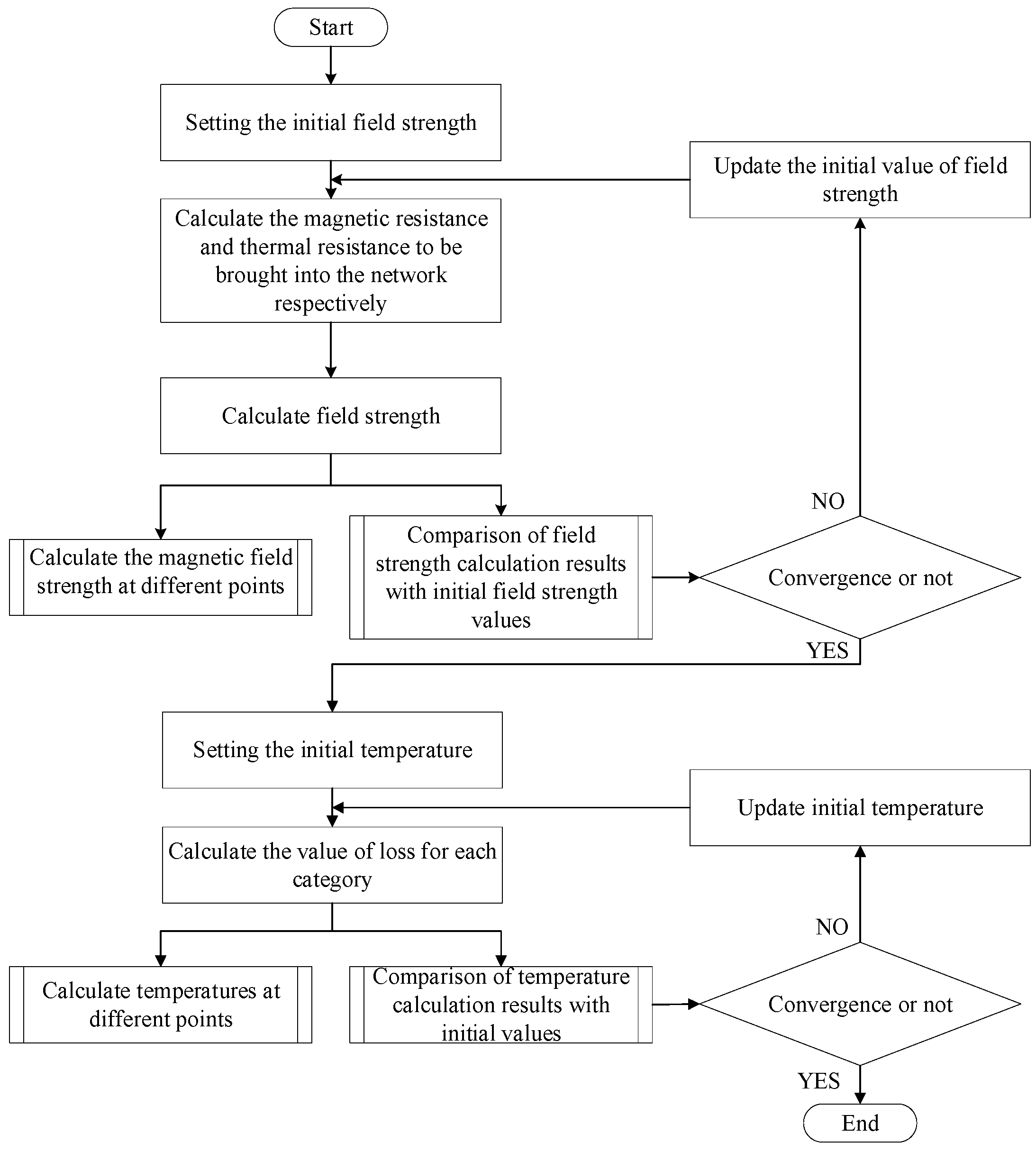
5. Calculation Method

In this paper, by writing a program to calculate the initial value of the magnetic circuit and loss and then calculate the initial value of the magnetic field and temperature field, the results of the temperature field are substituted into the secondary calculation of the magnetic circuit and loss, which results in a new magnetic field and loss, the secondary calculation of the temperature field, and so on, iteratively calculated to obtain the final convergence value. At the same time, the values of each parameter of the motor can be changed according to the needs, representing greater flexibility.
As copper consumption generally accounts for a large proportion of all losses, only considering the effect of temperature on the copper consumption of the calculation results also has a certain degree of accuracy, according to whether or not the difference between the magnetic and thermal characteristics of the permanent magnets is taken into account. This paper is divided into two types of calculation process, respectively: only considering the effect of temperature on the winding resistance, and the full consideration of the temperature on the performance of the permanent magnets, the copper resistance, and the achievement of the rated output of the required current rating. The effect of temperature on the performance of the permanent magnet, copper resistance, and the rated current is required to achieve the rated output.

5.1. Considering Only the Effect of Temperature on Copper Consumption

According to Equation (12), the copper resistance and current mainly determine the copper consumption, while the copper resistance varies by temperature, which can be calculated by Equation (30).
R t = R 0 235 + T t 235 + T 0
where R 0 , T 0 is the initial resistance and initial temperature.
The overall computational flow is shown in Figure 13.

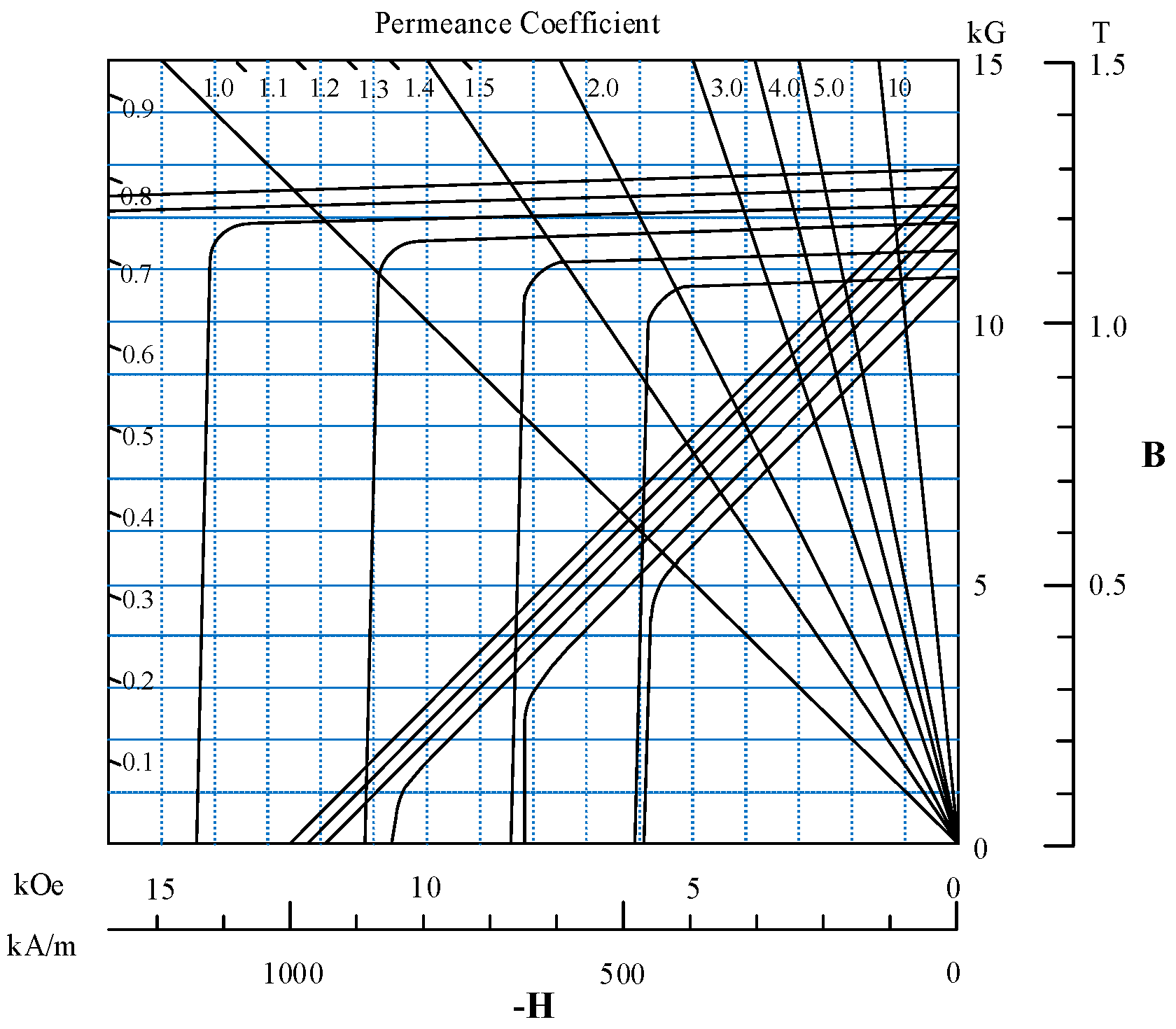
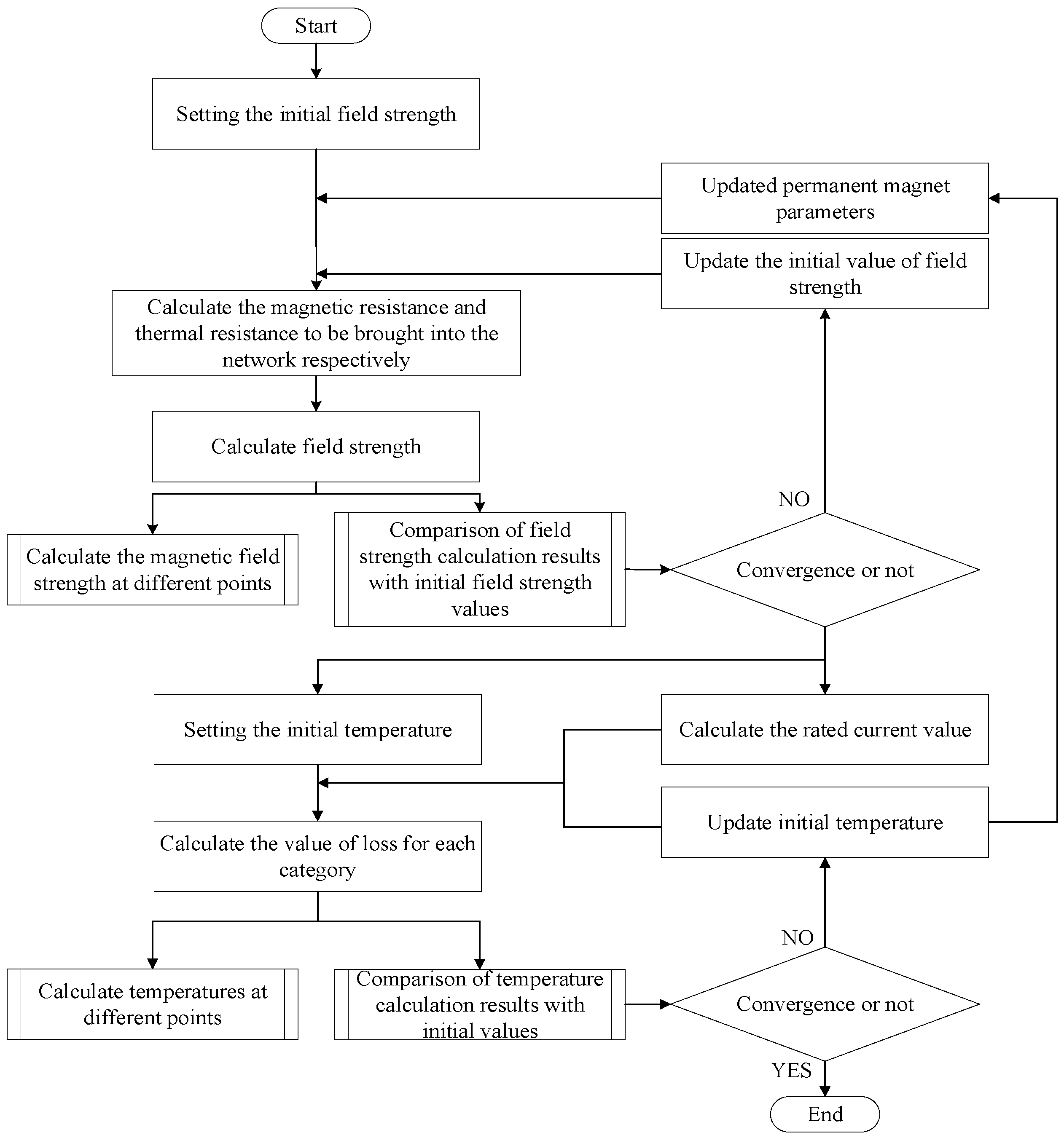
5.2. Consider the Effect of Temperature on the Performance of Permanent Magnets

The remanent magnetization and coercivity of a permanent magnet is an important index for evaluating the working performance of the permanent magnet. In the temperature field calculation, the maximum temperature of the permanent magnet is usually considered not to be greater than the demagnetization temperature of permanent magnet material. In this paper, we select the N42SH material (Shin-Etsu Chemical Industry Co., Tokyo, Japan), which is relatively poor in heat-resistant ability, and its demagnetization curve with temperature is shown in Figure 14, and the degree of remanent magnetization and coercivity affected by temperature is calculated using the temperature coefficients, which are −0.11 (%/°C) and −0.52 (%/°C), respectively.
According to Equations (13) and (14), the change in permanent magnet performance leads to a change in field strength, which in turn affects the value of iron consumption and updating the calculation parameters for recalculation is required. The change in rated current, on the other hand, can be calculated from Equation (31).
I s = 2 T r 3 p N k ω Φ m
where p is the number of pole pairs, k ω is the winding factor, Φ m is the magnetic flux per pole of the permanent magnet, T r is the rated torque.
The overall computational flow is shown in Figure 15.

6. Validation of Results

The calculation results of the thermal network method are shown in Figure 16 and Figure 17, which are the calculation results of only considering the temperature effect on copper resistance and considering the temperature effect on permanent magnet performance, respectively, and only the results of the stator–rotor and windings and other important parts are shown for the convenience of comparison.
For the magnetic–thermal coupling calculation method of MEC + LPTN proposed in this paper, the magnetic–thermal coupling calculation based on finite elements is performed to compare and validate the method.
The results of the FEA calculations are shown in Figure 18 and Figure 19. In these two figures, a, b, c, d are the results of the temperature field calculations for the stator part, per manent magnet, winding, and enclosure, respectively.
The results of the thermal network calculations are compared with those of the finite element calculations, respectively, as shown in Table 5.
From the table, it can be seen that there is a certain error in the calculation results of the two methods, in which the error of the rotor part and the casing is more than 5%.
The calculation error in the rotor section is mainly due to the fact that when considering the influence of the temperature rise on the performance of the permanent magnets in the calculation results, there is a certain error in the magnetic field strength itself calculated by the MEC method, and at the same time, the loss data are calculated according to empirical formulas, and therefore the results of the temperature rise of the permanent magnets and the rotor part have a large error.
The reason for the error at the enclosure is that, in addition to the error in the calculation of the rotor loss value, the heat dissipation of the casing is more complicated and fewer points are selected in the calculation process, which leads to a larger error in the calculation results of this part. The stator part is more critical due to the influence of copper loss, so the accuracy of the calculation results is basically unaffected.
The error of the calculation results is within the permissible range, and the calculation results are valid.
By analysing the calculation error, the calculation accuracy of the loss value will affect the calculation result of the temperature field, and to obtain a more accurate loss value, the magnetic circuit model or the empirical formula can be improved. Improvements to the magnetic circuit model include a more detailed division of the magnetoresistance or the derivation of the model at more electrical angles. Improvements to the empirical formulas require a more detailed study of the theory.
Through the comparison and analysis of the calculation results, whether or not to consider the effect of temperature rise on the performance of permanent magnets also has a greater impact on the final temperature rise results, so it is necessary to consider the thermal performance of permanent magnets in the thermal calculations for the safe operation of the motor, and the method proposed in this paper can be quickly calculated for this process.

7. Conclusions

In this paper, based on the magnetic circuit structure considering magnetic saturation and magnetic leakage, we analyze and calculate the relevant losses of the permanent magnet motor, build a more accurate thermal network model for thermal calculation of the research motor that considers whether the temperature affects the working performance of permanent magnets, respectively, and verify the results of the thermal network calculations by comparing the results with those of the finite element calculations, which verifies the validity of the model and the calculating method in two different situations. The validity of the model and calculation method in two different cases is verified, and based on the calculation results, it is proposed that it is necessary to consider the effect of temperature on the working performance of permanent magnets for thermal calculation when designing the motor. The calculation method proposed in this paper couples the electromagnetic field with the thermal field in the theoretical calculation, which well balances the relationship between the calculation accuracy and the speed, and greatly improves the calculation efficiency compared with the finite element, so that the performance of the motor can be quickly analyzed by the magnetic–thermal coupling, which is able to provide guidance for the overall design of the motor.

Author Contributions

Conceptualization, Z.X., Y.W., L.J., H.Z. and J.H.; methodology, Z.X., Y.W., L.J., H.Z. and J.H.; software, Y.W.; validation, Y.W., H.Z. and J.H.; formal analysis, Y.W.; investigation, Y.W.; resources, H.Z.; data curation, J.H.; writing—original draft preparation, Y.W.; writing—review and editing, Z.X. and Y.W.; visualization, Y.W.; supervision, Z.X.; project administration, Z.X. All authors have read and agreed to the published version of the manuscript.

Funding

This research received no external funding.

Data Availability Statement

The original contributions presented in this study are included in the article. Further inquiries can be directed to the corresponding author.

Conflicts of Interest

The authors declare no conflict of interest.

References

  1. Zhang, G.; Zhang, B. Analysis of torque characteristics of ultra-low speed and large torque permanent magnet motor for cement mill. Electr. Eng. 2021, 15, 188–191. [Google Scholar]
  2. Li, W.; Zhang, W.; Feng, B.; Feng, G. Design of Low-speed direct-drive external rotor permanent magnet synchronous motor. Micro Mot. 2022, 55, 24–29+51. [Google Scholar]
  3. Shen, M.; Pfister, P.; Tang, C.; Fang, Y. A hybrid model of permanent-magnet machines combining Fourier analytical model with finite element method, taking magnetic saturation into account. IEEE Trans. Magn. 2021, 57, 7400105. [Google Scholar] [CrossRef]
  4. Tang, C.; Shen, M.; Fang, Y.; Pfister, P. Comparison of subdomain, complex permeance and relative permeance models for a wide family of permanent-magnet machines. IEEE Trans. Magn. 2020, 57, 8101205. [Google Scholar] [CrossRef]
  5. Ju, Y.; Xu, Z.; Zhang, D.; Shi, Y. Study on the number of slot poles and rotor magnetic circuit structure based on 12-slot 10-pole permanent magnet motor. Small Spec. Electr. Mach. 2021, 49, 11–14. [Google Scholar]
  6. Li, L.; Huang, X.; Kou, B.; Pan, D. Numerical calculation of temperature field of cylindrical linear motor based on finite element method. Trans. China Electrotech. Soc. 2013, 28, 132–138. [Google Scholar]
  7. Zhu, Y.-W.; Lee, S.-G.; Chung, K.-S.; Cho, Y.-H. Investigation of auxiliary poles design criteria on reduction of end effect of detent force for PMLSM. IEEE Trans. Magn. 2009, 45, 2863–2866. [Google Scholar] [CrossRef]
  8. Sun, Y.; Wu, J.; Xiang, Q. Mathematical model of magnetic levitation switched reluctance motor based on finite element method. Proc. CSEE 2007, 27, 32–40. [Google Scholar]
  9. Li, G.; Song, S.; Li, H. Characterization of permanent magnet synchronous motor based on equivalent magnetic circuit method. Small Spec. Electr. Mach. 2016, 44, 54–57. [Google Scholar]
  10. An, L.; Wang, C.; Li, C.; Jang, M.; Deng, Y. Aerospace permanent magnetic synchronous motor design and simulation based on magnetic circuit method and equivalent thermal network method. Astronaut. Syst. Eng. Technol. 2022, 6, 44–49. [Google Scholar]
  11. He, J.; Yang, J.; Zhao, Q.; Li, Y.; Zhen, W. Magnetic circuit model of internal magnet voice coil motors considering edge flux. Small Spec. Electr. Mach. 2021, 49, 17–22. [Google Scholar]
  12. Fan, Y.; Wen, X. Simulation calculation of three-dimensional temperature field of hydro generator stator. Power Syst. Eng. 2006, 2, 51–52, 60. [Google Scholar]
  13. Wei, X.; Yao, B.; Wang, Z.; Zhang, Y.; Peng, Y.; Sun, Y.; Wang, K.; Wang, H. A robust online junction temperature calibration method for power semiconductors in traction inverter application. IEEE Trans. Transp. Electrif. 2024, 11, 6602–6614. [Google Scholar] [CrossRef]
  14. Wei, X. Temperature Field Analysis of Permanent Magnet Synchronous Motor and Research on Cooling System. Ph.D. Thesis, Xiangtan University, Xiangtan, China, 2017. [Google Scholar]
  15. Wu, J.; Zhang, B. Temperature field study of external rotor permanent magnet synchronous motors for belt conveyors. Explos.-Proof Electr. Mach. 2020, 22, 8–12, 31. [Google Scholar]
  16. Xia, W. Design of water-cooling system for mining explosion-proof permanent magnet synchronous motor. New Technol. New Prod. China 2020, 3, 25–26. [Google Scholar]
  17. Wang, W.; Chen, Y. Thermal circuit analysis and thermal resistance parameter testing of permanent magnet synchronous motors. Mechatron. Eng. 2014, 31, 1168–1172. [Google Scholar]
  18. Fu, Y. Temperature Field Analysis of Permanent Magnet Synchronous Motor for Electric Cars. Master’s Thesis, Liaoning University of Technology, Jinzhou, China, 2014. [Google Scholar]
  19. Deaconu, A.S. Permanent magnet synchronous motor thermal analysis. In Proceedings of the 6th IET International Conference on Power Electronics, Machines and Drives, Bristol, UK, 27–29 March 2012; pp. 1–5. [Google Scholar]
  20. Joo, D. Electromagnetic Field and Thermal Linked Analysis of Interior Permanent-Magnet Synchronous Motor for Agricultural Electric Vehicle. IEEE Trans. Magn. 2011, 7, 4242–4245. [Google Scholar] [CrossRef]
  21. Nategh, S.; Zhang, H.; Wallmark, O. Transient Thermal Modeling and Analysis of Railway Traction Motors. IEEE Trans. Ind. Electron. 2019, 66, 79–89. [Google Scholar] [CrossRef]
  22. Wall, S.O.; Bocker, J. Global identification of a Low-Order Lumped-Parameter thermal network for permanent magnet synchronous motors. IEEE Trans. Energy Convers. 2016, 31, 354–365. [Google Scholar]
  23. Wang, R.J.; Heyns, G.C. Thermal analysis of a water-cooled interior permanent magnet traction machine. In Proceedings of the 2013 IEEE International Conference on Industrial Technology (ICIT), Cape Town, South Africa, 25–28 February 2013; pp. 416–421. [Google Scholar]
  24. Qiu, H.; Tang, B.; Wang, R.; Zhan, G.; Yang, C.X.; Cui, G. Optimization and Calculation of Equivalent Thermal Network Method in the Temperature Field Research of Permanent Magnet Servo Motor. Recent Adv. Electr. Electron. Eng. 2016, 9, 241–248. [Google Scholar]
  25. Ding, F.; Wang, A.; Zhang, Q. Analysis of unidirectional and bidirectional magnetic-thermal coupling of permanent magnet synchronous motor. J. Vibroengineering 2022, 24, 1541–1555. [Google Scholar] [CrossRef]
  26. Wang, J.; Cheng, M.; Qin, W.; Liu, Q. Fast Calculation Method of Bi-Direction Coupling Between Electromagnetic-Thermal Field for FSPM Motor. IEEE Trans. Magn. 2023, 59, 8205909. [Google Scholar] [CrossRef]
  27. Tan, L.; Zhou, Y.; Xiao, W. Magnetic-Thermal-Fluid Field Coupling Method Study on Temperature Rise Analysis of Permanent Magnet Motor. In Proceedings of the International Petroleum and Petrochemical Technology Conference, Shanghai, China, 25–27 August 2021; pp. 223–232. [Google Scholar]
  28. Qu, R.; Lipo, T.A. Analysis and modeling of air-gap and zigzag leakage fluxes in a surface-mounted permanent-magnet machine. IEEE Trans. Ind. Appl. 2004, 40, 121–127. [Google Scholar] [CrossRef]
  29. Wang, Y.; Xu, Z.; Jin, L.; Zhang, H.; Hong, J. Magnetic Equivalent Circuit Modeling of Permanent Magnet Synchronous Motor with External Rotor. Front. Acad. Forum Electr. Eng. 2025, 1287, 659–668. [Google Scholar]
  30. Deng, F. An improved iron loss estimation for permanent magnet brushless machines. IEEE Trans. Energy Convers. 1999, 14, 1391–1395. [Google Scholar] [CrossRef]
  31. Gieras, J.; Wang, R.; Kamper, M. Axial Flux Permanent Magnet Brushless Machines; Springer Science & Business Media: Berlin/Heidelberg, Germany, 2008. [Google Scholar]
  32. Li, J.; Choi, D.; Cho, C.; Koo, D.H.; Cho, Y.H. Eddy-current calculation of solid components in fractional slot axial flux permanent magnet synchronous machines. IEEE Trans. Magn. 2011, 47, 4254–4257. [Google Scholar] [CrossRef]
Figure 1. Schematic structure of the studied motor.
Energies 18 01891 g001
Figure 2. Schematic diagram of the main parameters of the studied motor.
Energies 18 01891 g002
Figure 3. Magnetic equivalent circuit model of a single stator tooth module.
Energies 18 01891 g003
Figure 4. The magnetic equivalent circuit model of the permanent magnet and rotor core.
Energies 18 01891 g004
Figure 5. Schematic diagram of air-gap magnetic circuit.
Energies 18 01891 g005
Figure 6. The complete magnetic equivalent model for the studied electromechanical electrodynamic angle of 0 degrees.
Energies 18 01891 g006
Figure 7. Calculation process of the MEC model.
Energies 18 01891 g007
Figure 8. Outer rotor permanent magnet motor sectional view.
Energies 18 01891 g008
Figure 9. Thermal network (thermal node) model for external rotor motors.
Energies 18 01891 g009
Figure 10. Multilayer thermal network modelling of stator section with thermal resistance.
Energies 18 01891 g010
Figure 11. Multilayer thermal network modelling of rotor section with thermal resistance.
Energies 18 01891 g011
Figure 12. Schematic diagram of three-dimensional thermal network divided by multilayer thermal resistance of an external rotor motor at steady state.
Energies 18 01891 g012
Figure 13. Flowchart of the calculation when only the effect of temperature on copper resistance is considered.
Energies 18 01891 g013
Figure 14. Demagnetization curve of N42SH (variation with temperature).
Energies 18 01891 g014
Figure 15. Flowchart of the calculation when considering the effect of temperature on the performance of permanent magnets.
Energies 18 01891 g015
Figure 16. Thermal network calculation results when only considering the effect of temperature on copper resistance.
Energies 18 01891 g016
Figure 17. Thermal network calculation results when considering the effect of temperature on the performance of permanent magnets.
Energies 18 01891 g017
Figure 18. FEA calculation results when only considering the effect of temperature on copper resistance.
Energies 18 01891 g018
Figure 19. FEA calculation results when considering the effect of temperature on the performance of permanent magnets.
Energies 18 01891 g019
Table 1. Dimensions and specifications of the studied machine.
ParameterSymbolValueUnit
Rated powerP131kW
Rated voltageU806V
Stator outer diameterDo734mm
Stator inner diameterDi460mm
Air gap lengthg1.5mm
Stator axial heighths137mm
Rotor axial heighthr23mm
Magnet heighthm9mm
Magnet pole arc ratio-0.8
Slot widthLs28.8mm
Shoe widthLss9.6mm
Stator shoulder heighthsh8mm
Stator shoulder widthLsh9.6mm
Stator yoke heighthsb43mm
Stator tooth widthLt19.2mm
Table 2. The calculated values of resistance.
SymbolValue (μH−1)
Rm0.18
Rmg0.97
Rrvaried
Rmm8.14
Rs2.80
Rtvaried
Rsbvaried
Rshvaried
Rss1.24
R10.32
R20.11
R30.16
R40.16
R50.16
R60.32
R70.16
Table 3. Comparison of calculated loss values for each part of the motor at 20 °C.
Areas of MotorMECFEAError/%
Stator yoke/W1332.21273.64.6
Stator teeth/W345.1323.46.7
Winding/W3149.23149.20
Permanent magnet/W237.5224.95.6
Rotor/W845.1813.43.9
Table 4. Thermal conductivity of materials for each part of the motor.
SectionX Thermal Conductivity
(W/m·K)
Y Thermal Conductivity
(W/m·K)
Z Thermal Conductivity
(W/m·K)
Density
(kg/m3)
DW47539394.437800
Winding3853853858900
Winding insulation0.260.260.26200
Permanent magnet9997400
End Cavity Air0.03050.03050.03051.005
Enclosure2102102107800
Encapsulate0.240.240.241.15
Leather belt0.170.170.171400
End cover3939397800
Axle4343437800
Bearing1818187800
Table 5. Validation of results.
Average TemperatureLPTN 1FEA 1Error/%LPTN 2FEA 2Error/%
Stator yoke/°C68.4663.682.779.54
Stator teeth/°C68.866.2483.179.74.3
Winding/°C68.666.43.383803.8
Permanent magnet/°C68.365.34.482.978.55.6
Enclosure/°C62.958.47.774.969.47.9
Where 1 is the effect of temperature on the copper resistance only, and 2 takes into account the effect of temperature on the performance of the permanent magnets.
Disclaimer/Publisher’s Note: The statements, opinions and data contained in all publications are solely those of the individual author(s) and contributor(s) and not of MDPI and/or the editor(s). MDPI and/or the editor(s) disclaim responsibility for any injury to people or property resulting from any ideas, methods, instructions or products referred to in the content.

