Article

Design of an Efficient MPPT Topology Based on a Grey Wolf Optimizer-Particle Swarm Optimization (GWO-PSO) Algorithm for a Grid-Tied Solar Inverter Under Variable Rapid-Change Irradiance

by
Salah Abbas Taha
1,*,
Zuhair S. Al-Sagar
2,
Mohammed Abdulla Abdulsada
1,
Mohammed Alruwaili
3,* and
Moustafa Ahmed Ibrahim
4,*
1
Electrical Engineering Technical College, Middle Technical University, Baghdad 10074, Iraq
2
Department of Renewable Energy Techniques, Middle Technical University, Baghdad 10074, Iraq
3
Department of Electrical Engineering, College of Engineering, Northern Border University, Arar 91431, Saudi Arabia
4
Electrical Engineering Department, University of Business and Technology, Jeddah 23435, Saudi Arabia
*
Authors to whom correspondence should be addressed.
Energies 2025, 18(8), 1997; https://doi.org/10.3390/en18081997
Submission received: 12 March 2025 / Revised: 7 April 2025 / Accepted: 10 April 2025 / Published: 13 April 2025
(This article belongs to the Section F: Electrical Engineering)

Abstract

:
A grid-tied inverter needs excellent maximum power point tracking (MPPT) topology to extract the maximum energy from PV panels regarding energy creation. An efficient MPPT ensures that grid codes are met, maintains power quality and system reliability, minimizes power losses, and suppresses rapid response to power fluctuations due to solar irradiance. Moreover, appropriate MPPT enhances economic returns by increasing energy royalties and ensures high power quality with reduced harmonic distortion. For these reasons, an improved hybrid MPPT technique for a grid-tied solar system is presented based on particle swarm optimization (PSO) and grey wolf optimizer (GWO-PSO) to achieve these objectives. The proposed method is tested under MATLAB/Simulink 2024a for a 100 kW PV array connected with a boost converter to link with a voltage source converter (VSC). The simulation results show that the proposed GWO-PSO can reduce the overshoot on rise time along with settling time, meaning less time is wasted within the grid power system. Moreover, the suggested method is compared with PSO, GWO, and horse herd optimization (HHO) under different weather conditions. The results show that the other algorithms respond more slowly and exhibit higher overshoot, which can be counterproductive. These comparisons validate the proposed method as more accurate, demonstrating that it can enhance the real power quality that is transferred to the grid.

1. Introduction

Currently, photovoltaic (PV) systems are seeing usage growth as one of the most rapidly emerging technologies in renewable energy. As an important contributor to global energy supply, the relevance of solar energy systems is growing since they use semiconductor materials to transform solar energy directly into electricity [1]. In this manner, renewable energy and environmental protection merge into a single phenomenon. As components of the solar energy technology, these PV systems greatly help in controlling the emission of greenhouse gases as well as in curbing global warming [2]. Unlike fossil fuels, solar energy is globally available, inexhaustible, and abundant. Therefore, both grid and stand-alone systems can utilize PV systems, especially in remote areas with inadequate energy infrastructure. There has been increased adoption of PV systems owing to improved technology, lower costs, and supportive government policies [3].
However, to enhance the efficacy of PV systems’ solar energy conversion, usage of Maximum Power Point Tracking (MPPT) is necessary. The power output from solar panels varies with both sunlight intensity and temperature changes [4,5]. MPPT algorithms make certain that a PV system continuously operates at its optimal power point by tracking sunlight and autonomously adjusting the load to extract as much energy as possible. With the implementation of MPPT, PV systems perform with higher efficiency and decreased energy losses, which makes them more reliable and economical for green energy production. Some of the traditional MPPT techniques, like Perturb and Observe (P&O) and Incremental Conductance (INC), are used widely because of their effectiveness and simplicity in implementation [6,7,8]. These methods, however, face obstacles such as slow tracking speed, steady-state oscillations, and low efficiency in rapidly changing environments. In response to this challenge, the most recent studies adopted optimization MPPT strategies which, as the name suggests, incorporate an optimization algorithm [9,10]. These processes are modelled after natural phenomena and possess one form of artificial intelligence, allowing for complex and flexible solutions to changing environmental conditions [11,12,13]. Some widely used optimization MPPT algorithms are: Particle Swarm Optimization (PSO), Genetic Algorithms (GAs), Grey Wolf Optimizer (GWO), and Horse Herd optimization (HHO) [14,15,16,17]. These have outperformed traditional approaches by accelerating convergence speeds, improving accuracy and increasing stability. In addition, these algorithms enable MPPT in PV systems to function with enhanced power efficiency, as it allows a shifting of the operating point with virtually no loss of power.
There are many studies presented in the literature in field of PV MPPT methods [18,19,20,21,22]. In [18], a hybrid PSO-INC method for solar PV array was introduced in order to improve the performance and the speed of the tracking MPP. The goal was to improve the performance of PV systems in a variety of environmental settings. This method speeds up the process of updating the PSO filter’s velocity and uses natural selection for adaptive particle filtration. The hybrid approach does so by incorporating INC, which is well-known for its rapid convergence. Simulation results show that the studied algorithm exhibits sustained output at 99.9% efficiency under static partial shading conditions. The PSO-INC algorithm exhibits a 68.18% increase in convergence rates compared to conventional PSO and greater stability than traditional INC, resulting in more reliable performance. It works better when the amount of light is changing, too. Compared to traditional PSO, the algorithm achieves a 93.33% faster convergence speed, and it quickly adjusts to changing conditions to keep expanding. It has been proven by more experiments that PSO-INC has the shortest steady-state time and a convergence speed that is 85.52% faster than conventional PSO. In [19], the authors proposed a new MPPT method via INC that combines the GWO algorithm with the Levy flight function, which incorporates the PV system MPPT control strategy. With GWO, PV systems first see the global optimum and then track to the nearby optimal. As compared to GWO, INC, and ICS-P&O algorithms, the non-steady state has cut the average tracking time by 0.021 s, making it about 20.53% faster than other methods. Puzzle tracking reliability is now over 99%. There are fewer oscillations and a more stable voltage output. The authors in [20] proposed some advanced hybrid MPPT methods to increase the efficiency and enhance the performance. The PV water pumping system presented in this paper revolves around the control strategies for the MPPT. Some of them include P&O-PI and fuzzy-PI controllers optimized for genetic and particle swarm algorithms. There is also a second-order controller designed to work with a non-linear plant. The simulation results for the different methods are shown and talked about in order to compare how well the FL-PI controller optimized by PSO worked with the other methods in terms of productivity, stability, efficiency, and all of these combined when the system is running at a steady state. In [21], the authors developed an adaptation of a zebra optimizing algorithm (ZOA) for an MPPT controller using an adaptive neural fuzzy interface system (ANFIS) in order to optimize the solar and wind energy systems. The ANFIS controller captures the maximum power from the solar panels and wind turbines. The implemented power flow management (PFM) model is created in MATLAB/Simulink and has three different cases of operation in order to analyze the efficiency of various standby system configurations in different operating scenarios.
The system works at optimal performance due to the problems and goals, which ensures that power can be generated and, at the same time, load requirements can be effectively generated by utilizing the proposed PFM strategy.
In [22], the authors propose a new approach MPPT using a hybrid GWO–PSO technique to overcome the partial shading challenge. The new MPPT technique not only eliminates the problems with previous attempts at MPPT, such as P&O or INC attempts, but it also gives PV systems an effective method to deal with partial shading. The efficiency of other methods of execution of the technique is also addressed with the step MPPT technique. The integration of GWO-PSO appears to be robust, and its capability does not depend upon the mid and maximum power output aimed at the estimated position of GMPP. The feasibility and effectiveness of the design were validated by computer simulations employing MATLAB/SIMULINK and PSIM programs. The simulation results conducted under changing environmental conditions were expected in regard to the effectiveness of the hybrid MPPT method. A hybrid model that incorporates both IGWO and P&O is introduced in [23]. It was seen in the simulations that the IGWO-P&O hybrid MPPT algorithm can improve MPPT speed and accuracy while also lowering oscillation power. Depending on the surrounding environment, PV system operation can face uniform irradiation conditions or partial shading PSC conditions. Therefore, optimization approaches like IGWO can locate GMP in PSC conditions in order to mitigate these issues. In [24], the authors suggested the use of a hybrid MPPT technique that incorporates the Pelican Optimization algorithm (POA) with the P&O for grid-connected photovoltaic systems. The new technology involves two loops structured as follows: P&O as the reference point setting the inner loop and POA as a fine-tuning outer loop. Combining inner and outer loops helps in reducing oscillations by helping in perturbation direction adjustment as well as rapid MPPT convergence. To show how effective the MPPT technique is for different environmental conditions, a thorough comparison is made between the proposed hybrid POA-P&O technique and other MPPT techniques.
Finally, the combination of optimization algorithms techniques alleviates the problem of local minima entrapment, improves search sphere scope, and results in faster and more accurate convergence to the MPP. In addition, the developed robust hybrid MPPT algorithms have system stability, power loss minimization, and energy extraction maximization, which is essential for grid-tied PV systems. Hybrid MPPT methods also been shown to outperform single algorithms in response time, oscillation mitigation, and environmental-shift adaptability. Therefore, to achieve optimal energy extraction, enhance PV system operational efficiency, and improve system reliability in practical scenarios, the developed MPPT strategy should be of robust or hybrid configuration.
This paper demonstrates an improved MPPT topology by implementing a hybrid GWO-PSO optimization algorithm for a grid-connected solar system in order to improve the PV’s performance and increase the quality of the real power of the utility grid. The main contributions of the work are as follows:
  • A new MPPT approach is presented for grid-tied solar inverter systems, which utilizes GWO and PSO algorithms to increase tracking effectiveness.
  • The proposed method is compared with some classical methods, and this proved to be more efficient, with faster response, reduced oscillations, and improved energy extraction.
  • Grid-tied system stability and power quality are enhanced when the solar array is subjected to variable weather conditions.

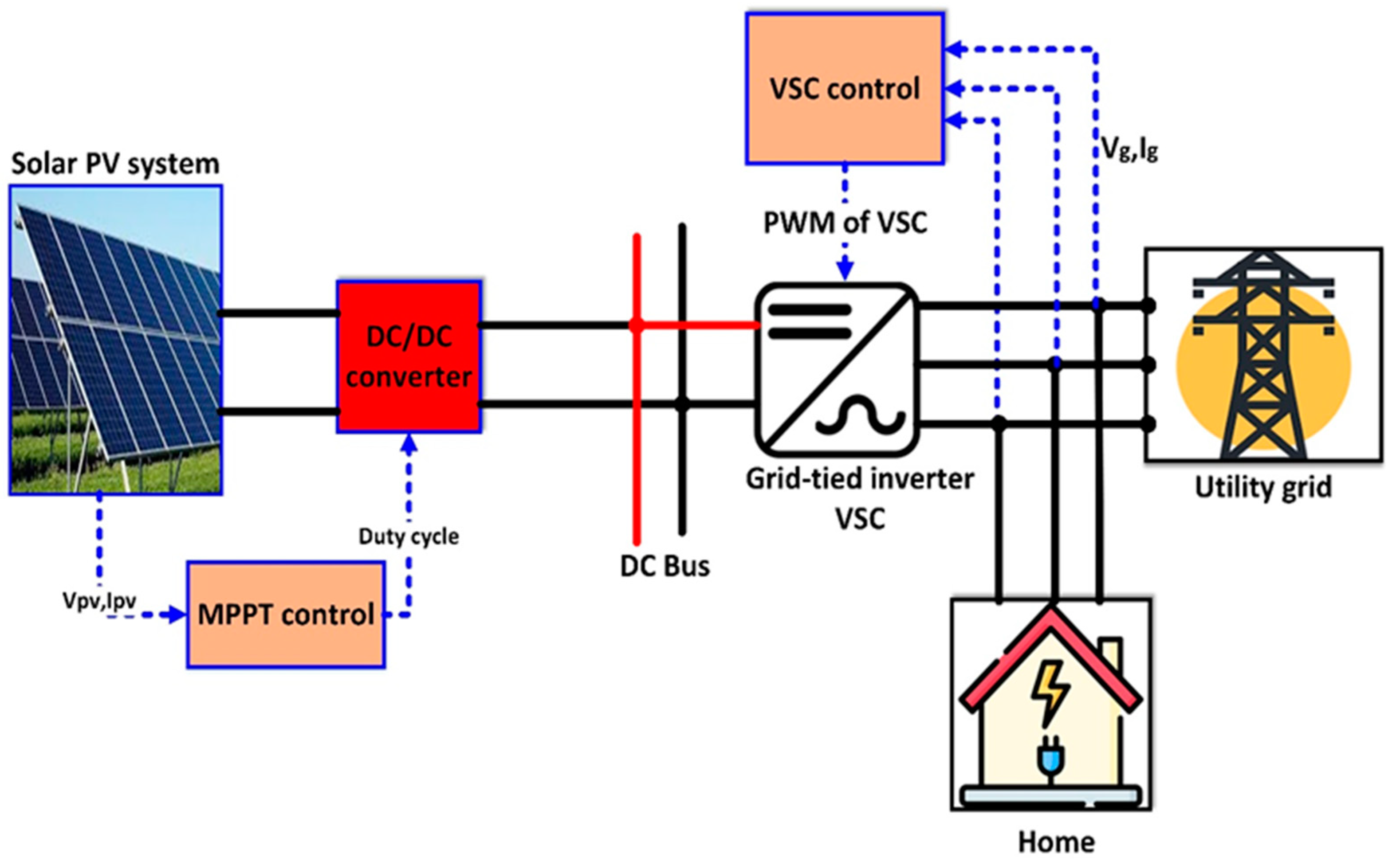
2. Grid-Tied Solar Inverter

2.1. Grid-Tied Inverter Operation

The inverter is an essential component of any solar power system, as it allows the electricity generated by the solar PV panels to be used on the grid. A system that is integrated with the utility grid utilizes a grid-tied inverter, which efficiently works on utility connected solar systems. The grid tied inverter charges the AC energy produced by the solar PV panels into the electricity grid. Verifiable energy from grid systems is utilized. The utility connection enables users to sell excess electricity back to the grid [25]. This helps in reducing reliance on traditional energy sources and saves on power expenses. A grid-tied inverter produces voltage and frequency that align with the electricity utility system. This helps the solar power system work at its peak power with MPPT technology in the solar inverters, which lets the solar PV panels produce the most energy possible. The connection stage consists of connecting the DC bus of the solar panels to the inverter, which will in turn supply the AC power to the house electrical panel and the grid. Additionally, a bi-directional meter is set up to track energy bought off the grid as well as power put on the grid. Grid-tied systems are also less expensive and more efficient because they do not need battery storage. Figure 1 shows a typical grid-tied solar inverter. The voltage source converter (VSC) is the most used in this application due to features such as simplicity and low-cost implementation. This converter consists of six switches, such as MOSFET or IGBTs, and they are triggered by PWM signals to ensure synchronization with grid via the VSC control block.

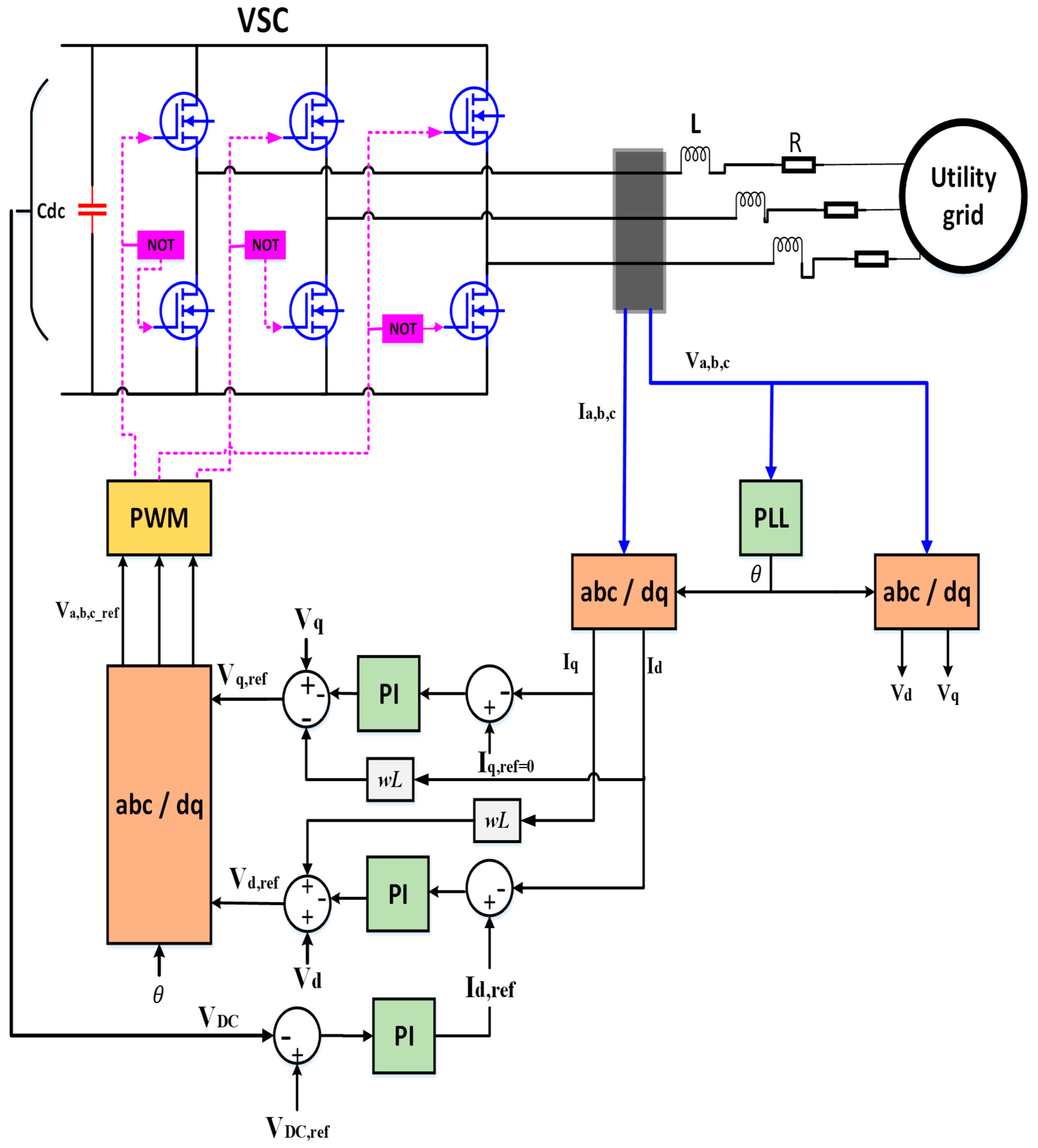
2.2. Modelling of Grid-Tied Inverter

In dq control, as shown in Figure 2, an inverter’s three-phase AC system is transformed to a two axes rotating on a frame. This assists in managing the active (d-axis) and reactive (q-axis) power better because it decouples them. A PLL coordinates the phase and frequency of the grid and the inverter and references them so that the inverter output is coordinated with grid voltage. The error is minimized by placing actuators that regulate the d and q component currents. These controllers ensure that the actual outcome matches the pre-defined outcome. In this case, PWM control is used to set the current to a desired power level and then send the pulse width modulation signals to the inverter. DC Link capacitors serve the purpose of low pass filters that smooth output by squelching high-frequency voltage noise. Synchronization of output powers and the grid voltage ensures the quality of the power delivered. The strategy discussed carefully controls the output power provided by the inverter, ensuring it is synchronized and ready to connect to the grid while maintaining the stability and desired energy dissolve. The dq control also works well with MPPT algorithms and fulfills grid code requirements, which is why its use is crucial for the stable and reliable operation of grid-tied solar inverters. Modeling of the inverter must be performed to implement this technique. For this reason, the αβ components of the voltage and current of the grid are obtained [26].
V α V β 0 = 1 1 2 1 2 0 3 2 3 2 1 2 1 2 1 2 V a V b V c
I α I β 0 = 1 1 2 1 2 0 3 2 3 2 1 2 1 2 1 2 I a I b I c
By applying the dq transformation, the following equations are obtained:
V d V q 0 = cos θ sin θ 0 sin θ cos θ 0 0 0 1 1 1 2 1 2 0 3 2 3 2 1 2 1 2 1 2 V a V b V c
where θ is the angle of the voltage grid:
I d I q 0 = cos θ sin θ 0 sin θ cos θ 0 0 0 1 1 1 2 1 2 0 3 2 3 2 1 2 1 2 1 2 I a I b I c
By solving Equations (3) and (4), the dq current and voltage are obtained [25,26]:
V d V q 0 = 2 3 cos θ 1 2 cos θ + 3 2 sin θ 1 2 cos θ 3 2 sin θ sin θ 1 2 sin θ + 3 2 cos θ 1 2 sin θ 3 2 cos θ 1 2 1 2 1 2 V a V b V c
I d I q 0 = 2 3 cos θ 1 2 cos θ + 3 2 sin θ 1 2 cos θ 3 2 sin θ sin θ 1 2 sin θ + 3 2 cos θ 1 2 sin θ 3 2 cos θ 1 2 1 2 1 2 I a I b I c
The parameters of the above equations can be defined as follows:
  • V α , V β are the voltages of the αβ component.
  • V a , V b , and V c are the grid voltages of phase a, b, and c.
  • I α , I β are the currents of the αβ component.
  • I a , I b , and I c are the grid currents of phase a, b, and c.
  • V d ,   V q are the grid voltages of the dq component.
  • I d ,   I q are the grid currents of the dq component.
However, the grid voltage and currents are measured and transformed to dq-axis components via Park’s transformation. The control of I d , r e f of the grid is performed via measurement of the DC voltage of the DC bus from the PV system, which is fed to the inverter. The PI controller is used to adjust the reference current of the direct axis current. The I q , r e f equals zero, which makes the reactive power zero. The phase-locked loop (PLL) block is used to produce the angle of the grid’s voltage or frequency to ensure that the inverter output remains synchronized with the utility grid. The PI controller regulates the dq axis currents. The I d and I q currents are controlled to generate the reference values of the dq-axis voltages as follows:
V d , r e f = V d + I q . w L u d ( t )
V q , r e f = V q I d . w L u q ( t )
where w is the angular frequency, L is the inductance of the grid, and u d t and u q ( t ) are the control signal of the PI controller for the I d and I q components. The currents along the dq axis are compared to the real currents, and the difference is compensated by the PI controller so that the power and grid control requirements are satisfied as follows:
u d t = k p I d , r e f I d + k i 0 t I d , r e f I d d t
u q t = k p I q , r e f I q + k i 0 t I q , r e f I q d t
where k p is the proportional gain, and k i is the integral gain. In this work, the parameters of this control are calculated via the trial-and-error method.

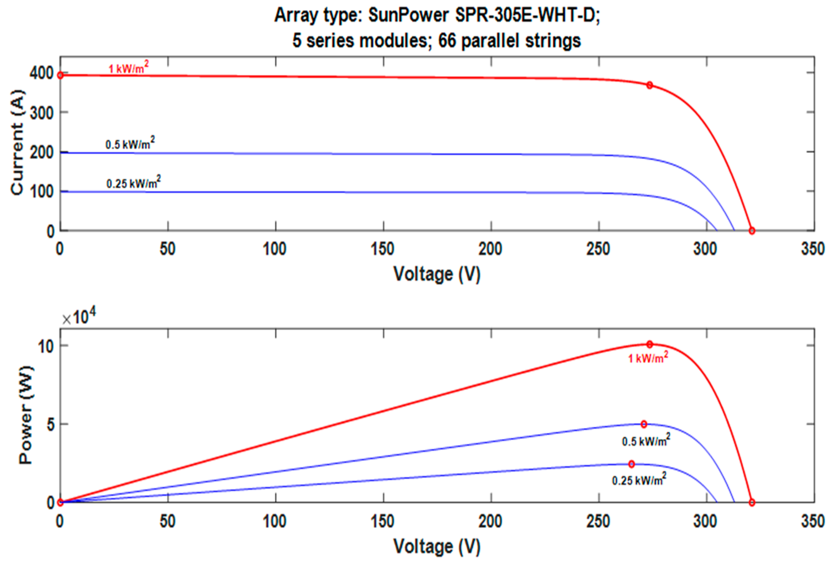
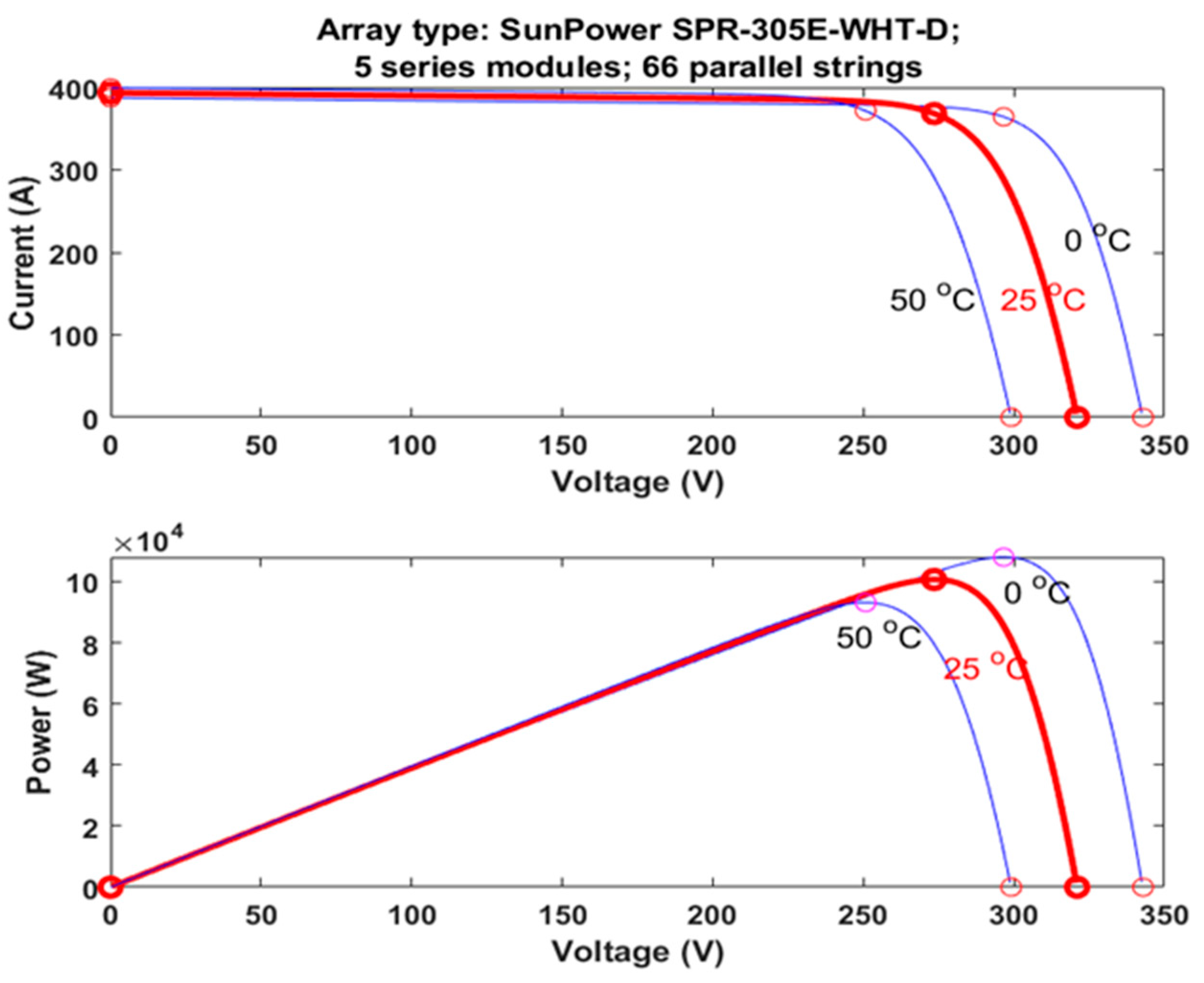
3. Proposed PV System

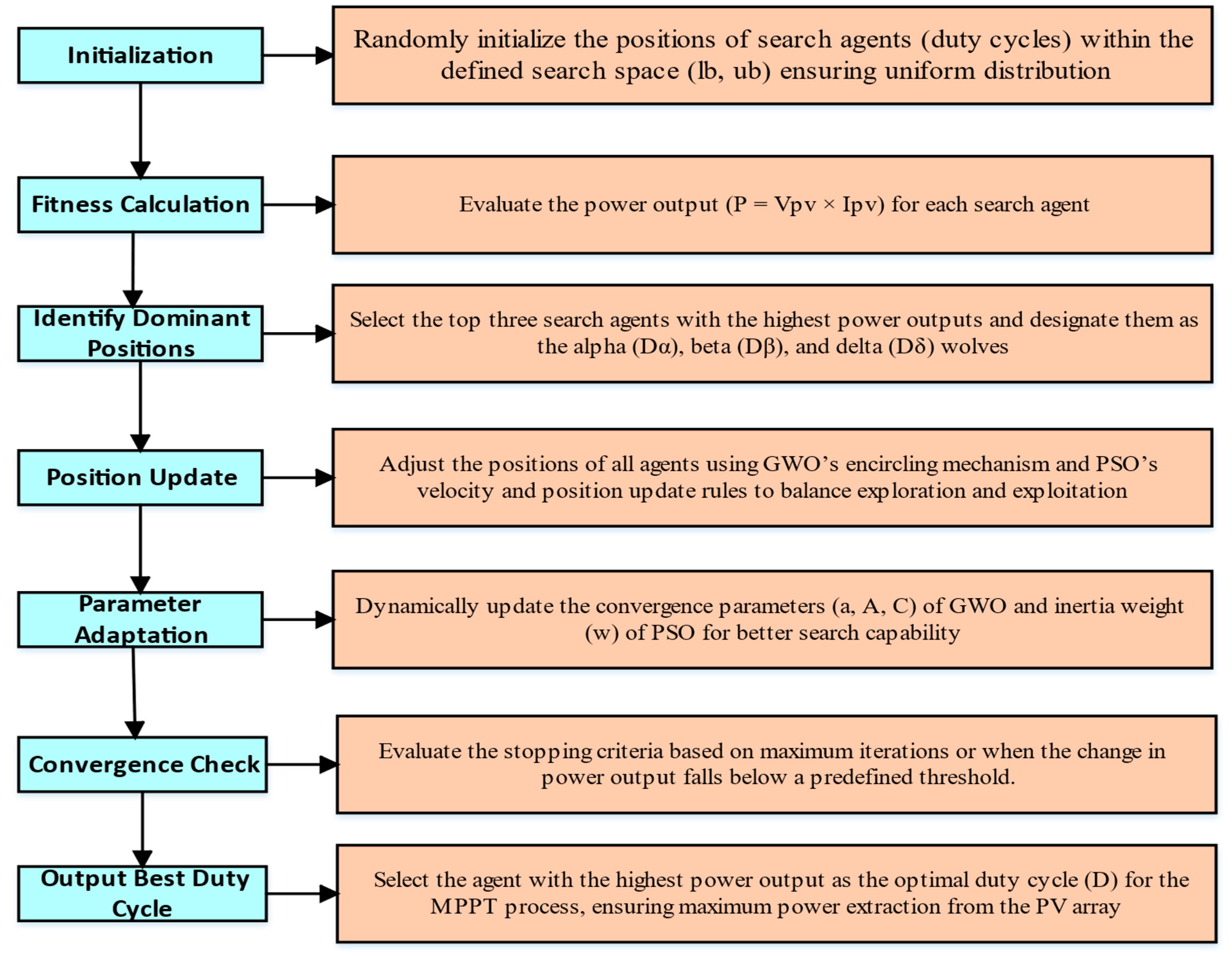
3.1. Proposed MPPT Method

Modeling the solar array in MATLAB is performed in order to analyze and optimize the performance of a PV system under different weather conditions. Using the PV array tool in the MATLAB, the proposed PV system consists of dive series modules with 66 parallel strings. In this work, the benchmark 100 kW Grid-tied PV system is used. The P-V and I-V curves of the system under different irradiance and varying temperature are shown in Figure 3 and Figure 4. The PV panels used in this configuration have the technical parameters as specified in Table 1.

3.2. Proposed Hybrid MPPT Method

3.2.1. PSO Algorithm

PSO is a metaheuristic algorithm inspired by nature, first designed by Kennedy et al. in 1995 [27]. It was inspired mainly by the foraging behavior of flocks of birds. Swarm intelligence-based, the PSO algorithm operates a swarm of cooperative particles that search the global search space. Every particle holds a special position, x i , and velocity, v i , which may be a potential candidate solution. In the search process, a particle’s location is controlled by a neighborhood’s best location, Pbest, i, and the global optimum location among all the particles in the entire population, G best . Thus, the particle location, x i , will be updated according to the following equation:
x i k + 1 = x i k + v i k + 1
where vi is the particle velocity, which is computed by the following equation:
v i k + 1 = w v i k + c 1 r 1 ( P best , i x i k ) + c 2 r 2 ( G best x i k )
where k indicates the iteration numbers, c 1 and c 2 are the acceleration coefficients, r 1 and r 2 are uniformly distributed random numbers in the interval [0, 1], and w is the inertia weight.

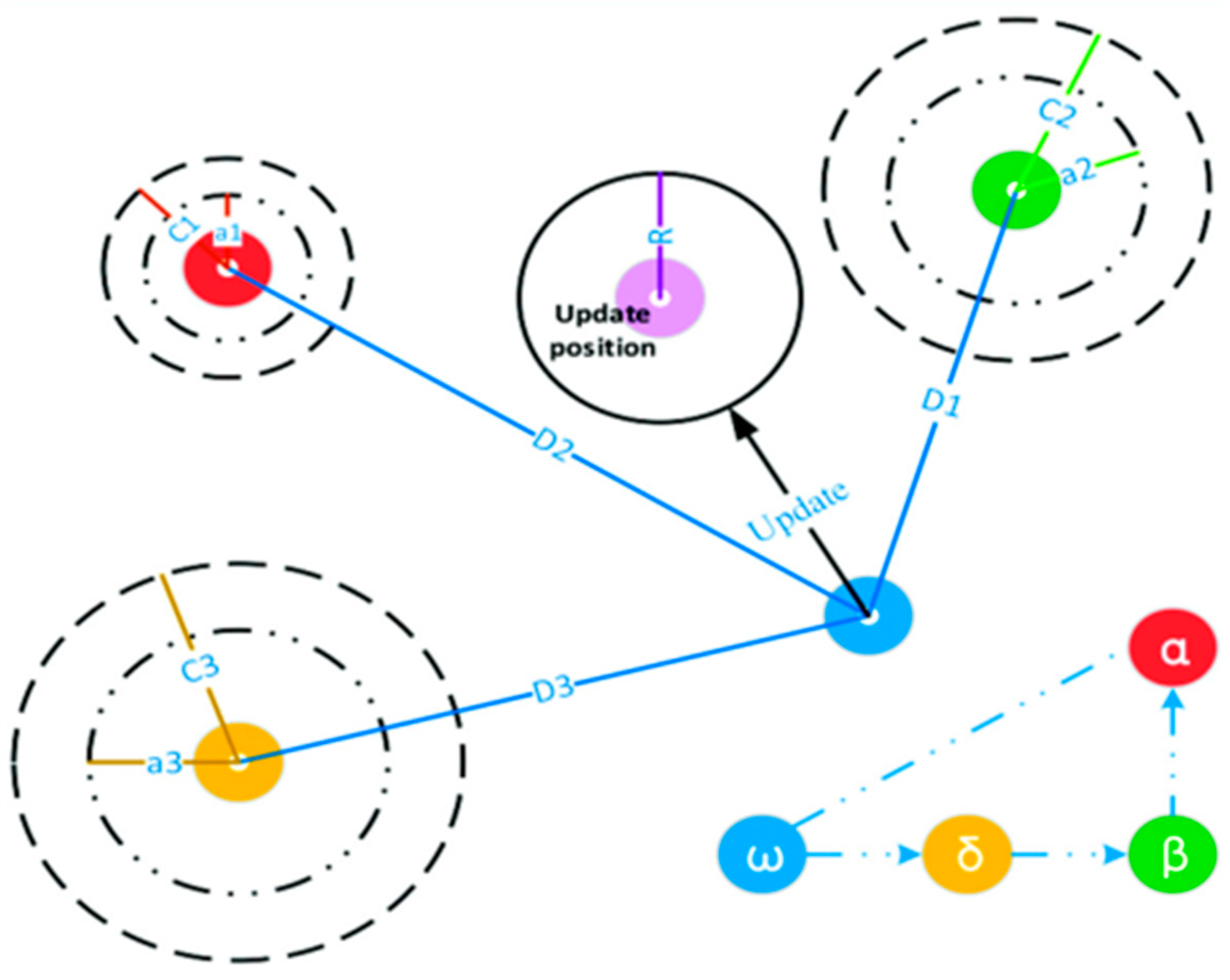
3.2.2. GWO Algorithm

GWO is a new member of the SI-based metaheuristic algorithms first introduced by Mirjalili et al. in 2014 [28]. This algorithm imitates the social behavior of grey wolves and their leadership hierarchy and hunting behavior in the natural environment. Grey wolves in a pack have an excessively strict dominant social hierarchy, with four levels. The leaders who are male and female are referred to as alpha (α). The helper wolves who support the leaders are referred to as beta (β) and are the second level in the hierarchy of grey wolves. The third level of the hierarchy is denoted as delta (δ), while the rest of the wolves are denoted as omega (ω) and are the lowest level in the hierarchy. The grey wolves’ dominance in this ladder decreases from alpha (α) to omega (ω). The GWO algorithm partitions the candidate solutions into four sub-groups to represent the leadership hierarchy: alpha is the best one, beta is the second-best one, delta is the third-best one, and omega represents the rest. This algorithm’s process of solution generation has three stages. The first is encircling prey. This process is the first stage of hunting, in which the grey wolves begin to encircle the prey. This stage is mathematically modelled as follows:
A = 2 a r 1 a
C = 2 r 2
where elements of a are linearly diminished from 2 to 0 iterations, and r₁, r₂ are vectors in [0, 1].
Hunting. This process is guided by alpha (α) (the best candidate solution), beta (β), and delta (δ), since they are more likely to know the probable position of the optimal solution (i.e., the prey). The rest of the search agents, including omegas, update their locations based on the best search agent location. Thus, a search agent location is updated by applying the following equations:
D α = C 1 X α X
D β = C 2 X β X
D δ = C 3 X δ X
X 1 = X α A 1 D α
X 2 = X β A 2 . D β
X 3 = X δ A 3 . D δ
X ( t + 1 ) = X 1 + X 2 + X 3 3
Prey searching and attacking prey. These processes are guaranteed by adaptive values a and A varying, which enables the GWO algorithm to switch between exploration and exploitation in a smooth way. In the process of the reduction of A, and when |A| ≥ 1, half of the iterations are meant to explore (i.e., stray away from prey), and the other half of the iterations are spent on exploitation if |A| < 1 (i.e., the search moves towards the prey). Based on alpha, beta, and delta locations, the process employed by a search agent (also referred to as a search grey wolf) to update its location in the 2D search space is as depicted in Figure 5 [29]. From the figure, it is apparent that the best solution would be in a random location inside a circle in the search space based on alpha, beta, and delta locations. Otherwise, alpha, beta, and delta estimate prey location (optimal solution), and other wolves update their location randomly in the neighborhood of prey [28].

3.2.3. Proposed GWO-PSO Algorithm

The hybrid GWO–PSO is a SI-based search algorithm developed in 2017 by Narinder Singh et al. [30]. The fundamental hybridization concept of the algorithm is to combine the exploratory power in the GWO algorithm on one side and the exploitation power in the PSO algorithm on the other side to achieve the power of both variants. To this end, the best three search agents’ locations (α, β, and δ) are updated in the search space by the new equations mentioned in (22) instead of the standard equations of (15). That is, the exploration and exploitation of grey wolves in the search space are regulated by an inertia constant (w) modelled by the following equations:
D α = C 1 X α w · X
D β = C 2 X β w · X
D δ = C 3 X δ w · X
X 1 = X α A 1 D α
X 2 = X β A 2 D β
X 3 = X δ A 3 D δ
On the basis of all the above, the combination of GWO and PSO variants is performed by updating the velocity and position equations as follows:
v i k + 1 = w . v i k + c 1 r 1 X 1 x i k + c 2 r 2 X 2 x i k + c 3 r 3 X 3 x i k
x i k + 1 = x i k + v i k + 1
Implementation of the hybrid GWO–PSO for MPPT. For the realization of MPPT, a DC–DC power converter is employed to regulate the PV array output to the load, and the position of all the search agents in the hybrid GWO–PSO algorithm is defined as the decision variable, which in this case is the duty cycle value ( d c ) of the power converter. Accordingly, Equations (22)–(27) are adjusted to the following:
D α =   C 1 d c α w d c
D β =   C 2 d c β w d c
D δ =   C 3 d c δ w d c
d c 1 = d c α A 1 D α
d c 2 = d c β A 2 D β
d c 3 = d c δ A 3 D δ
v i k + 1 = w · ( v i k + c 1 r 1 ( d c 1 d c i k ) + c 2 r 2 ( d c 2 d c i k ) + c 3 r 3 ( d c 3 d c i k ) )
d c i k + 1 = d c i k + v i k + 1
The search agents receive fitness evaluation based on duty cycle values at this stage, which represents the power converter output power ( Ppv ) of the PV array. The duty cycles require evaluation through the successful generation of pulse-width-modulation (PWM) signals. The digital controller generates PWM signals in a successive manner based on the duty cycle ( d c i ) values. Then, the corresponding PV power is established. The calculation of ( Vpv i ) requires a combination of measured MPPT voltage ( Vpv i ) and measured MPPT current ( Ipv i ) . The correct sampling process for assessments requires a suitable time duration between both measurement points. A power converter needs settling time to complete its operation such that the duty cycle (Ts) duration must surpass it. The following inequality is implemented to detect climate condition changes:
Ppv new Ppv last Ppv last Δ Ppv ( % )
Figure 6 displays the procedure of implementation of the GWO-PSO algorithm. The parameters of the used algorithms are listed in Table 1.

4. Results and Discussion

The proposed system implemented in MATLAB/Simulink is shown in Figure 7. The system consists of a 100 kW PV system with a boost converter, GOW-PSO MPPT controller, VSC, and grid. The results of the simulations discussed in this section have been acquired with step changes in irradiance whilst keeping the temperature constant, as detailed in the next sub-sections.

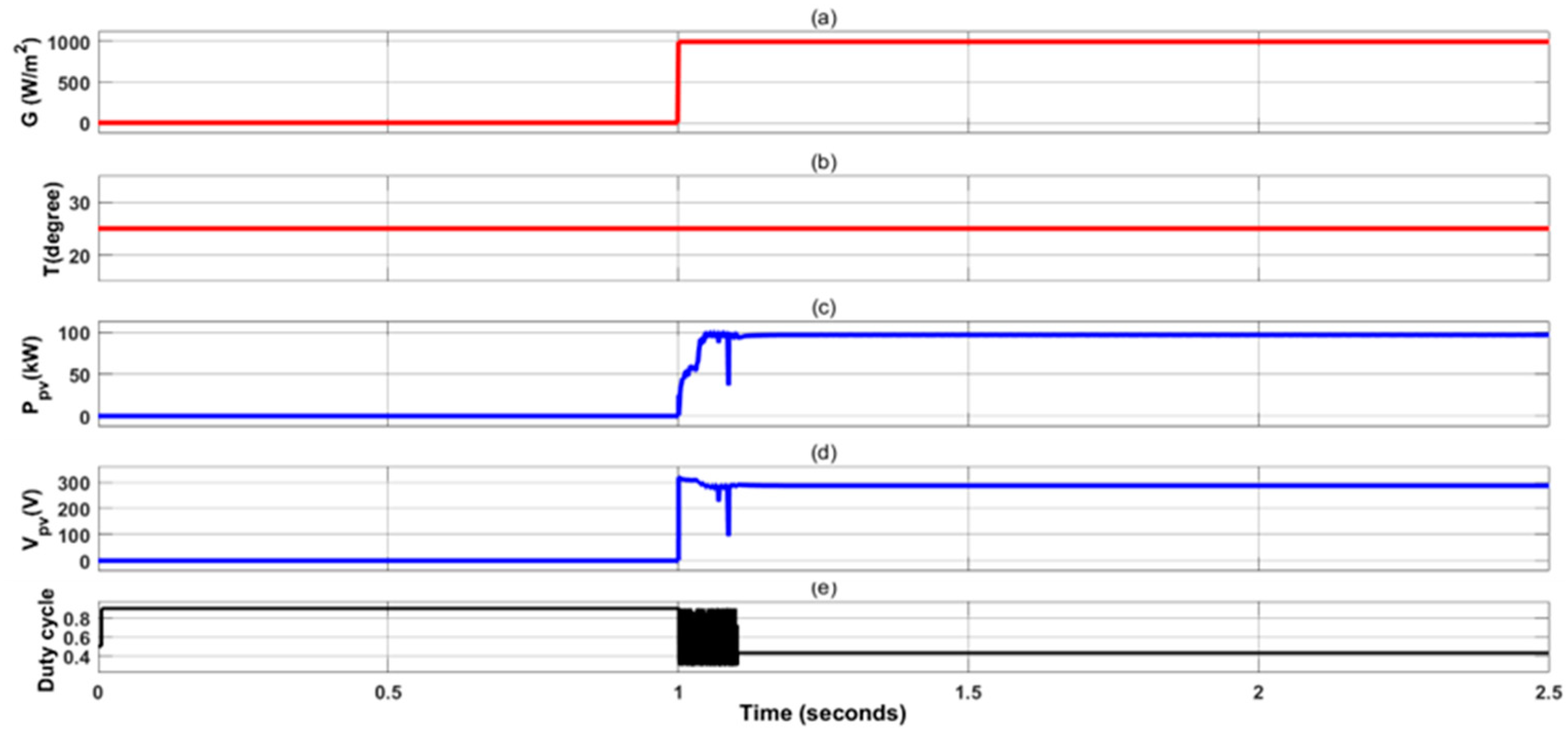
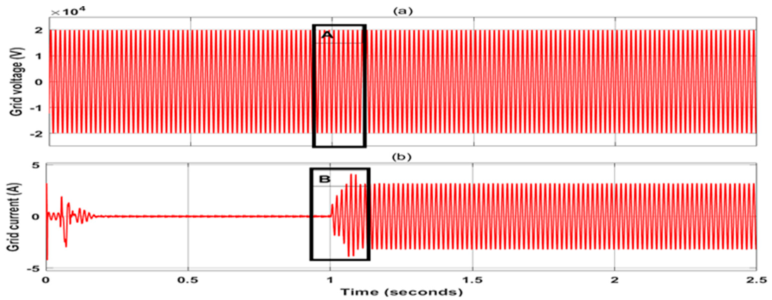
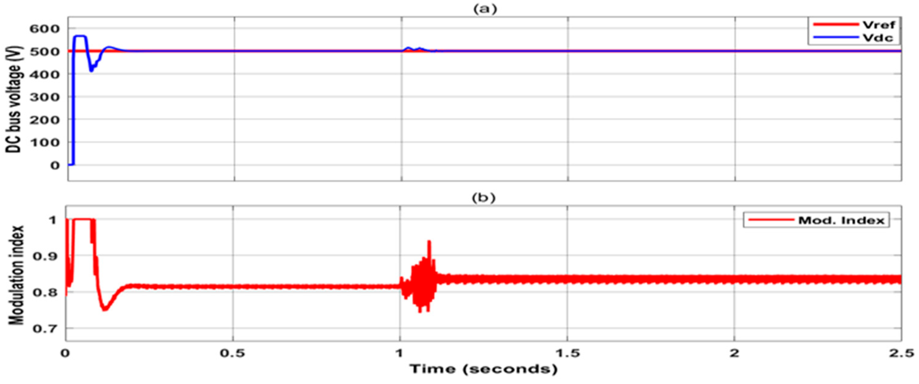
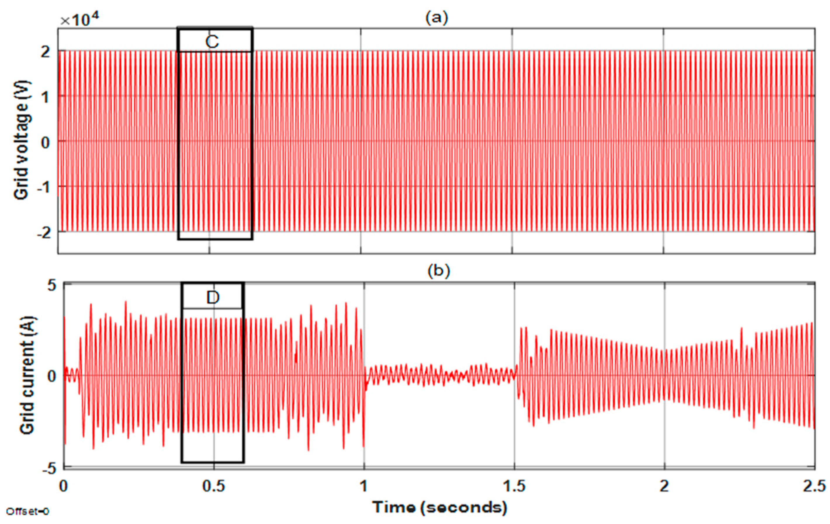
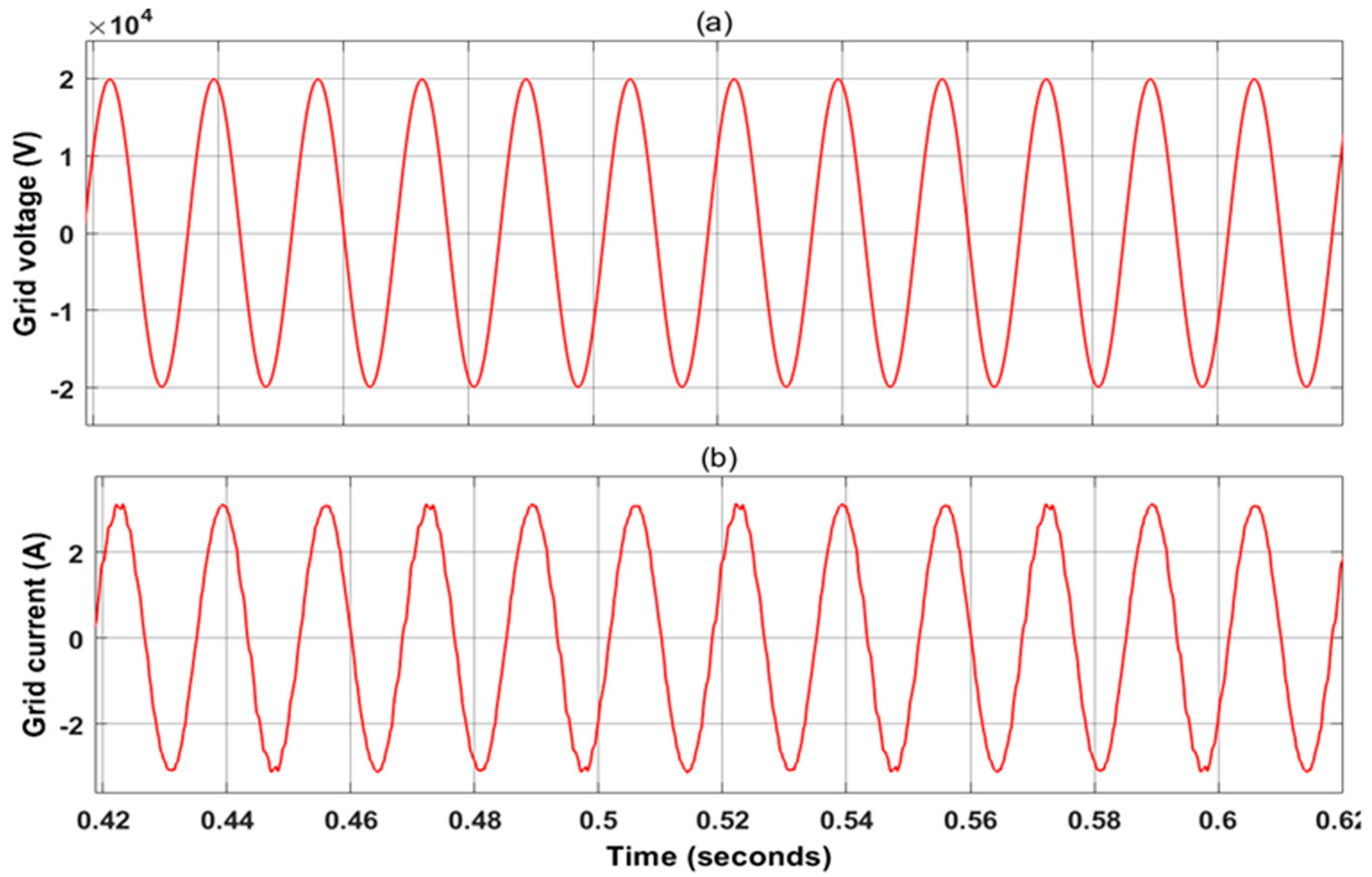
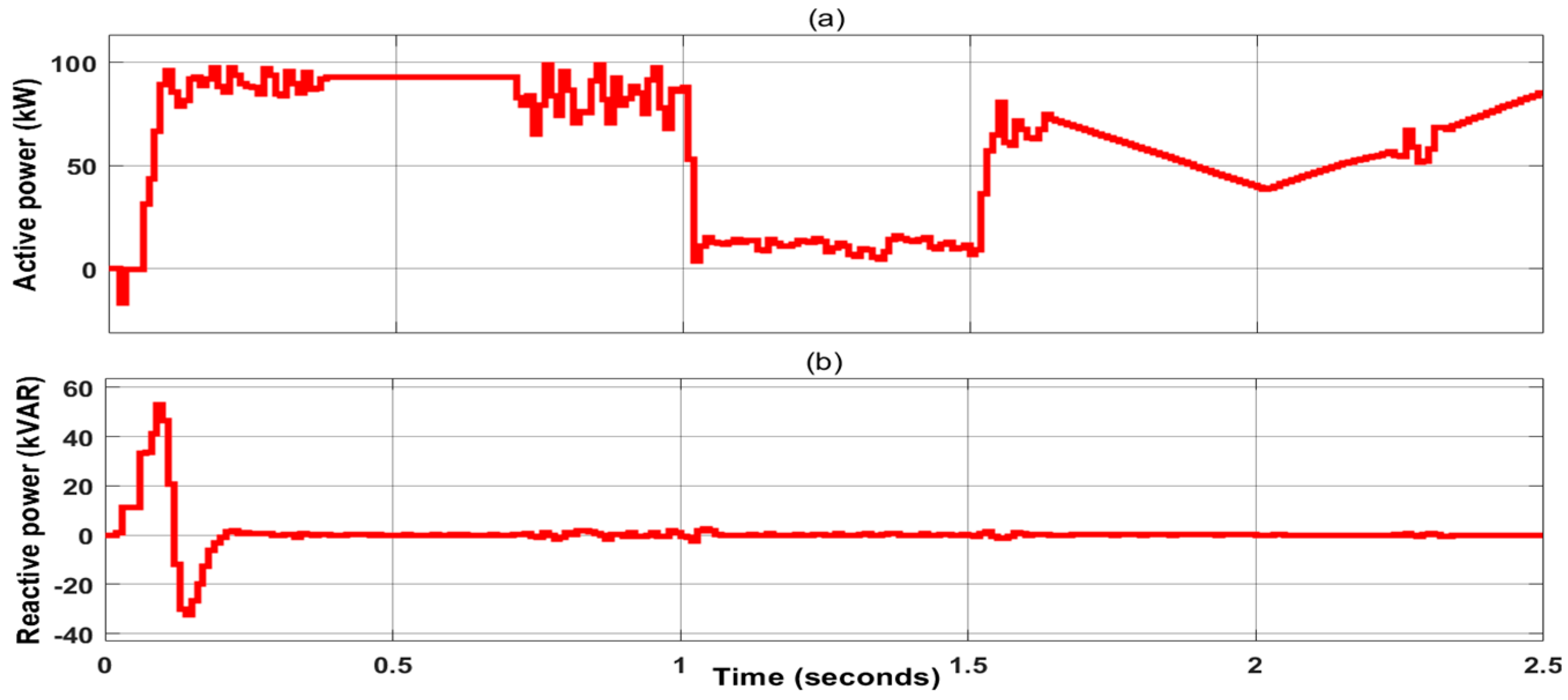
4.1. Case 1: Step Change in Irradiance

Figure 8 shows how the PV system reacts to variations in irradiance while maintaining a constant temperature of 25 °C. For instance, the power of the PV system rapidly changed during the first second due to an increase in irradiance from 0 to 1000 W/m2, but within the next second, the PV power output began to rise. Though the PV voltage initially responded with fluctuations, it rapidly returned to stable mode. The duty cycle was actively varied throughout the change in irradiance, which shows the effectiveness.
Figure 9 presents the grid voltage and current based on the used irradiance profile. As observed, the grid voltage is stable with 25 KV during the simulation, with a pure sine wave. The current injected to the grid is increased by increasing the solar power or irradiation. The rms value of this current is about 3 A. The obtained current is very pure and has a low total harmonic distortion, less than 1%. The zoomed in presentation of these results is clarified in Figure 10. The goal of this figure is to clear the graphs of the results and show the accuracy of the used controller and MPPT method.
Figure 11, presents the DC bus voltage and the modulation index for a grid-tied PV inverter system. As observed, the DC bus voltage tracks the reference voltage closely and has an initial transient, and the Vdc stabilizes at about 500 V. This shows good DC link voltage regulation due to the robust PI controller. In addition, there is the modulation index, which changes as needed to provide steady power. The modulation index tends to be high, but after some transient disturbances, it drops to steady values. There is some ripple observed around 1 s, which is probably due to some changes in the irradiance or the load. The system is near steady-state operation after having some minor disturbances.
Figure 12 provides the curves of the active power and reactive power outputs for a grid PV inverter system under various conditions. As seen, the active power oscillates between −20 kW and 20 kW during startup due to system transients. Following this, an increase in power is observed. After the transitory phase, the active power levels off around 20 kW until the 1 s mark, at which time 100 kW is reached, indicating that the PV controller can track the maximum power point as irradiance is raised. Figure 12b shows a graph of a reactive power response. The first part (0 s–1 s) shows the flexing reactivity power response increasing from values of −20 kVAR to about 40 kVAR, caused by transient conditions. Next, the new steady state is reached, and reactive power tends to settle around the region of 0 kVAR. This point ensures that the inverter operates like a grid-friendly device with a high-power factor. After about the first second, the power seems to be relatively stable, with only minor ripples noted.

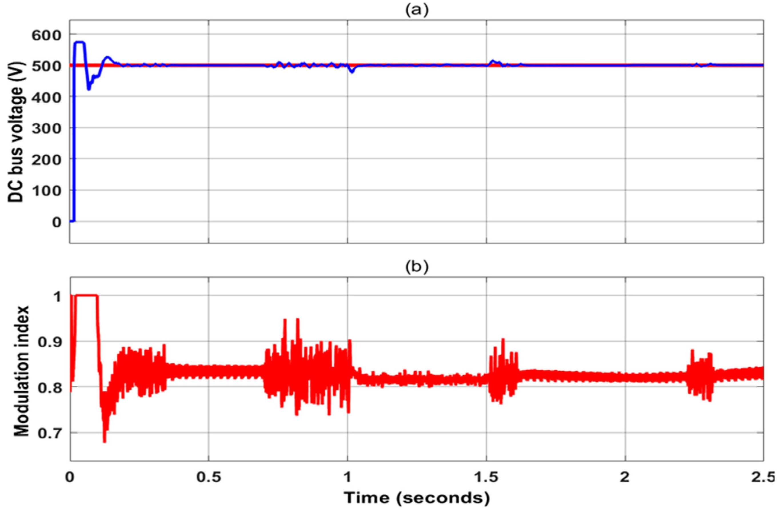
4.2. Case 2: Variable Varying in Irradiance

In order to test the performance of the used GWO-PSO, the weather conditions of irradiance and temperature are changed in variable values, as shown in Figure 13. As observed, the achieved power of the PV system from time 0 s to 0.7 s has a stable output. After this time, when the temperature is decreased, the MPPT algorithm varies the duty cycle to adjust the MPP, and lower power is achieved when the irradiance is reduced from 1000 W/m2 to 200 W. The PV power is 16 kW. The voltage of the PV system is varied when the temperature varies, and this value is approximately constant, at 300 V.
Furthermore, the used irradiance profile facilitates the extraction of grid voltage and current, as seen in Figure 14. The current fed into the grid escalates with the augmentation of solar power or irradiation. This current is very low when the irradiance drops from 1000 W/m2 to 200 W/m2. The injected current has low total harmonic distortion (THD < 1%), and it is in phase with the grid voltage. This means that the power factor is close to unity, which is a sign of good control and has little to do with the MPPT algorithm choice. This is clearly shown in Figure 15. This figure shows the zoom results of the C and D areas of the curves. The current value of phase-a is 2.5 A (RMS).
Figure 16 displays the DC voltage curve obtained under the suggested MPPT with respect to the modulation index. As observed, the DC bus voltage has a fast response, with minimum overshoot or undershoot. When the irradiation varies, the control method based on the proposed GWO-PSO maintains the DC voltage with its reference (500 V). Furthermore, the modulation index adjusts as required to maintain consistent power output. The modulation index is initially elevated, but after brief perturbations, it stabilizes at consistent levels. Figure 17 illustrates the active power and reactive power of the grid. As presented, the active power was varied based on the weather conditions, and the reactive power is zero. This means the inverter can provide real power with a high power factor.

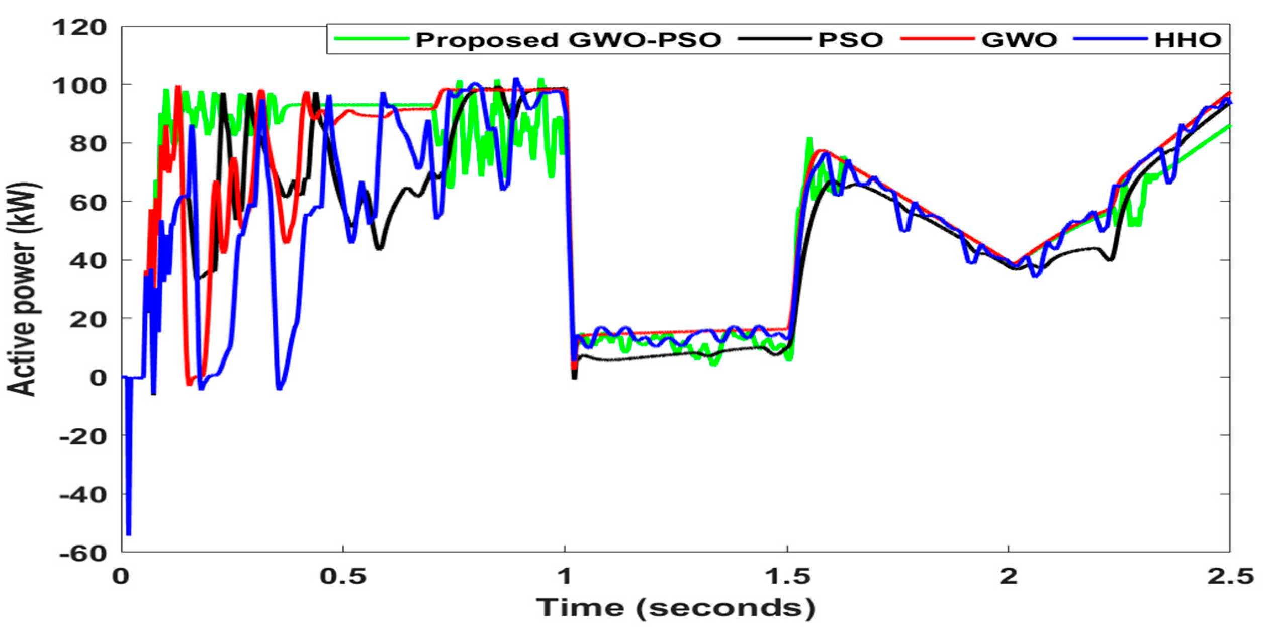
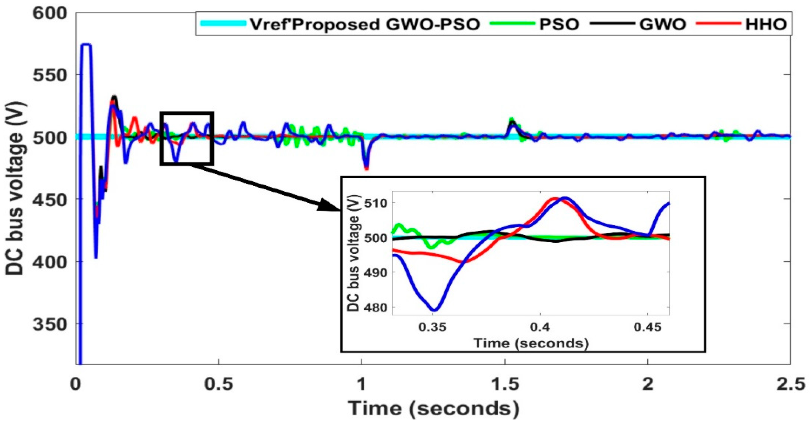
4.3. Case 3: Comparison with Existing Methods

The overall performance of the PV system is greatly affected by irradiation changes. To test the proposed MPPT algorithm, a comparison with existing methods is presented in this section. These algorithms seek to extract as much power and inject it into the grid according to the solar insolation and temperature values. The proposed method outperforms all others in the lowest peak overshoot (see Figure 18). This leads to lower loss of derived power, improved system stability, and a faster response to changing environmental conditions. As compared to the PSO, GWO, and HHO techniques, this approach is much better. Unfortunately, these traditional algorithms are much slower to respond to disturbances, which greatly increases the time spent in overshoot conditions, leading to lower system efficiency. Performing these comparisons not only proves the effectiveness of the proposed algorithm, it also explains how different MPPT techniques work within the same environment. This is very important for decision-making and design purposes, especially when planning for the practical implementation of MPPT controllers in PV systems. Figure 19 shows the comparison of DC bus voltage between the proposed, PSO, GWO, and HHO algorithms.
The numerical metrics of the comparison are presented in Table 2. As measured by the criteria, the proposed GWO-PSO approach is the most accurate. It also achieves the top spot for lowering rise and settling times as well as overshoot of the DC bus voltage. The PSO performs metamorphically, but it exhibits more evidential overshoot than the hybrid method. Because GWO and HHO respond more slowly and have much higher overshoot values, they cannot keep up with the others when it comes to quickly stabilizing the DC bus voltage. The table shows a comparison of several MPPT methods’ dynamic performance in controlling the DC bus voltage of a photovoltaic system. We evaluated the performance using rise time, settling time, overshoot, and other measures.
The GWO-PSO hybrid method has the best performance in the rapid response category, with the rise time being approximately 0.17 s and the settling time being about 0.71 s. It has the lowest overshoot, at 2.7%, indicating that stabilization involves little deviation from 500 V.
  • PSO has slightly higher settling and rise times of 0.106 s and 0.24 s, respectively. In overshoot, however, it exceeds the mark, showing a value of 4.3%. It shows efficiency but a lack of stability compared to GWO-PSO.
  • GWO achieves moderate performance. We recorded the rise time and settling time at 0.36 s and 0.145 s, respectively. A 7% overshoot suggests a higher fluctuation range of a given output signal before a steady state is achieved.
  • HHO has the slowest response with the greatest rise time (0.40 s) and has the longest settling time (0.178 s). Further, its overshoot of 9% indicates significant fluctuations, which makes this method the least stable technique.
The active power injected to the grid is analyzed in this section. The achieved results are inserted to show the performance and response for each MPPT method under varying irradiance levels. The analysis of these results includes the proposed GWO-PSO, which suggest the method is successful, achieving low overshoot in the active power value, with 4%. This method is the faster method when compared with other techniques, where its settling time and rise time are 0.260 s and 0.118 s, respectively. The PSO algorithm response is better than the others in terms of overshoot, with 7%, and the rise time is 0.203 s. The GWO and HHO presented low response and poor power quality, having slow response to the changes of the irradiance. GWO has a 0.245 s rise time and 0.65 s settling time, while the HHO ‘s rise time is 0.280 s and its settling time is 0.8 s. Also, the overshoot in the power is very high, which may cause damage to the inverter. As observed, during transition conditions, especially around 1 s, when a significant power drop is experienced due to some changes in irradiance or load, GWO-PSO is quick to respond, while HHO becomes quite volatile in its overshoot, which is a troubling sign of adaptivity. In the final stage (after two seconds), all algorithms try to settle around a power level, but GWO-PSO is still better, as it tends to track more smoothly and adapt quickly. All in all, the hybrid GWO-PSO algorithm is superior in performance when compared to independent implementations of PSO, GWO, and HHO because it has a better response to change, less oscillation, and faster convergence, making it more robust for MPPT applications in grid-tied PV inverters.

5. Conclusions

The presented work aims to develop and validate of a new hybrid Maximum Power Point Tracking (MPPT) technique based on using GWO and PSO algorithms for grid-tied solar inverters. The capacity of the solar system used in this work is 100 kW. The PV system is linked to the DC bus via a boost converter. The voltage source converter is controlled and synchronized with the grid using dq control theory. The simulation results are obtained using the MATLAB simulation program. The weather conditions, such as irradiance and temperature, are varied, with different two cases, in order to verify the suggested MPPT method.
The hybrid technique is better than the classical methods of GWO, PSO, and HHO in terms of both tracking speed, overshoot, and steady-state oscillations of system performance in changing environments. The examination of these data includes the suggested GWO-PSO approach, which successfully achieves a low overshoot of 4% in transferring power to the grid. Finally, this approach is the more expedient option when compared to other methods, with a settling time of 0.26 s and a rising time of 0.118 s. For future work, the use of advanced control strategies, including model predictive or artificial intelligent controllers for multi-level inverters, may prove useful in optimizing power conversion efficiency and minimizing switching loses.

Author Contributions

Conceptualization, S.A.T., Z.S.A.-S. and M.A.A.; Methodology, S.A.T., Z.S.A.-S. and M.A.A.; Software, S.A.T., Z.S.A.-S. and M.A.A.; Validation, S.A.T., Z.S.A.-S. and M.A.A.; Formal analysis, S.A.T., Z.S.A.-S. and M.A.A.; Investigation, Z.S.A.-S. and M.A.A.; Resources, M.A.A. and M.A.I.; Data curation, M.A.A., M.A. and M.A.I.; Writing—original draft, M.A. and M.A.I.; Writing—review & editing, M.A. and M.A.I.; Project administration, M.A.; Funding acquisition, M.A. All authors have read and agreed to the published version of the manuscript.

Funding

This research was funded by the Deanship of Scientific Research at Northern Border University, Arar, KSA, for funding this research (through the project number NBU-FFR-2025-2124-01).

Data Availability Statement

Data are contained within the article.

Acknowledgments

The authors extend their appreciation to the Deanship of Scientific Research at Northern Border University, Arar, KSA, for funding this research (through the project number NBU-FFR-2025-2124-01).

Conflicts of Interest

The authors declare no conflicts of interest.

Abbreviations

The following abbreviations are used in this manuscript:
DOAJDirectory of open access journals
LDLinear dichroism

References

  1. Shafiullah, M.; Ahmed, S.D.; Al-Sulaiman, F.A. Grid Integration Challenges and Solution Strategies for Solar PV Systems: A Review. IEEE Access 2022, 10, 52233–52257. [Google Scholar] [CrossRef]
  2. Bialasiewicz, J.T. Renewable Energy Systems with Photovoltaic Power Generators: Operation and Modeling. IEEE Trans. Ind. Electron. 2008, 55, 2752–2758. [Google Scholar] [CrossRef]
  3. Abbas, F.A.; A.Obed, A.; Alhasiri, A.; Yaqoob, S.J. A Hybrid Renewable Sources Implementation for a DC Microgrid with Flatness-Nonlinear Control to Achieve Efficient Energy Management Strategy. J. Tech. 2023, 5, 16–27. [Google Scholar] [CrossRef]
  4. Khalaf, H.H.; Al-Sagar, Z.S.; Mohammad, A.T.; Fadhil, H.A. Optimization of Neurons Number in Artificial Neural Network Model for Predicting the Power Production of PV Module. J. Tech. 2024, 6, 69–77. [Google Scholar] [CrossRef]
  5. Kadhim, N.A.; Obed, A.A.; Abid, A.J.; Saleh, A.L.; Hassoon, R.J. A Systematic Review for Reconfiguring Photovoltaic Arrays under Conditions of Partial Shading. Electr. Eng. Tech. J. 2024, 1, 20–34. [Google Scholar] [CrossRef]
  6. Shaker, F.N.; Obed, A.A.; Abid, A.J.; Saleh, A.L.; Hassoon, R.J. Energy Management Strategy for PV PSO MPPT / Fuel Cell/Battery Hybrid System with Hydrogen Production and Storage. J. Tech. 2023, 5, 52–60. [Google Scholar] [CrossRef]
  7. Yaqoob, S.; Hussein, A.; Saleh, A.L. Low Cost and Simple P&O-MPP Tracker Using Flyback Converter. Solid State Technol. 2020, 63, 9676–9689. [Google Scholar]
  8. Yaqoob, S.J.; Obed, A.A. Modeling, Simulation and Implementation of PV System by Proteus Based on Two-Diode Model. J. Tech. 2019, 1, 39–51. [Google Scholar] [CrossRef]
  9. Shi, J.; Zhang, W.; Zhang, Y.; Xue, F.; Yang, T. MPPT for PV Systems Based on a Dormant PSO Algorithm. Electr. Power Syst. Res. 2015, 123, 100–107. [Google Scholar] [CrossRef]
  10. González-Castaño, C.; Restrepo, C.; Kouro, S.; Rodriguez, J. MPPT Algorithm Based on Artificial Bee Colony for PV System. IEEE Access 2021, 9, 43121–43133. [Google Scholar] [CrossRef]
  11. Tian, A.-Q.; Chu, S.-C.; Pan, J.-S.; Liang, Y. A Novel Pigeon-Inspired Optimization Based MPPT Technique for PV Systems. Processes 2020, 8, 356. [Google Scholar] [CrossRef]
  12. Eltamaly, A.M. A Novel Musical Chairs Algorithm Applied for MPPT of PV Systems. Renew. Sustain. Energy Rev. 2021, 146, 111135. [Google Scholar] [CrossRef]
  13. Pradhan, C.; Senapati, M.K.; Ntiakoh, N.K.; Calay, R.K. Roach Infestation Optimization MPPT Algorithm for Solar Photovoltaic System. Electronics 2022, 11, 927. [Google Scholar] [CrossRef]
  14. Kumar, D.; Chauhan, Y.K.; Pandey, A.S.; Srivastava, A.K.; Kumar, V.; Alsaif, F.; Elavarasan, R.M.; Islam, M.R.; Kannadasan, R.; Alsharif, M.H. A Novel Hybrid MPPT Approach for Solar PV Systems Using Particle-Swarm-Optimization-Trained Machine Learning and Flying Squirrel Search Optimization. Sustainability 2023, 15, 5575. [Google Scholar] [CrossRef]
  15. Chao, K.-H.; Rizal, M.N. A Hybrid MPPT Controller Based on the Genetic Algorithm and Ant Colony Optimization for Photovoltaic Systems under Partially Shaded Conditions. Energies 2021, 14, 2902. [Google Scholar] [CrossRef]
  16. Ahmed, H.S.; Abid, A.J.; Obed, A.A.; Saleh, A.L.; Hassoon, R.J. Maximizing Energy Output of Photovoltaic Systems: Hybrid PSO-GWO-CS Optimization Approach. J. Tech. 2023, 5, 174–184. [Google Scholar] [CrossRef]
  17. Refaat, A.; Ali, Q.A.; Elsakka, M.M.; Elhenawy, Y.; Majozi, T.; Korovkin, N.V.; Elfar, M.H. Extraction of Maximum Power from PV System Based on Horse Herd Optimization MPPT Technique under Various Weather Conditions. Renew. Energy 2024, 220, 119718. [Google Scholar] [CrossRef]
  18. Xu, S.-Z.; Zhong, Y.-M. NSNPSO-INC: A Simplified Particle Swarm Optimization Algorithm for Photovoltaic MPPT Combining Natural Selection and Conductivity Incremental Approach. IEEE Access 2024, 12, 137760–137774. [Google Scholar] [CrossRef]
  19. Lei, G.; Yan, C.; Cai, L.; He, C.; Dai, N.; Li, S.; Liu, J. IGWO-VINC Algorithm Applied to MPPT Strategy for PV System. Int. J. Photoenergy 2024, 2024, 1664320. [Google Scholar] [CrossRef]
  20. Bouchakour, A.; Borni, A.; Brahami, M. Comparative Study of P&O-PI and Fuzzy-PI MPPT Controllers and Their Optimisation Using GA and PSO for Photovoltaic Water Pumping Systems. Int. J. Ambient Energy 2021, 42, 1746–1757. [Google Scholar] [CrossRef]
  21. Elymany, M.M.; Enany, M.A.; Elsonbaty, N.A. Hybrid Optimized-ANFIS Based MPPT for Hybrid Microgrid Using Zebra Optimization Algorithm and Artificial Gorilla Troops Optimizer. Energy Convers. Manag. 2024, 299, 117809. [Google Scholar] [CrossRef]
  22. Chtita, S.; Motahhir, S.; El Hammoumi, A.; Chouder, A.; Benyoucef, A.S.; El Ghzizal, A.; Derouich, A.; Abouhawwash, M.; Askar, S.S. A Novel Hybrid GWO–PSO-Based Maximum Power Point Tracking for Photovoltaic Systems Operating Under Partial Shading Conditions. Sci. Rep. 2022, 12, 10637. [Google Scholar] [CrossRef]
  23. Baso, N.F.; Suryoatmojo, H.; Fahmi, D.; Windarko, N.A. An Improvement GWO-P&O Algorithm Based MPPT for PV System under Partial Shading Condition. In Proceedings of the 2024 International Electronics Symposium (IES), Denpasar, Indonesia, 6 August 2024; IEEE: Surabaya, Indonesia, 2024; pp. 54–59. [Google Scholar]
  24. Abdullah, B.U.D.; Dhar, S.L.; Jaiswal, S.P.; Gulzar, M.M.; Alqahtani, M.; Khalid, M. Hybrid MPPT Control Using Hybrid Pelican Optimization Algorithm with Perturb and Observe for PV Connected Grid. Front. Energy Res. 2025, 12, 1505419. [Google Scholar] [CrossRef]
  25. Dandoussou, A.; Kenfack, P. Modelling and Analysis of Three-Phase Grid-Tied Photovoltaic Systems. J. Electr. Syst. Inf. Technol. 2023, 10, 26. [Google Scholar] [CrossRef]
  26. Chatterjee, S.; Kumar, P.; Chatterjee, S. A Techno-Commercial Review on Grid Connected Photovoltaic System. Renew. Sustain. Energy Rev. 2018, 81, 2371–2397. [Google Scholar] [CrossRef]
  27. Gad, A.G. Particle Swarm Optimization Algorithm and Its Applications: A Systematic Review. Arch. Comput. Methods Eng. 2022, 29, 2531–2561. [Google Scholar] [CrossRef]
  28. Mirjalili, S.; Mirjalili, S.M.; Lewis, A. Grey Wolf Optimizer. Adv. Eng. Softw. 2014, 69, 46–61. [Google Scholar] [CrossRef]
  29. Ikram, M.; Liu, H.; Al-Janabi, A.M.; Kisi, O.; Mo, W.; Ali, M.; Adnan, R.M. Enhancing the Prediction of Influent Total Nitrogen in Wastewater Treatment Plant Using Adaptive Neuro-Fuzzy Inference System–Gradient-Based Optimization Algorithm. Water 2024, 16, 3038. [Google Scholar] [CrossRef]
  30. Singh, N.; Singh, S.B. Hybrid Algorithm of Particle Swarm Optimization and Grey Wolf Optimizer for Improving Convergence Performance. J. Appl. Math. 2017, 2017, 2030489. [Google Scholar] [CrossRef]
Figure 1. Typical diagram of the grid-tied solar inverter.
Energies 18 01997 g001
Figure 2. VSC inverter with dq control method.
Energies 18 01997 g002
Figure 3. Characteristics of the used array under different irradiance levels.
Energies 18 01997 g003
Figure 4. Characteristics of the used array under different temperature values.
Energies 18 01997 g004
Figure 5. Updating process of the GWO algorithm [29].
Energies 18 01997 g005
Figure 6. Procedure of implementation of the suggested GWO-PSO algorithm.
Energies 18 01997 g006
Figure 7. The entire system under MATLAB simulation.
Energies 18 01997 g007
Figure 8. The obtained curves of the PV system: (a) irradiance profile; (b) temperature; (c) PV power; (d) voltage of the PV array; and (e) duty cycle of the boost converter.
Energies 18 01997 g008
Figure 9. (a) Grid voltage; (b) grid current.
Energies 18 01997 g009
Figure 10. Zoomed-in view of (a) voltage curve area A and (b) grid current curve area B.
Energies 18 01997 g010
Figure 11. (a) DC bus voltage; (b) modulation index of the inverter control.
Energies 18 01997 g011
Figure 12. (a) Active power of the grid and (b) reactive power of the grid.
Energies 18 01997 g012
Figure 13. Results under second irradiance profile: (a) irradiance profile, (b) temperature (c), PV power, (d) voltage of the PV array, and (e) duty cycle of the boost converter.
Energies 18 01997 g013
Figure 14. (a) Grid voltage; (b) grid current.
Energies 18 01997 g014
Figure 15. (a) Zoomed-in view of voltage curve area C and (b) grid current curve area D.
Energies 18 01997 g015
Figure 16. (a) DC bus voltage, the red line represents the DC bus voltage reference, while the blue line indicates the actual DC bus voltage; (b) modulation index of the inverter control.
Energies 18 01997 g016
Figure 17. (a) Active power of the grid and (b) reactive power of the grid.
Energies 18 01997 g017
Figure 18. Comparison of active power between the proposed, PSO, GWO, and HHO algorithms.
Energies 18 01997 g018
Figure 19. Comparison of DC bus voltage between the proposed, PSO, GWO, and HHO algorithms. The dark blue line represents the output power of the system.
Energies 18 01997 g019
Table 1. The parameters of the used algorithms.
DescriptionValue
M a x . i t e r a t i o n 10
P o p u l a t i o n   s i z e 6
a 2
C 2
Inertia Weight, w 0.9
Learning Coefficient C 1   &   C 2 1.2
Upper limit and lower limit 0.3–0.9
S a m p l e   t i m e , T s 1 × 10 5
Table 2. Comparison results between the proposed GWO-PSO, PSO, GWO, and HHO algorithms.
MPPT AlgorithmActive Power of GridDC Bus Voltage
Overshoot
(%)
Rise Time
(s)
Settling Time (s)Overshoot
(%)
Rise Time (s)Settling Time (s)
Proposed40.1180.2602.70.170.71
PSO70.2030.3604.30.240.106
GWO90.2450.65070.360.145
HHO110.2800.80090.40.178
Disclaimer/Publisher’s Note: The statements, opinions and data contained in all publications are solely those of the individual author(s) and contributor(s) and not of MDPI and/or the editor(s). MDPI and/or the editor(s) disclaim responsibility for any injury to people or property resulting from any ideas, methods, instructions or products referred to in the content.

