Article

Research and Application of Fracturing Testing Technology in a South-West Weizhou Oilfield Shale Oil Exploration Well

1
College of Petroleum Engineering, China University of Petroleum, Beijing 102249, China
2
CNOOC Zhanjiang Branch Company, Zhanjiang 524057, China
*
Author to whom correspondence should be addressed.
Energies 2025, 18(8), 2007; https://doi.org/10.3390/en18082007
Submission received: 21 March 2025 / Revised: 5 April 2025 / Accepted: 9 April 2025 / Published: 14 April 2025

Abstract

:
A numerical analysis model for sand-mudstone interbedded fracturing based on field application in South China is presented in this paper. The proposed model can analyze the influence laws of different longitudinal lithology changes, stress difference changes, different interlayer positions, and fracturing fluid construction parameters on fracture characteristics. Based on the study of fracture characteristics of low-modulus mudstone, a set of layered stress loading experimental devices was independently designed and developed. Experimental analysis shows that the stress difference has a limited limiting effect on the interlayer propagation of hydraulic fracturing fractures in the Weizhou Formation, and the fracture height is prone to interlayer propagation. The injection of high-rate and high-viscosity fracturing fluid has a significant impact on the hydraulic fracture surface penetration. Numerical simulation analysis shows that the smaller the elastic modulus of the mudstone interlayer and the lower the minimum horizontal principal stress compared to the sandstone layer, the more favorable it is for fracture propagation. Field application showed that the highest injection rate of the fracturing pump in well A was 7 m3/min for south-west Weizhou oilfield shale oil. The interpretation results of the acoustic logging after fracturing showed obvious response characteristics of the formation fractures, and the farthest detection fracture response well distance was 12 m, indicating a good fracturing transformation effect and providing technical support for subsequent offshore shale oil fracturing construction.

1. Introduction

As the development of onshore oil and gas resources enters the middle and later stages of its cycle, offshore oil and gas and unconventional oil and gas resources are important sources of energy for achieving economic and social development in the future [1,2]. In the early exploration process of the western South China Sea, many wells were drilled in oil shale, which is rich in resources, but its porosity is 1.7–11%, with an average porosity of 5.5%, and its permeability is 0.1–1.3 mD, with an average permeability of 1.1 mD. This is characterized as extra-low porosity and extra-low seepage, making the development of oil and gas and the realization of economic utilization difficult. With the conventional oil and gas development in the western South China Sea entering the middle and late stage, unconventional oil and gas, such as shale oil, is the direction of resource succession and production increases, and it is particularly important to realize its commercial development.
At present, North American shale gas has been commercialized and developed on a large scale by using long horizontal wells, segmented concentrated cutting, and volume fracturing, and a relatively perfect fracturing process and supporting tools have been formed [3,4]. In China, the shale oil fracturing and development demonstration zones such as Longdong and Jimusar have been built, and the offshore fracturing operations of sandstone in low-permeability reservoirs are also increasing. Fracturing practices at home and abroad have shown that only “large-scale, high-rate” fracturing mode to form a complex network of seams can achieve a better transformation effect [5,6,7]. In terms of fracturing process and seam network modification technology, Beugelsdijk et al. [8] studied the intersection process between hydraulic fractures and natural weak surfaces and obtained the relationship between hydraulic fracture geometry and horizontal stress difference, stress state, flow rate, and discontinuity morphology. Cordero et al. [9] utilized the finite element method and developed a mesh reconstruction technique to study the interaction behavior of hydraulic fractures and natural fractures and described in detail the interaction behavior of hydraulic fractures and natural fractures. The effects of the angle of approximation, the ratio of the minimum and maximum horizontal stresses, and the internal friction angle of the natural cracks on the interaction behavior were elaborated. Based on the discrete fracture method. Wei et al. [10] developed a discontinuous discrete fractures numerical calculation method, which realized the simulation of fracture extension under the condition of fluid-solid coupling. Wu [11] carried out a study on maximizing reservoir reforming volume by a concentrated cutting fracturing process, optimized the fracturing process parameters, and formed the key technology of large-scale volumetric fracturing centered on horizontal wells with a large rate of 16~20 m3/min, a main seam made by freezing gel, and a complex seam network made by sliding water, small and medium-sized proppant combinations of quartz sand, and high-intensity sand addition. Zhang et al. [12] utilized the overall design method with a fracturing geological integration platform, adopted the main fracturing process of continuous tubing subdividing and cutting, and supported the application of auxiliary process technologies such as front CO2 energizing, temporary plugging steering fracturing, and inter-well/inter-section pressure monitoring, etc., and innovatively formed a set of reservoir modification key process technologies for large-scale development of horizontal wells with large well groups. Liu et al. [13] studied the supercritical CO2 + hydraulic sand-carrying composite volume fracturing process and used artificial fracture inversion, transient well testing, microseismic monitoring, return fluid analysis, oil source comparison, and other techniques to evaluate the effect after hydraulic fracturing. The results showed that its effective reforming volume is twice as much as conventional hydraulic fracturing. Zhang et al. [14] clarified the well interference mechanism due to non-uniform fracture extension and revealed the mechanism of fracturing fluid-reservoir-crude oil interaction to improve crude oil mobility. Yue et al. [15] and Marco et al. [16] characterized the fracture mechanical behavior of hydraulic fracture propagation in brittle rocks by using the LEFM method, but this method is not applicable to the simulation of the fracture extension process in quasi-brittle or non-homogeneous strong strata. Dahi Taleghani et al. [17] proposed different properties of cohesive units to characterize natural fractures with different orientations. However, the CZM method must preset the expansion path of the cracks, and it is difficult to simulate the process of artificial hydraulic cracks starting and expanding along any direction in bedrock. Gordeliy et al. [18] used the discrete element method (DEM) to simplify the crack expansion into the fracture failure behavior of linear springs so as to analyze the effect of different laminar weak surfaces with different densities, strengths, fracture spacings, mechanical parameters, and fracturing construction parameters on the distribution pattern of hydraulic fractures. However, the fracture extension based on the DEM can only be along the boundary of the rigid block and cannot deal with the continuum extension problem well, and also the computational consumption is extremely large. Olson [19] proposed that the BEM method can avoid the tip singularity by dividing and encrypting the cells at the boundary of the defining domain, which has a unique advantage in the simulation of fracture extension, but the BEM method cannot fully take into account the fluid flow in the cracks and can only assume a uniform pore pressure in the fracture.
For offshore fracturing, the freshwater-based fracturing fluids have higher costs and are limited by the space of offshore platforms, which makes it difficult to increase the pumping rate. In the research of seawater-based fracturing fluids, Roodhart et al. [20] firstly studied the problem of poor crosslinking performance and proposed to improve the performance of seawater-based fracturing fluids by precipitating calcium ions and magnesium ions. Mack M et al. [21] proposed to keep the fracturing fluid system weakly alkaline so as to avoid the generation of calcium and magnesium ions, and this approach effectively solves the problem of high mineralization of seawater-based fracturing fluids and has been applied in the Gulf of Mexico. Alohaly M et al. [22] investigated two methods of using guanidine gum to prepare seawater fracturing fluid in order to adapt to the high mineralization requirement of 54,000 mg/L of the seawater in the Arabian Gulf and evaluated the dissolution, cross-linking, and high-temperature stability. Bao et al. [23] proposed a seawater-based clean fracturing fluid system, which mainly utilizes the worm-like micelles formed by surfactant molecules and counter ions in aqueous solution to achieve the viscosity enhancement of fracturing fluids, but it can only satisfy the requirements of sand-carrying and slit-creation for fracturing of medium and low-temperature reservoirs (<90 °C). Yang [24] developed a new SiO2 nanoparticle-reinforced seawater-based clean fracturing fluid system, with a 28% improvement in temperature and shear resistance compared to ordinary seawater-based fracturing fluids, and its maximum temperature resistance reaches 90 °C. Parker M et al. [25] prepared a bicationic VES fracturing fluid by a quaternization reaction with an amide surfactant as a thickening agent, which has a viscosity of more than 300 mPa·s, with good viscoelasticity and shear stability, which can meet the field requirements of shale gas fracturing. Smirnov N et al. [26] developed a low-injury, good viscoelasticity clean, cationic gemini high viscous elastic fracturing liquid system, which has a viscosity of greater than 700 mPa·s, and has a low surface, interfacial tension after breaking the glue, which made a big breakthrough in the performance of the fracturing fluid. Kang W et al. [27] prepared a kind of CHJ clean fracturing fluid with anionic surfactant as the main agent, which has good temperature and shear resistance at 100 °C and 170 s−1.
In the research of fracturing and testing strings, the mature processes currently used include perforation, fracturing and testing integrated strings, perforation, fracturing, testing, and flowback integrated strings [28,29]. Guo et al. [30] developed a joint process of perforation, fracturing, testing, and rapid return and drainage for offshore platforms in response to the high cost of offshore oilfield operation and the limited space of offshore platforms. Li et al. [31] aimed to address issues such as poor reservoir transformation, carried out a trip-type tubular design for the tools of perforating, high-energy gas fracturing, and downhole switch-well testing, and achieved the effect of reservoir reforming and production increase. Pandey [32] studied the evolution of frac-pack design and completion procedures for high-permeability gas wells in subsea service. An inner string of additional isolation seals, gauges, and intelligent control valves was run to provide zone-specific monitoring and production control. Lian [33], based on the loading features of tubing strings during the multi-stage fracturing of a horizontal well, established mechanical models for three working cases of multiple packer settings, open differential-pressure sliding sleeves, and open ball-injection sliding sleeves under a hold-down packer. It provides a theoretical basis and a simple and reliable technical means for optimal design and safety evaluation of safe operational parameters of multi-stage fracturing strings in horizontal wells. However, due to the characteristics of offshore oil shale reservoirs, such as the development of laminae, high fracturing pressure, small platform deck area, and limited mud pool volume, it is difficult to realize the complex fracture network formed by ““large liquid volume, high rate”, so technological innovation is urgently needed to improve the effect of oil shale fracturing and transformation.
By establishing a fracturing numerical analysis model of sand–mud interlayer and developing a layered stress loading experimental device, the key influencing factors in shale oil fracturing were analyzed, and the influence laws of fracture characteristics under different parameter conditions were derived. Meanwhile, through focusing on the preferred interlayer and interbedded shale oil deserts, developing supporting seawater-based fracturing fluids, applying an on-line continuous mixing process, optimizing the limited space of the platform, and other supporting technical countermeasures, the supporting technical measures for large-scale fracturing of shale oil in south-west Weizhou oilfield were formed, which have been successfully applied and put into practice in the shale oil exploratory well A to achieve the first Chinese offshore exploratory shale oil fracturing well successfully tested and obtain high-yield oil and gas flow.

2. Challenges of Large-Scale Fracturing for Offshore Shale Oil

Due to the special conditions of offshore platform space, power, fluid configuration, and reservoir conditions, offshore shale oil reservoir fracturing has the following challenges compared with onshore shale oil fracturing:
(1)
The shale oil has developed bedded, which makes fracturing and seam control difficult. The shale oil in the western South China Sea is mostly interbedded oil shale, with 1–2 m of argillaceous siltstone sandwiched between large sets of brownish gray mud shale. Vertically, the depth of the shale oil reservoir is more than 3000 m, and the strata are dense, with the formation fracture pressure coefficient exceeding 2.0. Longitudinally, the oil shale is different from conventional sandstone. The stratigraphic surface inclination, tensile strength, stratigraphic stress difference, etc., have an important impact on the ability of shale oil fracturing through the layer; the height of the fracturing fracture seam is limited, so it is difficult to form a complex fracture network, which affects the effect of large-scale fracturing and renovation [34,35].
(2)
The seawater-based fracturing fluids require high swelling performance. Traditional freshwater-based fracturing fluids rely on the mud pit volume of the platform, and the long-time preparation and storage of freshwater-based fracturing fluid base fluid can easily lead to degradation of the base fluid, which affects the fracturing effect and makes it difficult to achieve large-scale fracturing. Seawater is inexhaustible, and mixing seawater-based fracturing fluids using a continuous mixing process is an important way to achieve large-scale fracturing on offshore platforms [36,37]. Continuous mixing construction requires that guar gum thickeners can increase viscosity rapidly in seawater, but due to the high salinity of seawater reaching 40,000 mg/L, it is difficult to form the random nematic clusters in seawater with a lack of cross-linking bonding, and the rate of dissolution is also slow, making it difficult to meet the requirements of continuous mixing [38,39,40].
(3)
The integrated testing and fracturing strings are difficult to design. Conventional testing strings are generally equipped with APR test tools such as RD circulation valve, RD test valve, RD safety circulation valve, etc. APR test tools are sensitive to the annulus pressure. In the process of a large-rate fracturing operation, the sudden change in wellbore temperature leads to the change in annulus pressure, which affects the normal switching of APR test tools. In addition, sand-containing fluids will cause high-speed erosion of testing tools, and the abnormal action of these tools will directly lead to the failure of the whole testing and fracturing operation [41].
(4)
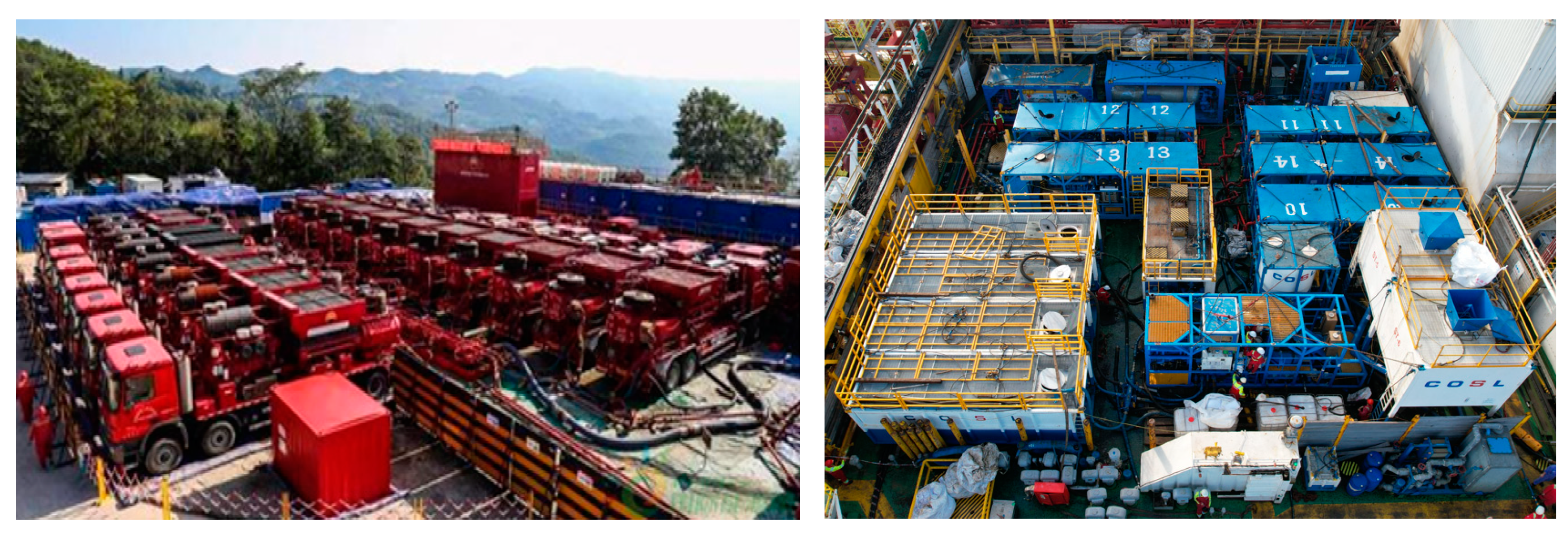
The small platform size makes it difficult to place large fracturing equipment. Onshore fracturing equipment placement is less affected by the size of the well site, and the number of fracturing equipment can be placed more than 20 suits. However, the deck area of offshore drilling platforms is small, and the load-bearing capacity of the platform is limited, and the fracturing equipment, including sand tanks, fracturing units, continuous mixing units, etc., are relatively large and heavy, and the number and location of placements are limited, so it is difficult to carry out large-scale fracturing operations on the sea [42]. The layout of onshore (Changqing oil field, China) and offshore (Weizhou oil field, China) fracturing equipment is shown in Figure 1.

3. Materials and Methods

3.1. Experimental Samples

The experiment selects 40–70 mesh quartz sand as aggregate, silicate cement as binder, and added water, defoamer, water reducer, iron powder, and bentonite clay in turn(Tianjin, China). The mixed materials are poured into the cement net mortar mixer(Haian, China) for low-speed mixing for 120 s, then resting for 15 s, and then in high-speed mixing for 120 s. Then the cement mortar is poured into standard molds, and the surface is scraped smooth and then placed on the vibrating table. It is vibrated for 30 s, rests for 15 s, is vibrated again for 30 s, and then placed in a constant temperature and humidity maintenance room to maintain the same conditions, with a maintenance cycle of 28 days. Based on the different ratios of cement mortar, 16 artificial rock samples are prepared, and the 6th formula with mechanical properties closest to reservoir shale is ultimately selected as the experimental rock sample. The size of the rock sample used in the experiment is 30 cm × 30 cm. The different proportions and basic physical parameters of artificial rock samples are shown in Table 1.
The final test program parameters of the selected artificial rock samples are shown in Table 2.
At the same time, a seawater-based integrated variable viscosity fracturing fluid is also used in the experiment, and its system composition is as follows: 0.2–0.8% emulsified thickener + 0.5% multi-functional additives + 0.05–0.08% liquid gel breaker, in which the multi-functional additives are composed of an anti-swelling agent, a complexing agent, and a cleanup agent(Tianjin, China). The action mechanism of the main agent emulsified thickener is to add a strong complexing agent, R1, in the cross-linking system to inhibit polyhydroxy metal ions, control the generation rate of hydrated metal ions, and meanwhile add polyhydroxy alcohol, R2, to coordinate with the condensation of the cross-linking site in the thickener, control the rate of the cross-linking reaction between hydrated metal ions and polymers, and satisfy the condition of cross-linking obstruction at room temperature. And with the requirement of rapid release of sites when the temperature rises (>60 °C), it can delay crosslinking to reduce friction and ensure the sand-carrying performance of the reservoir under high temperature and achieve the supporting effect of the fracture grid in the reservoir. The results of its thickening experiment are shown in Table 3.

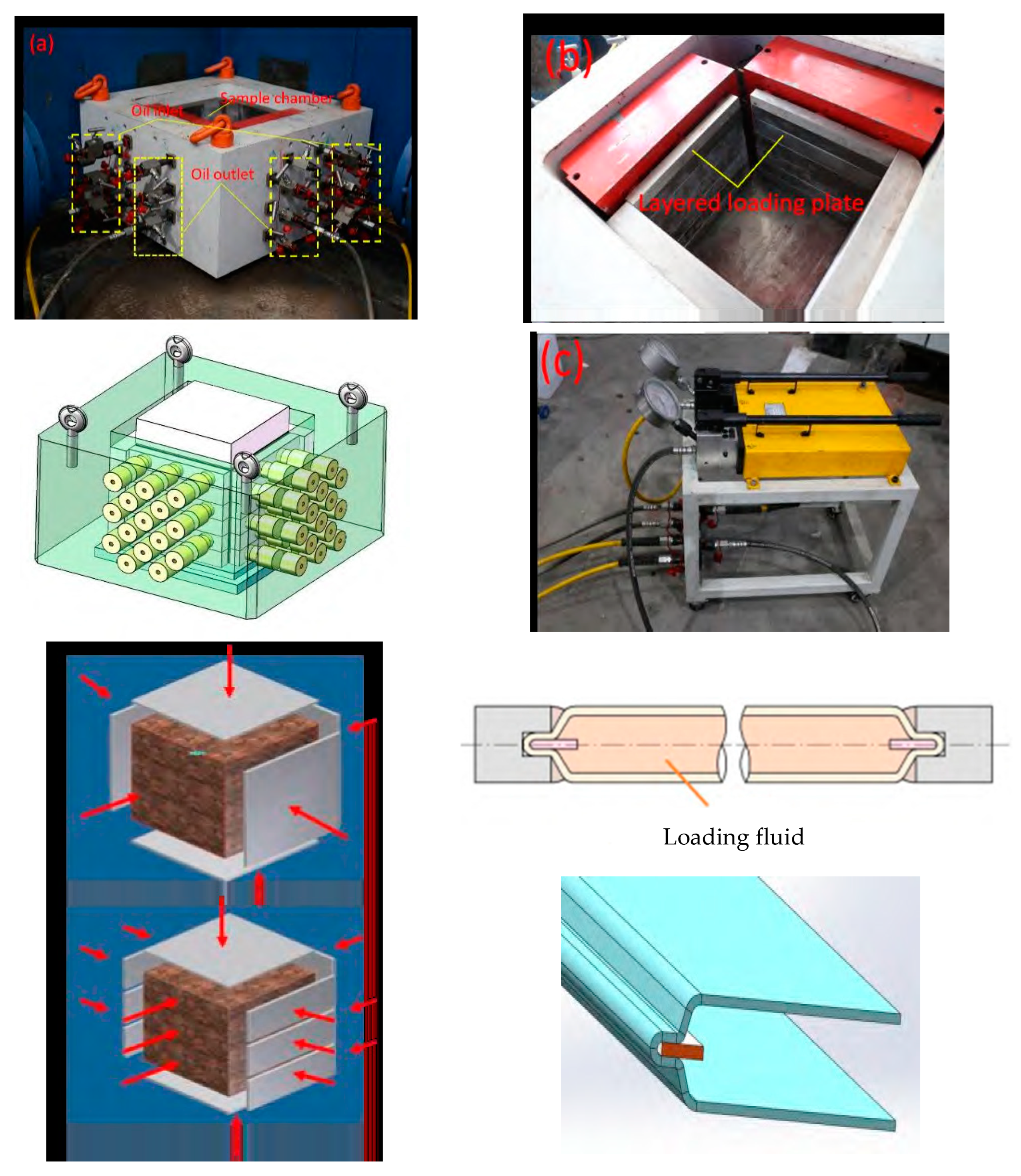
3.2. Experimental Device

A set of layered stress loading experimental devices is designed and developed independently to carry out oil shale hydraulic fracturing experiments, as shown in Figure 1. The internal dimensions of the device are 30 cm × 30 cm. By applying flexible, thin-walled, stainless steel bag-type hydraulic layered loading technology, as shown in Figure 2, and installing stress sensors on the side walls of the experimental device, it is capable of simulating the influence of different small interlayer stress differences on the longitudinal expansion pattern of the fracture, and the device is pressurized to withstand a pressure of 50 MPa in a single layer, and the maximum interlayer stress difference can be as high as 15 MPa, with a wide range of adjustment on the stress difference and a high reliability.

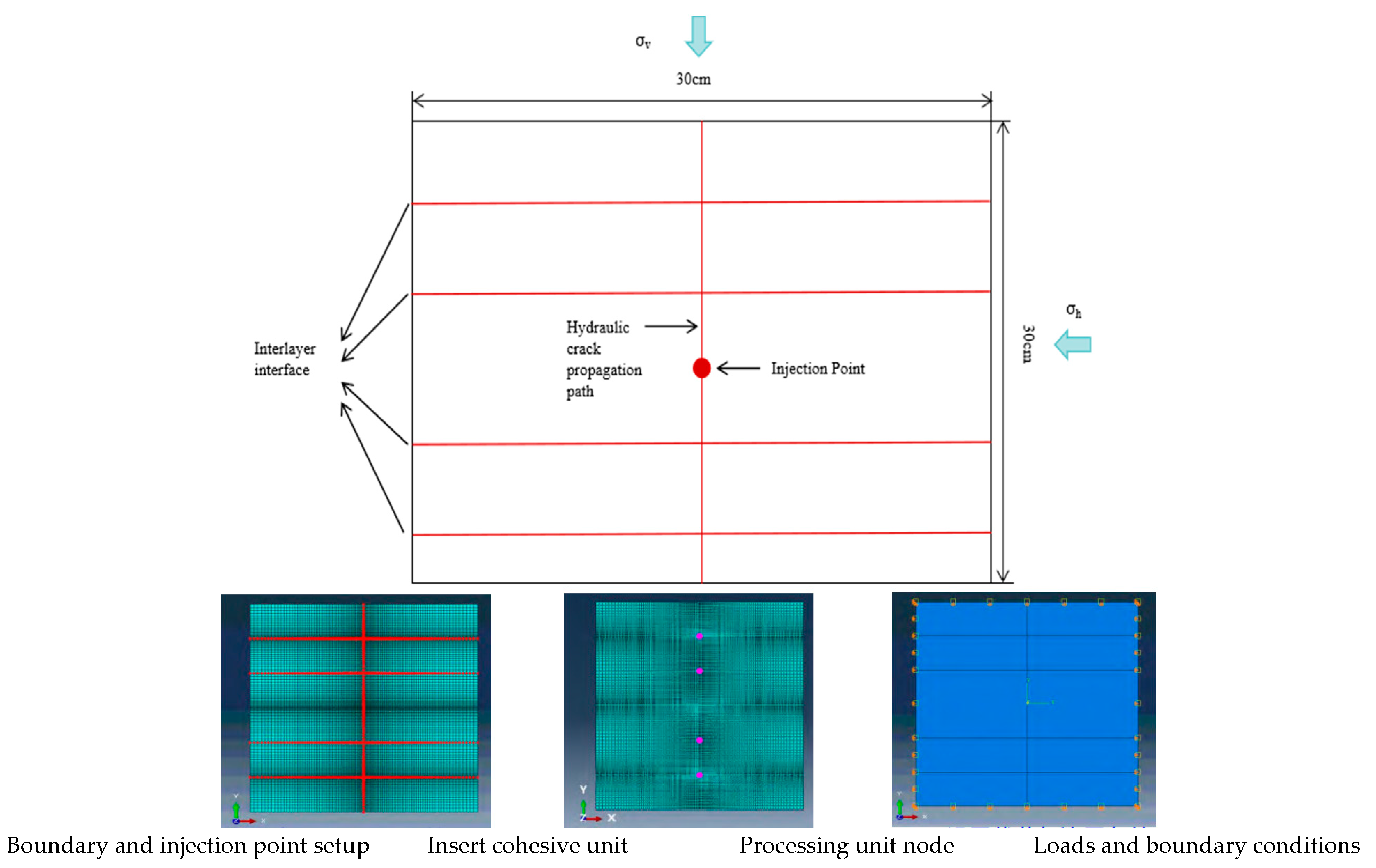
3.3. Numerical Simulation Method

According to the characteristics of the south-west Weizhou oilfield shale oil reservoir, a numerical analysis model was established based on the rupture and fracturing characteristics of low-modulus mudstone. Based on the proposed model, the key influencing factors of penetrating and expanding cracks in interbed sand-mudstone are carried out, and the effects of longitudinal lithology changes, stress difference changes, and elastic modulus changes on the extension of fracture height are analyzed. The modeling process and initial boundary conditions are shown in Figure 3 and Table 4.
The dimension of the numerical simulation is based on the lab setup where a cube with a side length of 30 cm is considered. Specifically, a 2D simplification is considered to reduce the computational load to a practical level. For the boundary condition, traction boundaries with vertical and horizontal stress magnitudes are used, while the injection point at the center of the model provides mass injection. Rectangular elements are used in the 2D mesh. Four horizontal cohesive zones are prescribed in the mesh to represent the interlayering effect. The numerical simulation strategy is designed to mimic the lab condition.

4. Results and Discussion

4.1. Experimental Results and Analysis

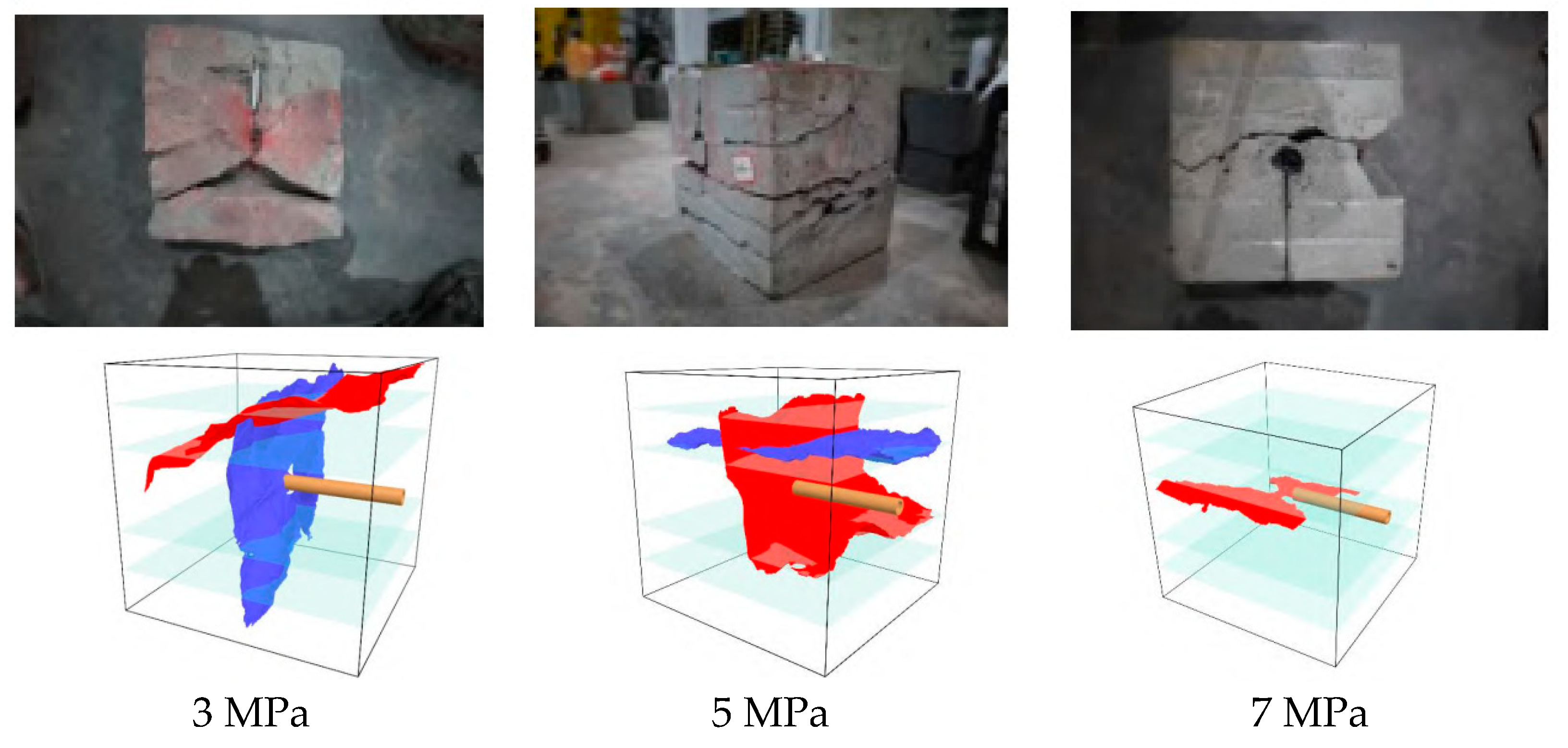
4.1.1. Influence of Different Stress Differences on Cracks

The fracture extension morphology of homogeneous rock samples under different conditions of reservoir stress difference is investigated experimentally. The viscosity of fracturing fluid used for the experiment is 5 mPa·s, the injection rate is 30 mL/min, and the fracture characteristics at the stress differences of 3, 5, and 7 MPa are tested, and the experimental results are shown in Figure 4. The results show that when the stress difference is 3 MPa, the stress shielding effect is not obvious; the main hydraulic fracture is able to traverse each small layer of various layered stress loading, and an inclined surface is formed close to the upper part with a big stress difference. When it is 5 MPa, the hydraulic fracture surface has a certain shielding, the compression fracture downward expansion is insufficient, and the hydraulic fracture only penetrates into the No. 2 and No. 3 sub-layers, and a horizontal fracture is formed between the No. 2 sub-layer with high stress and the No. 3 sub-layer with low stress. When it is 7 MPa, the hydraulic fracture is obviously blocked by the high stress, and an inclined hydraulic fracture surface is formed only in the No. 3 sub-layer with low stress. Their corresponding 3D reconstruction maps of the fractured cracks are shown in Figure 3. Based on this set of results, it is noted that, for the geomechanical condition in the south-west Weizhou shale oil reservoirs, a stress difference of 7 MPa can effectively inhibit interlayer fracture growth, while a stress difference lower than 5 MPa cannot inhibit interlayer fracture growth. This quantitative observation can serve as a hydraulic fracture interlayer growth criterion for this field.

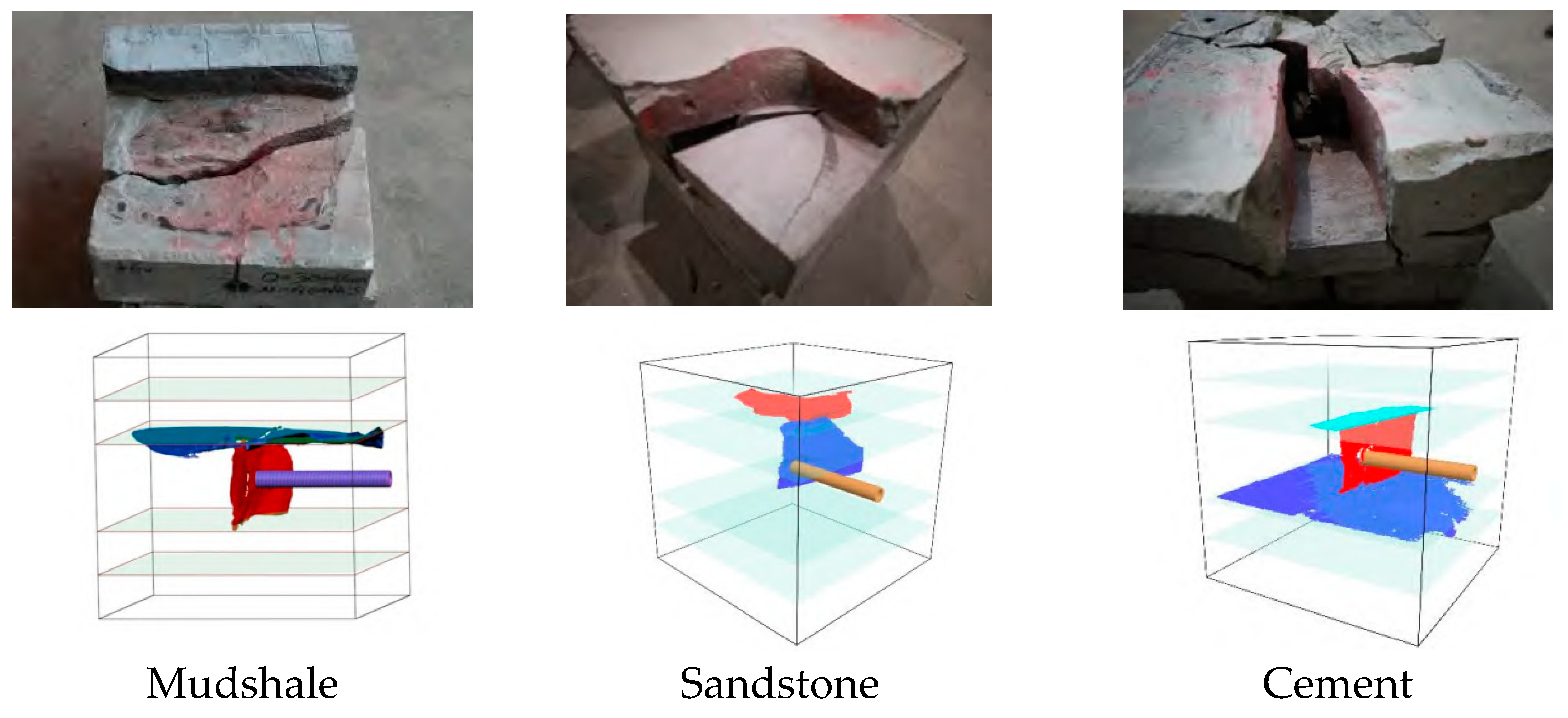
4.1.2. Influence of Different Traversed Layers on Cracks

The fracture extension pattern traversed in different sand-mudstone formations is investigated experimentally. The experimental conditions are as follows: the stress difference was 5 MPa, the viscosity of fracturing fluid is 5 mPa·s, and the injection rate is 30 mL/min, and the fracture characteristics of different traversed layers through mud shale, sandstone, and cement were tested, and the results are shown in Figure 5. The results show that when the stress difference is 5 MPa, the hydraulic fracture surface fails to traverse the upper and lower sandstone slabs and only forms a main fracture perpendicular to the wellbore in the cement layer with a low stress difference. When the intermediate shot hole location is sandstone, the rupture pumping pressure is significantly higher than that of the shot hole location, and the hydraulic fracture continues to expand to the upper cement layer after opening the sandstone layer. When the traversed layer is the cement section, the hydraulic fracture surface fails to traverse the upper and lower sandstone layers and only forms an ‘I’-shaped hydraulic fracture surface in the No. 3 small layer. The corresponding 3D reconstruction maps of the fractured cracks are shown in Figure 4. At a constant stress difference of 5 MPa, the fracture ability to traverse layers showed material-dependent behavior, where the fracture successfully propagated through cement layers but demonstrated limited traversing capability in sandstone layers, particularly when encountering sandstone boundaries, which exhibited significantly higher rupture pumping pressures compared to the initial fracture location.

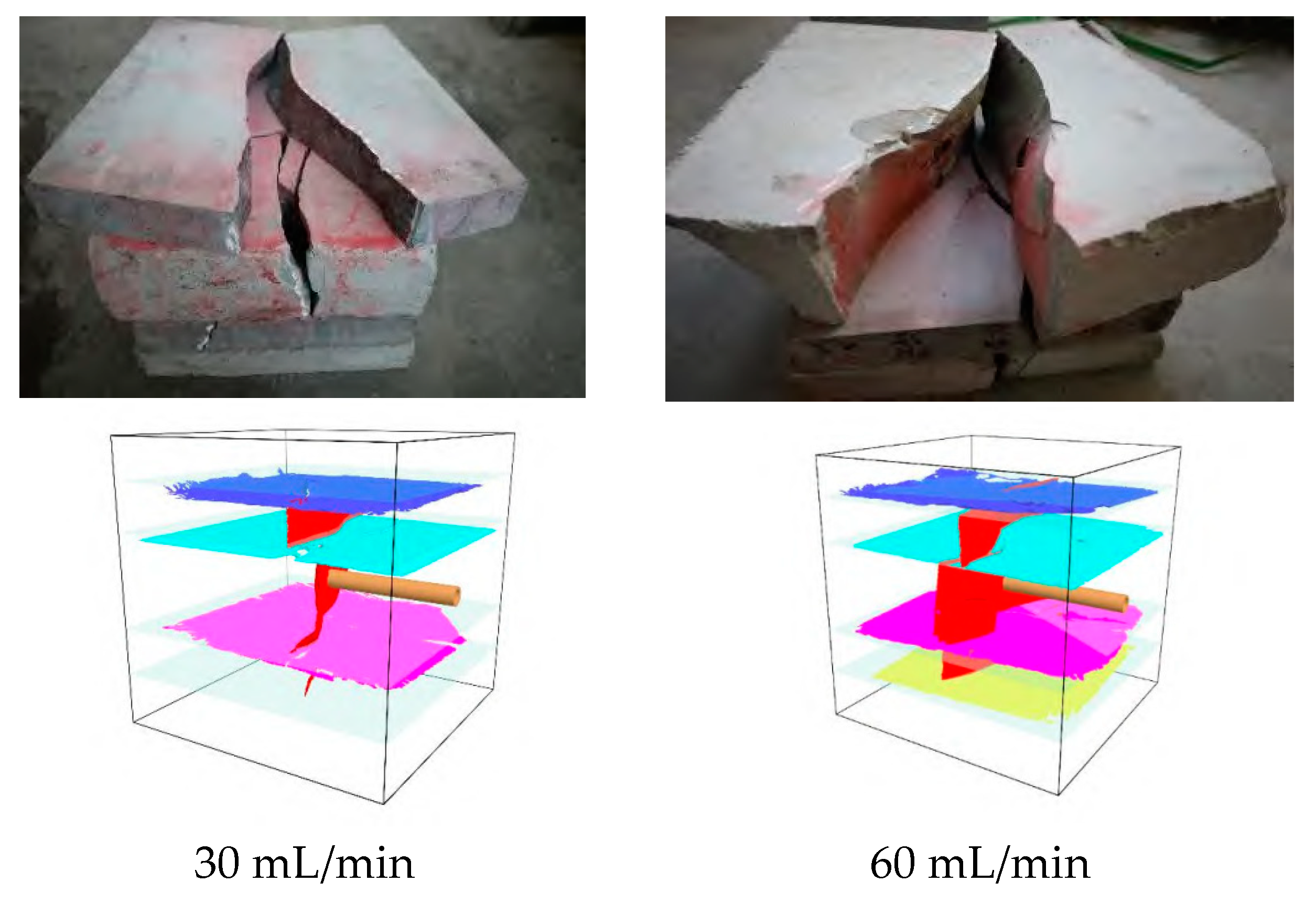
4.1.3. Influence of Fracturing Fluid Parameters on Cracks

The viscosity of the fracturing fluid is changed to 40 mPa·s, the fracture characteristics are tested at a stress difference of 5 MPa and different injection rates, and the experimental results are shown in Figure 6. The results show that after using high-viscous fracturing fluid, the cracks traverse a total of three small layers, and the fourth small layer is not completely opened, i.e., the fracturing fluid did not enter the cementation surface between the No. 4 and No. 5 layers. However, after using a high injection rate (60 mL/min), the effect of penetrating through the layers is obvious compared with that of low viscous and low rate conditions, and the experimental results showed that a total of three small layers is traversed, and both the upper and lower sandstone layers and the cementing surface between each small layer are opened. The corresponding 3D reconstruction maps of the fractured cracks are shown in Figure 5. When the fracturing fluid viscosity was increased to 40 mPa·s with a stress difference of 5 MPa, the fracture traversing capability improved significantly, particularly at higher injection rates (60 mL/min), where the fracture successfully penetrated through three layers, including both sandstone and cement interfaces, compared to the limited penetration observed under low viscosity (5 mPa·s) and low injection rate (30 mL/min) conditions.

4.2. Numerical Simulation Results and Analysis

4.2.1. Influence of Young’s Modulus on Cracks

The influence of the difference in Young’s modulus between mudstone and sandstone reservoirs on the fracture height is simulated, and the simulation results are shown in Figure 7. The results show that the mudstone layer has a strong limiting effect on the fracture height; the smaller the elastic modulus of the mudstone, the larger the width of the hydraulic fracture, and the height of the fracture will be reduced under the same volume of the injected fluid. In addition, due to the ductile toughness of the mudstone, it is not easy to form a high-stress concentration zone at the tip of the hydraulic fracture, and the fracture initiation and extension become more difficult.

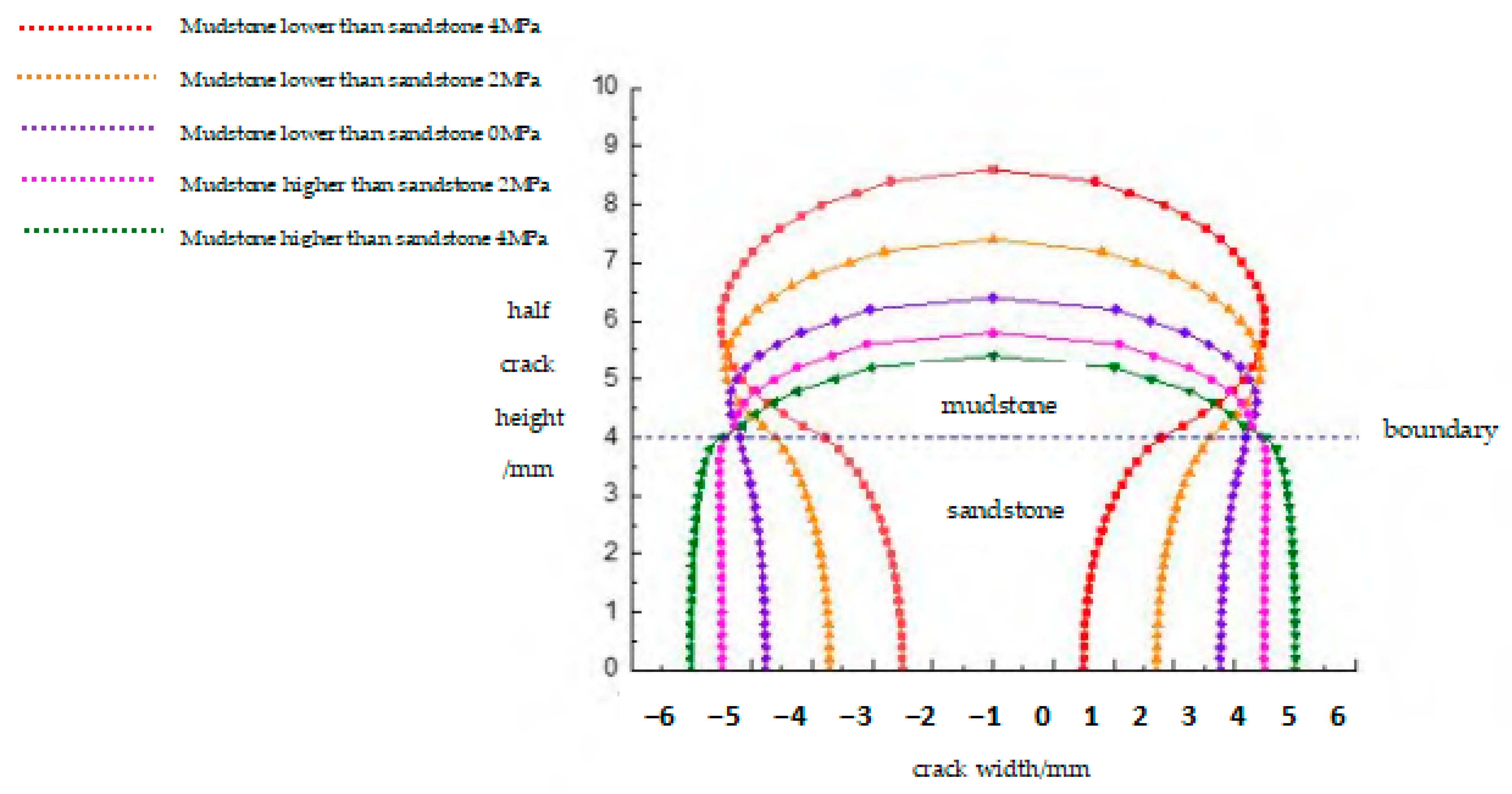
4.2.2. Influence of Minimum Horizontal Principal Stress on Cracks

The influence of the minimum horizontal principal stress difference between mudstone and sandstone reservoirs on fracture height is shown in Figure 8. The results show that the difference in the minimum horizontal principal stress of the reservoir compartment has a significant effect on the expansion of the fracture height, and when the minimum horizontal principal stress of the mudstone layer is lower than the sandstone layer, it is more favorable to the expansion of the fracture height, and vice versa; it has a stronger inhibiting effect on the fracture height.

4.2.3. Influence of Fracturing Fluid Injection Rate on Cracks

The influence of the fracturing fluid injection rate on the extension distance of the fracture height is shown in Figure 9. The results show that with the increase in the fracturing fluid injection rate from 3.0 mL/min to 7.0 mL/min, the longitudinal extension height through the layer increases significantly. With the increase in the injection rate, the fracture extension pressure gradually increased, especially when the artificial fracture extended into the interior of mudstone; the fracture extension pressure increased significantly, and the fracture extension pressure in the compartment increased by about 10 MPa when the injection rate was increased from 3.0 mL/min to 7.0 mL/min.
At the same time, through the study of the fracture expansion law through a layer in thin interbed reservoirs under different rates, it is concluded that under the condition of a 6 m3/min rate, the longitudinal expansion of fracture height through a layer is obviously suppressed, which is mainly due to the fact that after the hydraulic fracture starts cracking from the sandstone layer, when it expands to the mudstone reservoir, due to the low elasticity modulus, it will result in the increase in the fracture height expansion and the decrease in the stress concentration degree of the fracture tip, which makes it difficult to further extend the fracture. When the rate is less than 9 m3/min, the fracture extends longitudinally but does not penetrate the layer, and when the rate reaches 10 m3/min, the fracture penetrates the layer longitudinally, but the length of the fracture decreases significantly, and the simulation results are shown in Figure 10.

5. Field Application and Effect

5.1. Field Application Technology Countermeasures

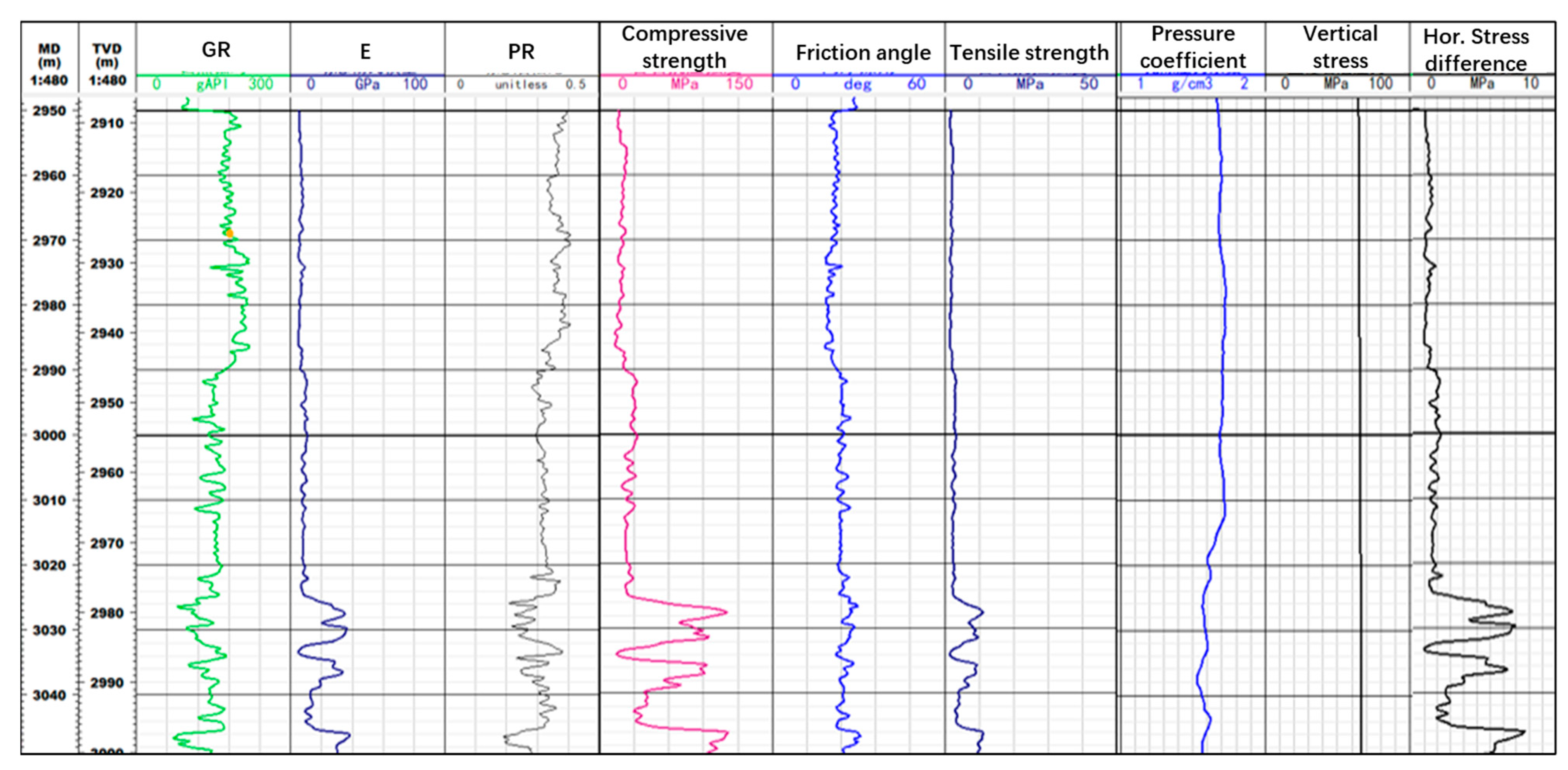
5.1.1. Select Fracturing Sweet Spots

By analyzing the horizontal two-way stress difference in the interbedded shale oil formation, the fracturing operation is focused on preferred sandy strips where the stress difference is larger, which is conducive to breaking through the shale laminae and forming complex fractures. Figure 11 shows the results of the horizontal two-way stress difference calculated according to the logging data of the interbedded shale oil formation in the south-west Weizhou oilfield well A, from which it can be seen that the well develops sandstone strips of about 1 m intermittently at the depth of 3025–3050 m, in which the horizontal two-way stress difference in the shale is 3 MPa, which is easy to form complex fractures, and the horizontal two-way stress difference in the sandstone strips is up to 8 MPa, so it is preferable to select the sandstone strips with a large stress difference for perforation and fracturing. It can form symmetric biplane joints and, at the same time, break through the shale laminations at a large rate; the cracks spread to the shale section and increase the complexity of the cracks. Therefore, three clusters of sandstone strips of 3 m in total are selected from 3027 to 3028 m, 3031 to 3032 m, and 3048 to 3049 m for the three-cluster simultaneous fracturing with the optimized cluster spacing of no more than 10 m, so as to guarantee the uniform modification and to enlarge the scope of the modification as much as possible.

5.1.2. Field Mixing Process for Seawater-Based Fracturing Fluids

Since seawater is inexhaustible for offshore platform operations, combined with continuous mixing construction, large-scale fracturing can be realized. According to the results of the model experiments, when the fracturing fluid viscosity was changed to 40 mPa·s, the effect of fracturing through the layer was obvious, so the viscosity of the fracturing fluid used for fracturing operation should be more than 40 mPa·s. Carboxymethyl hydroxypropyl guanidine gum can be used as the thickening agent of fracturing fluid. Due to the introduction of a carboxymethyl group in the molecule of hydroxypropyl guanidine gum to modify the guanidine gum to form carboxymethyl hydroxypropyl guanidine gum, the molecular group has stronger hydrophilicity, and thus it has good swelling performance. The indoor test showed that the viscosity of carboxymethyl hydroxypropyl guanidinium gum could reach 85% of the final viscosity within 3 min. At the same time, the high-temperature shear performance of the seawater-based fracturing fluids was investigated indoors, and the viscosity curves of the fracturing fluids after shearing for 2 h at 150 °C are shown in Figure 12. Seen from Figure 12, the viscosity of the seawater-based fracturing after long-time and high-temperature shear is 93 mPa·s, which meets the requirements of fracturing operation.
The seawater lifting pump is a seawater lifting system configured for offshore drilling platforms in the pile leg. Generally, the seawater lifting pump can meet the demand of a large-scale fracturing rate, and the rate can reach 30 m3/min, which can provide seawater supply for seawater-based fracturing and provide water security for realizing large-scale fracturing at sea. By applying the continuous mixing construction process, all the chemical additives in the fracturing fluid formula can be added in real time during the fracturing construction process, and real-time adjustment of various additives and fluid formulas can also be realized, which effectively improves the fracturing construction efficiency. In addition, the standby process is mud pit → mud pump → base fluid buffer tank. During fracturing operation, the mud pit of the platform is cleaned in advance, and the fracturing fluid base fluid is configured in the mud pit through the process of seawater lifting pump → filter → continuous mixing unit in advance so that in case of failures of seawater lifting pumps, filters, continuous mixing units, and other equipment, the fracturing fluid stored in the mud pit can be pumped into the base fluid buffer tank through the mud pump so as to ensure the continuity of the fracturing operation.

5.1.3. Platform Space Optimization Process

According to the results of the previous modeling experiments, a high rate is beneficial to fracturing through the layer, but due to the space limitation of the platform, the rate cannot be continuously increased, and the offshore drilling platform has a limited structure and carrying capacity, while the fracturing equipment is usually large and heavy, so it is necessary to ensure that the platform can safely carry and maintain its own balance. In terms of the equipment sizes, according to the numerical modeling results in the previous section, when the rate is greater than 6 m3/min, the fracture extension distance is longer, and when the rate is greater than 9 m3/min, the requirement of layer penetration can be achieved. In terms of the placement of offshore large-scale fracturing equipment, the placement of the equipment needs to be balanced and distributed to avoid unilateral overloading and maximize the use of platform space, and at the same time ensure that there is sufficient spacing between the equipment to facilitate the operation and maintenance of the operators. Compared with onshore oilfields, the main difference in the placement of large-scale offshore fracturing equipment is that the offshore operating environment is more complicated, and the fixing and installation of the equipment need to meet the stability requirements of the offshore environment in order to withstand the influence of waves, wind, and other factors.
Under the premise of balance and safety, the equipment is placed as close to the center of the platform as possible to ensure the average force. The side-by-side arrangement of fracturing pumps helps to shorten the water supply process between sand mixer trucks and fracturing pumps and effectively reduce the friction of the water supply pipeline. The consistent placement of buffer tanks helps to unify the observation of liquid level and effectively reduces the large difference in liquid level due to the difference in the length of the rate process. The clear division of the high-pressure and low-pressure zones effectively reduces the risk of high-pressure zones and provides safety for the operators in the low-pressure zones.

5.2. Fracturing Operation and Effect

5.2.1. Small-Scale Fracturing Operation

After connecting test equipment, fracturing equipment, test pressure, and other fracturing preparations on site, we carried out the perforating operation and found that there was no production capacity at the wellhead and then transferred to the fracturing operation. Firstly, we carried out the small fracturing operation and conducted the rate increase and decrease test. When the rate reached up to 5 m3/min, we achieved the fracture extension pressure of 62.23~69.14 MPa. At the same time, the total friction in the near-wellbore was 38.42 MPa, 30.05 MPa, and 18.2 MPa at the displacements of 5 m3/min, 4 m3/min, and 3 m3/min, respectively, and the main fracturing rate was adjusted to 6 m3/min according to the results of the mini-fracturing operation.

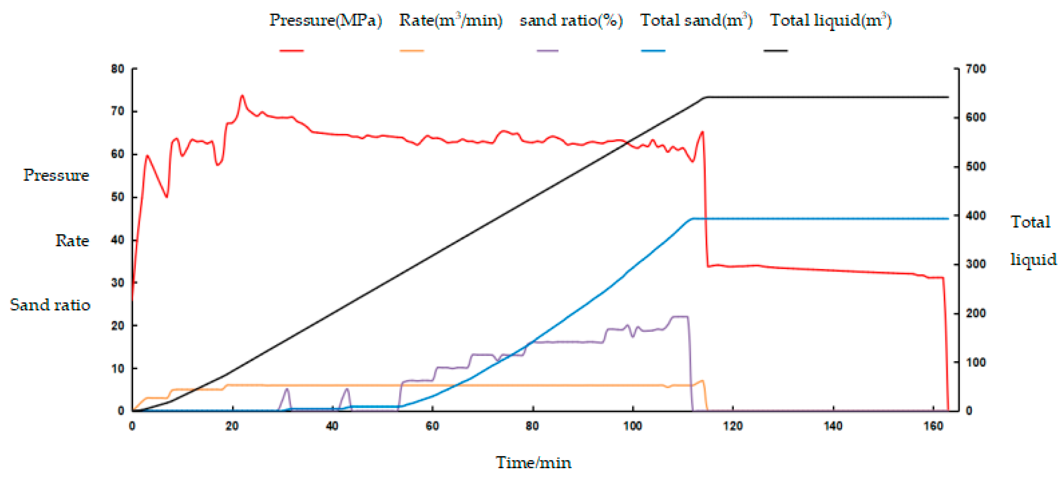
5.2.2. Main Fracturing Operation

The seawater lifting pump of the drilling platform was used to pump seawater around the platform to the continuous mixing device, and the continuous mixing device mixed seawater-based fracturing fluids on site to the fracturing pumps, and then the fracturing pumps injected at a rate of 6 m3/min, with a maximum rate of 7 m3/min. According to the pumping procedure, the cumulative total volume of fluids pumped in was 640 m3, and the total volume of sand pumped in was 45 m3, and the maximum pressure at the wellhead was more than 70 MPa, and the main fracturing operation was carried out smoothly. The operation construction was smooth, and the construction curve is shown in Figure 13.

5.2.3. Fracturing Effectiveness

In order to reduce the reservoir damage, the return discharge was started within 3 h after the end of fracturing, and the viscosity of the return discharge fluid was monitored to be 2~3 mPa·s, indicating the return discharge fluid was completely broken, the return discharge fluid was monitored to be free of proppant spitting, which effectively supported the reservoir, and the oil flower began to be seen at the early stage of flowback and gradually increased, and the daily production of crude oil was 20 m3, natural gas was 1589 m3, and the production capacity was stable. After the end of production seeking operations, post-fracturing acoustic logging was carried out, and the results of logging interpretation are shown in Figure 14. It can be seen from the figure that the acoustic amplitude, radial velocity profile, and remote detection have obvious fracture response characteristics, of which the fracture response is seen in the range of 12 m beside the remote detection wells, which indicates that the post-fracturing modification effect is good.

6. Conclusions

(1)
Aiming at the technical challenges of offshore shale oil fracturing testing, based on the characteristics of shale oil reservoirs in southwestern Weizhou, a numerical analysis model of sand-mudstone thin interlayer fracturing is established based on the study of low-modulus mudstone rupture and fracture characteristics, and a set of experimental devices for layered stress loading is designed and developed independently. Through numerical simulation and experimental testing, the key influencing factors in penetrating fracturing of shale oil were analyzed, and it was obtained that the injection of high-rate and high-viscosity fracturing fluid has a significant impact on the hydraulic fracture surface penetration. Numerical simulation analysis shows that the smaller the elastic modulus of the mudstone interlayer and the lower the minimum horizontal principal stress compared to the sandstone layer, the more favorable it is for fracture propagation.
(2)
In view of the actual well conditions of a shale oil well in the south-west Weizhou oilfield, based on the analyses of formation stress difference calculated by simulation, we have formed the supporting technical measures for large-scale fracturing of the south-west Weizhou oilfield shale oil by focusing on the selection of interlayer shale oil sweet spots, supporting the research and development of seawater-based fracturing fluids and the application of the on-line continuous mixing process, as well as the optimization of the limited space of the platform.
(3)
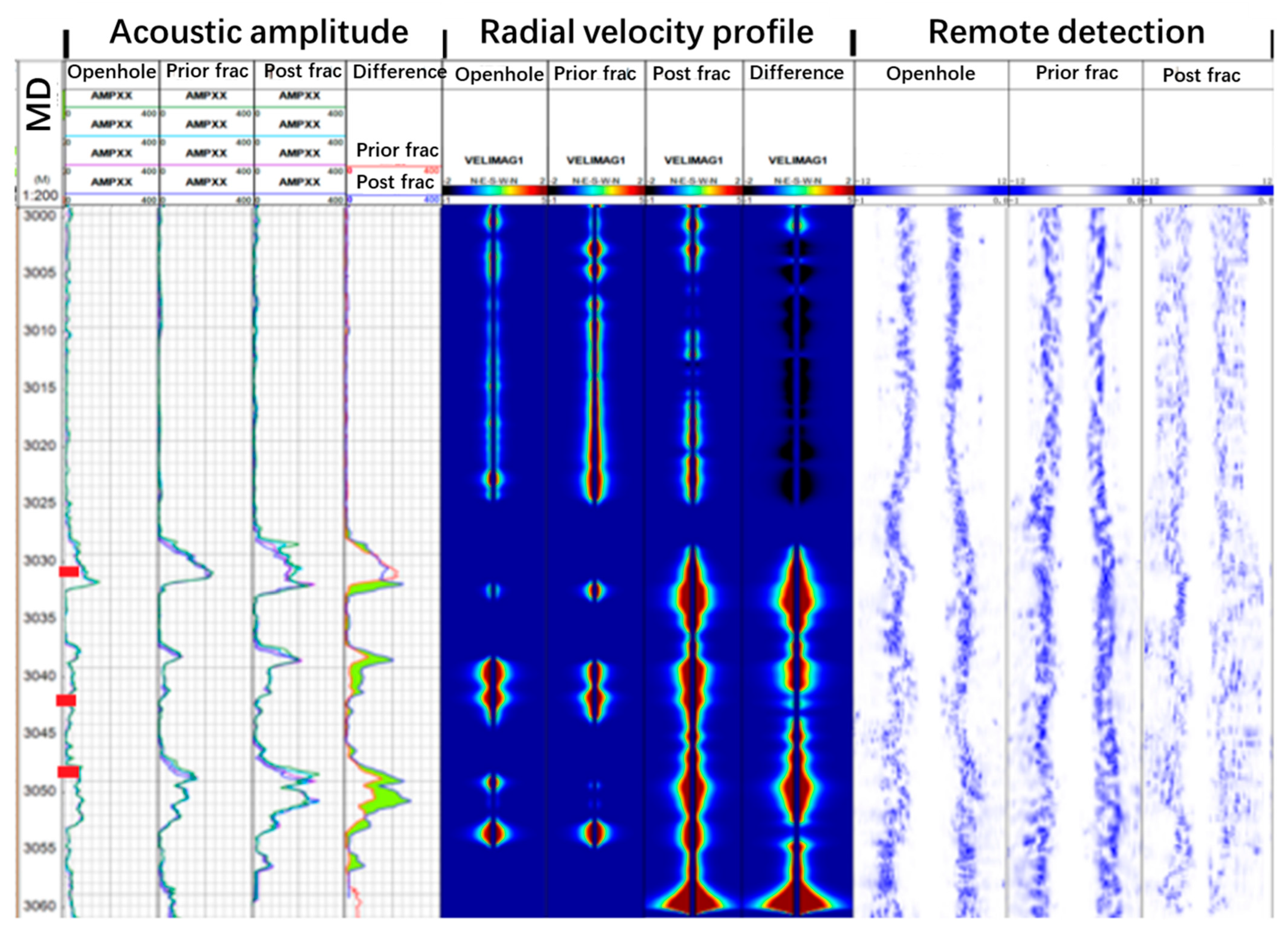
By overcoming the spatial limitation of the platform, during the site fracturing construction, the seawater lifting pump was used to extract seawater for continuous mixing fracturing fluids at the site, and two operation procedures of small-scale fracturing and main fracturing were adopted to carry out the fracturing operation of China’s first offshore shale oil well successfully. The highest injection rate reached 7 m3/min, and the results of post-fracturing acoustic logging showed obvious fracture response characteristics, with the farthest detected fracture response well distance reaching 12 m, which indicated that the post-fracturing modification effect was good and it provided a technical guarantee for the subsequent offshore shale oil fracturing construction.

Author Contributions

Conceptualization, Y.J.; Methodology, W.M. and Y.L.; Software, S.W.; Investigation, S.W.; Data curation, G.R.; Writing—original draft, G.R.; Writing—review & editing, W.M. All authors have read and agreed to the published version of the manuscript.

Funding

This work was supported by the major technology projects of CNOOC “Research on Key Technologies of Shale Oil Fracturing” (KJZH-2023-2106) and the Open Fund of State Key Laboratory of Oil and Gas Reservoir Geology and Exploitation (Southwest Petroleum University) under Grant PLN2022-16.

Data Availability Statement

Dataset available on request from the authors. The raw data supporting the conclusions of this article will be made available by the authors on request.

Conflicts of Interest

Authors Wenbo Meng and Guanlong Ren were employed by the company CNOOC Zhanjiang Branch Company. The remaining authors declare that the research was conducted in the absence of any commercial or financial relationships that could be construed as a potential conflict of interest.

References

  1. Li, Q.; Li, Q.; Cao, H.; Wu, J.; Wang, F.; Wang, Y. The fracture propagation behavior of CO2 fracturing fluid in unconventional low permeability reservoirs: Factor analysis and mechanism revelation. Processes 2025, 13, 159. [Google Scholar] [CrossRef]
  2. Li, Q.; Li, Q.; Wu, J.; Li, X.; Li, H.; Cheng, Y. Wellhead Stability During Development Process of Hydrate Reservoir in the Northern South China Sea: Evolution and Mechanism. Processes 2025, 13, 40. [Google Scholar] [CrossRef]
  3. Zhou, Q.; Jin, Z.; Yang, G.; Dong, N.; Shang, Z. Shale oil exploration and production in the U.S.: Status and outlook. Oil Gas Geol. 2019, 40, 469–477. [Google Scholar]
  4. Yang, L.; Jin, Z. Global shale oil development and prospects. China Pet. Explor. 2019, 24, 553–559. [Google Scholar]
  5. Chen, Z.; Liu, H.; Li, Y.; Shen, Z.; Xu, G. The Current Status and Development Suggestions for Shale Oil Reservoir Stimulation at Home and Abroad. Pet. Drill. Tech. 2021, 49, 1–7. [Google Scholar]
  6. Xu, W.; Xiao, M.; Sun, X.; Wang, Y.; Jia, Y. Pilot test of multi-stage fracturing technology for horizontal wells in offshore low permeability reservoirs. China Offshore Oil Gas 2017, 29, 108–114. [Google Scholar]
  7. Liu, N.; Ning, X.; Chen, Z. Research and practice of large scale fracturing technology in offshore exploration well. Chem. Eng. Oil Gas 2012, 41, 216–218+250–251. [Google Scholar]
  8. Beugelsdijk, L.; De Pater, C.; Sato, K. Experimental hydraulic fracture propagation in a multi-fractured medium. In SPE Asia Pacific Conference on Integrated Modelling for Asset Management; SPE: Calgary, AB, Canada, 2000; pp. 177–184, SPE-59419-MS. [Google Scholar]
  9. Rueda Cordero, J.A.; Mejia Sanchez, E.C.; Deane, R.; Pereira, L.C. Hydro-mechanical modeling of hydraulic fracture propagation and its interactions with frictional natural fractures. Comput. Geotech. 2019, 111, 290–300. [Google Scholar] [CrossRef]
  10. Wei, S.; Kao, J.; Jin, Y. A discontinuous discrete fracture model for coupled flow and geomechanics based on FEM. J. Pet. Sci. Eng. 2021, 204, 108677. [Google Scholar] [CrossRef]
  11. Wu, Z. Exploration of optimization of volume fracturing process parameters for intensive cutting of Daqing Gulong shale oil. Well Test. 2023, 32, 34–40. [Google Scholar]
  12. Zhang, M.; Tao, C.; Zuo, T. Key technologies and practices for reservoir stimulation of shale oil Hua H100 platform. Drill. Prod. Technol. 2023, 46, 53–58. [Google Scholar]
  13. Liu, W.; Xu, X.; Liu, C.; Chen, S.; Bai, J.; Li, Y. The stimulation mechanism and performance analysis of supercritical CO2 and hydraulic sand-carrying composite volume fracturing technology on continental shale reservoirs. Acta Pet. Sin. 2022, 43, 399–409. [Google Scholar]
  14. Zhang, Y.; Wang, L.; Liu, Y.; Zhang, J.; Zhou, D.; Ge, H. Advances and Challenges of Integration of Fracturing and Enhanced Oil Recovery in Shale Oil Reservoirs. Pet. Drill. Tech. 2024, 52, 84–95. [Google Scholar]
  15. Yue, K.; Lee, H.P.; Olson, J.E. Apparent fracture toughness for LEFM applications in hydraulic fracture modeling. Eng. Fract. Mech. 2020, 230, 106984. [Google Scholar] [CrossRef]
  16. Marco, M.; Infante-García, D.; Belda, R. A comparison between some fracture modelling approaches in 2D LEFM using finite elements. Int. J. Fract. 2020, 223, 151–171. [Google Scholar] [CrossRef]
  17. Dahi Taleghani, A.; Gonzalez-Chavez, M.; Yu, H.; Asala, H. Numerical simulation of hydraulic fracture propagation in naturally fractured formations using the cohesive zone mode. J. Pet. Sci. Eng. 2018, 165, 42–57. [Google Scholar] [CrossRef]
  18. Gordeliy, E.; Peirce, A. Implicit level set schemes for modeling hydraulic fractures using the XFEM. Comput. Methods Appl. Mech. Eng. 2013, 266, 125–143. [Google Scholar] [CrossRef]
  19. Olson, J.E. Multi-fracture propagation modeling: Applications to hydraulic fracturing in shales and tight gas sands. In Proceedings of the 42nd U.S. Rock Mechanics Symposium (USRMS), San Francisco, CA, USA, 29 June–2 July 2008; p. ARMA-08-327. [Google Scholar]
  20. Roodhart, L.P.; Davies, D.R. Relation Between Chemistry and Flow Mechanics of Borate Cross linked Fracturing Fluids. SPE Prod. Facil. 1993, 8, 165–170. [Google Scholar]
  21. Mack, M.; Elbel, J.L. Hydraulic Fracture Orientation and Pressure Response During Fracturing of Producing Wells. Rock Mech. 1994, 175, 183. [Google Scholar]
  22. Alohaly, M.; BinGhanim, A.; Rahal, R.; Rahim, S. Seawater Fracturing Fluid Development Challenges: A Comparison Between Seawater-Based and Freshwater-Based Fracturing Fluids Using Two Types of Guar Gum Polymers. In Proceedings of the SPE Kingdom of Saudi Arabia Technical Symposium and Exhibition, Dammam, Saudi Arabia, 25–28 April 2016; p. SPE-182799-MS. [Google Scholar]
  23. Bao, W.; Wang, X.; Guo, B.; Chen, L.; Liu, H.; Li, M. Research and application of high temperature seawater-based fracturing fluid. Fault-Block Oil Gas Field 2017, 24, 434–436. [Google Scholar]
  24. Yang, Q. Construction and Mechanism of SiO2 Nanoparticle Enhanced Seawater Based Heat Resistant Clean Fracturing Fluid. Master’s Thesis, China University of Petroleum (East China), Qingdao, China, 2020. (In Chinese). [Google Scholar]
  25. Parker, M.; Slabaugh, B.; Walters, H.; Weaver, J.; Hanes, R. New hydraulic fracturing fluid technology reduces impact on the environment through recovery and reuse. In Proceedings of the SPE/EPA/DOE Exploration and Production Environmental Conference, San Antonio, TX, USA, 10–12 March 2003; p. SPE-80590-MS. [Google Scholar]
  26. Smirnov, N.; Li, K.; Skryleva, E.; Pestov, D.; Shamina, A.; Qi, C.; Kiselev, A. Mathematical Modeling of Hydraulic Fracture Formation and Cleaning Processes. Energies 2022, 15, 1967. [Google Scholar] [CrossRef]
  27. Kang, W.; Mushi, S.J.; Yang, H.; Wang, P.; Hou, X. Development of smart viscoelastic surfactants and its applications in fracturing fluid: A review. J. Pet. Sci. Eng. 2020, 190, 107107. [Google Scholar] [CrossRef]
  28. Li, C. Introduction of New Trend of Oil and Gas Well Test Technology and Its New technology. Well Test. 2016, 25, 56–58+77–78. [Google Scholar]
  29. Shao, L. Integration technology for low permeability reservoir fracturing flowback. Nat. Gas Oil 2013, 31, 59–60, 65. [Google Scholar]
  30. Guo, S. Perforation-Fracturing-Well Test Integrated Tech on Semi Submersible Drilling Platform. Well Test. 2011, 20, 70–71+74+78. [Google Scholar]
  31. Li, J. Application of combined technology of composite perforation and APR testing tool. Well Test. 2012, 21, 36–37. [Google Scholar]
  32. Pandey, V.J.; Burton, R.C.; Nozaki, M. Evolution of Frac-Pack Design and Completion Procedures for High-Permeability Gas Wells in Subsea Service. In Proceedings of the SPE Hydraulic Fracturing Technology Conference, The Woodlands, TX, USA, 3–5 February 2015; p. SPE-168636-MS. [Google Scholar]
  33. Lian, Z.; Zhang, Y.; Zhao, X.; Ding, S.; Lin, T. Mechanical and mathematical models of multi-stage horizontal fracturing strings and their application. Nat. Gas Ind. B 2015, 2, 185–191. [Google Scholar] [CrossRef]
  34. Wang, Y.; Hou, B.; Wang, D.; Jia, Z. Features of fracture height propagation in cross-layer fracturing of shale oil reservoirs. Pet. Explor. Dev. 2021, 48, 402–410. [Google Scholar] [CrossRef]
  35. Cui, Z.; Hou, B.; Fu, S.; Lv, J. Fractures cross-layer propagation characteristics of integrated fracturing in shale oil tight reservoir. Fault-Block Oil Gas Field 2021, 48, 402–410. [Google Scholar]
  36. Li, M.; Chen, L.; Bao, W.; Shen, J.; Zhao, J. Application of Instant Dissolved Seawater Based Fracturing Fluids in Bohai Oilfield. Offshore Oil 2022, 42, 45–48. [Google Scholar]
  37. Xiong, J.; Zhao, Z.; An, Q.; Wang, S. Synthesis and Performance Evaluation of Zwitterion Guar for High Temperature Seawater Base Fracturing Fluid. Oilfield Chem. 2018, 35, 401–405+410. [Google Scholar]
  38. Ye, D.; Wang, S.; Cai, Y.; Ren, Y.; Luo, C. Application of continuously mixing fracturing fluid and such flow process. Nat. Gas Ind. 2013, 33, 47–51. [Google Scholar]
  39. Wu, W.; Liu, Y.; Yi, D.; Xiong, Y. Application of technology continuous mixing fracturing fluid on large-scale fracturing. Chem. Eng. Oil Gas 2016, 45, 57–60. [Google Scholar]
  40. Peng, P.; Xun, Y.; Wang, Y. Current Status and Development of Fracturing Fluid Continuous Mixing Equipment. Petro Chem. Equip. 2016, 19, 15–17. [Google Scholar]
  41. Zhao, Z.; Zhang, C.; Xu, G.; Li, X.; Li, S. Optimized design and application of fracturing string for offshore low porosity and low permeability reservoirs. China Offshore Oil Gas 2013, 25, 83–86. [Google Scholar]
  42. Yao, F.; Cao, B.; Wang, S.; Hu, Z.; Xia, Y. Application of Secondary Sand Fracturing Technique in Offshore Low Porosity and Permeability Sandstone Gas Reservoir. Sci. Technol. Eng. 2020, 20, 5615–5621. [Google Scholar]
  43. NB/T 14003.3-2017; Shale Gas-Fracturing Fluid-Part 3: Performance Index and Evaluation Methods for Fracturing Fluid Blended on-the-Fly. National Energy Administration: Beijing, China, 2017.
Figure 1. Layout of onshore (left) and offshore (right) fracturing equipment.
Energies 18 02007 g001
Figure 2. Transition from uniform stress to layered stress loading mode, (a) External structure of the device, (b) Internal structure of the device; (c) Hydraulic pumping unit.
Energies 18 02007 g002
Figure 3. Numerical modeling process.
Energies 18 02007 g003
Figure 4. Characteristic morphology and 3D reconstruction of cracks under different stress differences.
Energies 18 02007 g004
Figure 5. Characteristic morphology and 3D reconstruction of cracks under different traversed layers.
Energies 18 02007 g005
Figure 6. Characteristic morphology and 3D reconstruction of cracks under different fluid rates.
Energies 18 02007 g006
Figure 7. Influence of different Young’s modulus on fracture heights.
Energies 18 02007 g007
Figure 8. Cracks height extension distance under different minimum horizontal principal stresses.
Energies 18 02007 g008
Figure 9. Cracks height extension distance under different fracturing fluid rates.
Energies 18 02007 g009
Figure 10. Extension distance of thin interbedded reservoir through layer at different rates.
Energies 18 02007 g010
Figure 11. Calculation results of horizontal two-way stress difference in well A.
Energies 18 02007 g011
Figure 12. Experimental results of high-temperature shear performance of seawater-based fracturing fluids.
Energies 18 02007 g012
Figure 13. Main fracturing construction curve for well A.
Energies 18 02007 g013
Figure 14. Interpretation of post-fracturing casing sonic logging. Perforated intervals are indicated in red in three places in the figure.
Energies 18 02007 g014
Table 1. Different proportions and basic physical parameters of artificial rock samples.
No.Cement–Sand RatioWater–Cement Ratio/%Water Reducing Agent/%Weighting Agent/%Bentonite/%UCS/MPaYoung’s Modulus/MPaTensile Strength/MPaFracture Toughness/MPa.m0.5
13:122.500099.2322,7102.770.44
23:1250.15581.4818,8101.860.29
33:1300.2101050.5712,0001.790.26
43:1350.3151562.2814,5801.970.25
52:122.50.1101586.7419,9602.380.33
62:1250151064.2515,0102.230.40
72:1300.30556.3613,2801.610.25
82:1350.25052.3012,3901.520.21
91:122.50.215530.7876501.210.27
101:1250.310050.0511,8901.680.26
111:1300.151547.2211,2701.400.28
121:1350.201038.5593601.770.34
131:222.50.351032.4980301.540.30
141:2250.201535.3886601.270.24
151:2300.115041.4610,0001.310.26
161:235010534.5184701.260.21
Table 2. Test experimental parameters of the artificial rock samples.
Stress Parameters
σ v
MPa
σ h
MPa
σ H
MPa
Mudshale282030
Sandstone282535
Table 3. Test experimental results of thickening rate.
Concentration
%
Base Liquid Viscosity
mPa·s
(30 °C Water Bath)
Thickening Rate
%
Industry Standards [43]
5 min240 min
0.233.585.7≥85%
0.318.121.086.2
0.42731.286.5
0.532.537.486.9
0.645.652.387.2
Table 4. Initial boundary parameters of the numerical model.
Parameter CategoryParameter NameValue
Rock mechanical propertiesYoung’s modulus (GPa)25
Poisson’s ratio0.25
GeostressVertical geostress (MPa)50
Maximum horizontal geostress (MPa)55
Minimum horizontal geostress (MPa)45
Fracturing parametersFracturing fluid viscosity (mPa·s)5
Pumping rate (m3/min)3
Disclaimer/Publisher’s Note: The statements, opinions and data contained in all publications are solely those of the individual author(s) and contributor(s) and not of MDPI and/or the editor(s). MDPI and/or the editor(s) disclaim responsibility for any injury to people or property resulting from any ideas, methods, instructions or products referred to in the content.

