Article

A Coordinated Control Strategy for a Coupled Wind Power and Energy Storage System for Hydrogen Production

1
Hebei Branch, China Nuclear Power Engineering Co., Ltd., Shijiazhuang 050000, China
2
School of Electric Engineering, Hebei University of Science and Technology, Shijiazhuang 050027, China
*
Author to whom correspondence should be addressed.
Energies 2025, 18(8), 2012; https://doi.org/10.3390/en18082012
Submission received: 25 March 2025 / Revised: 6 April 2025 / Accepted: 7 April 2025 / Published: 14 April 2025
(This article belongs to the Section A5: Hydrogen Energy)

Abstract

:
Hydrogen energy, as a medium for long-term energy storage, needs to ensure the continuous and stable operation of the electrolyzer during the production of green hydrogen using wind energy. In this paper, based on the overall model of a wind power hydrogen production system, an integrated control strategy aimed at improving the quality of wind power generation, smoothing the hydrogen production process, and enhancing the stability of the system is proposed. The strategy combines key measures, such as the maximum power point tracking control of the wind turbine and the adaptive coordinated control of the electrochemical energy storage system, which can not only efficiently utilize the wind resources but also effectively ensure the stability of the bus voltage and the smoothness of the hydrogen production process. The simulation results show that the electrolyzer can operate at full power to produce hydrogen while the energy storage device is charging when wind energy is sufficient; the electrolyzer continuously produces hydrogen according to the wind energy when the wind speed is normal; and the energy storage device will take on the task of maintaining the operation of the electrolyzer when the wind speed is insufficient to ensure the stability and reliability of the system.

1. Introduction

As conventional energy sources are gradually being depleted and environmental pollution continues to worsen, global sustainable development is encountering significant challenges. The transition of energy systems has emerged as a key strategy to achieve carbon neutrality, with the reduction of fossil fuel usage and its replacement by renewable energy sources for electricity generation being recognized as one of the most effective solutions [1]. However, despite the rapid expansion of renewable energy, a lack of market integration space has increasingly become a major obstacle hindering the widespread adoption of renewable energy [2]. Green hydrogen, a form of hydrogen energy storage, is being actively developed in line with global efforts to achieve carbon neutrality, with a particular focus on long-duration peak shaving energy storage [3]. Hydrogen energy storage holds promise due to its high energy density, long-duration storage capability, ease of transportation, and zero-carbon emissions. Nonetheless, challenges related to its low energy density and flammability and the complexities involved in its storage and transport present substantial barriers [4,5]. Wind-powered hydrogen production is a method of generating green hydrogen that can effectively address the issue of wind energy curtailment and enhance renewable energy consumption capacity. Additionally, wind farms are typically located in remote areas, reducing the risks associated with hydrogen’s flammability in urban settings [6].
Green hydrogen production via wind power is pivotal for the transition of the energy sector and predominantly achieved through water electrolysis [7]. Additionally, the integration of wind power with electrochemical energy storage systems not only mitigates fluctuations but also stabilizes energy output [8]. Hence, rapid-response energy storage systems are crucial for ensuring the consistent operation of wind-powered hydrogen production systems. At present, hydrogen energy storage has garnered significant attention within renewable energy generation, especially when coupled with integrated energy systems, offering a promising pathway to decarbonize regional energy frameworks [9]. Ref. [10] investigates the role of hydrogen storage in long-duration and seasonal energy storage, highlighting its ability to smooth out fluctuations from renewable sources and enable inter-seasonal and inter-monthly energy exchange. Hybrid energy storage solutions, such as combining hydrogen storage with battery storage, can enhance the leveling of renewable energy and address both short-term and medium- to long-term system imbalances [11]. Ref. [12] explores a hydrogen-centric integrated energy system that utilizes hydrogen storage across various timescales to manage short- and medium- to long-term power generation and consumption discrepancies. Ref. [13] illustrates how multi-modal hydrogen energy use can significantly reduce supply–demand mismatches and enhance capacity for renewable energy consumption. The aforementioned research primarily focuses on the optimization and control of hydrogen-based energy storage systems, while addressing the system’s short-term control dynamics remains an essential area for further study.
The hydrogen production process from wind power depends on the energy storage system’s charge and discharge characteristics, as well as the converter control strategy within the wind storage system. These elements are crucial for maintaining the stability of the wind-storage-coupled hydrogen production system and ensuring smooth hydrogen generation [14]. Thus, studying the control strategies for wind storage hybrid systems for hydrogen production is of significant practical value in solving the issue of photovoltaic energy consumption and enhancing the stability of hydrogen production systems [15,16]. A considerable amount of research has been dedicated to the control strategies of wind-powered hydrogen production systems. Ref. [17] examines the energy transfer mechanisms and numerical simulation techniques for electricity to electricity and gas to electricity systems within hydrogen energy storage systems (HESS). The integrated HESS model presented includes components like alkaline electrolyzers, high-pressure hydrogen storage tanks, and proton exchange membrane fuel cells. However, the energy transfer mechanisms associated with power generation measurements must also be incorporated into the model. Ref. [18] introduces a method for optimally selecting a wind–hydrogen hybrid system that combines regenerative wind farms with green hydrogen production aimed at optimizing grid connection control and hydrogen generation. Nevertheless, using a purely wind-powered grid-connected system for hydrogen production may overlook the dynamics of wind power, potentially compensating for wind variability by purchasing electricity, which in turn increases costs. Ref. [19] proposes an energy management strategy for a hybrid system combining wind power, hydrogen production, fuel cells, and supercapacitors, taking into account the system’s various operational modes. However, the increased complexity of the control unit could lead to frequent mode switching, introducing potential risks and destabilizing the system’s operation. Ref. [20] presents a control strategy for a wind–hydrogen coupled generation system that addresses wind power volatility and grid abandonment issues, effectively smoothing DC bus voltage fluctuations using a combination of wind turbines, electrolyzers, fuel cells, and supercapacitors. Ref. [21] introduces a capacity allocation method aimed at utilizing hydrogen generation systems to absorb wind energy curtailment, determining the optimal allocation of capacity using interval optimization theory. However, methods utilizing hydrogen storage to absorb wind power, as discussed in Refs. [20,21], have practical limitations due to the long startup times of electrolyzers and fuel cells, necessitating a focus on ensuring the smooth operation of the hydrogen storage system. Ref. [22] suggests an override control strategy for wind–hydrogen coupled systems in wind farms with poor tracking accuracy of planned outputs, inadequate regulation of the energy storage system, and significant output power fluctuations. The strategy relies on the hydrogen storage system’s state, ultra-short-term predicted power, and day-ahead planned output, devising a corresponding regulation strategy. Ref. [23] introduces a hybrid energy conversion system based on wind, photovoltaic, and hydrogen power generation, outlining an AC-connected microgrid scheme to address the intermittent nature of wind and solar resources while proposing a control strategy to coordinate power flow between different energy sources and storage units, thereby improving the overall operation of wind and solar power generation systems. Despite the proposed strategies in Refs. [22,23], further development of more comprehensive control strategies is needed, integrating both generation and load measurement characteristics.
Considering the instability of the DC bus and the unsatisfactory hydrogen production in wind-coupled hydrogen systems when subject to disturbances like environmental changes, we propose an enhanced model for wind-powered hydrogen production. This model integrates a comprehensive wind power generation system, a lithium-ion-battery-based energy storage system, and a proton exchange membrane (PEM) electrolyzer [24,25,26]. In this framework, a maximum power point tracking (MPPT) control strategy is employed to continuously track wind power output and maximize energy utilization. Additionally, an adaptive coordination control mechanism is introduced to ensure both power balance stability and smooth hydrogen production. The system’s hydrogen production and storage capabilities are analyzed across four operational modes, as shown in the schematic diagram in Figure 1. Finally, simulations and testing are conducted on the MATLAB 2023b/Simulink platform to verify the effectiveness of the proposed control strategy.

2. Methodology of the Control Strategy

2.1. Structure of Wind Power Coupled Hydrogen Production System

The wind power integrated hydrogen production control system analyzed in this paper consists primarily of a wind turbine, a permanent magnet synchronous generator, a PEM electrolyzer, and a battery storage system. The overall configuration of this system is depicted in Figure 2.

2.2. Wind Turbine System Modeling

Wind turbines capture wind energy [27] as follows:
P m = 1 2 C p λ , β ρ A v 3
where Pm is the output power of the wind turbine; Cp(λ, β) is the power coefficient; ρ is the air density; A is the area swept by the wind turbine blades; and v is the wind speed. The wind energy capture factor is [27]
C p λ , β = 0.5276 116 λ 1 0.4 β 5 e 21 λ 1 + 0.0068 λ
1 λ 1 = 1 λ + 0.08 β 0.035 β 3 + 1
where β is the wind turbine pitch angle, λ1 is an intermediate variable, and λ is the wind turbine blade tip speed ratio:
λ = R m ω m v
We note that the tip speed ratio is positively correlated with the impeller radius (Rm) and the wind turbine angular velocity (ωm).

2.3. Direct-Drive Permanent Magnet Synchronous Generator Model

Assuming that the permanent magnet of the permanent magnet synchronous generator (PMSG) is a completely symmetrical structure, then the rotor equation of motion of the PMSG can be expressed as
T m T e D Δ ω r = J d Δ ω r d t
T m = P m ω
T e = P e ω r = 3 2 N wp I wq L w q L w d I w d + ψ f = 3 2 N wp I wq ψ f
where Tm and Te are the mechanical torque and electromagnetic torque of the PMSG, respectively. Δωr, ωr, and ω are the electrical angular velocity increment, the electrical angular velocity, and the rotor mechanical angular velocity of the PMSG, respectively. J and D are the rotor moment of inertia and the damping coefficient of the PMSG, respectively. Nwp is the number of pole pairs of the PMSG, and Iwq and Iwd are the q-axis and d-axis equivalent currents of the PMSG, respectively. ψf is the main magnetic chain of the permanent magnet, and Lwd and Lwq are the d-axis and q-axis equivalent inductances of the PMSG, respectively.
Among them, the PMSG electromagnetic torque equations and the voltage equations in the d and q coordinate system are shown in the following figure of Equations (8)–(10):
u d = R s d i d L d d i d   d t + ω s L q i q
u q = R s i q L q d i q   d t ω s L d i d + ω ψ f
T c = 3 2 n p ψ f i q + L d L q i d i q
where np is the number of pole pairs; ud, uq, id, and iq are the stator d- and q-axis voltages and currents, respectively; Rs, Ld, and Lq are the stator resistances and the d- and q-axis inductances, respectively; ωs is the electric angular frequency; and ψs is the magnetic chain of the permanent magnet.

2.4. Modeling of the PEM Electrolyzer System

The PEM hydrogen production electrolyzer voltage model can be modeled as follows [28,29]:
U e l = U o c + U a c t + U o h m
U o c = U 0 + R T e l 2 F l n P H 2 P O 2 0.5 α H 2 O
U 0 = 1.229 0.009 T e l 298
U a c t = R T e l 2 α F l n i i 0
U o h m = i R o h m
R o h m = t m σ m
where U0 is the standard electric potential (V); R is the gas constant; Tel is the temperature of the electrolyzer; α H 2 O is the water activity between the anode and the electrolyte, which takes the value of 1; Uact is the activation overvoltage; α is the transfer coefficient; i is the current density (A/cm2); i0 is the exchange current density (A/cm2); Uohm is the ohmic overvoltage; Rohm is the film resistance; tm is the film thickness; σm is the membrane resistivity, which is related to the temperature and the water content; and the formula is expressed as follows:
σ m = 0.00514 λ m 0.00326 exp 1268 1 303 1 T e l

2.5. Energy Storage Battery Establishment

In this paper, a generic equivalent circuit model of the storage battery is selected [30]. The generic equivalent schematic is shown in Figure 3, which is constructed using a series connection of a controlled voltage source Eb as well as an equivalent resistance Req.
Based on the internal electric field state of the storage battery, we can learn the following expression for the controlled voltage source Eb of Figure 3:
E b = E 0 K Q Q 0 t I b d t + A exp B 0 t I b d t
In addition, the physical parameters and physical meanings of each physical parameter of the generalized equivalent circuit model of the battery are shown in Table 1 below.
As an important parameter of the energy storage battery, the charge state can not only determine the remaining capacity of the battery in real time but also determine the battery’s state (normal, over-charge, over-discharge) according to its numerical size. The battery’s life can be effectively extended by setting the charge state of the battery in a reasonable way. The expression of the battery charging state SOC is as follows:
S O C = S O C 0 0 t I b d t Q
where SOC0 is the initial state of charge.

2.6. Wind Turbine Maximum Power Tracking

To optimize the utilization of wind energy and ensure that the wind turbine’s output power meets the hydrogen production load requirements, it is essential to implement a control strategy that enables the system to track the maximum power point of the wind energy. For variable-speed wind turbines, maximum power point tracking (MPPT) techniques are typically classified into two main categories: the optimal characteristic curve method and the optimization-seeking algorithms [31]. Among these, the optimal tip speed ratio method (based on the characteristic curve) and the hill climbing search method (from the optimization techniques) are the most commonly employed. The optimal tip speed ratio method, using a proportional-integral (PI) controller, can maintain the actual tip speed ratio close to the optimal value, which is highly effective and responsive when wind speed measurements are precise. However, due to challenges in maintaining accurate wind speed measurements in practical applications, this method may not always keep the tip speed ratio within the ideal range, necessitating additional compensation mechanisms.
The control principle of the power feedback method is simple and clear, and the effect is better, so it has high application value in practical applications. Compared with the blade tip speed ratio control algorithm, which requires accurate measurement of wind speed, the power feedback method effectively avoids this problem. However, the precondition of this control algorithm is that the maximum power curve must be obtained through offline experiments, and different models of wind turbines have different maximum power curves, which increases the difficulty of implementing the control. In addition, during the long-term operation of the turbine, the tracking effect of the algorithm may be somewhat negatively affected due to the influence of various parameter changes and losses.
In this paper, the optimization algorithm is used. By combining the optimal tip speed ratio and the hill climbing method, not only can it quickly and stably track to the maximum power, but it can also make the wind turbine present a better tracking speed, dynamic characteristics, and steady state characteristics, thus improving the optimization algorithm control box, as shown in Figure 4.

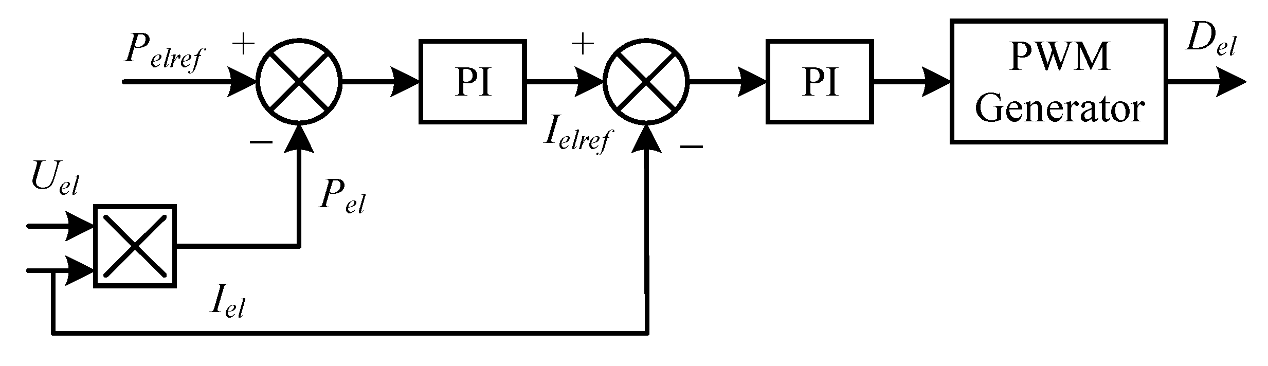
2.7. Hydrogen Production Electrolyzer Control Strategy

The electrolyzer control strategy in the isolated wind power hydrogen production system is shown in Figure 5.
The electrolyzer control strategy consists of a power outer loop and a current inner loop. In the DC–DC control system, the product of port voltage and current is the power. After passing through the PI controller of the power outer loop, the output is the current reference value, which differs from the current acquisition value and passes through the PI controller of the current inner loop. Finally, a signal wave is formed to the pulse width modulation generator. This strategy controls the current by controlling the power and is suitable as a power supply for variable power loads.

2.8. Storage Battery Control Strategy

The storage battery control strategy is shown in Figure 6.
The control strategy of the storage battery consists of a voltage outer loop and a current inner loop, which are similar to the electrolyzer control method. After the PI controller of the outer voltage loop, the output is the current reference value, which differs from the current acquisition value and passes through the PI controller of the inner current loop. Because the energy storage system involves charging and discharging, the voltage difference between the terminal voltage of the storage battery and the DC bus determines the direction of the current.
As can be seen from Figure 6, in the dual closed-loop voltage current control strategy, it is necessary to collect the system bus voltage in real time, compare the collected DC bus voltage (UDC) with the given value of DC bus voltage (UDC_ref), and then send the deviation generated by the comparison of the two through the voltage outer-loop PI regulator to obtain the reference value of the Li-ion battery current Iref. By comparing the actual current value (I) with the reference current (Iref) obtained through sampling, the deviation is calculated. This deviation is sent to the current inner-loop PI regulator. The resulting control signal is then sent to the pulse width modulation (PWM) pulse width modulator. By comparing the PWM carrier waveform with the modulating waveform, pulse width modulation signals for the upper and lower bridge arms are generated. These signals regulate the duty cycle of the half-bridge bi-directional DC/DC converter’s switching control transistors (T1 and T2). This process controls the charge and discharge of the energy storage system.

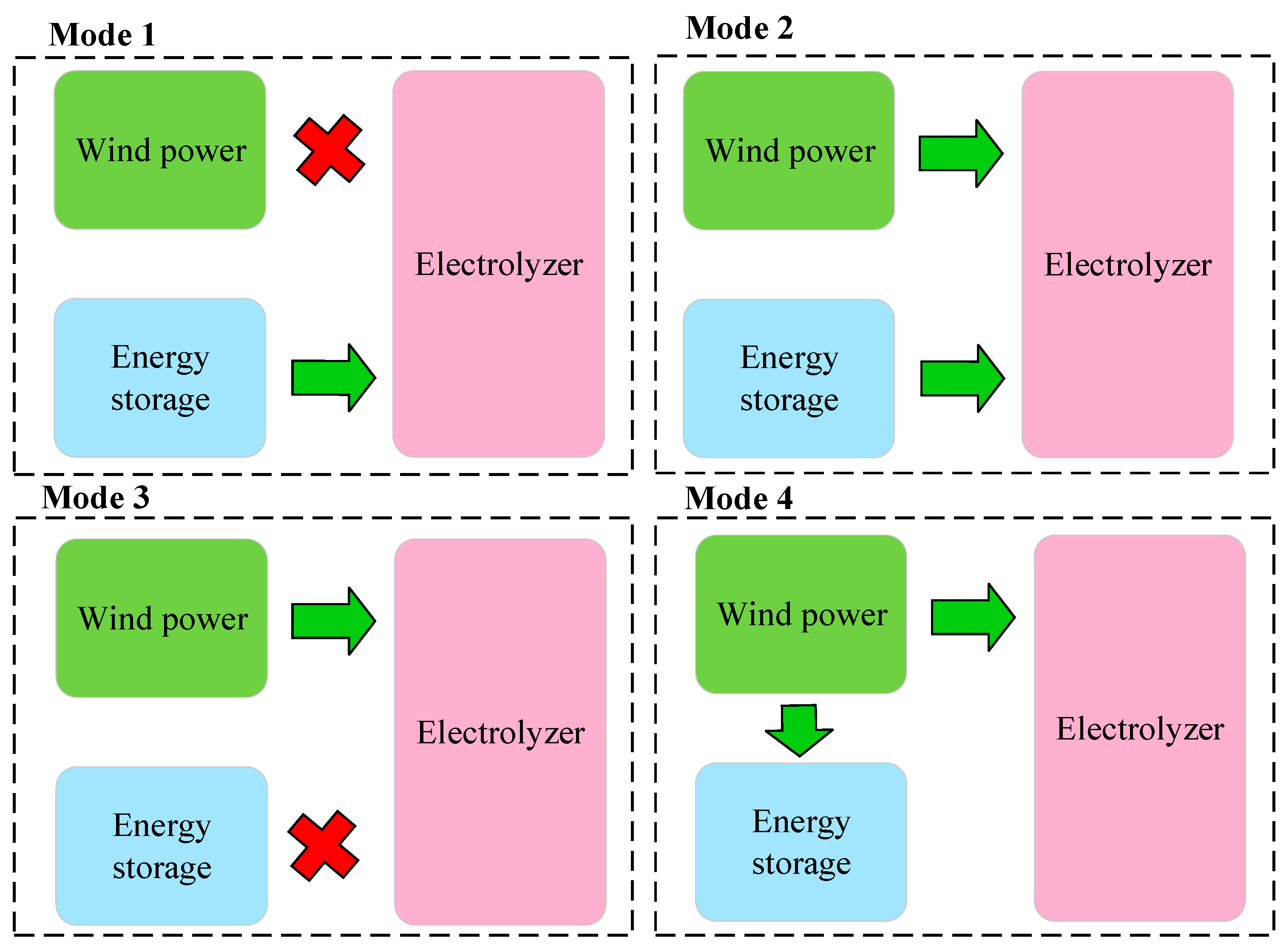
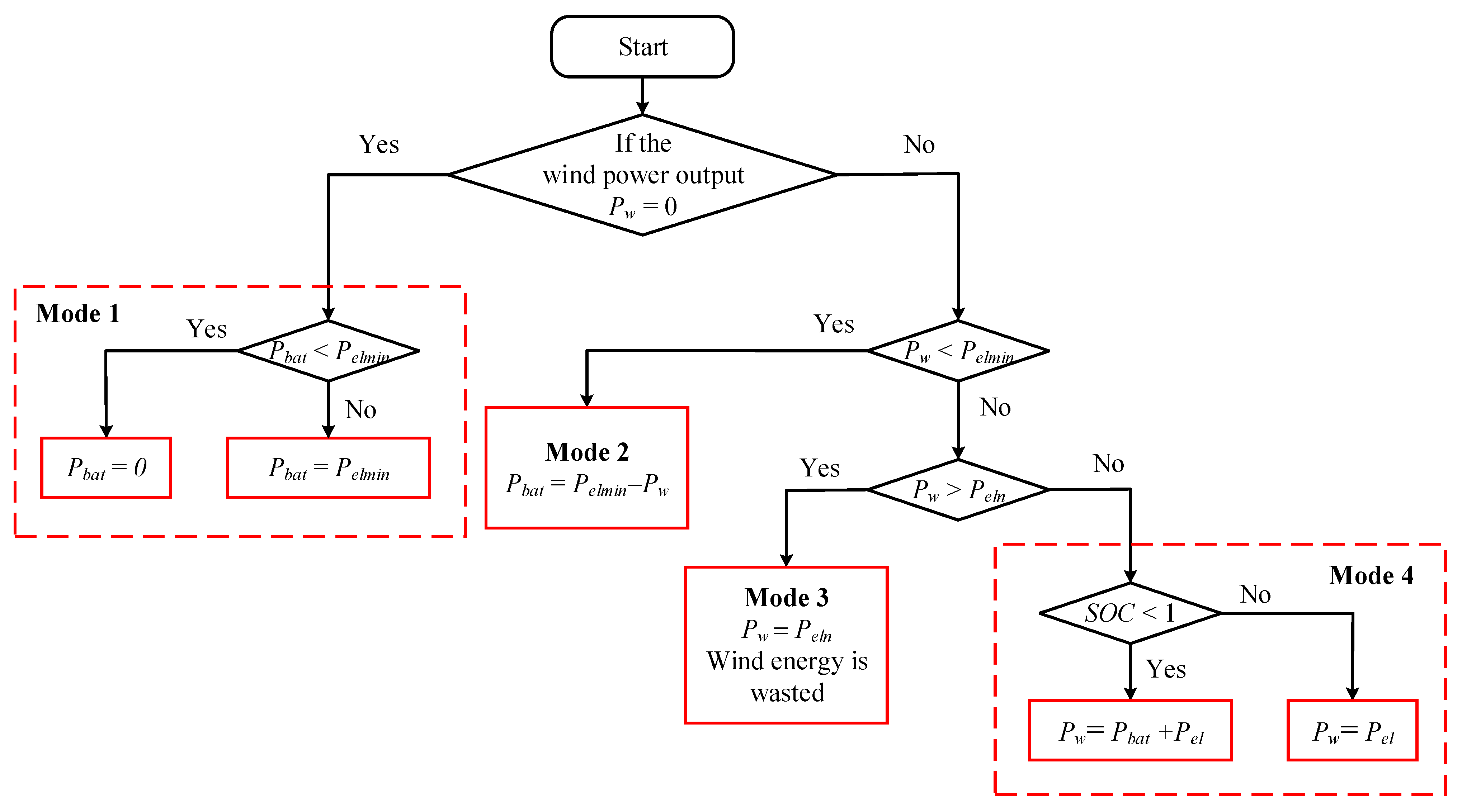
2.9. Overall Coordinated Control Strategy of Wind Power Hydrogen Production System

In order to realize the maximum wind energy utilization of the direct-drive permanent magnet synchronous wind turbine in the wind-coupled hydrogen production system, and to meet the functional needs of the hydrogen production load, it is necessary to regulate the balance of the system’s power.
The energy storage power output is
Pbat = PwPel
where Pbat is the battery output power; Pw is the wind turbine output power; and Pel is the hydrogen production load power.
According to the system, wind turbine output power Pw, hydrogen load power Pel, and the SOC of the battery in the energy storage unit, which is an independent operating mode of the wind power hydrogen generation system, are divided into four operating modes. The relationship between the system Pw in the Pel for the division of operating modes ensures the regulation of the power balance of the system, and the wind coupled to hydrogen production is divided into the following four modes.
Operation mode 1: When the fan output power is 0, the fan, due to maintenance or no wind, will enter the shutdown state. At this time, the minimum power of the electrolyzer from the battery will be provided once to ensure that the hydrogen electrolyzer maintains minimum power operation. At this time, Pbat = Pelmin. If the SOC of the storage battery is so low that it is not possible to keep the electrolyzer to maintain minimum power operation, the operation of the electrolyzer is stopped.
Operation mode 2: When the fan is in working condition and the output power of the fan is not sufficient to support the minimum output power of the electrolyzer, the battery will make up for the power gap together with the fan to meet the minimum output power of the hydrogen production electrolyzer to ensure stable operation of the system to maintain the power balance of the system. At this time, Pbat = PelminPw.
Operation mode 3: When the output power of the wind turbine is greater than the minimum operating power (Peln) of the hydrogen production electrolyzer but does not exceed the rated output power of the electrolyzer, the wind turbine can provide stable power for the electrolyzer alone. At this time, the SOC of the storage battery needs to be in a state where it can release energy at any time, i.e., the SOC needs to be maintained at more than 50%, which is used to prevent insufficient wind power in case of emergency. At this time, Pw = Peln.
Operation mode 4: When the wind power is full, the wind power output is greater than the rated power of the hydrogen generation electrolyzer. At this time, the wind power output can not only maintain the rated power of the hydrogen generation electrolyzer to work normally but also the wind power output exceeds the rated power of the hydrogen generation electrolyzer residual power, which allows for energy storage battery charging. In this mode, the storage battery is in a charging state to maintain the power balance of the system: Pw = Pbat + Pel. When the energy of the storage battery is saturated, the wind power output will be higher than the rated power of the hydrogen generator electrolyzer, and then there will be a certain amount of wind abandonment phenomenon to reduce the wind power output, and therefore there is a new power balance of the system: Pw = Pel.
The operation diagram of the coordinated control strategy is shown in Figure 7 below.

3. Simulation Verification

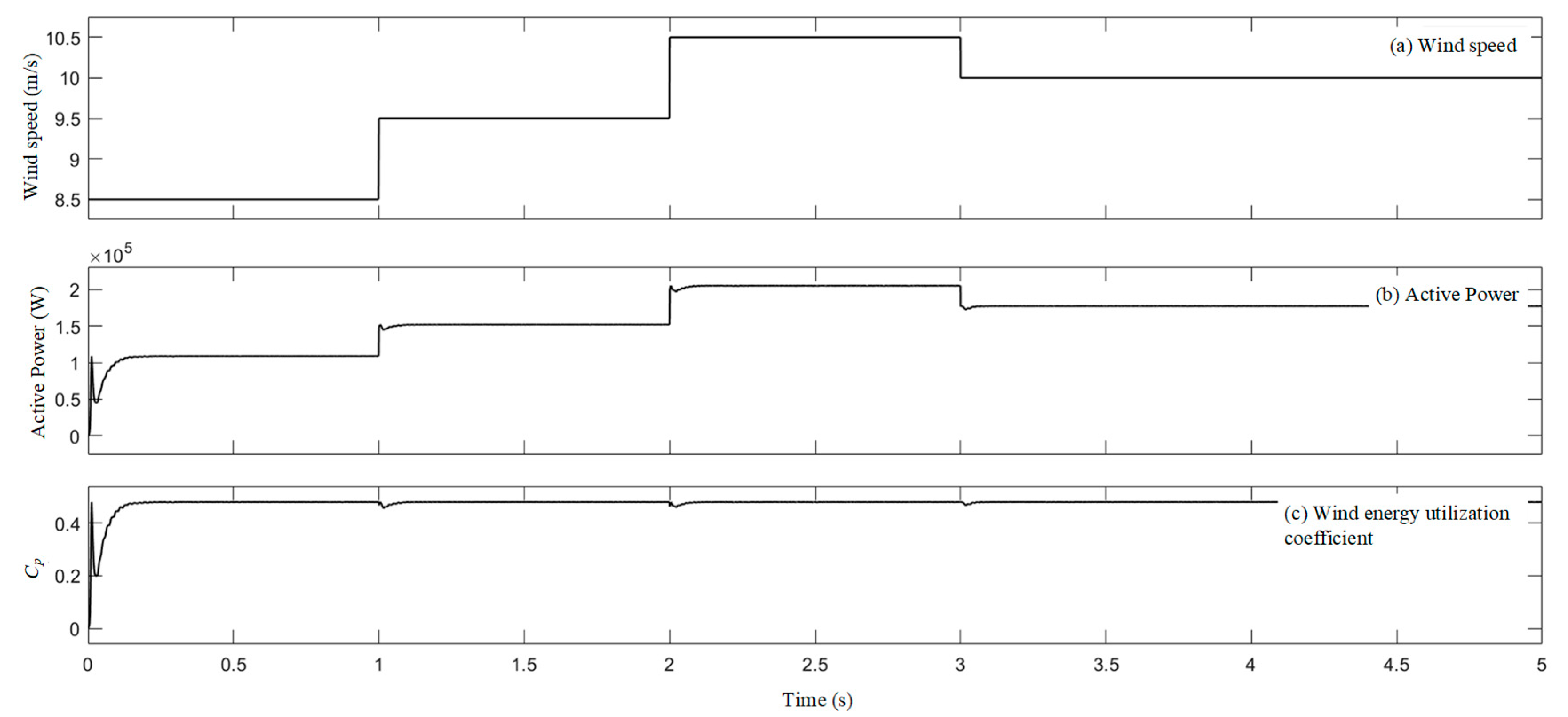
3.1. Wind Power MPPT Simulation Test

In order to verify the MPPT effect of the wind turbine, wind simulation equipment is used in this paper to generate seconds of wind data to verify the MPPT control model. The photo of the wind simulation device is shown in Figure 8, and the wind data are exported from the host computer after being processed by the microcontroller.
Based on the wind speed curve, the simulation results of the turbine’s output power are shown in Figure 9 using the reverse electromotive force load as the test load. We can see that the wind power shows a smooth rising trend in the initial stage after the system is started. When the wind speed rises at the first and second seconds, the wind turbine can quickly respond to the wind speed change and adjust to the maximum power output in a short time. When the wind speed decreases in the third second, the wind turbine can also quickly adjust to the maximum output. Therefore, the wind turbine has excellent MPPT performance, and it can effectively cope with the impact of wind speed fluctuations and ensure that the system operates in the best working condition.

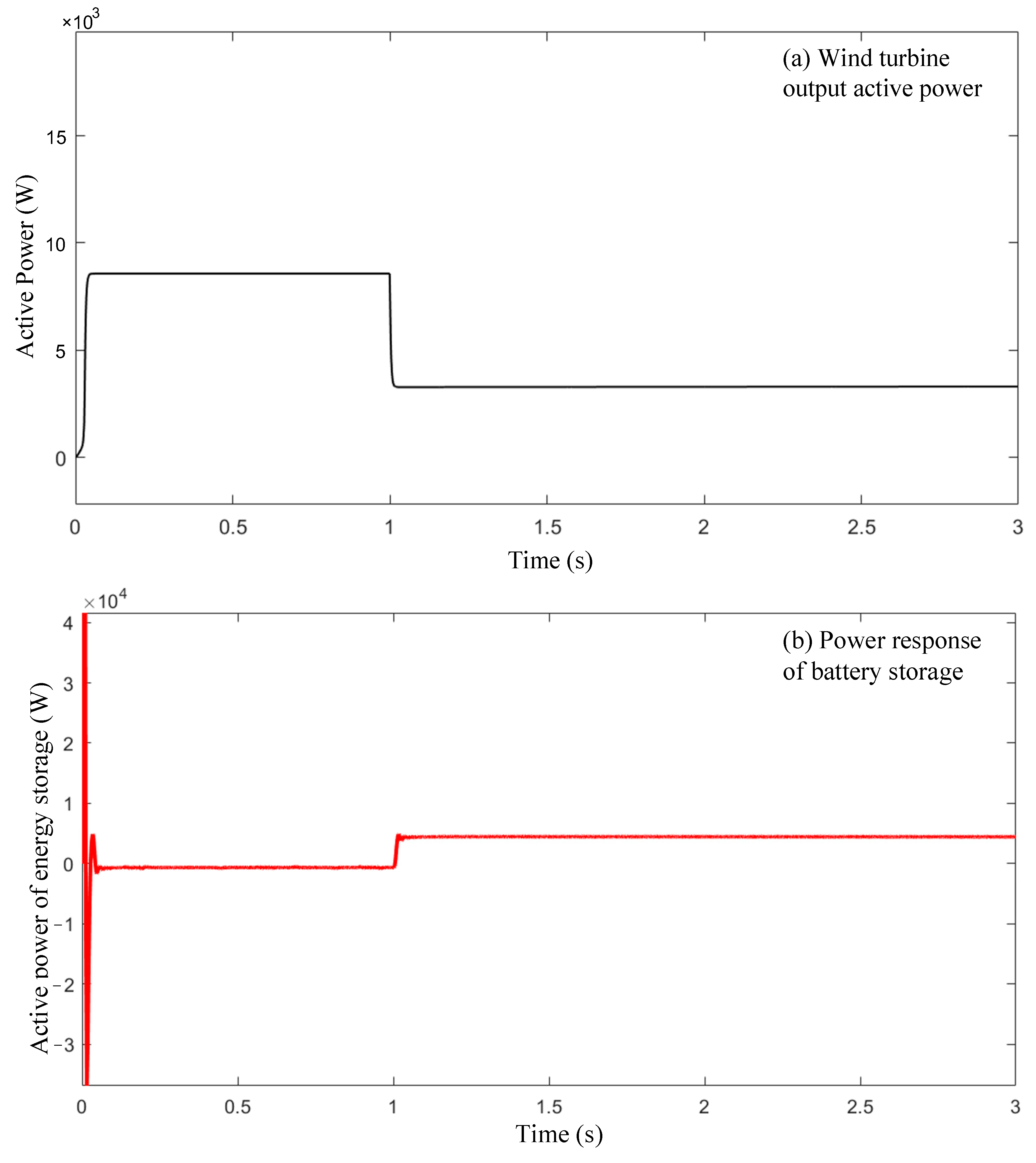
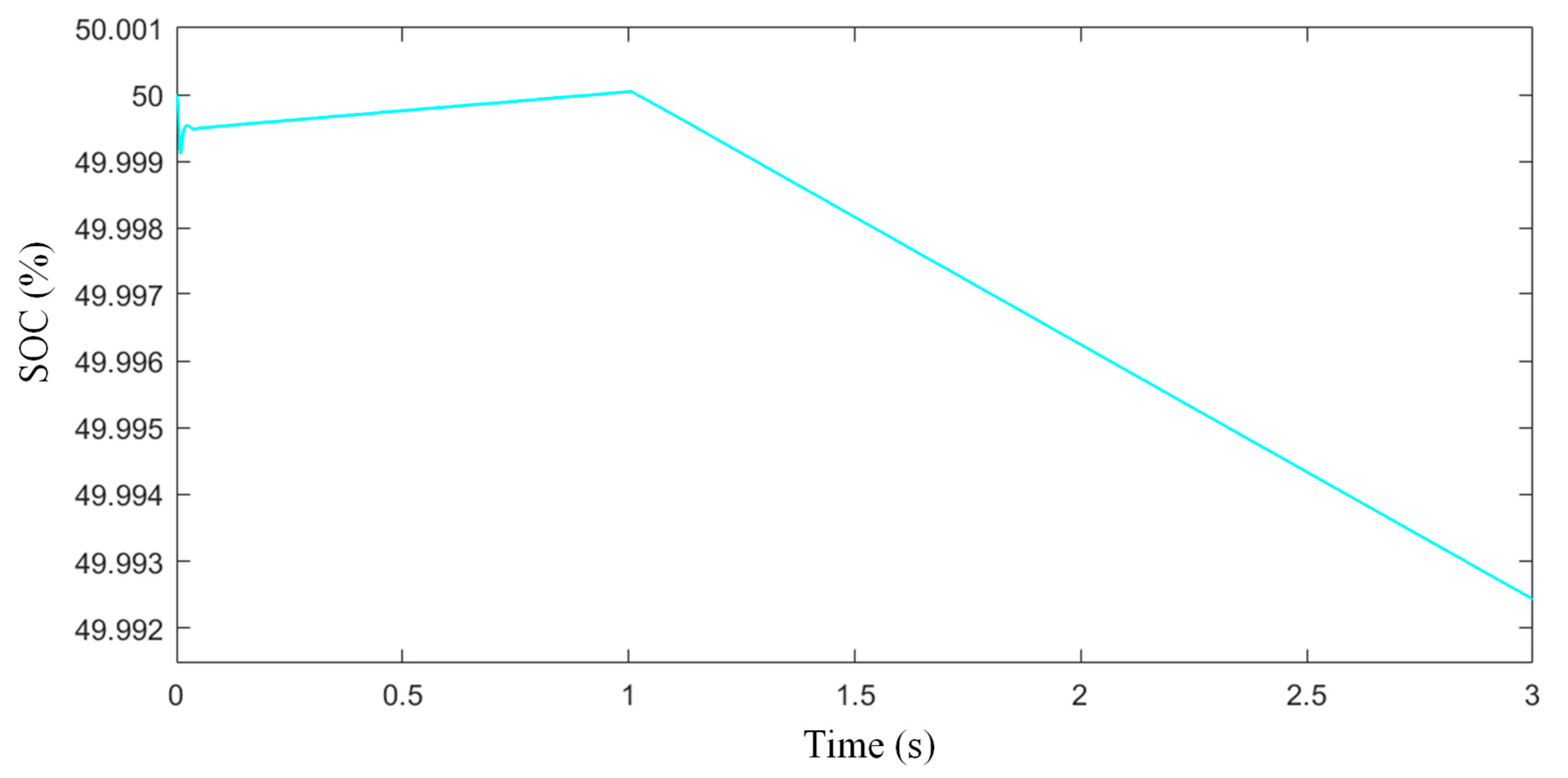
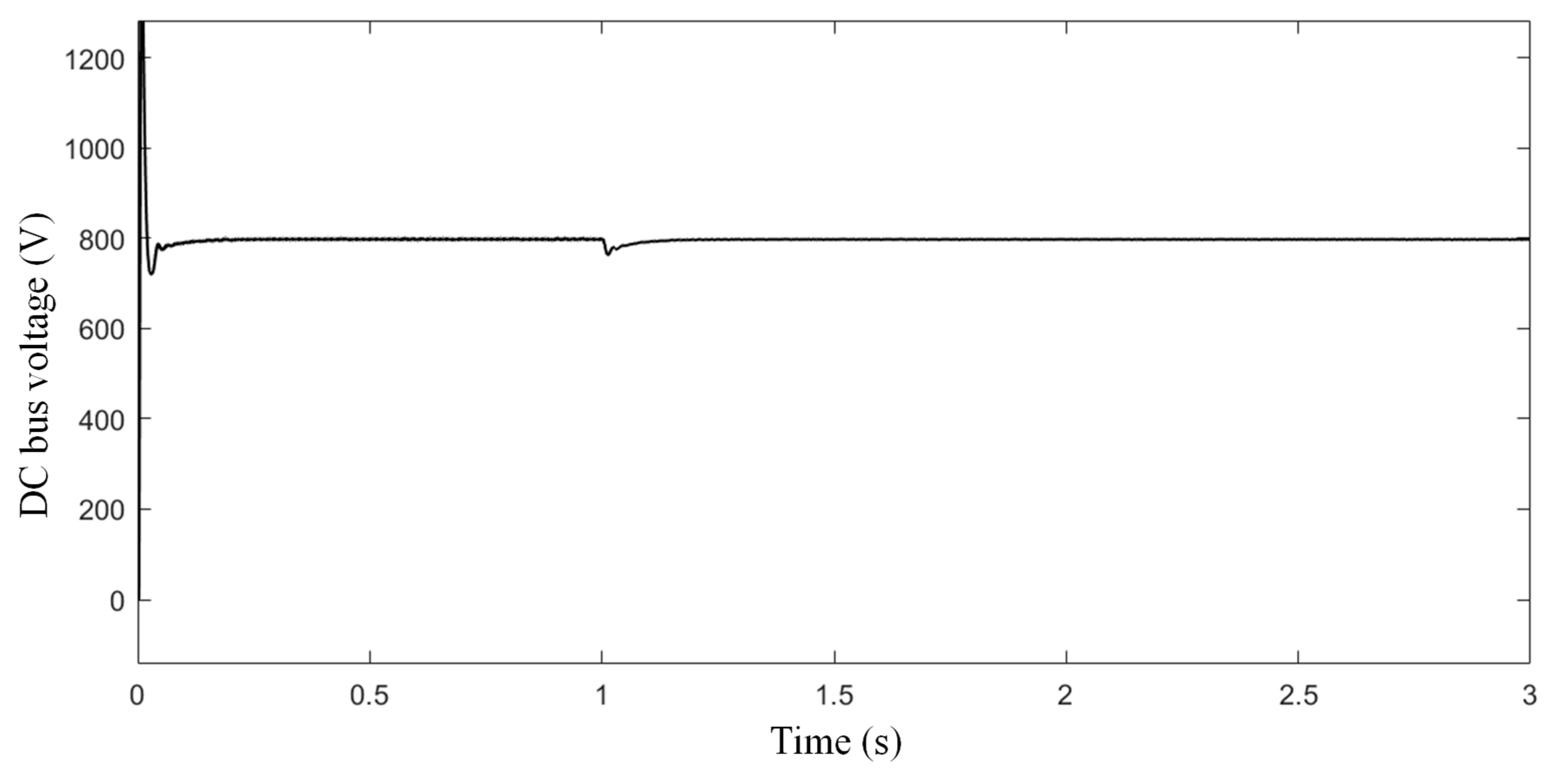
3.2. Simulation Test of Energy Storage System

Because the energy storage system itself exhibits capacitive characteristics, moments of high wind speed variation are suitable for testing the energy storage system. The wind speed is defined as 11 m/s at sampling 0, decreasing to 8 m/s after 1 s and maintaining this speed for the following 2 s. Based on the rapid change in wind turbine power, it is found at this point that the electrolyzer’s power remains constant, and the initial SOC of the storage battery is 50%. Figure 10, Figure 11 and Figure 12 show the power output of the energy storage unit, the change of the state of charge, and the operation of the DC bus voltage, respectively. It can be observed that when the power of the wind turbine in Figure 10a rises and then falls, the power of the energy storage unit changes accordingly. As shown in Figure 10b, it can reflect how the energy storage unit regulates the power in the fluctuation of the wind power system to ensure the stable operation of the system.
When the energy storage unit carries out charging and discharging operations, the charge state changes accordingly, as demonstrated in Figure 11, which shows the trend of the curve rising first and then falling. The fluctuation of the charge state reflects the dynamic adjustment of the energy storage unit in the charging and discharging process in the whole system to realize flexible energy interaction.
During the overall operation of the system, the DC bus voltage can be stabilized near the predetermined value by virtue of the control of the energy storage unit. Although the DC bus voltage fluctuates when the wind speed changes, the system can quickly recover and stabilize at the set value, and the variation curve of the DC bus voltage is shown in Figure 12. Through the simulation test of the energy storage system, the results show that the energy storage unit is able to maintain the stable operation of the system under the change of external environment.

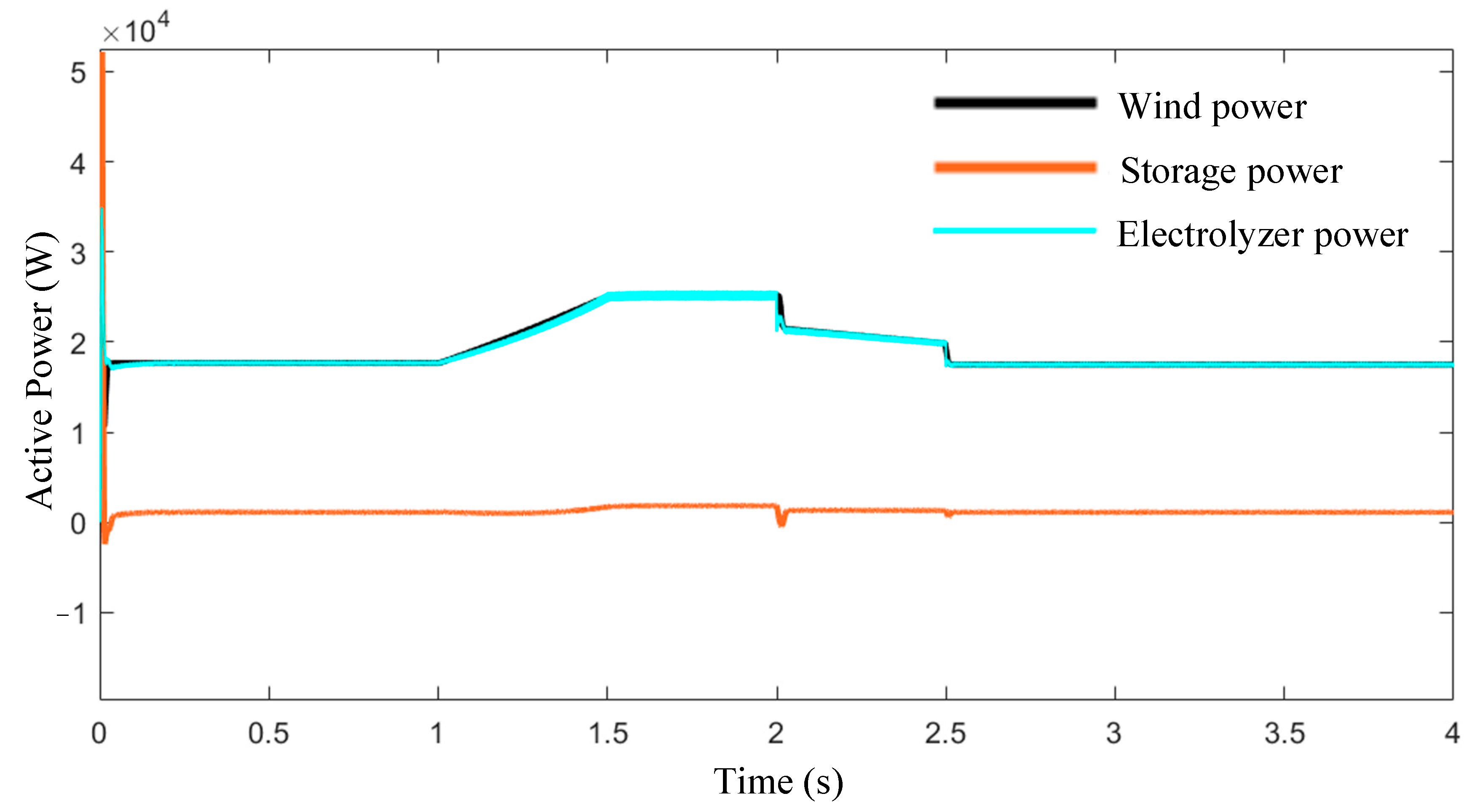
3.3. Simulation Test of Wind Power Hydrogen Production System Control Strategy

To assess the effectiveness of the control strategy for the wind power hydrogen production system, the complete model is developed and simulated using the MATLAB/Simulink platform in this study. The simulation duration for all four modes is set between 4 to 6 s, as this timespan allows components, such as wind turbines, to respond and stabilize swiftly. Wind data are simulated using wind modeling equipment, which includes stepwise and gradually varying wind speeds, as illustrated in Figure 13. For Mode 1, we set the wind speed to zero, representing a scenario where wind forces are insufficient to drive the wind turbine, effectively halting its operation.
Figure 14 depicts the power output simulation when the system operates in Mode 1. In this scenario, the wind turbine is unable to function due to either maintenance issues or inadequate wind speed. As a result, the energy storage unit solely provides the minimum required power for the electrolyzer to ensure that the hydrogen production process continues at its minimum power level.
Figure 15 illustrates the power simulation for operation Mode 2. In this mode, the wind turbine operates normally, but due to low wind speeds caused by weather conditions, the turbine’s output power is insufficient to meet the minimum required power for the electrolyzer. Consequently, the energy storage unit begins to assist in providing the necessary power to ensure that the electrolyzer operates at its minimum power. The figure demonstrates that as the wind speed fluctuates, the turbine’s output varies accordingly, and the energy storage unit adjusts its contribution to maintain the electrolyzer’s minimum power level.
Figure 16 presents the power simulation for operation Mode 3. In this mode, normal windy conditions are simulated with wind speeds falling within the typical range. The wind turbine’s output power is higher than the minimum required by the electrolyzer but lower than the electrolyzer’s rated power. At this point, the electrolyzer consumes the power generated by the turbine entirely for hydrogen production. As shown in the figure, the turbine’s output power gradually increases from 18 kW to 25 kW before reducing to 17 kW after 1.5 s. During this period, the electrolyzer fully utilizes the turbine’s output, with the power curve closely matching the turbine’s power output, while the energy storage unit remains idle, contributing no energy, and the power approaches zero.
Figure 17 depicts the power simulation for operation Mode 4. In this mode, the wind turbine operates in a high wind speed range, with its output exceeding the electrolyzer’s rated power. As a result, the energy storage unit begins to charge, absorbing the surplus wind energy. Once the energy storage unit nears its upper capacity (SOC = 98%), the turbine switches from MPPT mode to constant power control mode. The figure illustrates that the energy storage unit absorbs excess power until 4 s, at which point it reaches full capacity and ceases to charge. Subsequently, the energy storage unit’s power drops to zero, and the turbine shifts to a reduced power mode to meet the electrolyzer’s rated power demand.
This study constructs the overall model of the wind power hydrogen production system and conducts a simulation analysis of four distinct operation modes to evaluate the effectiveness of the system’s control strategy. Under varying wind speed conditions, the coordinated operation of the wind power system and the energy storage unit ensures that the electrolyzer consistently receives the required minimum power. The simulation results indicate that the system can dynamically adjust the operational states of both the wind turbine and the energy storage unit based on wind speed variations, optimizing energy utilization and storage and thus ensuring the stable performance of the wind power hydrogen production system.

4. Conclusions and Outlook

4.1. Conclusions

To address the issue of inadequate hydrogen production in the wind power hydrogen production system, this paper proposes a control strategy for the wind power coupled hydrogen production system based on power control. This strategy aims to maximize wind energy utilization while ensuring the stability of the bus voltage and the smoothness of the hydrogen production process. The key conclusions are as follows:
(1) A physical model for the wind power coupled hydrogen production system is proposed, which includes a wind turbine model, a PEM electrolyzer model, and an equivalent model for the energy storage equipment. The maximum power point tracking (MPPT) method, which combines the blade tip speed ratio method with the hill climbing method, is used to achieve stable maximum power capture by the wind turbine. A coordinated control strategy for both wind power and hydrogen storage systems is designed to ensure the system’s maximum utilization of wind energy.
(2) By studying the power-based control strategy for the wind power coupled hydrogen production system, four operating modes are proposed to ensure smooth operation of the electrolyzer between minimum and rated power levels. Stable hydrogen production is achieved while efficiently utilizing wind energy resources. Simulation results show that when sufficient wind energy is available, the electrolyzer can operate at full power and produce hydrogen efficiently while the energy storage device charges; when the wind speed is within the normal range, the electrolyzer can continuously and stably produce hydrogen according to the fluctuations in wind energy; and when the wind speed is insufficient, the energy storage device can effectively maintain the operation of the electrolyzer, ensuring the stability and reliability of the system. In conclusion, the proposed control strategy optimizes the performance of the wind power hydrogen production system, improving its operational efficiency and stability.

4.2. Outlook for Future Work

Future research can further explore robust control strategies for the system under more complex environmental disturbances, as well as equipment capacity configuration methods and cooperative optimization control strategies aimed at system design. In real-world operations, the wind energy storage hydrogen system often involves multiple operating modes, such as grid-connected operation, islanding operation, and peak-to-valley regulation. Switching between these modes may be influenced by energy fluctuations, load changes, and equipment responsiveness. Therefore, achieving smooth and efficient transitions between different operating modes is crucial for enhancing system flexibility and stability. Additionally, the rational allocation of equipment capacity is vital for meeting dynamic load demands and ensuring system economic efficiency, which can be further investigated from the perspectives of capacity redundancy control, dynamic regulation capability, and economic performance. The ultimate goal is to develop a more efficient, intelligent, and economical wind power to hydrogen integrated energy system, providing strong technical support for the deep utilization of renewable energy and the optimization of the energy structure.

Author Contributions

Conceptualization, Y.G.; methodology, Y.Q.; formal analysis, F.W.; investigation, W.W. and F.W.; writing—original draft, Y.Q. and Y.Y.; writing—review and editing, Y.Y. and Y.G.; visualization, W.W. and Y.Q.; funding acquisition, Y.G. and W.W. All authors have read and agreed to the published version of the manuscript.

Funding

This work is funded by the S&T Program of Hebei (23284502Z).

Data Availability Statement

The original contributions presented in this study are included in the article. Further inquiries can be directed to the corresponding author.

Conflicts of Interest

Author Weiwei Wang was employed by the Hebei Branch, China Nuclear Power Engineering Co., Ltd. The remaining authors declare that the research was conducted in the absence of any commercial or financial relationships that could be construed as potential conflicts of interest.

References

  1. Wang, W.; Qi, Y.; Zhang, X.; Xie, P.; Guo, Y.; Sun, H. Carbon Emission Optimization of the Integrated Energy Systemin Industrial Parks with Hydrogen Production from Complementary Wind and Solar Systems. Hydrogen 2025, 6, 8. [Google Scholar] [CrossRef]
  2. Nnabuife, S.G.; Hamzat, A.K.; Whidborne, J.; Kuang, B.; Jenkins, K.W. Integration of renewable energy sources in tandem with electrolysis: A technology review for green hydrogen production. Int. J. Hydrogen Energy 2024, 107, 218–240. [Google Scholar] [CrossRef]
  3. Anand, C.; Chandraja, B.; Nithiya, P.; Akshaya, M.; Tamizhdurai, P.; Shoba, G.; Subramani, A.; Kumaran, R.; Yadav, K.K.; Gacem, A.; et al. Green hydrogen for a sustainable future: A review of production methods, innovations, and applications. Int. J. Hydrogen Energy 2025, 111, 319–341. [Google Scholar] [CrossRef]
  4. Semadeni, M. Storage of energy. In Encyclopedia of Energy; Elsevier: Amsterdam, The Netherlands, 2004. [Google Scholar]
  5. Tashie-Lewis, B.C.; Nnabuife, S.G. Hydrogen production, distribution, storage and power conversion in a hydrogen economy—A technology review. Chem. Eng. J. Adv. 2021, 8, 100172. [Google Scholar] [CrossRef]
  6. Yang, F.; Wang, T.; Deng, X.; Dang, J.; Huang, Z.; Hu, S.; Li, Y.; Ouyang, M. Review on hydrogen safety issues: Incident statistics, hydrogen diffusion, and detonation process. Int. J. Hydrogen Energy 2021, 46, 31467–31488. [Google Scholar] [CrossRef]
  7. Asif, M.; Bibi, S.S.; Ahmed, S.; Irshad, M.; Hussain, M.S.; Zeb, H.; Khan, M.K.; Kim, J. Recent advances green hydrogen production, storage and commercial-scale use via catalytic ammonia cracking. Chem. Eng. J. 2023, 473, 145381. [Google Scholar] [CrossRef]
  8. Zhang, Q.; Qin, T.; Wu, J.; Hao, R.; Su, X.; Li, C. Synergistic Operation Strategy of Electric-Hydrogen Charging Station Alliance Based on Differentiated Characteristics. Energy 2024, 304, 132132. [Google Scholar] [CrossRef]
  9. Liu, J.; Xu, Z.; Wu, J.; Liu, K.; Guan, X. Optimal planning of distributed hydrogen-based multi-energy systems. Appl. Energy 2021, 281, 116107. [Google Scholar] [CrossRef]
  10. Zhang, H.; Yuan, T.J.; Tan, J.; Kai, S.J.; Zhou, Z. Hydrogen Energy System Planning Framework for Unified Energy System. Proc. CSEE 2022, 42, 83–93. [Google Scholar]
  11. Petkov, I.; Gabrielli, P. Power-to-hydrogen as seasonal energy storage: An uncertainty analysis for optimal design of low-carbon multi-energy systems. Appl. Energy 2020, 274, 115197. [Google Scholar] [CrossRef]
  12. Pan, G.; Gu, W.; Lu, Y.; Qiu, H.; Lu, S.; Yao, S. Optimal planning for electricity-hydrogen integrated energy system considering power to hydrogen and heat and seasonal storage. IEEE Trans. Sustain. Energy 2020, 11, 2662–2676. [Google Scholar] [CrossRef]
  13. Ren, Z.Y.; Luo, X.; Qin, H.L.; Jiang, Y.P.; Yang, Z.X.; Xu, Y. Mid/long-term Optimal Operation of Regional Integrated Energy Systems Considering Hydrogen Physical Characteristics. Power Syst. Technol. 2022, 46, 3324–3332. [Google Scholar]
  14. Li, Q.; Zhao, S.; Pu, Y.; Chen, W.; Yu, J. Capacity Optimization of Hybrid Energy Storage Microgrid Considering Electricity-Hydrogen Coupling. Trans. China Electrotech. Soc. 2021, 36, 486–495. [Google Scholar]
  15. Mendis, N.; Muttaqi, K.M.; Perera, S. Management of Battery-Supercapacitor Hybrid Energy Storage and Synchronous Condenser for Isolated Operation of PMSG Based Variable-Speed Wind Turbine Generating Systems. IEEE Trans. Smart Grid 2014, 5, 944–953. [Google Scholar] [CrossRef]
  16. Dash, V.; Bajpai, P. Power management control strategy for a stand-alone solar photovoltaic-fuel cell–battery hybrid system. Sustain. Energy Technol. Assess. 2015, 9, 68–80. [Google Scholar] [CrossRef]
  17. Li, J.; Li, G.; Ma, S.; Liang, Z.; Li, Y.; Zeng, W. Modeling and Simulation of Hydrogen Energy Storage System for Power-to-gas and Gas-to-power Systems. J. Mod. Power Syst. Clean Energy 2023, 11, 885–895. [Google Scholar] [CrossRef]
  18. Gil-García, I.C.; Fernández-Guillamón, A.; Molina-García, Á. Optimized Wind Power Plant Repowering and Green Hydrogen Production: Synergies Based on Renewable Hybrid Solutions. IEEE Access 2024, 12, 155607–155617. [Google Scholar] [CrossRef]
  19. Cai, G.; Chen, C.; Kong, L.; Peng, L. Control of Hybrid System of Wind/Hydrogen/Fuel Cell/Supercapacitor. Trans. China Electrotech. Soc. 2017, 32, 84–94. [Google Scholar]
  20. Deng, H.; Chen, J.; Teng, Y.X.; Zhang, B.; Fu, J. Energy management strategy of wind power coupled with hydrogen system. Acta Energiae Solaris Sin. 2021, 42, 256–263. [Google Scholar]
  21. Huang, D.; Qi, D.; Yu, N.; Cai, G. Capacity Allocation Method for Hydrogen Production System to Consuming Abandoned Wind Power. Acta Energiae Solaris Sin. 2017, 38, 1517–1525. [Google Scholar]
  22. Lu Je Yu, L.; Zheng, P.; Hou, S. Research on advance control strategy of wind hydrogen coupling system. Acta Energiae Solaris Sin. 2022, 43, 53–60. [Google Scholar]
  23. Xu, M.; Zhang, G.; Li, W.; Ge, L.; Song, Z.; Geng, Y.; Wang, J. Coordinated Control Strategy for Grid-Connected Integrated Energy System of Wind, Photovoltaic and Hydrogen. In Proceedings of the 2019 IEEE 8th International Conference on Advanced Power System Automation and Protection (APAP), Xi’an, China, 21–24 October 2019; pp. 1120–1124. [Google Scholar]
  24. Awasthi, A.; Scott, K.; Basu, S. Dynamic modeling and simulation of a proton exchange membrane electrolyzer for hydrogen production. Int. J. Hydrogen Energy 2011, 36, 14779–14786. [Google Scholar] [CrossRef]
  25. Görgün, H. Dynamic modelling of a proton exchange membrane (PEM) electrolyzer. Int. J. Hydrogen Energy 2006, 3, 29–38. [Google Scholar] [CrossRef]
  26. Raúl Sarrias-Mena Luis, M. Fernández-Ramírez, Carlos Andrés García-Vázquez, Francisco Jurado. Electrolyzer models for hydrogen production from wind energy systems. Int. J. Hydrogen Energy 2015, 40, 2927–2938. [Google Scholar] [CrossRef]
  27. Muljadi, E.; Butterfield, C.P. Pitch-controlled variable-speed wind turbine generation. IEEE Trans. Ind. Appl. 2001, 37, 240–246. [Google Scholar] [CrossRef]
  28. Du, C.; Du, X.; Fan, L.; Su, J. Two-variable Admittance Model for DFIG Stability Analysis Under the Entire Wind Speed Operation Range. Proc. CSEE 2022, 42, 5300–5312. [Google Scholar]
  29. Hu, S.; Guo, B.; Ding, S.; Yang, F.; Dang, J.; Liu, B.; Gu, J.; Ma, J.; Ouyang, M. A comprehensive review of alkaline water electrolysis mathematical modeling. Appl. Energy 2022, 327, 120099–120132. [Google Scholar] [CrossRef]
  30. Salameh, Z.M.; Casacca, M.A.; Lynch, W.A. A mathematical model for lead-acid batteries. IEEE Trans. Energy Convers. 1992, 7, 93–98. [Google Scholar] [CrossRef]
  31. Qi, J.; Li, W.; Zhu, M.; Li, Z. Impact of Low Voltage Ride-through Behavior of Direct-driven Wind Turbine on Voltage of Grid-connected Point and Optimal Control. Autom. Electr. Power Syst. 2023, 47, 105–113. [Google Scholar]
Figure 1. Schematic diagram of hydrogen production in this system.
Energies 18 02012 g001
Figure 2. Overall structure of wind power coupled hydrogen production system.
Energies 18 02012 g002
Figure 3. Schematic diagram of the equivalent circuit of the battery.
Energies 18 02012 g003
Figure 4. Improved optimization algorithm control strategy diagram.
Energies 18 02012 g004
Figure 5. Electrolyzer unit control strategy diagram.
Energies 18 02012 g005
Figure 6. Storage battery control strategy.
Energies 18 02012 g006
Figure 7. System operation mode power control flowchart.
Energies 18 02012 g007
Figure 8. Photos of wind simulation equipment.
Energies 18 02012 g008
Figure 9. Wind turbine output power simulation curve.
Energies 18 02012 g009
Figure 10. Power change curve of energy storage unit.
Energies 18 02012 g010
Figure 11. Charge state change curve of energy storage unit.
Energies 18 02012 g011
Figure 12. DC bus voltage variation curve.
Energies 18 02012 g012
Figure 13. Wind speed profiles for modes 2 to 4.
Energies 18 02012 g013
Figure 14. Run Mode 1 power simulation curve.
Energies 18 02012 g014
Figure 15. Run Mode 2 power simulation curve.
Energies 18 02012 g015
Figure 16. Run Mode 3 power simulation curve.
Energies 18 02012 g016
Figure 17. Run Mode 4 power simulation curve.
Energies 18 02012 g017
Table 1. Physical parameters and physical meanings of each physical parameter of the generalized equivalent circuit model for batteries.
Physical ParametersPhysical MeaningPhysical ParametersPhysical Meaning
E0No-load electromotive forceAVoltage amplitude fitting factor
KPolarization Voltage Fitting CoefficientBFitting factor for exponential capacity
QBattery capacity 0 t I b d t Discharge (positive values represent discharging; negative values represent charging)
IbBattery currentUbatBattery terminal voltage
Disclaimer/Publisher’s Note: The statements, opinions and data contained in all publications are solely those of the individual author(s) and contributor(s) and not of MDPI and/or the editor(s). MDPI and/or the editor(s) disclaim responsibility for any injury to people or property resulting from any ideas, methods, instructions or products referred to in the content.

