Article

Multi-Objective Optimization Research Based on NSGA-II and Experimental Study of Triplex-Tube Phase Change Thermal Energy Storage System

School of Environmental Science and Engineering, Tianjin University, Tianjin 300072, China
*
Author to whom correspondence should be addressed.
Energies 2025, 18(8), 2129; https://doi.org/10.3390/en18082129
Submission received: 26 March 2025 / Revised: 15 April 2025 / Accepted: 18 April 2025 / Published: 21 April 2025
(This article belongs to the Section J1: Heat and Mass Transfer)

Abstract

:
Energy storage technology is crucial for promoting the replacement of traditional energy with renewable energy and regulating the energy supply–demand relationship. This paper investigates a triplex-tube thermal energy unit storage to solve the intermediate heat storage and heat transfer problem of hot water supply and demand in clean heating systems. A multi-objective optimization method based on the elitist non-dominated sorting genetic algorithm (NSGA-II) was utilized to optimize the geometric dimensions (inner tube radius r 1 , casing tube radius r 2 , and outer tube radius r 3 ), focusing on heat transfer efficiency ( ε ), heat storage rate ( P t ), and mass (M). On this basis, the influence of the optimization variables was analyzed. The optimized configuration ( r 1 = 0.014 m, r 2 = 0.041 m, and r 3 = 0.052 m) was integrated into a modular design, achieving a 2.12% improvement in heat transfer efficiency and a 73.23% increase in heat storage rate. Experimental results revealed that higher heat transfer fluid (HTF) temperatures significantly reduce heat storage time, while HTF flow rate has a minimal impact. Increasing the heat release temperature extends the phase change material (PCM) heat release duration, with the flow rate showing negligible effects. The system’s thermal supply capacity is susceptible to heat release temperature.

1. Introduction

Renewable energy transition has become a key factor in national sustainable development and a focus of global attention [1], but the inherent volatility and instability of renewable energy significantly limits its advancement [2,3]. Energy storage technologies enable the conversion and storage of surplus electrical energy into thermal form, which can be subsequently released when energy generation mismatches demand, thereby reshaping the temporal dynamics of energy supply and demand [4,5]. Among these technologies, latent heat thermal energy storage using phase change materials (PCMs) has gained significant research attention due to its high energy storage density per unit mass, strong temperature stability during storage and release processes, and near-isothermal characteristics [6,7]. This technology demonstrates considerable potential for facilitating the integration of renewable energy sources. The phase-change heat exchanger is an important component of the integrated phase-change energy storage module. Among them, shell-and-tube configurations emerge as a predominant research focus owing to their optimal balance of thermal performance, structural simplicity, and economic viability [8]. Building upon this design, the triple-tube phase change heat exchanger incorporates an additional concentric tube to enhance the heat transfer surface area. This architectural evolution demonstrates significant improvements in thermal exchange efficiency while maintaining the inherent advantages of traditional shell-and-tube designs [9].
Optimizing the phase transition dynamics of phase change materials (PCMs), particularly their melting–solidification rates, is critical for enhancing the charge–discharge power density of latent heat storage systems [10], and advanced structural optimization methods can significantly reinforce this process. Recent numerical studies on helical coil-type heat exchangers have shown that geometric design can significantly enhance the PCM melting rate (by 16.5% within 5000 s) and energy storage capacity (by up to 18.8%) [11]. Huang et al. [12] addressed the issue of low thermal conductivity in phase change materials by designing a novel triplex-tube latent heat thermal energy storage system. Multi-parameter optimization using the response surface method and coupled dynamic temperature-flow field analysis revealed a 23.87% improvement in melting efficiency after optimization. The study quantified the critical roles of fin length, initial temperature, and tube wall temperature while confirming that the thermal conductivity of fins has no significant impact on the melting process. Reyes Rodríguez et al. [13] proposed a thermo-ecological optimization approach for shell-and-tube heat exchangers, integrating entransy dissipation theory with ecological evaluation. Using NSGA-II, they developed a multi-objective optimization framework that minimizes ecological impact and cost while addressing thermodynamic irreversibility in heat exchanger design. Srivastava and Sahoo [14] demonstrated that a pentagonal inner-tube configuration in triple-tube latent heat storage systems significantly enhances eutectic PCM melting efficiency, achieving 11.54% and 11.53% higher Stefan and Rayleigh numbers than triangular designs at Fo = 0.000254. It accelerated melting by 75–225% and boosted energy storage by 2.28–6.90% compared with triangular, square, and circular geometries, validating its industrial thermal management superiority. Mahdi et al. [15] numerically studied the system performance of a triple-tube heat exchanger with different fin geometric parameters under simultaneous storage and recovery or charging and discharging, and used the response surface methodology (RSM) to optimize it to find the optimal fin structure. Yao et al. [16] proposed a new V-shaped fin structure to enhance the performance of the triplex-tube phase change thermal storage unit. The effects of different V-shaped fin arrangements on thermal storage performance were studied through a two-dimensional model, and the optimal fin arrangement was determined. The results showed that the optimally arranged V-shaped fins can reduce the melting time of the phase change material by 31.92%. Bhim Kumar Choure et al. [17] optimized heat transfer in a triple-tube heat exchanger using triangular and curved fins with eccentric tube placement, achieving 63.87% faster melting and 175.16% higher heat transfer rates compared with conventional designs, demonstrating the effectiveness of strategic fin configuration. Zaytoun et al. [18] optimized a shell-and-tube latent heat storage system by replacing the single inner tube with a triple-tube line array. They found that a 0° orientation reduced cycle time by 44.4%, while a 90° orientation increased it by 15.83%, demonstrating the significant impact of tube arrangement on thermal performance. Hussain B et al. [19] optimized the outer annular area fin structure design to reduce the melting time of PCM in a triple-tube heat exchanger. Using the Taguchi optimization method, the optimal fin design configuration was determined by considering the branch fin design (F), angular position around the center tube ( α ), and branch angle ( β ) as independent factors. The optimal fin configuration reduced the melting time by 35% and improved energy storage characteristics compared with the reference baseline design. Yan, C. et al. [20] employed the enthalpy-porosity method to analyze natural convection and phase change processes, experimentally comparing the solidification behaviors of RT50 PCM in finless and arc-finned triplex-tube heat exchangers under rotational speeds (0.1–1.5 rpm). By optimizing fin parameters ( α , β , S) via an artificial neural network, they identified an optimal configuration ( α = 60 ° , β = 60 ° , S = 10 mm) that accelerated discharging speed by 80.33% compared with the finless system. In addition to V-shaped [16], other configurations such as Y-shaped [21], arched fins [22], elliptical fins [23], twisted fins [24], horsetail-stem-bionic-structured fins [10], and snowflake-pattern longitudinal fins [25] have also been systematically explored and employed to enhance thermal energy storage and release rates in PCM-based systems.
The influence of key parameters on the performance of triplex-tube heat exchangers, particularly heat transfer fluid (HTF) flow patterns, mass flow distribution, inlet temperature, and flow rate, has also been extensively investigated. These studies provide valuable insights into optimizing thermal performance and efficiency. Kun Yang et al. [26] investigated the dynamic effects of HTF flow patterns and mass flow distribution between inner and outer tubes on thermal storage performance. By incorporating pump power consumption into energy efficiency evaluation, their study revealed that increasing the outer tube’s mass flow ratio under turbulent conditions enhances energy efficiency while maintaining a constant total flow rate. Kun Yang et al. [27] also developed a two-dimensional mathematical model to analyze PCM melting in a triplex-tube heat exchanger (TTHX). Their results demonstrated that increasing the TTHX length enhances thermal energy storage capacity. Xiaoling Cao et al. [28] indicated that a triplex-tube heat exchanger with PCM demonstrates efficient heat storage and release characteristics, with higher HTF inlet temperatures and mass flow rates influencing thermal performance and stability. Sadiq et al. [29] investigated the thermal discharge performance of paraffin PCM in a triplex-tube heat storage system through combined experimental and numerical analysis. By employing Al2O3/CuO hybrid nano-additives to enhance thermal properties, they demonstrated that reducing the HTF inlet temperature or increasing its mass flow rate accelerates solidification, with temperature exhibiting a more pronounced influence than flow rate. Guangzeng Ma et al. [30] utilized 3D computational fluid dynamics (CFD) modeling to analyze a phase change heat storage/exchanger system, demonstrating that increasing HTF inlet temperature reduces outlet temperature rise time by 23%, while optimizing flow rate achieves 69% faster heating, with temperature dominating overflow rate in PCM thermal dynamics.
Current research primarily focuses on optimizing fin design, tube arrangement, fluid parameters, and nanoparticle utilization [31,32] to enhance melting performance and heat transfer efficiency [33]. However, the exploration of the influence of geometric shapes on thermal performance remains relatively limited. The short HTF flow path in the triplex-tube phase change unit limits sufficient heat exchange between HTF and PCM, resulting in poor heat release performance and restricted practical applications. While extensive theoretical work exists for triplex-tube units, studies on integrated modules remain scarce. To address this gap, this study (1) optimizes the key geometric dimensions of the triplex-tube phase change thermal energy storage unit based on multi-objective optimization theory to improve its overall performance and systematically analyzes the influence of optimization variables on individual objective functions. (2) Building upon the optimized structural dimensions, an integrated modular system for the triplex-tube phase change heat storage and exchange is developed. (3) A performance testing experimental platform is constructed to evaluate the heat storage and release characteristics of the phase change integrated module, assess its thermal response capability, and investigate the dynamic behavior of PCM during heat storage and release processes. The findings provide both a theoretical foundation and relevant references for the further integration of the device with practical applications.

2. Methodology

2.1. NSGA-II

Optimization techniques are a means of dealing with various practical optimization enhancement problems by using mathematical modeling as a tool. A complete mathematical model for multi-objective optimization should consist of decision variables, objective functions, and constraints. There is generally no global optimal solution that satisfies all objective functions as optimal values, but rather, a solution set that contains a certain number of compromised solutions needs to be solved. Pareto optimal represents an ideal state of resource allocation, and multiple Pareto optimal solutions constitute a Pareto optimal set, whose objective function values constitute a Pareto frontier. The key to solving a multi-objective optimization problem lies in determining a set of diverse Pareto optimal solutions that are both convergent and uniformly distributed along the Pareto front. Evolutionary algorithms developed based on the theory of Pareto optimality are well suited for solving complex multi-objective optimization problems. Among them, NSGA-II (non-dominated sorting genetic algorithm II) is a prominent algorithm that runs fast and has good convergence of the solution set compared with NSGA. It introduces a fast non-dominated sorting method to reduce the computational complexity, adopts an elite strategy to retain the dominant genes, and uses congestion distance and congestion distance comparison operators, which can optimize multiple conflicting objectives at the same time and ensure a more homogeneous distribution of Pareto optimal solutions, and facilitates the screening of compromise solutions, taking into account the different engineering needs.

2.2. Mathematical Model

2.2.1. Model Assumptions

To reasonably simplify the mathematical model of the triplex-tube phase change thermal storage unit, the following assumptions are made:
1.
The HTF flow is treated as one-dimensional along the flow direction with axisymmetric heat transfer, allowing the heat transfer model to be approximated as two-dimensional.
2.
The phase change thermal storage process refers exclusively to latent heat storage, excluding sensible heat effects.
3.
The external insulation layer effectively isolates heat transfer, rendering heat loss between the unit and environment negligible. The outer tube surface is treated as adiabatic.
4.
Except for density, material properties are temperature independent, with natural convection driven solely by density variations, satisfying the Boussinesq approximation.
5.
The HTF is incompressible, with constant thermophysical properties and fixed inlet/outlet temperatures.
6.
The thermal resistance of the heat exchange surfaces in the thermal energy storage unit is negligible.

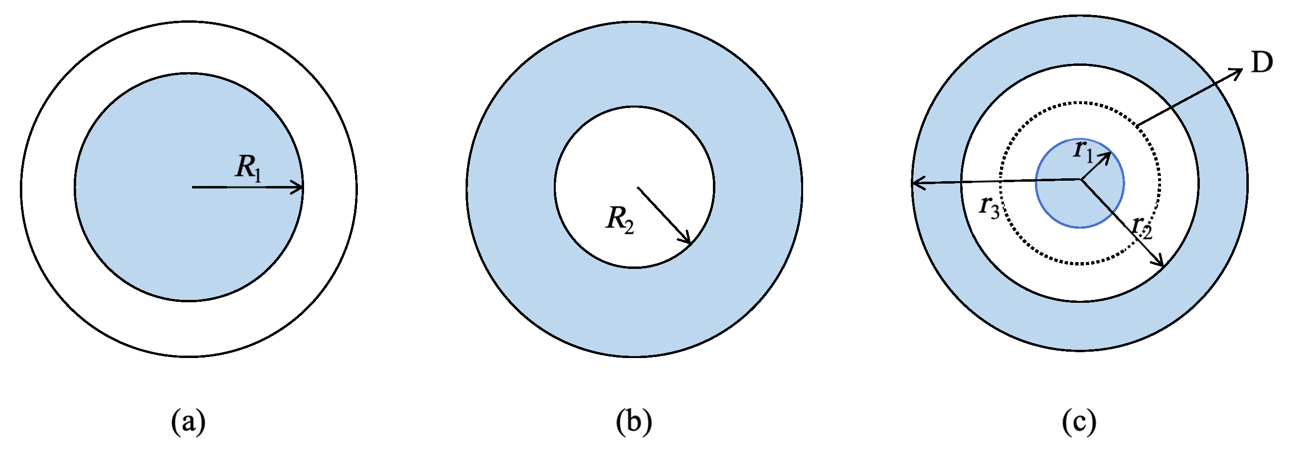
2.2.2. Optimization Variables

In the optimization of phase change heat exchangers, geometric dimensions critically influence heat transfer efficiency, storage duration, and mass. The main structural dimensions of the triplex-tube thermal energy storage unit include the inner tube diameter, the middle tube diameter, the outer tube diameter, the wall thickness, and the tube length. As tube radius and length are primary factors affecting triplex-tube unit performance [33], the inner tube radius ( r 1 ), casing tube radius ( r 2 ), and outer tube radius ( r 3 ) are selected as optimization variables, while maintaining a constant wall thickness ( δ ) sufficient for pressure resistance. The optimization premise is to enhance the comprehensive performance of the heat storage unit while maintaining its heat storage capacity unchanged. Under the condition of constant heat storage capacity, the tube length L can be uniquely determined by the inner tube radius and the casing tube radius.

2.2.3. Objective Function

Heat transfer efficiency, serving as the primary optimization objective, directly reflects the energy utilization effectiveness of thermal storage units. Time cost and unit mass are critical optimization parameters to prevent excessively long heat storage processes and cumbersome designs.
Equation (1) calculates heat transfer efficiency ε , where S is the latent heat storage capacity of the triplex-tube phase change thermal energy storage unit, Q denotes heat input to the system, and W represents pump power consumption for overcoming resistance losses in the thermal storage unit.
ε = E o u t E i n = S Q + W
Since the outer tube surface is an adiabatic boundary, the system’s thermal input (Q) should equal the total heat dissipation from the heat transfer fluid (HTF) in both the inner tube and the outer tube [34], as expressed by the following equation:
Q = Q 1 + Q 2 = c p t ( m s 1 Δ T 1 + m s 2 Δ T 2 )
where m s 1 and m s 2 are the mass flow rates of the inner tube and outer tube, and Δ T 1 and Δ T 2 indicate the temperature differences between the inlet and outlet of the HTF flowing through the inner and outer tubes.
As shown in Figure 1, the blue-colored sections represent the heat transfer fluid, while the white sections denote the PCM. The heat storage time (t) of the shell-and-tube heat exchanger can be calculated using the following expression in [35].
Model 1:
t 1 = H ρ b h d 2 2 λ ( T i n T p ) 1 + R 1 h d 2 ln 1 + h d R 1 1 2 + R 1 h d
Model 2:
t 2 = H ρ b h d 2 2 λ ( T i n T p ) 1 R 2 h d 2 ln 1 h d R 2 1 2 R 2 h d
where t 1 and t 2 represent the completion time of latent heat storage for heat transfer model 1 and model 2, and R 1 and R 2 are the radii of the inner tube and outer tube when acting as heat exchange fluid channels.
Assume the existence of a phase change interface D that divides the PCM layer into an inner region and an outer region (Figure 1c). The inner region of the PCM and the inner tube can be regarded as a heat transfer model 1, where the inner tube contains the HTF and the outer tube is made of the PCM. Meanwhile, the outer region of the PCM and the outer tube can be considered as a heat transfer model 2, in which the inner tube is composed of the PCM and the outer tube contains the HTF. Assuming that the heat storage processes of the two layers of phase change materials do not affect each other, the position of the phase change interface D ( h d ) can be determined by the following Equation (5):
H ρ b h d 2 2 λ ( T i n T p ) 1 + r 1 h d 2 ln 1 + h d r 1 1 2 + r 1 h d = H ρ b ( r 2 r 1 h d ) 2 2 λ ( T i n T p ) 1 r 2 r 2 r 1 h d 2 ln 1 r 2 r 1 h d r 2 1 2 r 2 r 2 r 1 h d
Solving gives h d , which is the thickness of the inner layer phase change material. Therefore, the completion time t of the latent heat storage process of the triplex-tube phase change thermal energy storage unit should be
t = H ρ b h d 2 2 λ ( T i n T p ) 1 + r 1 h d 2 ln 1 + h d r 1 1 2 + r 1 h d
For the temperature differences Δ T 1 , Δ T 2 between the inlet and outlet of the HTF, they can be determined by the following method [34].
Length L can be determined by the following Equation (7):
L = S H ρ b π ( r 2 2 ( r 1 + δ 2 ) )
The heat storage unit with a length of L is discretized into n–length units with a length of Δ x . Assuming that all the energy lost by the HTF is used for the heat storage of the PCM, then the energy conservation Equations (8) and (9) can be listed for each length unit dx.
π ( ( r 1 + h d ) 2 r 1 2 ) ρ b H d x = c p m s 1 t 1 ( x ) d Δ T
π ( r 2 2 ( r 1 + h d ) 2 ) ρ b H d x = c p m s 2 t 2 ( x ) d Δ T
where
t ( x ) = H ρ b h d 2 2 λ ( T i n T p ) C F
C F = 1 + r 1 h d 2 ln 1 + h d r 1 1 2 + r 1 h d
Taking the temperature difference between the inlet and outlet of the HTF in the inner tube as an example, by transforming Equation (8),
d Δ T p 1 ( x ) Δ T p 1 ( x ) = A d x
A = 2 λ π ( ( r 1 + h d ) 2 r 1 2 ) m s 1 h d 2 C F c p
where Δ T p 1 is the temperature difference between the HTF and the PCM in the inner tube. Equation (12) is integrated with respect to x.
Δ T p 1 ( x ) = ( T i n T p ) e A x
For a heat storage unit with a length of L, x = L . Substituting it into Equation (13), the temperature difference between the outlet of the HTF flowing through the inner tube and the PCM is
Δ T p 1 = ( T i n T p ) e A L
Then the temperature difference between the inlet and outlet of the HTF flowing through the inner tube is
Δ T 1 = T i n T p Δ T p 1
Similarly, the temperature difference between the inlet and outlet of the HTF flowing through the outer tube is
Δ T 2 = T i n T p Δ T p 2
Within the heat storage time t, the power consumption of the water pump used to overcome the resistance loss of the heat exchange unit [26] should be
W = W 1 + W 2
W 1 = π r 1 2 u 1 Δ p 1 t
W 2 = π ( r 3 2 r 2 2 ) u 2 Δ p 2 t
where W 1 and W 2 represent the power consumption of the pump that drives the HTF in the inner tube and outer tube within time t, respectively. Δ p 1 , Δ p 2 are the pressure losses of the HTF flowing through the inner and outer tubes, which can be obtained by the following formula [36]:
Δ p = ξ L d h ρ h u 2 2
For the inner tube, the friction factor ξ of the HTF along the flow path can be obtained by the following formula: When the flow is laminar ( R e 2100 ) [37],
ξ = 64 R e
When the flow is turbulent ( R e > 2100 ) [38],
ξ = 0.3164 R e 0.25
For the outer tube, the friction factor ξ of the HTF along the flow path can be obtained by the following formula. When the flow is laminar ( R e 2100 ) [39,40],
ξ = 64 ϕ R e
ϕ = 1 + r 2 r 3 2 ln r 2 r 3 + 1 r 2 r 3 2 1 r 2 r 3 2 ln r 2 r 3
When the flow is turbulent ( R e > 2100 ) [41],
ξ = 1.8 log 10 ( ϕ R e ) 1.5 2
d h = 4 π ( r 3 2 r 2 2 ) 2 π ( r 3 + r 2 ) = 2 ( r 3 r 2 )
As the amount of PCM increases, the time required to complete thermal storage also extends. Therefore, thermal storage time alone as an evaluation metric is insufficient. To address this, heat storage rate P t is calculated using Equation (28) [42], defined as the ratio of the latent heat storage capacity (S) to the charging time (t). This parameter represents the heat storage capacity per unit time of the phase change thermal storage unit upon completion of the latent heat storage process.
P t = S t
The total mass of the triplex-tube thermal energy storage unit is the sum of the mass of the metal casing and the mass of PCM, as expressed by Equation (29), where ρ M represents the density of the tube material, L denotes the unit length, and H is the latent heat of the phase change material.
M = π ( r 1 + δ ) 2 r 1 2 + ( r 2 + δ ) 2 r 2 2 + ( r 3 + δ ) 2 r 3 2 L ρ M + S H

2.2.4. Constraints

The optimization variables r 1 , r 2 , and r 3 are subject to the following constraints:
1.
The variables must satisfy r 1 < r 2 < r 3 .
2.
The latent heat storage completion time (t) of the triplex-tube phase change thermal storage unit must be less than the user-specified time ( τ ).
3.
The unit length (L) cannot exceed the user-defined maximum length (l) due to spatial and practical application limitations.

2.3. Numerical Methods

The multi-objective optimization algorithm NSGA-II is implemented using MATLAB R2018a. Considering Pareto solution convergence and computation time, the population size is set to 140 with 600 iterations. An optimization coefficient of 0.5 is selected to observe the Pareto solution distribution better. Combined with the application conditions, the phase change temperature T p is determined to be 50 °C, the design condition is T i n = 65 °C, and m s 1 = m s 2 = 0.5 kg/s. The mathematical form of the multi-objective optimization problem is as follows:
M a x i m i z e f 1 ( r ) = ε ( r 1 , r 2 , r 3 ) M a x i m i z e f 2 ( r ) = P t ( r 1 , r 2 , r 3 ) M i n i m i z e f 3 ( r ) = M ( r 1 , r 2 , r 3 ) r 1 < r 2 < r 3 , s . t . t ( r 1 , r 2 , r 3 ) 6000 s , L ( r 1 , r 2 , r 3 ) 1.4 m , 8 m m r 1 15 m m , 37 m m r 2 45 m m , 46 m m r 3 55 m m .
The selection of specific values is shown in Table 1.
To select a solution that combines theoretical optimality and engineering feasibility from the Pareto front for subsequent research, the weighted-sum method is employed for decision making. Multiple objectives are normalized, with different weight coefficients assigned to each objective function based on decision-maker preferences. The specific determination method is provided as follows. Considering both the multi-objective optimization results and practical system requirements, the weight coefficients were selected as λ 1 = 0.35 , λ 2 = 0.45 , and λ 3 = 0.2 .
F ( x ) = i = 1 q λ i f i ( x ) f i ( x ) min f i ( x ) max f i ( x ) min i = 1 q λ i = 1 λ i [ 0 , 1 ]

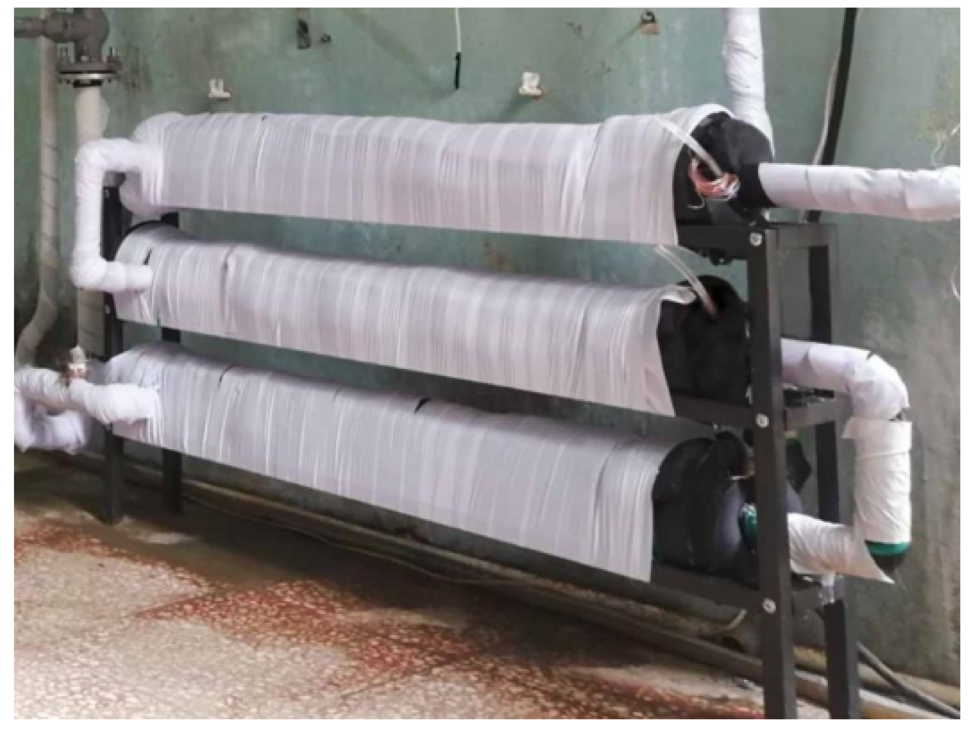
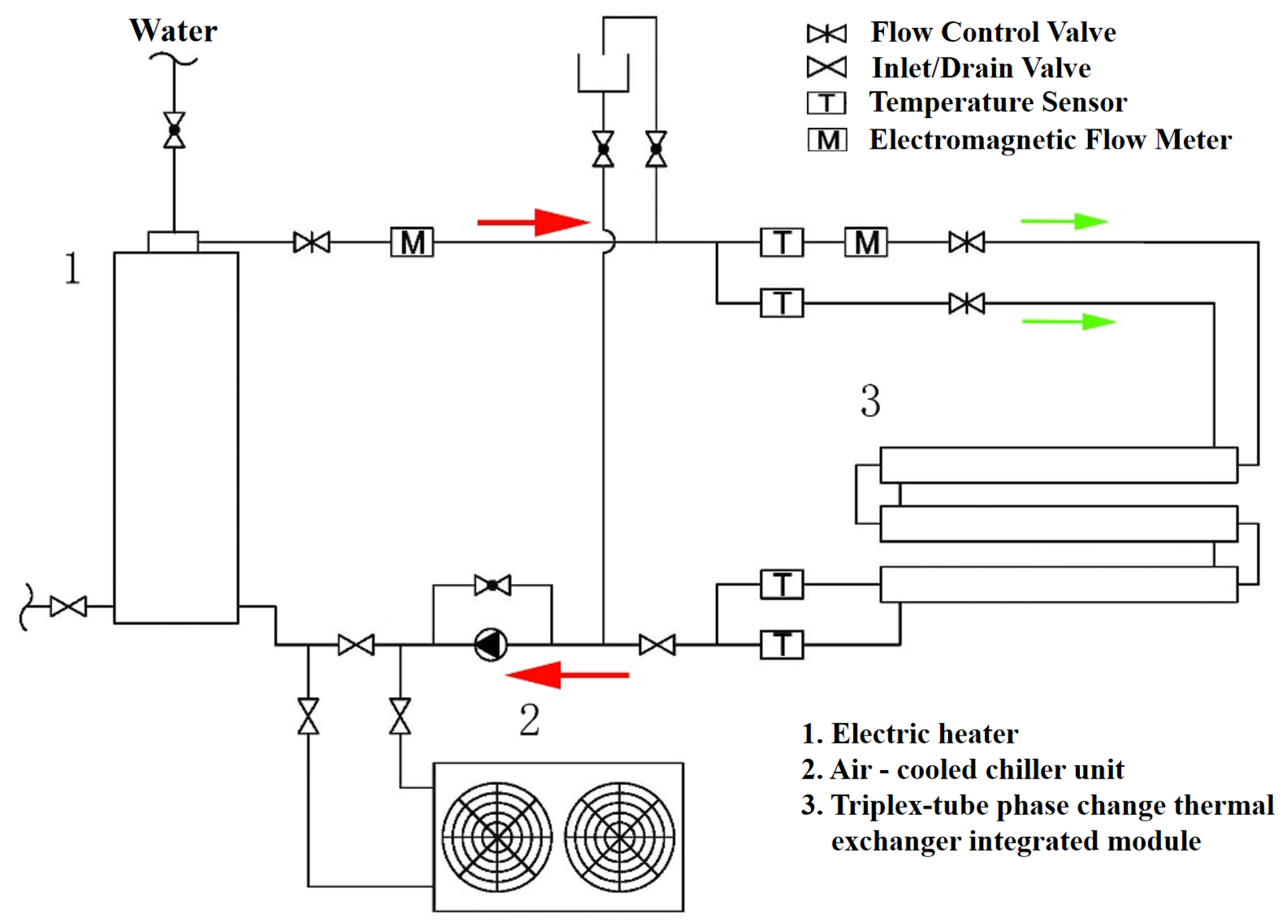
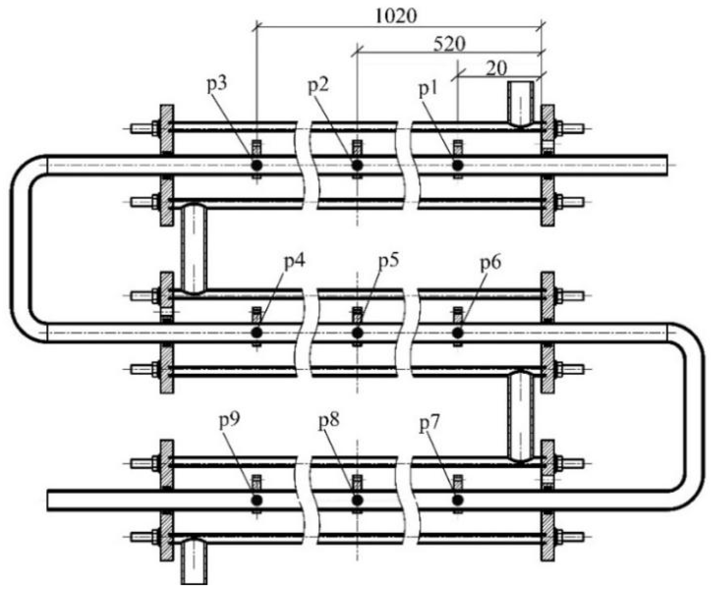
2.4. Experimental Design

Based on the optimized dimensions of the triplex-tube unit, three units were connected in series to form an integrated triplex-tube thermal energy storage module, as shown in Figure 2. A performance-testing experimental platform for the integrated module was constructed.
Considering the phase change temperature, physicochemical properties and economic performance, OPE50E from Rubitherm Technologies GmbH was selected as the PCM for this experiment.
The experimental system comprised five primary components: a heating unit, a cooling unit, a thermal storage unit, a power circulation unit, and auxiliary equipment. The system utilized an electric water heater as the heating device for the HTF, generating constant-temperature hot water for the heat storage process. A chiller and the electric water heater were connected in series to produce constant-temperature cold water below the PCM solidification temperature for the heat release process. The thermal storage unit featured a horizontally oriented triplex-tube phase change thermal storage integrated module. The power circulation system utilized a variable-frequency constant-pressure pump. Auxiliary equipment included a piping system and a temperature measurement system. A schematic diagram is shown in Figure 3. The integrated triplex-tube module was assembled by serially connecting the inner tubes via gas welding and the outer tubes using PVC thermal fusion. Each unit’s PCM-filled space remains independent. Water served as the HTF, circulating through the inner and outer tubes to exchange heat with the PCM. The information of the main instruments and equipment is shown in Table 2.
Temperature measurements within the PCM were conducted using K-type thermocouples, MX-100 Standard software (MX180) on a PC, and a data acquisition system. As shown in Figure 4, three measurement points were arranged along the axial direction in the PCM-filled layer of each unit, positioned 20 mm, 520 mm, and 1020 mm from the right end cover.
The main service object of this phase change heat exchanger is the low-temperature radiant floor heating system. Heat users are often concerned about the heating temperature of the system. Therefore, the experiment mainly focuses on the influence of different operating conditions. It looks at the influence on the heat storage and release process, as well as the heating water temperature. This can provide certain experiences and references and help with the application of the triple-tube phase change heat storage heat exchanger in real-life scenarios. The experimental scheme in Table 3 was implemented. Initial ambient temperatures were maintained at 27 °C during heat storage and 50 °C during heat release phases to establish controlled boundary conditions.

3. Results

3.1. Validation of Numerical Model

To validate the numerical model in this study, the theoretical phase change completion time is compared with the experimental results. The system parameters are set as follows: S = 700 kJ, r 1 = 0.010 m, r 2 = 0.040 m, r 3 = 0.051 m, and the mass flow rate in the tube is 0.56 kg/s. According to Table 4, the close agreement between theoretical and experimental phase transition times, with an error of less than 5%, confirms the reliability of the analytical model.

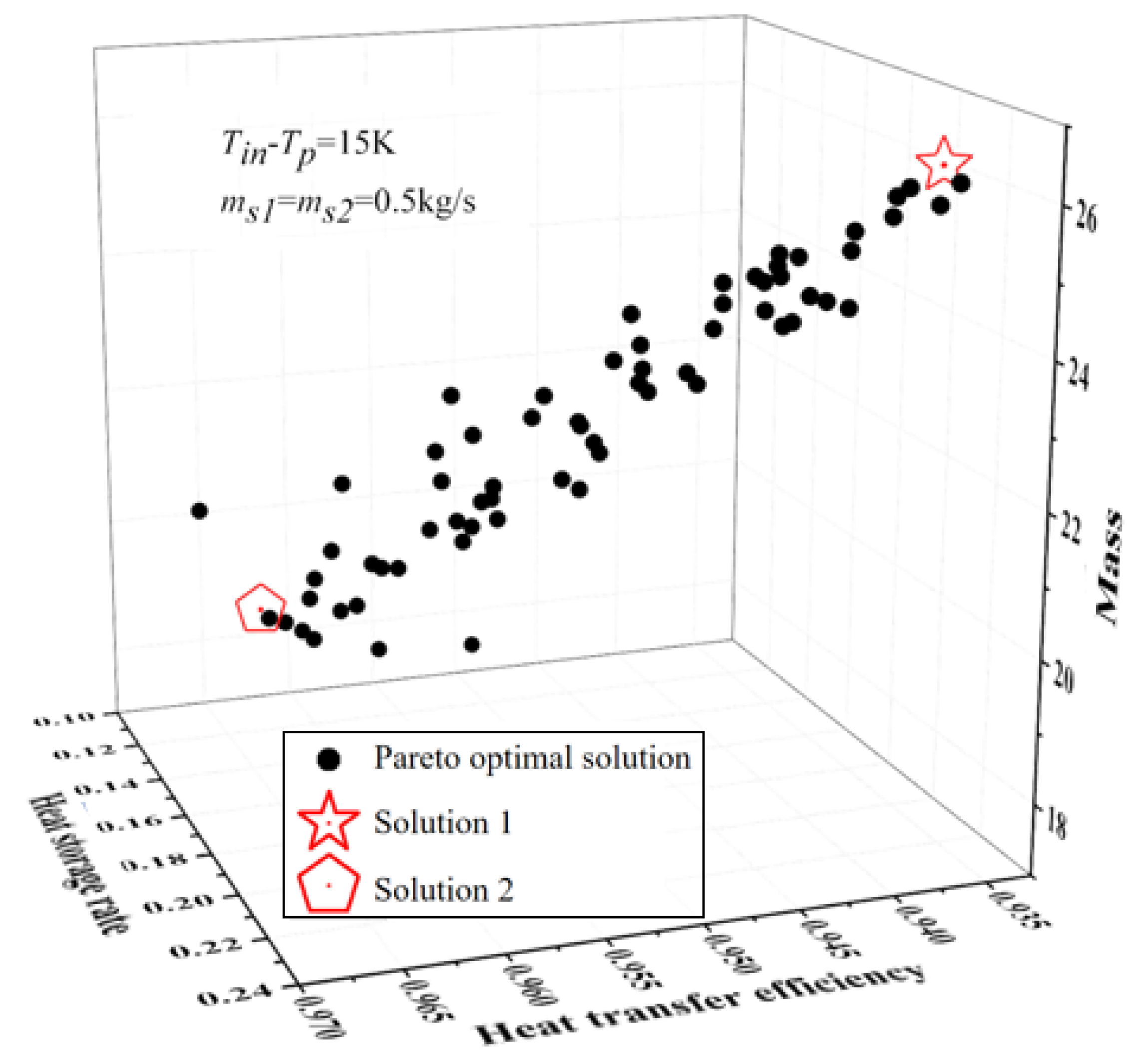
3.2. Optimization Outcomes

The calculated Pareto optimal solution set is shown in Figure 5. The design variable values and objective function evaluations at the Pareto frontier extremes are summarized in Table 5. As the PCM layer thickness decreases and the outer tube radius increases, the heat transfer efficiency ( ε ) slightly declines while the heat storage rate ( P t ) and unit mass (M) significantly increase. Conversely, thicker PCM layers and smaller outer tube radii improve ε but reduce P t and decrease M. The extreme values on the Pareto front reveal that improvements in heat transfer efficiency and unit mass reduction come at the cost of reduced thermal storage rate.
The corresponding optimized structural dimensions are r 1 = 0.014 m, r 2 = 0.041 m, and r 3 = 0.052 m. Compared with the initial design, the optimized unit exhibits a 0.35% improvement in heat transfer efficiency, a 35.87% increase in heat storage rate, and a 1.58% reduction in mass, demonstrating superior overall performance.
An integrated module was formed by serially connecting the inner and outer tubes of triplex-tube thermal storage units. This design extends the HTF flow path, enabling more complete heat release from the PCM and enhancing thermal supply capacity. As shown in Table 6, after assembling three triplex-tube phase change thermal storage units into an integrated module, the heat transfer efficiency increased from 0.9429 to 0.9633, a relative improvement of 2.12%, while the mass increased proportionally. The heat storage rate showed a more significant enhancement, rising from 0.1234 to 0.4609, a 73.23% improvement.

3.3. Influence of Geometric Parameters

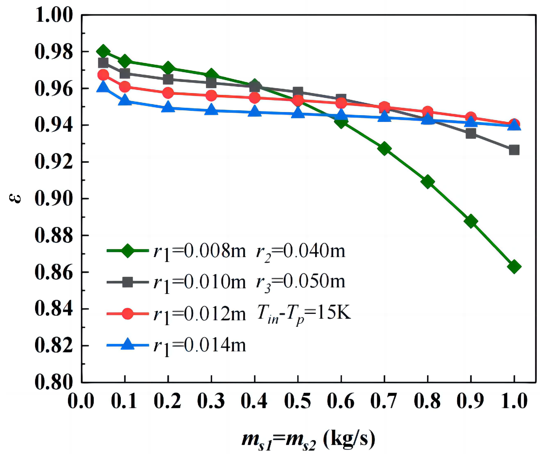
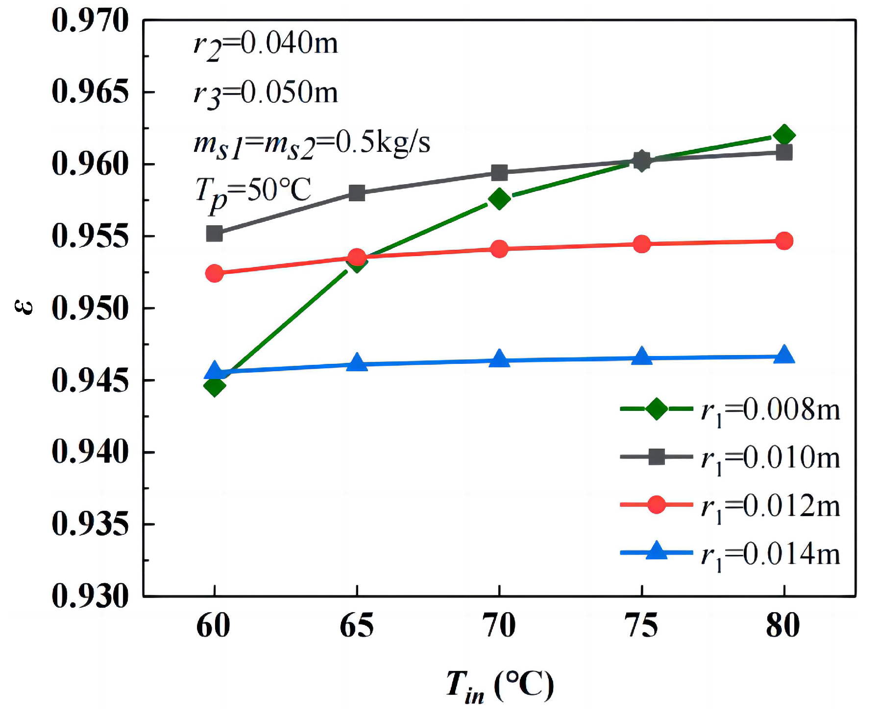
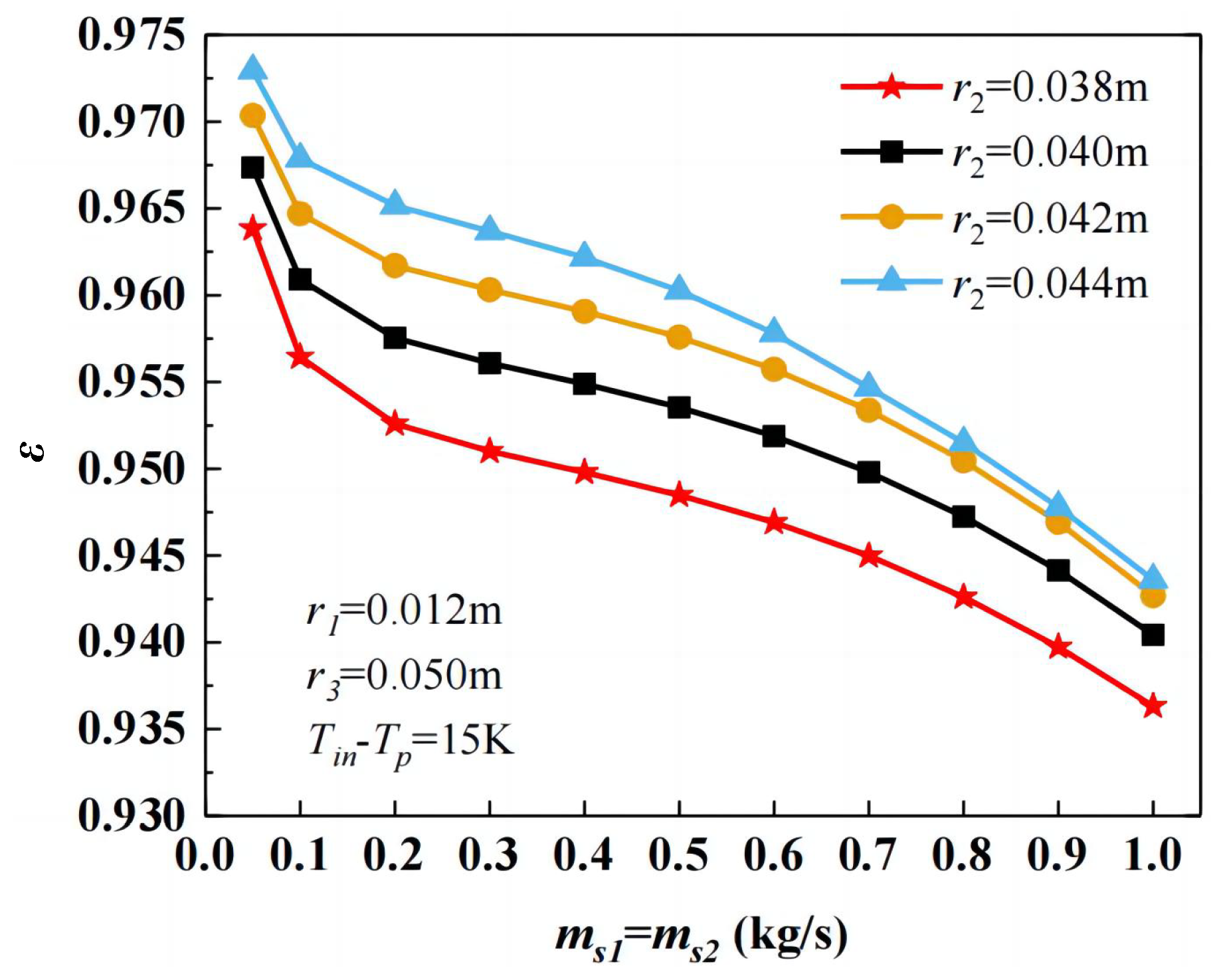
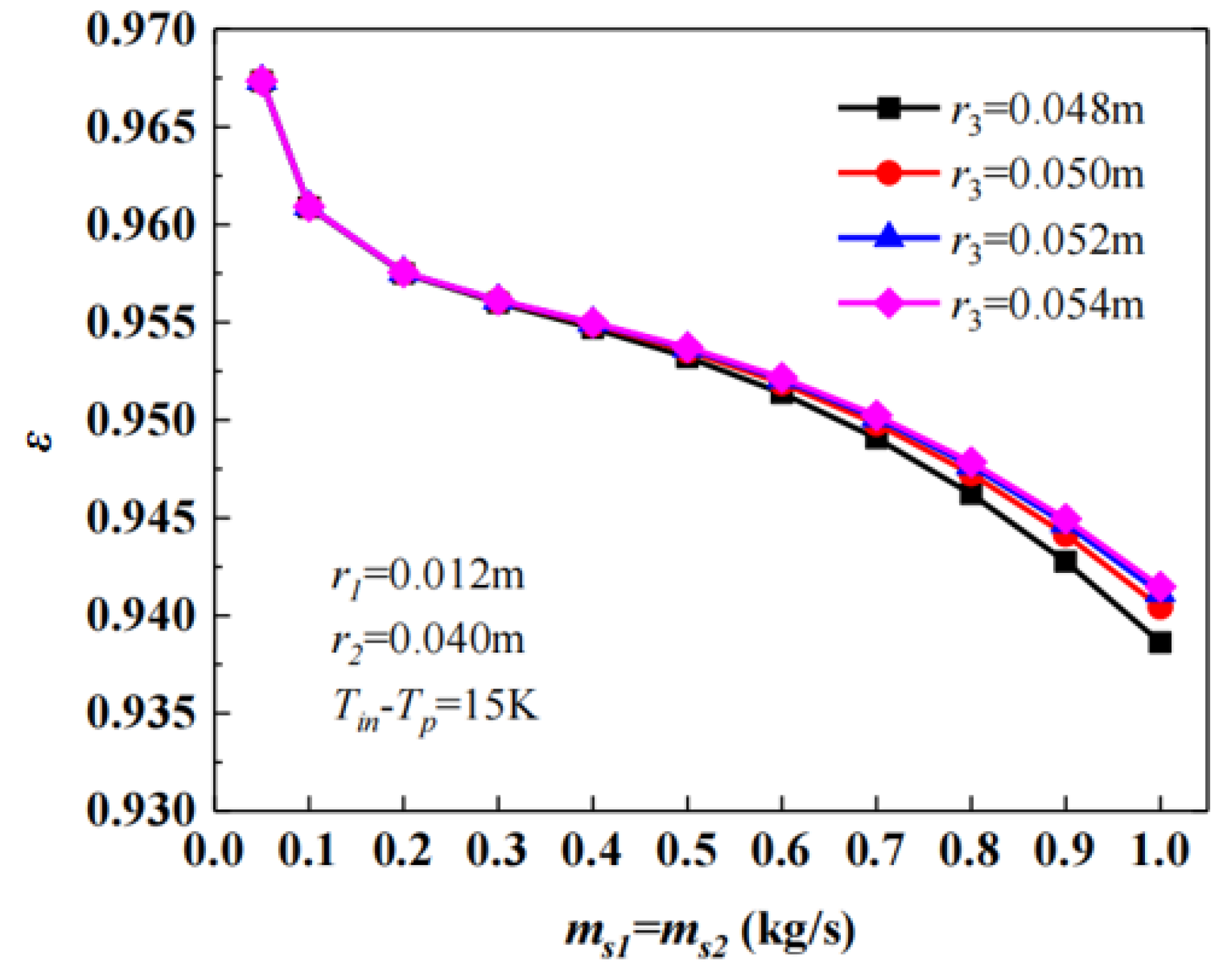
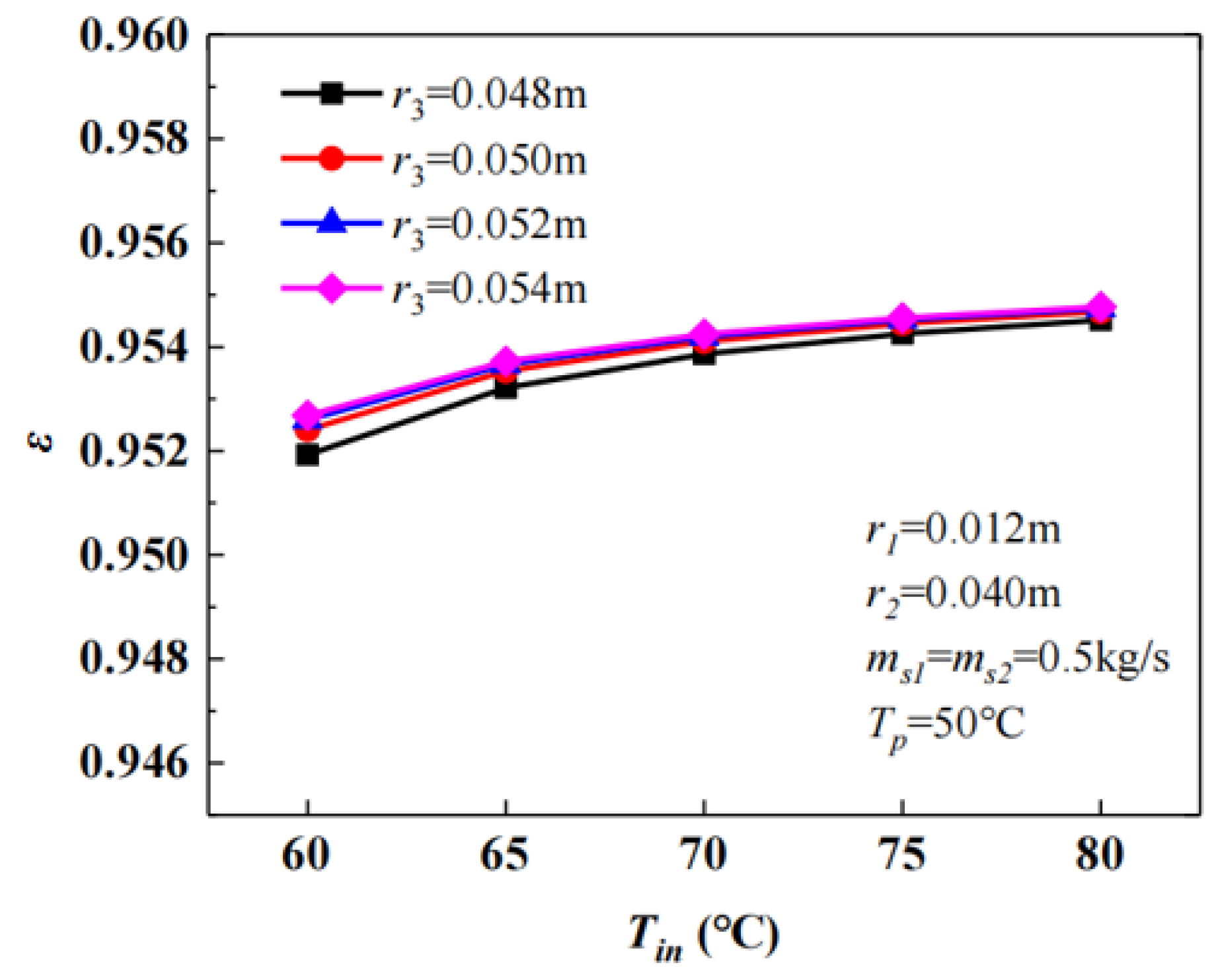
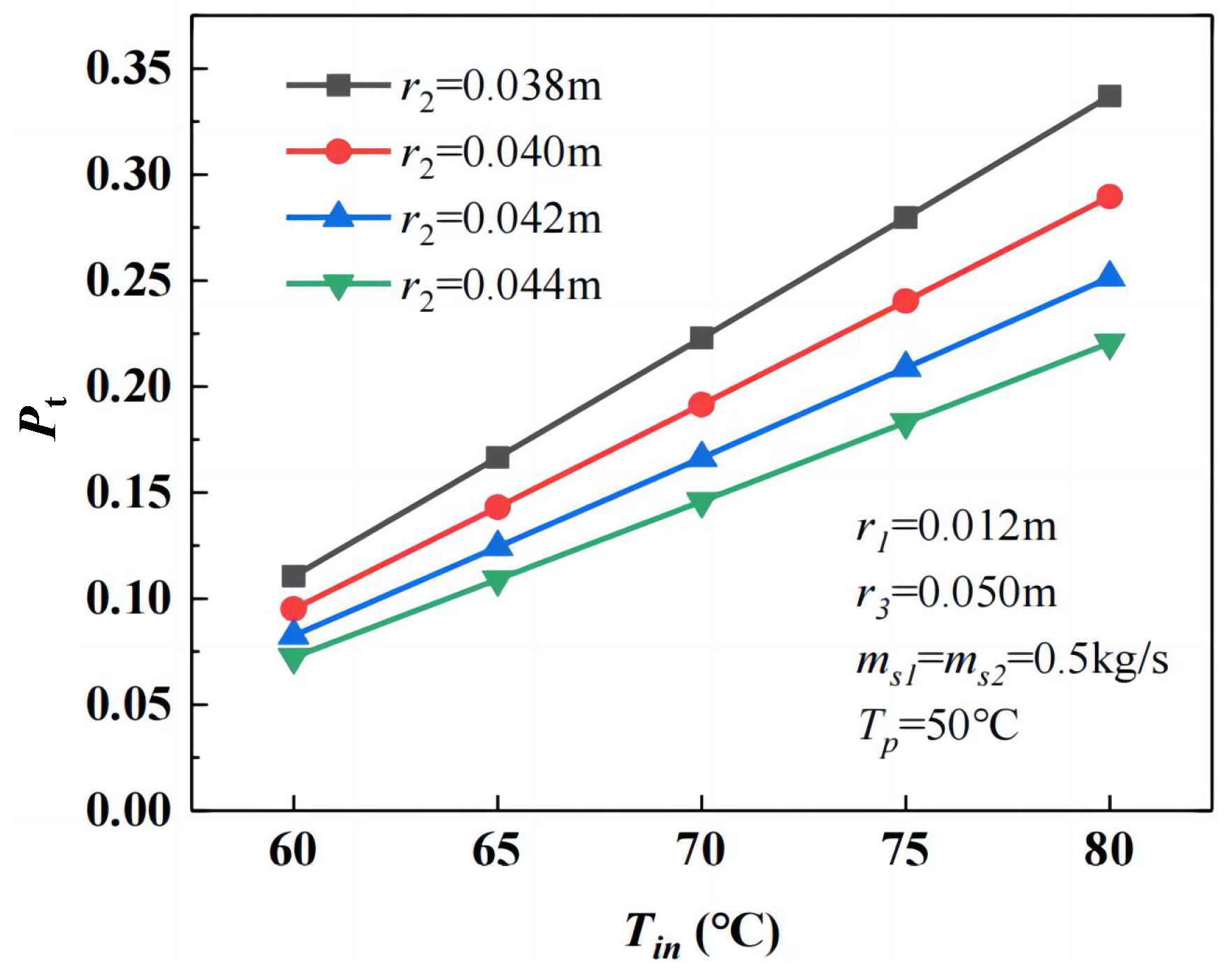
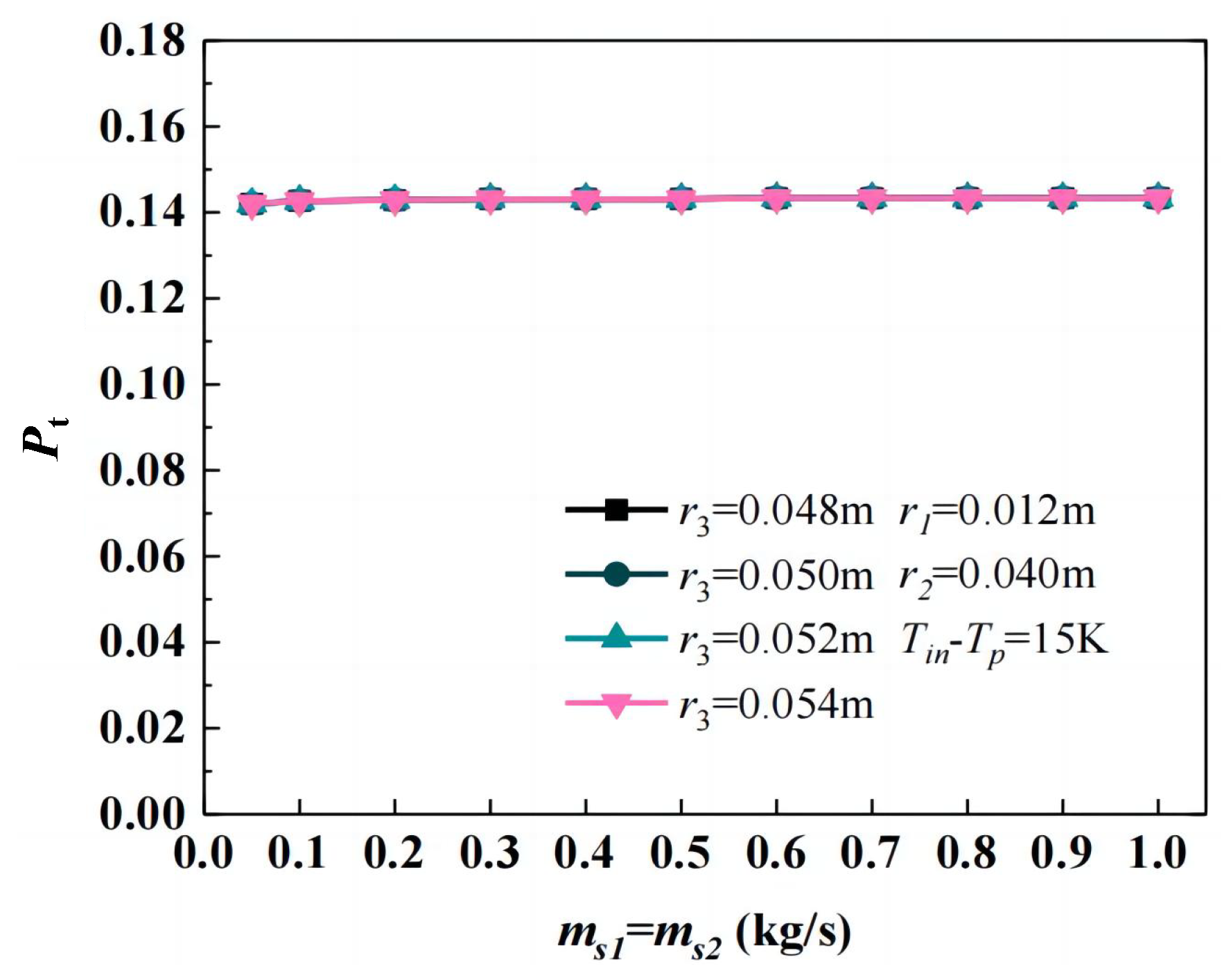
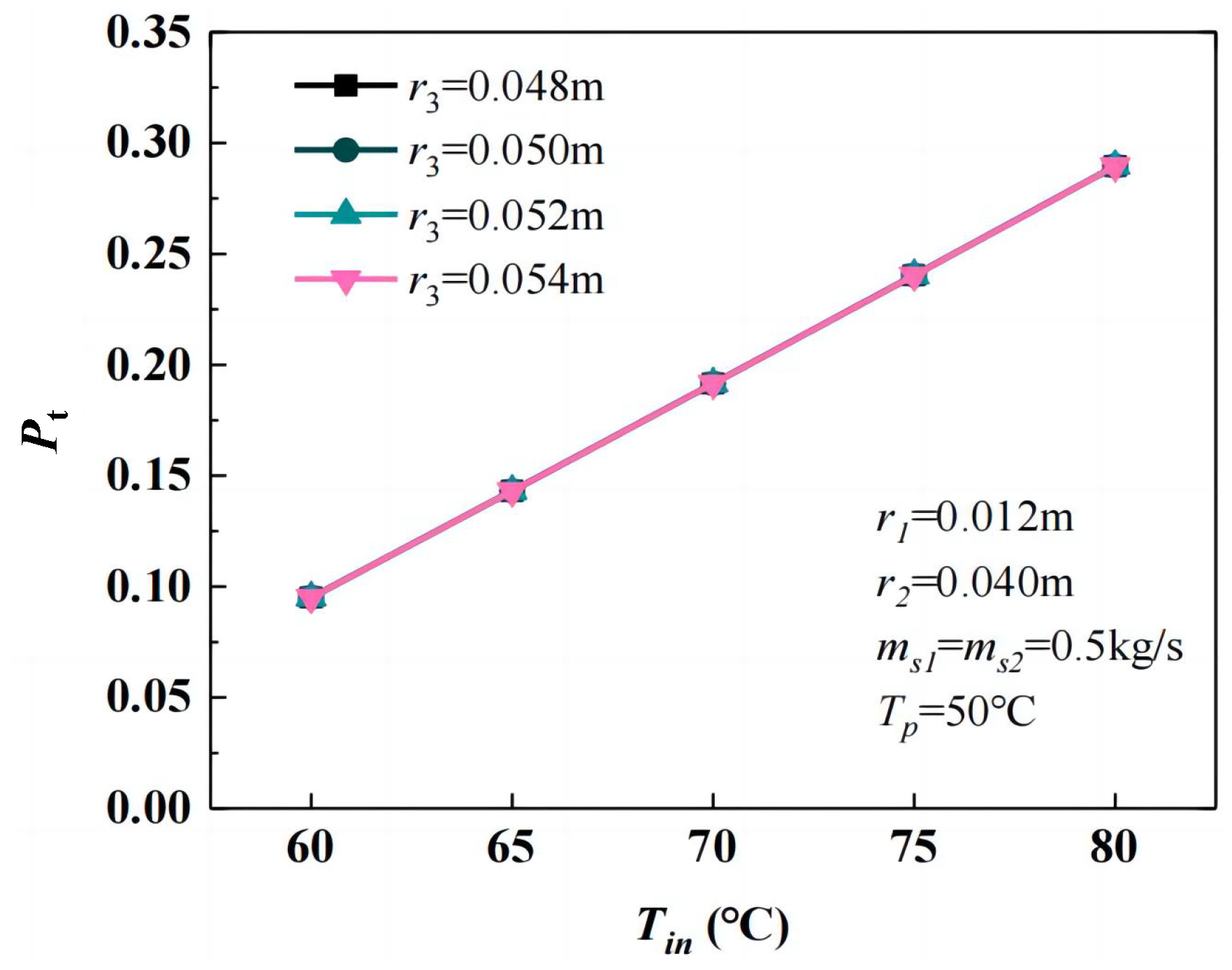
3.3.1. Heat Transfer Efficiency ε

Figure 6 demonstrates the relationship between heat transfer efficiency ( ε ) and inlet mass flow rate ( m s ) across different inner tube radii ( r 1 ). At lower mass flow rates, a reduction in the inner tube radius slightly improves heat transfer efficiency with minimal configuration differences. However, when the mass flow rate experiences a substantial increase, the heat transfer efficiency shows a notable decline, especially pronounced in configurations with smaller inner tube radii.
Figure 7 reveals that the inner tube radius ( r 1 ) increases with higher inlet HTF temperature ( T i n ), showing more pronounced improvements for a smaller inner tube radius. However, the r 1 = 0.008 m case exhibits an anomalous trend: heat transfer efficiency decreases at lower T i n due to elevated pump power consumption required to overcome resistance losses. At T i n = 80 °C, the influence of the inner tube radius on pump power diminishes, and thermal input becomes the dominant affecting factor.
The effects of the casing tube radius ( r 2 ) are illustrated in Figure 8 and Figure 9. Figure 8 shows that increasing the casing tube radius for a fixed inlet mass flow rate leads to higher heat transfer efficiency. Conversely, when the casing tube radius remains constant, increasing the inlet mass flow rate results in elevated pressure losses and thermal input in the system, thereby reducing heat transfer efficiency. Figure 9 demonstrates that heat transfer efficiency improves with higher inlet HTF temperatures. Larger casing tube radii consistently provide better performance across all temperature ranges.
Figure 10 and Figure 11 examine the influence of the outer tube radius ( r 3 ) on heat transfer efficiency. Figure 10 indicates that outer tube radius variations have a minimal impact at low inlet mass flow rates. However, when inlet mass flow rates exceed 0.6 kg/s, the effect becomes significant, with smaller outer tube radii resulting in substantially reduced efficiency due to increased pressure losses. Figure 11 demonstrates that a larger outer tube radius consistently enhances heat transfer efficiency under identical HTF inlet temperatures.

3.3.2. Heat Storage Rate
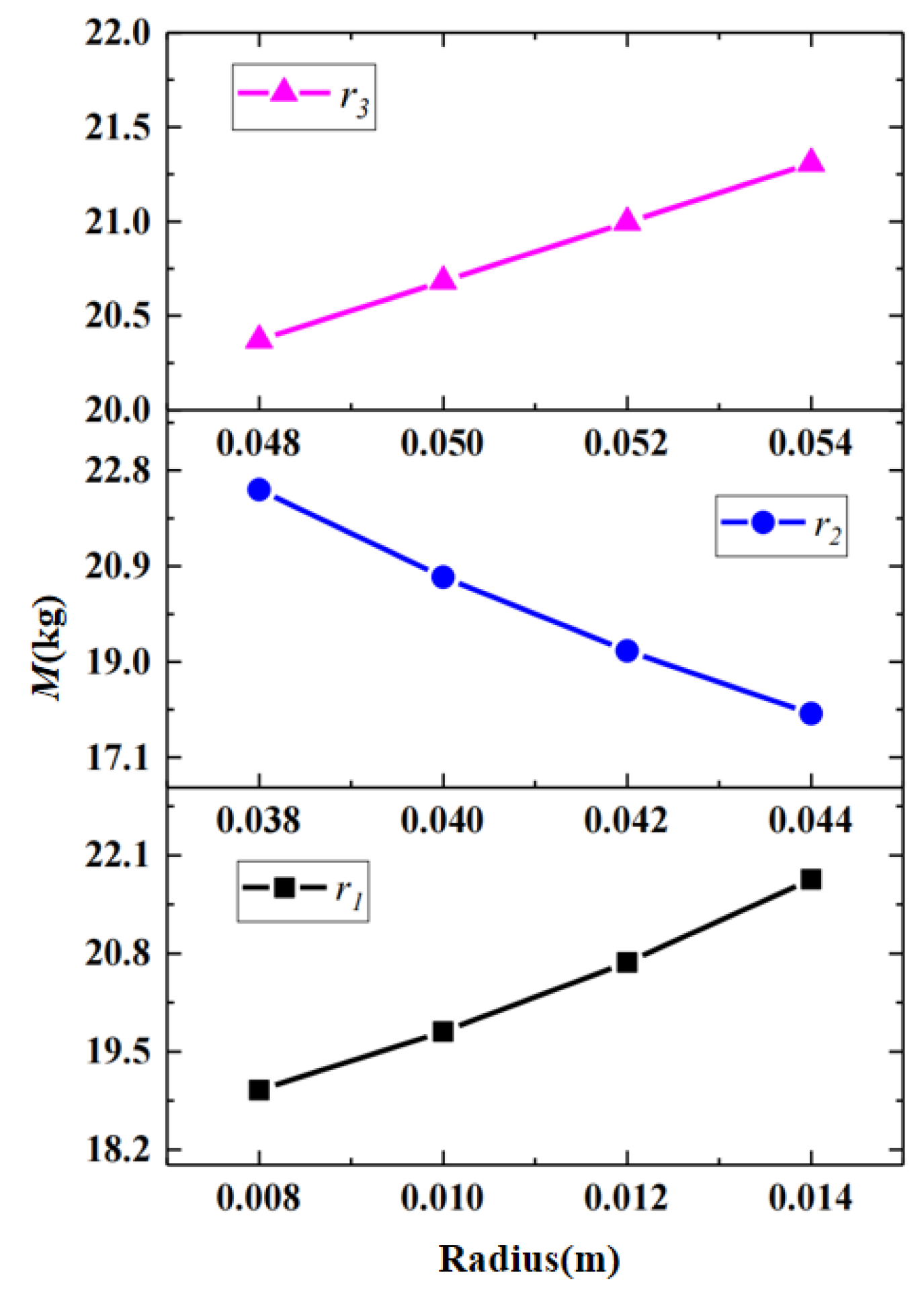
 P t

Figure 12 and Figure 13 illustrate the variation of the heat storage rate ( P t ) with inlet mass flow rate and inlet HTF temperature under different inner tube radii ( r 1 ). The results indicate that a larger r 1 significantly enhances P t . When other structural parameters remain unchanged, a larger inner tube radius leads to a thinner phase change material layer. This reduction in the PCM layer thickness shortens the time needed to complete the latent heat storage process and simultaneously boosts the heat storage rate.
Figure 14 and Figure 15 reveal an inverse relationship between P t and casing tube radius ( r 2 ). This is attributed to the increased thickness of the PCM layer when r 2 expands while keeping r 1 constant, which prolongs the phase change duration and reduces P t .
Figure 16 and Figure 17 reveal that changes in the outer tube radius ( r 3 ) have no discernible impact on P t .
Therefore, the main structural parameters that affect the heat storage rate of the triplex-tube phase change heat storage and heat transfer unit are the inner tube radius and the casing tube radius.

3.3.3. Unit Mass M

Figure 18 illustrates the variation in the unit mass (M) of the triple-tube thermal energy storage unit with structural dimensions: M increases significantly with a larger inner tube radius, decreases as the casing tube radius expands, and shows a positive correlation with the outer tube radius.

3.4. Performance Characteristics of Integrated Module

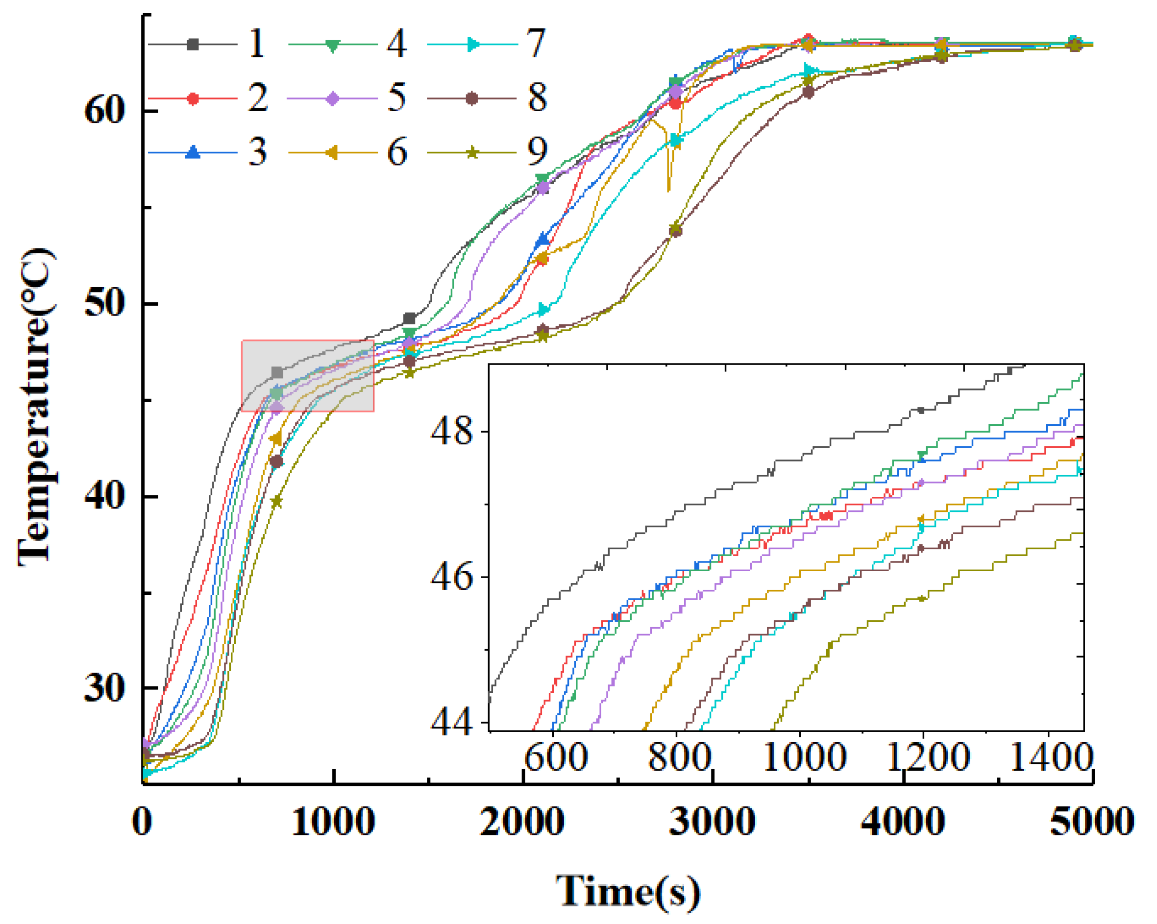
3.4.1. Heat Storage Dynamics

The thermal energy storage process of the integrated module was analyzed under low inlet flow conditions (Case 1-7). The temperature trends at measurement points 1–9 during the charging process are shown in Figure 19. The phase change process can be divided into the following three distinct stages: (1) Initial Sensible Heat Storage Stage: A rapid temperature rise occurs due to the large temperature difference between the PCM and HTF, driving efficient heat transfer via conduction. (2) Latent Heat Storage Stage: The temperature increase slows as the PCM absorbs latent heat during the phase change process. (3) Post-Phase Change Stage: After most of the latent heat is stored, the temperature rises rapidly, albeit at a reduced rate due to the diminished temperature gradient.
The temperature distribution along the flow path showed a consistent trend: temperatures decreased along the flow direction, and the onset of the phase change was delayed progressively. This pattern is particularly evident during the initial sensible heat storage stage and the early phase change. Natural convection became dominant during the later stages of the phase change, as molten PCM moved upward due to buoyancy, while unmelted or partially melted PCM sank. Minor deviations in temperature readings were observed, likely due to the displacement of temperature sensors or the presence of unmelted PCM particles during natural convection.

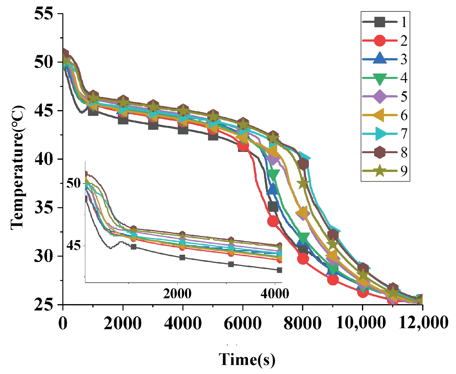
3.4.2. Heat Release Dynamics

The temperature variation during the heat release process was analyzed under experimental Case 2-5 (HTF inlet temperature: 25 °C; inner tube flow rate: 0.2 m3/h; and outer tube flow rate: 0.8 m3/h). As shown in Figure 20, the heat release process can be divided into the following three main stages: (1) Initial sensible heat release stage: The PCM temperature rapidly decreases to near the phase change temperature due to the large temperature difference between the PCM and HTF, resulting in the steepest temperature drop. (2) Latent heat release stage: The PCM reaches its solidification temperature, and the heat released to the HTF comes from the latent heat of solidification, leading to a relatively stable temperature plateau around 45 °C. (3) Final sensible heat release stage: After the phase change is complete, heat transfer reverts to sensible heat exchange, causing a sharp drop in temperature, though the rate of decrease slows due to the reduced temperature difference between the PCM and HTF.
The temperature trends at different measurement points show that the onset of the temperature plateau is delayed progressively along the flow path. In the initial stage, heat transfer is dominated by conduction as only a small amount of PCM near the tube wall solidifies. As the temperature approaches the phase change range, natural convection becomes dominant due to the density differences between solid and liquid PCM. In the final stage, conduction becomes the primary heat transfer mechanism after the PCM fully solidifies.

3.4.3. Heating Capacity Response Characteristics

The thermal supply capacity is reflected in both supply temperature and duration. This study investigated the response characteristics of the thermal storage unit under different HTF operating cases. Figure 21 shows the HTF inlet–outlet temperature difference versus time at various heat release temperatures. When the heat release temperatures are 25 °C, 32 °C, 35 °C, and 40 °C, the durations during which the temperature difference between the fluid inlet and outlet exceeds 2 °C are 6600 s, 8100 s, 9300 s, and 9400 s. As the heat release temperature increases, the supply duration extends while the temperature difference decreases. Lower heat release temperatures enhance heat exchange between HTF and PCM, yielding more significant temperature differences but shorter effective supply durations.
Table 7 presents the duration with temperature differences exceeding 2 °C under different volume flows. Comparing Cases 2-2 and 2-5 to 2-8 reveals that moderately reducing the HTF flow rate during heat release extends supply duration and enhances PCM heat release performance. Cases 2-5 and 2-6 demonstrate that increasing the outer tube flow proportion improves thermal supply effectiveness.

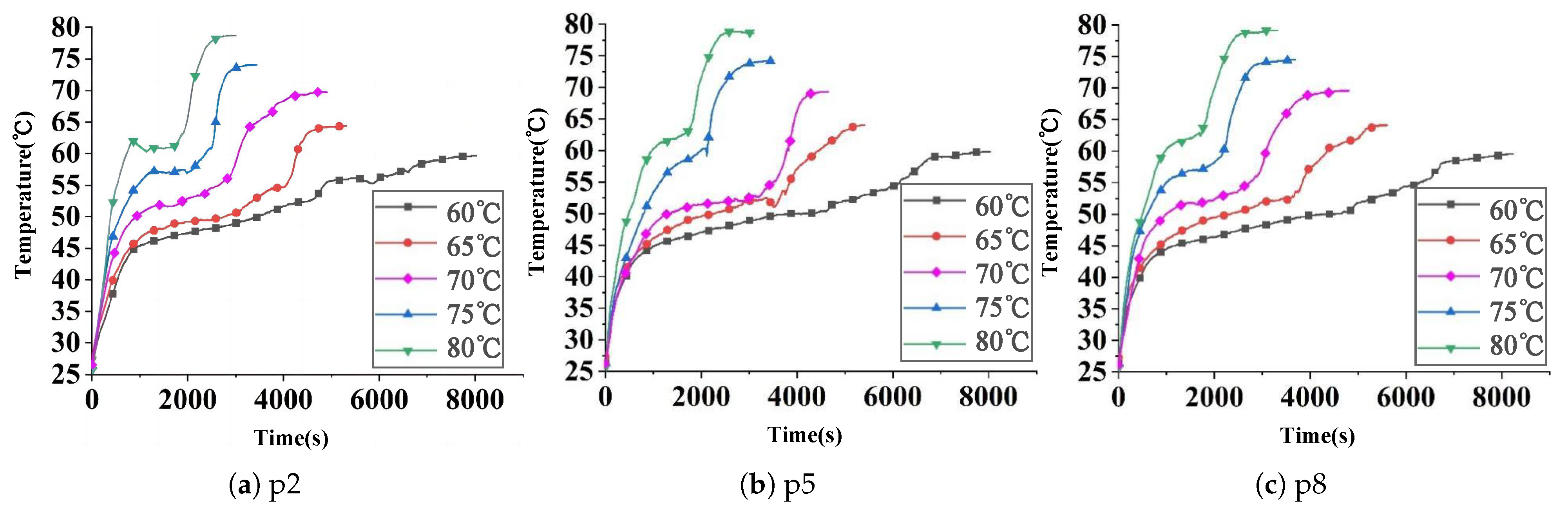
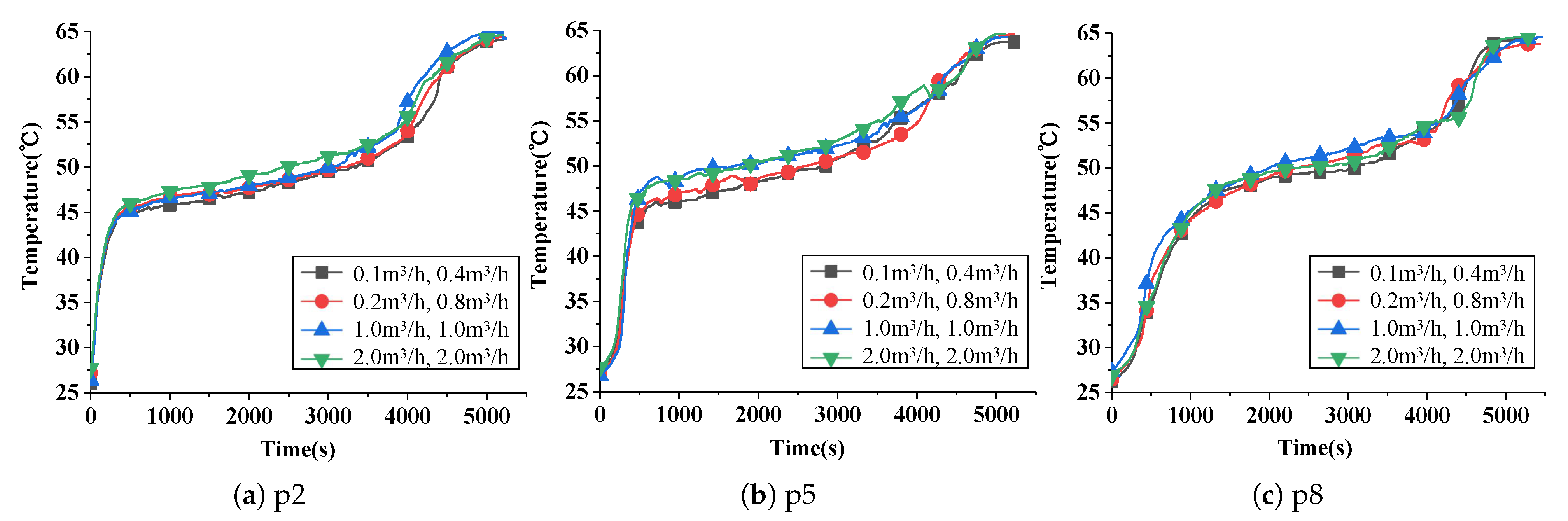
3.4.4. Influence of Flow Parameters on Heat Storage Process

Experiments for Cases 1-1 to 1-5 were conducted at HTF heat storage temperatures ranging from 60 °C to 80 °C (5 °C intervals), with inner and outer tube HTF flow rates fixed at 1 m3/h. Figure 22 shows the temperature variations over time at points p2, p5, and p8, revealing the dynamic effects of HTF heat storage temperature. As shown in Figure 22a, the temperature evolution at point p2 (representing thermal exchange unit 1) demonstrates the heat storage process under varying HTF temperatures. The heat storage completion times for temperature increments of 5 °C are approximately 8020 s, 5300 s, 4480 s, 3410 s, and 3030 s. Figure 22b illustrates the temperature variation at point p5 (unit 2), with corresponding heat storage completion times of approximately 8100 s, 5370 s, 4710 s, 3500 s, and 3160 s. Similarly, Figure 22c presents the temperature profile at point p8 (unit 3), where the heat storage completion times are approximately 8340 s, 5620 s, 4860 s, 3720 s, and 3290 s. It can be seen from the figure that the heat storage time increases with distance from the HTF inlet, and higher HTF temperatures significantly reduce heat storage duration. As the inlet temperature increased from 60 °C to 65 °C, the heat storage times at points p2, p5, and p8 decreased by 33.8%, 33.3%, and 32.5%, respectively. Similarly, when the inlet temperature rose from 75 °C to 80 °C, the times required at points p2, p5, and p8 dropped by 11.8%, 11.4%, and 10.8%, respectively. Evidently, enhancing the HTF inlet temperature proves more effective in shortening the heat storage time under lower heat storage temperature conditions.
Cases 1-4 and 1-6 to 1-8 illustrate the impact of HTF volume flow on heat storage performance. At a constant HTF temperature of 65 °C, Table 8 lists the corresponding Reynolds numbers. Figure 23 shows the temperature variations over time at points p2, p5, and p8. When the volume flow rate of the inner pipe is increased from 0.1 m3/h to 2.0 m3/h and the outer pipe is increased from 0.4 m3/h to 2.0 m3/h, the reduction in the completion time of the thermal storage process is less than 1%. Comparing laminar and turbulent flows, temperature curves at p2, p5, and p8 show that the temperature variation curves in units (1)–(3) exhibit consistent trends, indicating that increasing flow rate has limited influence on heat storage performance, though turbulent flow results in higher overall temperatures in the units.

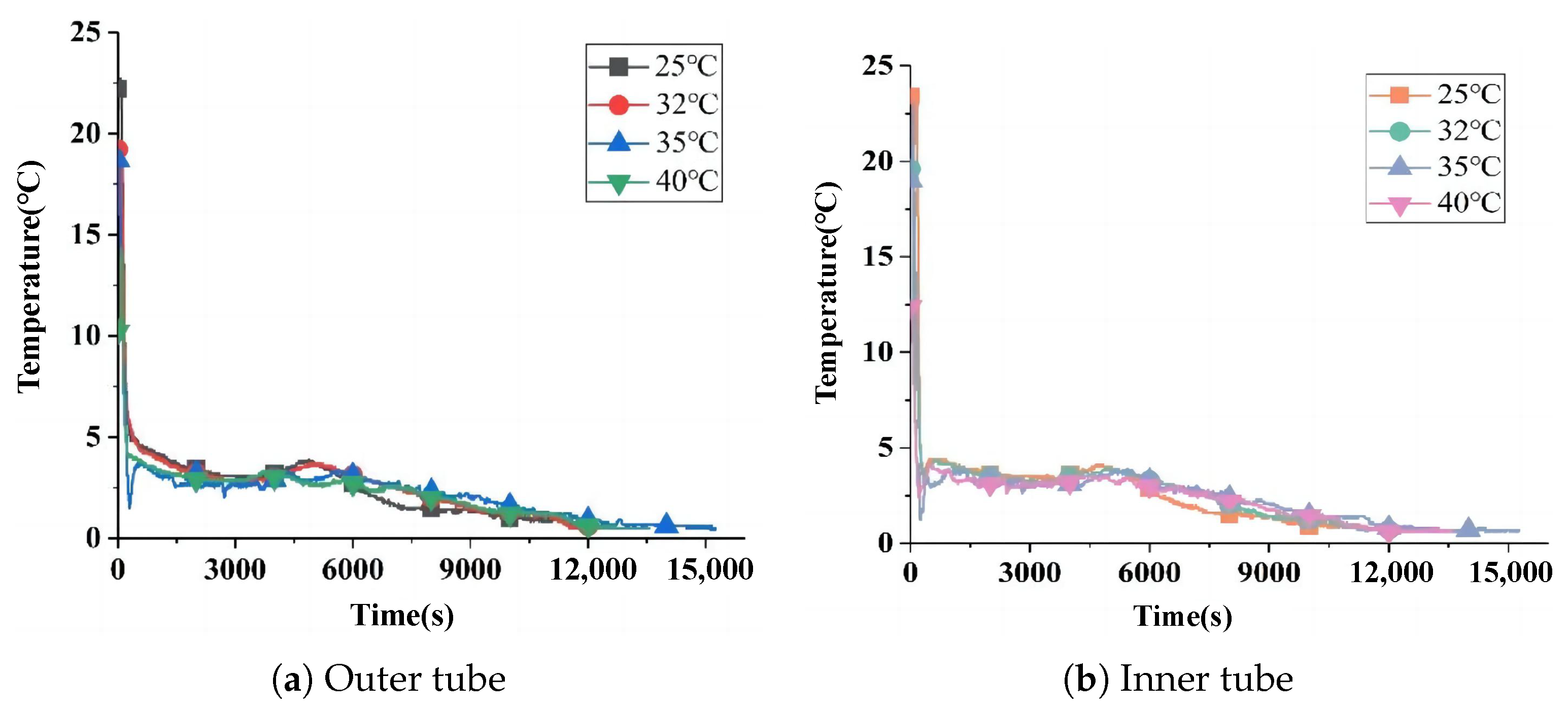
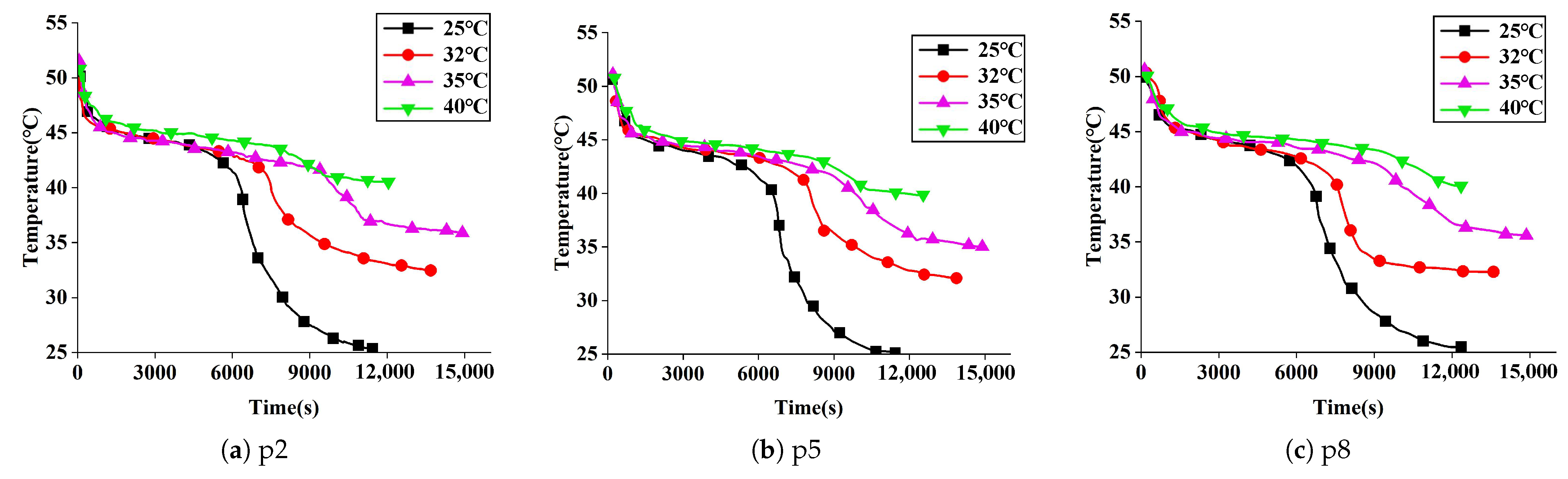
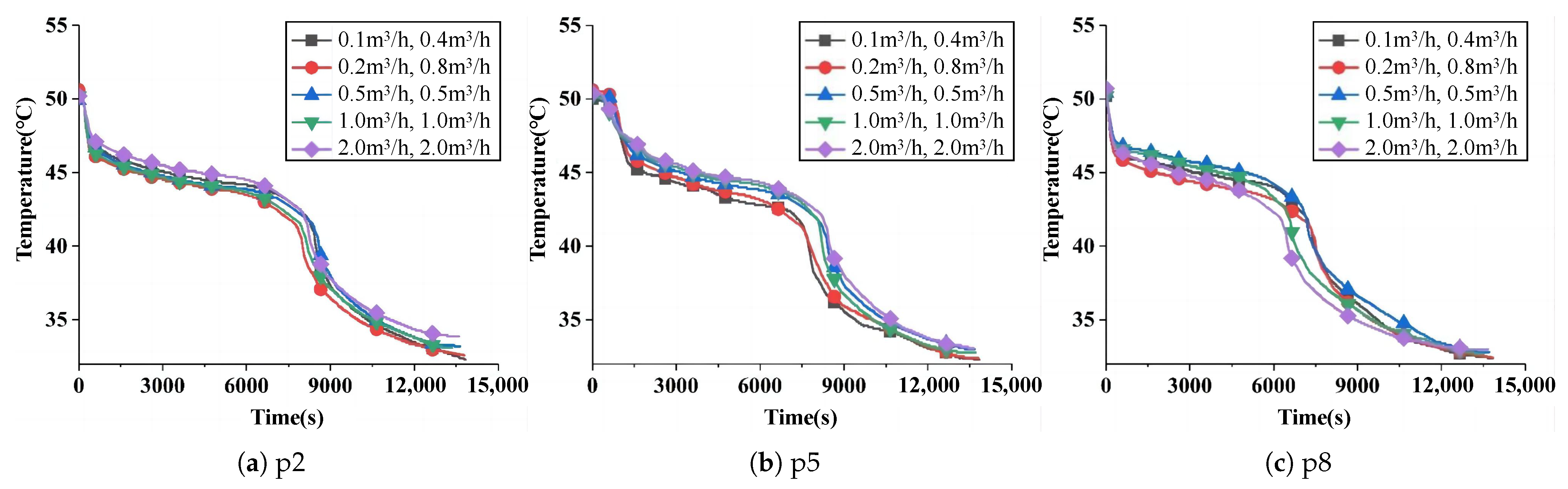
3.4.5. Influence of Flow Parameters on Heat Release Process

Cases 2-1 to 2-4 illustrate the influence of heat release temperature on the process. Figure 24 shows temperature variations at points p2, p5, and p8, representing PCM temperature changes in units 1 to 3. The time required to stabilize PCM temperature varies significantly depending on the heat release temperature. In thermal exchange unit (1), represented by p2, the PCM temperature decreases from 50 °C to 25 °C, 32 °C, 35 °C, and 40 °C in approximately 11,500 s, 13,800 s, 15,200 s, and 12,800 s, respectively. Similarly, in unit 2, represented by p5, the stabilization times under the same heat release temperatures are approximately 11,700 s, 13,900 s, 15,500 s, and 12,950 s. For unit 3, represented by p8, the corresponding stabilization times are approximately 12,000 s, 14,100 s, 15,700 s, and 13,100 s. The time required to complete the heat release process significantly extends as the heat release temperature increases from 25 °C to 35 °C. However, at 40 °C, the heat release time decreased.
Cases 2-2 and 2-5 to 2-8 investigate the dynamic effects of HTF flow regime and volume flow rate during heat release. Table 9 lists the corresponding Reynolds numbers, while Figure 25 shows the time required for PCM to reach near heat release temperature under different flow rates. Under Case 2-2, the heat release time is 14,100 s, while for Cases 2-5 to 2-8, the corresponding heat release times are 13,800 s, 13,600 s, 13,550 s, and 13,580 s, respectively. Similar to the findings in heat storage scenarios, the heat release time of the phase change thermal storage unit exhibits limited sensitivity to variations in volume flow rates.

4. Discussion

4.1. Practical Implications

When compared with single-objective optimization methods, NSGA-II generally demands a larger population size and a greater number of iterations. In the context of this study, although there are only three design variables, namely, r 1 , r 2 , and r 3 , the objective functions, which are ε , P t , and M, exhibit significant conflicts. These conflicts make it extremely challenging for traditional and simple optimization techniques to effectively address such problems. NSGA-II, with its ability to handle multiple conflicting objectives simultaneously, becomes a more suitable choice. Experimental and numerical results demonstrate that the geometric optimization of the triplex-tube phase change thermal storage unit significantly enhances its thermal performance. The optimized configuration ( r 1 = 0.014 m, r 2 = 0.041 m, and r 3 = 0.052 m) improved heat transfer efficiency by 0.35%, increased temporal efficiency by 35.87%, and reduced mass by 1.58%. After assembling the triplex-tube phase change thermal energy storage unit into an integrated module, the mass was proportionally enlarged, the heat transfer efficiency was increased by 2.12%, and the heat storage rate was increased by 73.23%. The multi-objective optimization of the triplex-tube thermal energy storage unit using a genetic algorithm proved feasible for structural dimension optimization. While the proposed system shows good short-term performance, practical applications require durability assessment under cyclic heat loads and ambient stress. Realistic applications still require experimental verification under actual aging conditions.

4.2. Influence of Structural Parameters

The analysis reveals critical trade-offs between heat transfer efficiency, heat storage rate, and mass of the heat transfer unit. The inverse relationship between heat transfer efficiency and inner tube radius at high flow rates stems from conflicting effects: a smaller inner tube radius enhances convective heat transfer via increased flow velocity but amplifies frictional losses, disproportionately raising pump power consumption. A larger casing tube radius improves heat transfer efficiency by expanding the annulus flow area, reducing turbulence-induced pressure losses. While an outer tube radius has minimal impact at low mass flow rates, its reduction significantly degrades heat transfer efficiency under high-flow conditions due to intensified outer tube resistance.
The positive correlation between heat storage rate and inner tube radius arises from reduced PCM layer thickness, which shortens latent heat storage time. In contrast, increasing r 2 thickens the PCM layer, prolonging the phase change duration and diminishing the heat storage rate. Notably, the outer tube radius exhibits no measurable influence on P t , as it primarily defines external boundaries rather than PCM geometry. For system mass, the antagonistic effects of an inner tube radius (increasing mass) and a casing tube radius (decreasing mass) reflect their opposing roles in structural material volume, while a larger outer tube radius increases mass due to additional outer shell material.

4.3. Dynamic Heat Storage/Release Behavior

This study reveals that HTF parameters, including temperature and volume flow rate, play a critical role in system performance. Higher HTF temperatures during heat storage significantly reduce the time required for PCM melting, while increasing the HTF temperature within a reasonable range during heat release extends the heat release time. However, the impact of volume flow rate on thermal performance is less pronounced, particularly during heat release, where turbulent flow regimes only marginally improve heat transfer compared with laminar flow. This suggests that while flow optimization is beneficial, geometric design and temperature control are more influential factors in enhancing system performance.
The thermal supply capacity demonstrates significant sensitivity to heat release temperature. Lowering the heat release temperature increases the temperature difference between the HTF inlet and outlet, indicating more efficient heat exchange between the HTF and PCM. However, this comes at the cost of reduced heat supply duration. Optimizing the heat release temperature is crucial for balancing heat exchange efficiency and heat supply duration in practical applications. This study also investigated the effects of flow distribution between the inner and outer tubes. Increasing the flow proportion in the outer tube improves heat exchange efficiency, thereby enhancing thermal supply performance. This finding underscores the importance of optimizing flow distribution in multi-tube phase change thermal storage systems to achieve more uniform heat release and higher thermal efficiency.

4.4. Limitations

While this study provides valuable insights into the response characteristics of phase change thermal storage systems, future research could further explore the effects of other phase change materials or wall modifications on heat exchanger performance. For the numerical model, the current model assumes that the flow is in steady state and does not consider the transient pressure losses caused by rapid flow acceleration/deceleration or valve actuation. This simplified approach may underestimate the actual power demand. The quantitative results of latent and sensible heat in the phase transition process are not considered, which may limit the practical application of thermal load regulation. Additionally, the integration scale of the triplex-tube phase change thermal storage units was not thoroughly investigated, warranting economic analysis to optimize the integration scale. Furthermore, this study does not consider the performance degradation after long-term operation. This simplification may overestimate the long-term efficiency of the system operation. Long-term experimental validation under real-world conditions is necessary to assess the practical applicability of the proposed optimization strategies.

5. Conclusions

This study focused on optimizing the geometric design of a triplex-tube thermal energy storage system for clean heating applications. A multi-objective optimization method based on NSGA-II was developed, providing a practical approach for structural dimension optimization. The method proposed in this study can effectively improve the comprehensive performance of phase change heat storage heat exchangers, avoiding the high cost of repetitive experiments and effectively meeting the user’s demand for high-efficiency heat storage and lightweight design. The key findings are summarized as follows:
1.
For a phase change temperature of 50 °C, the optimal configuration ( r 1 = 0.014 m, r 2 = 0.041 m, and r 3 = 0.052 m) outperforms the original design, with a 0.35% improvement in heat transfer efficiency, a 35.87% increase in heat storage rate, and a 1.58% mass reduction, demonstrating superior overall performance. Integrating multiple units into a module enhanced heat transfer efficiency by 2.12% and heat storage rate by 73.23%, demonstrating superior performance and practicality.
2.
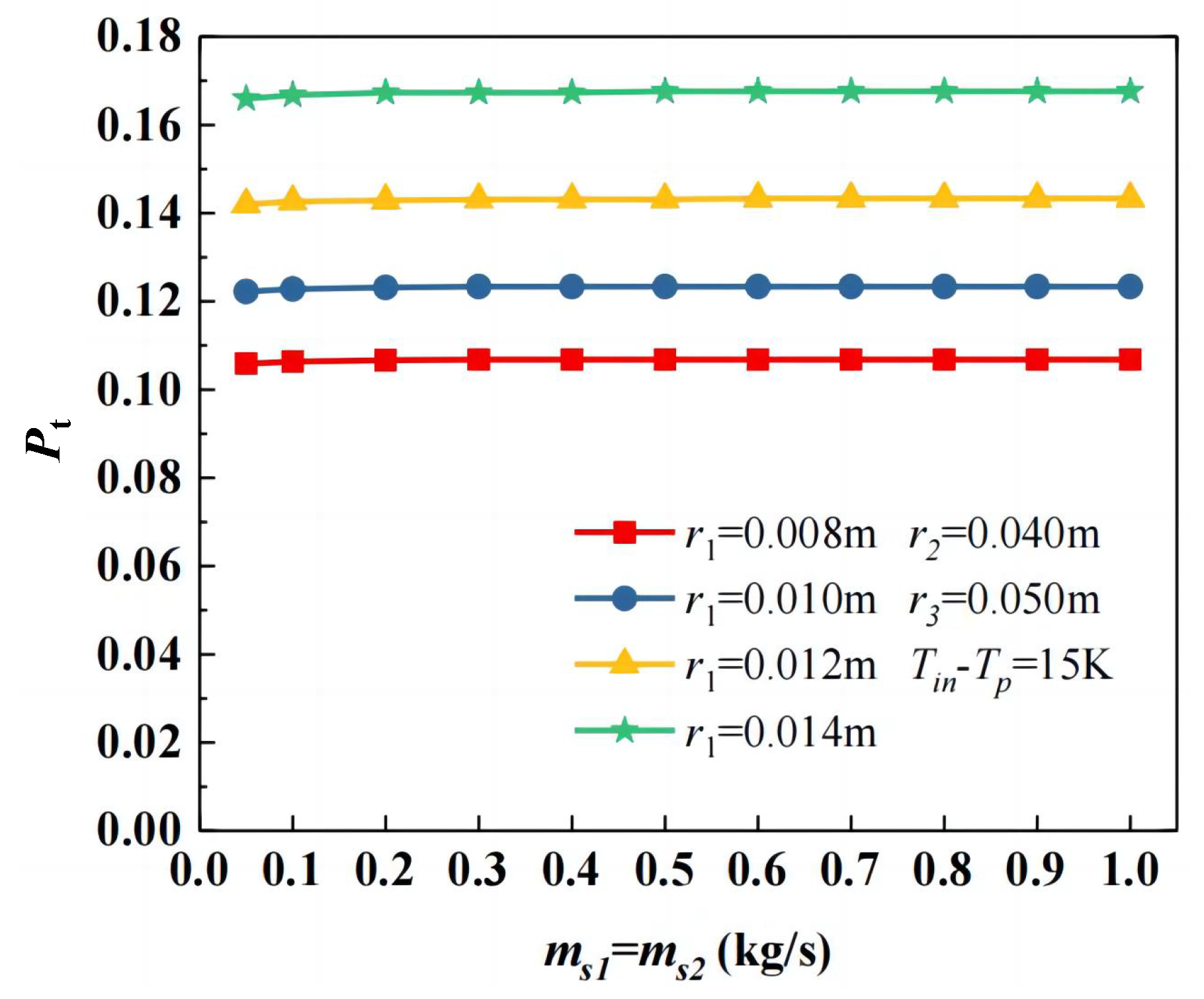
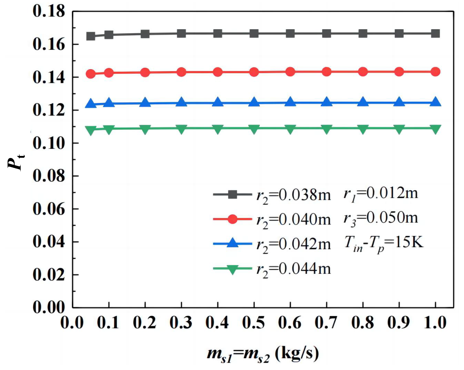
Heat transfer efficiency decreases with a larger inner tube radius but further declines if the inner tube is undersized under high mass flow rates or low inlet temperatures. Increasing the casing and outer tube radius improves efficiency, though the latter exhibits negligible effects at low flow rates. The heat storage rate increases with the inner tube radius, decreases with the casing tube radius, and remains unaffected by the outer tube radius. The system mass rises with a larger inner and outer tube radius but decreases with the expansion of the casing tube radius.
3.
Lowering heat release temperature increased the HTF temperature difference but reduced heat supply duration. Reducing the inner tube flow rate from 0.2 m3/h to 0.1 m3/h and the outer tube flow rate from 0.8 m3/h to 0.4 m3/h extended the heat supply time by 7.4%. Increasing the outer tube flow proportion improved heat exchange efficiency, achieving better thermal supply performance.
4.
Higher HTF temperatures significantly reduced heat storage time, with a 30% reduction when increasing from 60 °C to 65 °C and an 11% reduction from 75 °C to 80 °C. However, increasing HTF volume flow had a limited impact on heat storage performance, highlighting the dominant role of temperature control.
5.
Increasing heat release temperature extended PCM heat release time but reduced heat release at excessively high temperatures. Heat release time showed limited sensitivity to volume flow rate variations.

Author Contributions

Conceptualization, N.Z.; methodology, H.Y.; software, H.Y.; validation, Y.Z.; data curation, Y.Z.; writing—original draft, Y.Z.; writing—review and editing, Y.H.; visualization, Y.Z.; supervision, Y.H.; project administration, N.Z. All authors have read and agreed to the published version of the manuscript.

Funding

This research received no external funding.

Data Availability Statement

The data will be made available upon request.

Conflicts of Interest

The authors declare no conflicts of interest.

Abbreviations

The following abbreviations are used in this manuscript:
PCMphase change material
HTFheat transfer fluid
r 1 inner tube radius (m)
r 2 casing tube radius (m)
r 3 outer tube radius (m)
Ltube length (m)
Slatent heat storage (kJ)
Qheat input (kJ)
Wpump power consumption (kJ)
P t heat storage rate (kW)
Mmass (kg)
R e Reynolds number
m s inlet mass flow rate (kg/s)
c p specific heat capacity (kJ/(kg·K))
theat storage completion time(s)
Δ T inlet and outlet temperature difference (°C)
Δ p pressure losses (Pa)
d h hydraulic diameter (m)
h d PCM layer thickness (m)
Hlatent heat of phase change (kJ/kg)
T i n heat transfer fluid inlet temperature (°C)
T E phase change temperature (°C)
R 1 inner tube radius for HTF flow (m)
R 2 outer tube radius for HTF flow (m)
luser-defined maximum length (m)
ε heat transfer efficiency
δ wall thickness (m)
ρ h density of HTF (kg/m3)
ρ M density of the tubing material (kg/m3)
λ thermal conductivity(W/(m·K))
ξ friction factor
τ        user-specified time (s)

References

  1. Ullah, A.; Nobanee, H.; Ullah, S.; Iftikhar, H. Renewable energy transition and regional integration: Energizing the pathway to sustainable development. Energy Policy 2024, 193, 114270. [Google Scholar] [CrossRef]
  2. Gaboitaolelwe, J.; Zungeru, A.M.; Yahya, A.; Lebekwe, C.K.; Vinod, D.N.; Salau, A.O. Machine Learning Based Solar Photovoltaic Power Forecasting: A Review and Comparison. IEEE Access 2023, 11, 40820–40845. [Google Scholar] [CrossRef]
  3. Guo, Y.; Liang, C.; Liu, H.; Gong, L.; Bao, M.; Shen, S. A Review on Phase-Change Materials (PCMs) in Solar-Powered Refrigeration Systems. Energies 2025, 18, 1547. [Google Scholar] [CrossRef]
  4. Li, Z.; Lu, Y.; Huang, R.; Chang, J.; Yu, X.; Jiang, R.; Yu, X.; Roskilly, A.P. Applications and technological challenges for heat recovery, storage and utilisation with latent thermal energy storage. Appl. Energy 2021, 283, 116277. [Google Scholar] [CrossRef]
  5. Mika, Ł.; Radomska, E.; Sztekler, K.; Gołdasz, A.; Zima, W. Review of Selected PCMs and Their Applications in the Industry and Energy Sector. Energies 2025, 18, 1233. [Google Scholar] [CrossRef]
  6. Mahdi, J.M.; Nsofor, E.C. Solidification enhancement of PCM in a triplex-tube thermal energy storage system with nanoparticles and fins. Appl. Energy 2018, 211, 975–986. [Google Scholar] [CrossRef]
  7. Dong, X.; Zhu, C. Research on the Heat Transfer Performance of Phase Change Heat Storage Heat Exchangers Based on Heat Transfer Optimization. Energies 2024, 17, 4150. [Google Scholar] [CrossRef]
  8. Yang, X.; Guo, J.; Yang, B.; Cheng, H.; Wei, P.; He, Y.L. Design of non-uniformly distributed annular fins for a shell-and-tube thermal energy storage unit. Appl. Energy 2020, 279, 115772. [Google Scholar] [CrossRef]
  9. Leong, K.Y.; Hasbi, S.; Gurunathan, B.A. State of art review on the solidification and melting characteristics of phase change material in triplex-tube thermal energy storage. J. Energy Storage 2024, 41, 102932. [Google Scholar] [CrossRef]
  10. Hao, J.; Wu, X.; Ju, C.; Wang, X.; Hong, F.; Du, X. Bionic-response surface combination optimization method for latent heat storage performance improvement. Appl. Therm. Eng. 2024, 248, 123320. [Google Scholar] [CrossRef]
  11. Khedher, N.B.; Hosseinzadeh, K.; Abed, A.M.; Khosravi, K.; Mahdi, J.M.; Sultan, H.S.; Mohammed, H.I.; Talebizadehsardari, P. Accelerated charging of PCM in coil heat exchangers via central return tube and inlet positioning: A 3D analysis. Int. Commun. Heat Mass Transf. 2024, 152, 107275. [Google Scholar] [CrossRef]
  12. Huang, X.; Yao, S.; Yang, X.; Zhou, R. Melting performance assessments on a triplex-tube thermal energy storage system: Optimization based on response surface method with natural convection. Renew. Energy 2022, 188, 890–910. [Google Scholar] [CrossRef]
  13. Rodríguez, M.B.R.; Rodríguez, J.L.M.; Fontes, C.H.D.O. Thermo ecological optimization of shell and tube heat exchangers using NSGA II. Appl. Therm. Eng. Des. Process. Equip. Econ. 2019, 156, 91–98. [Google Scholar] [CrossRef]
  14. Srivastava, U.; Sahoo, R.R. Energy and exergy investigation of a eutectic phase change material for a triplex tube thermal energy storage with various configurations. Mater. Today Commun. 2024, 38, 108398. [Google Scholar] [CrossRef]
  15. Mahdi, J.M.; Lohrasbi, S.; Ganji, D.D.; Nsofor, E.C. Simultaneous energy storage and recovery in the triplex-tube heat exchanger with PCM, copper fins and Al2O3 nanoparticles. Energy Convers. Manag. 2019, 180, 949–961. [Google Scholar] [CrossRef]
  16. Yao, S.; Zuo, M.; Huang, X. Evaluation and Optimization of the Thermal Storage Performance of a Triplex-Tube Thermal Energy Storage System with V-Shaped Fins. J. Therm. Sci. 2023, 32, 2048–2064. [Google Scholar] [CrossRef]
  17. Choure, B.K.; Alam, T.; Kumar, R. Optimization of heat transfer in PCM based triple tube heat exchanger using multitudinous fins and eccentric tube. J. Energy Storage 2024, 102, 113981. [Google Scholar] [CrossRef]
  18. Zaytoun, M.M.; El-Bashouty, M.M.; Sorour, M.M.; Alnakeeb, M.A. Heat transfer characteristics of PCM inside a modified design of shell and tube latent heat thermal energy storage unit. Case Stud. Therm. Eng. 2023, 49, 103372. [Google Scholar] [CrossRef]
  19. Hussain, B.; Irfan, M.; Khan, M.M.; Ullah, S.; ul Hasnain, F. Geometric optimization of fin structures for accelerated melting of phase change material in a triplex tube heat exchanger. J. Energy Storage 2024, 79, 110162. [Google Scholar] [CrossRef]
  20. Yan, C.; Kumar Singh, P.; Hamlaoui, O.; hajji, M.k.; Elmasry, Y.; Redhee, A.h.; Abdullaeva, B.S.; Garalleh, H.A.L. Heat release efficiency Betterment inside a novel-designed latent heat exchanger featuring arc-shaped fins and a rotational mechanism via numerical model and artificial neural network. Case Stud. Therm. Eng. 2024, 61, 105093. [Google Scholar] [CrossRef]
  21. Ren, F.; Li, Q.; Wang, P. Investigation and optimization on a Y-shaped fins for phase change heat storage by rotational mechanism. J. Energy Storage 2024, 94, 112436. [Google Scholar] [CrossRef]
  22. Boujelbene, M.; Mahdi, J.M.; Abed, A.M.; Ghanim, M.S.; Hammoodi, K.A.; Mohammed, H.I.; Togun, H.; Talebizadehsardari, P. The potential of arch-shaped fins for energy-charge enhancement in triplex-tube heat storage: Comparative analysis and optimization. J. Energy Storage 2024, 79, 110188. [Google Scholar] [CrossRef]
  23. Wang, L.; Lei, Y.; Du, B.; Li, Y.; Sun, J. Performance enhancement of a horizontal latent thermal energy storage unit with elliptical fins. Appl. Therm. Eng. 2023, 225, 120191. [Google Scholar] [CrossRef]
  24. Boujelbene, M.; Mohammed, H.I.; Sultan, H.S.; Eisapour, M.; Chen, Z.; Mahdi, J.M.; Cairns, A.; Talebizadehsardari, P. A comparative study of twisted and straight fins in enhancing the melting and solidifying rates of PCM in horizontal double-tube heat exchangers. Int. Commun. Heat Mass Transf. 2024, 151, 107224. [Google Scholar] [CrossRef]
  25. Ren, F.; Du, J.; Cai, Y.; Guo, J.; Liu, Y.; Zhang, D.; Li, M. Study on thermal performance of a new optimized snowflake longitudinal fin in vertical latent heat storage. J. Energy Storage 2022, 50, 104165. [Google Scholar] [CrossRef]
  26. Yang, K.; Zhu, N.; Chang, C.; Yu, H.; Yang, S. Numerical analysis of phase-change material melting in triplex tube heat exchanger. Renew. Energy 2020, 145, 867–877. [Google Scholar] [CrossRef]
  27. Yang, K.; Zhu, N.; Li, Y.; Du, N. Effect of parameters on the melting performance of triplex tube heat exchanger incorporating phase change material. Renew. Energy 2021, 174, 359–371. [Google Scholar] [CrossRef]
  28. Cao, X.; Zhang, N.; Yuan, Y.; Luo, X. Thermal performance of triplex-tube latent heat storage exchanger: Simultaneous heat storage and hot water supply via condensation heat recovery. Renew. Energy 2020, 157, 616–625. [Google Scholar] [CrossRef]
  29. Sadiq, I.E.; Aljabair, S.; Karamallah, A.A. Accelerated solidification of PCM via Al2O3/CuO hybrid nanoparticles in triplex tube heat storage. J. Therm. Eng. 2021, 10, 880–903. [Google Scholar] [CrossRef]
  30. Ma, G.; Zhang, J.; Wang, J. Numerical simulation of heat transfer processes in shell and tube phase change heat exchangers for recovering industrial waste heat. Mater. Res. Express 2024, 11, 125508. [Google Scholar] [CrossRef]
  31. Khedher, N.B.; Mehryan, S.A.M.; Hajjar, A.; Alghawli, A.S.; Ghalambaz, M.; Ayoubloo, K.A.; Dhahbi, S. Optimizing heat flow: Nano-encapsulated phase change materials in vibration-enhanced gravity-driven thermal convection. Int. Commun. Heat Mass Transf. 2024, 151, 107212. [Google Scholar] [CrossRef]
  32. Peer, M.S.; Cascetta, M.; Migliari, L.; Petrollese, M. Nanofluids in Thermal Energy Storage Systems: A Comprehensive Review. Energies 2025, 18, 707. [Google Scholar] [CrossRef]
  33. Cieśliński, J.T.; Fabrykiewicz, M. Thermal energy storage with PCMs in shell-and-tube units: A review. Energies 2023, 16, 936. [Google Scholar] [CrossRef]
  34. Raud, R.; Cholette, M.E.; Riahi, S.; Bruno, F.; Saman, W.; Will, G.; Steinberg, T.A. Design optimization method for tube and fin latent heat thermal energy storage systems. Energy 2017, 134, 585–594. [Google Scholar] [CrossRef]
  35. Bauer, T. Approximate analytical solutions for the solidification of PCMs in fin geometries using effective thermophysical properties. Int. J. Heat Mass Transf. 2011, 54, 4923–4930. [Google Scholar] [CrossRef]
  36. Aliyu, A.M.; Lao, L.; Almabrok, A.A.; Yeung, H. Interfacial shear in adiabatic downward gas/liquid co-current annular flow in pipes. Exp. Therm. Fluid Sci. 2016, 72, 75–87. [Google Scholar] [CrossRef]
  37. Spurk, J.; Aksel, N. Fluid Mechanics; Springer Science & Business Media: Cham, Switzerland, 2007. [Google Scholar]
  38. Hager, W.H. Blasius: A life in research and education. Exp. Fluids 2003, 34, 566–571. [Google Scholar] [CrossRef]
  39. Wien, W. Lehrbuch der Hydrodynamik; S. Hirzel: Stuttgart, Germany, 1900. [Google Scholar]
  40. Lamb, H. Lehrbuch der Hydrodynamik; BG Teubner: Berlin, Germany, 1907. [Google Scholar]
  41. Konakov, P. Eine neue Formel für den Reibungskoeffizienten glatter Rohre (Orig. russ.). Berichte der Akad. der Wiss. der Udssr 1946, 7, 503–506. [Google Scholar]
  42. Wang, W.W.; Wang, L.B.; He, Y.L. Parameter effect of a phase change thermal energy storage unit with one shell and one finned tube on its energy efficiency ratio and heat storage rate. Appl. Therm. Eng. Des. Process. Equipment, Econ. 2016, 93, 50–60. [Google Scholar] [CrossRef]
Figure 1. (a) Heat transfer model 1, (b) heat transfer model 2, and (c) hypothetical model.
Energies 18 02129 g001
Figure 2. Triplex-tube thermal energy storage integrated module.
Energies 18 02129 g002
Figure 3. Experimental system schematic diagram (Flow directions: main (red) and branch (green) pipes).
Energies 18 02129 g003
Figure 4. Schematic diagram of integrated module measuring points arrangement (p1–p9: measurement points).
Energies 18 02129 g004
Figure 5. Pareto optimal solution set.
Energies 18 02129 g005
Figure 6. ε with m s under different r 1 .
Energies 18 02129 g006
Figure 7. ε with T i n under different r 1 .
Energies 18 02129 g007
Figure 8. ε with m s under different r 2 .
Energies 18 02129 g008
Figure 9. ε with T i n under different r 2 .
Energies 18 02129 g009
Figure 10. ε with m s under different r 3 .
Energies 18 02129 g010
Figure 11. ε with T i n under different r 3 .
Energies 18 02129 g011
Figure 12. P t with m s under different r 1 .
Energies 18 02129 g012
Figure 13. P t with m s under different r 1 .
Energies 18 02129 g013
Figure 14. P t with m s under different r 2 .
Energies 18 02129 g014
Figure 15. P t with m s under different r 2 .
Energies 18 02129 g015
Figure 16. P t with m s under different r 3 .
Energies 18 02129 g016
Figure 17. P t with m s under different r 3 .
Energies 18 02129 g017
Figure 18. Influence of structural dimensions on M.
Energies 18 02129 g018
Figure 19. The temperature at each measuring point over time under heat storage Case 1-10.
Energies 18 02129 g019
Figure 20. The temperature at each measuring point over time under heat release Case 2-5.
Energies 18 02129 g020
Figure 21. Variation of temperature difference between inlet and outlet of heat transfer fluid with heat release time.
Energies 18 02129 g021
Figure 22. Relationship between heat storage temperature and heat storage process.
Energies 18 02129 g022
Figure 23. Relationship between volume flow (inner tube, outer tube) and heat storage process.
Energies 18 02129 g023
Figure 24. Relationship between heat storage temperature and heat release process.
Energies 18 02129 g024
Figure 25. Relationships between volume flow (inner tube, outer tube) and heat release process.
Energies 18 02129 g025
Table 1. The value range of parameter values.
SymbolValueUnitSymbolValueUnit
c p 4.182kJ/(kg·K) δ 2.5mm
ρ h 998.2kg/m3 min r 1 8mm
ρ M 8954kg/m3 max r 1 15mm
λ 0.2W/(m·K) min r 2 37mm
H168kJ/kg max r 2 45mm
l1.4m min r 3 46mm
τ 6000s max r 3 55mm
Table 2. Parameter of main equipment and instruments.
NameManufacturerLocationModelRangeAccuracy
Electric water heaterA.O.SmithMilwaukee, WI, USADSE-50-9032∼88 °C1 °C
Air-cooled chiller unitKYKYBeijing, ChinaKYKY-LS 65A10∼25 °C±0.2 °C
Variable-frequency circulating pumpGRUNDFOSBjerringbro, DenmarkCM5-3Max Flow: 4.7 m 3 / h
Electromagnetic flowmeterMeaconHangzhou, ChinaLDG-SUP0∼15 m 3 / h ± 0.5 %
ThermocoupleMINGCONXiamen, ChinaType K−200∼900 °C±0.1 °C
Data collectorYOKOGAWATokyo, JapanMX-100
Table 3. Experimental schemes.
Heat Storage CasesHeat Release Cases
CaseHeat Storage
Temperature
(°C)
Inlet Flow
Rate (m3/h)
CaseHeat Release
Temperature (°C)
Inlet Flow
Rate (m3/h)
Inner TubeOuter Tube Inner TubeOuter Tube
1-180112-1250.10.4
1-275112-2320.10.4
1-370112-3350.10.4
1-465112-4400.10.4
1-560112-5320.20.8
1-665222-6320.50.5
1-7650.20.82-73211
1-8650.10.42-83222
2-9320.10
2-103200.4
Table 4. Comparison between theoretical phase transition completion time and experimental values.
Inlet Temperature (°C)8075706560
Experimental value (min)38.346.758.378.3114.2
Analog value (min)37.144.856.275.2113.3
Error rate2.54.1%3.6%4.0%0.8%
Table 5. Design variable values and objective function evaluations at Pareto frontier extremes.
r 1 r 2 r 3 ε P t M
Solution 10.014540.037230.056320.93610.220926.322
Solution 20.011260.041950.049160.96290.118418.836
Original solution0.010000.040000.050000.94290.123421.760
Table 6. Performance comparison between a triplex-tube unit and an integrated module.
Objective Function ε P t M
Unit0.94290.123421.2306
Integrated modules0.96330.460963.6919
Relative rate of change2.12%73.23%66.67%
Table 7. Heating times corresponding to different volume flow rates.
CaseVolume Flow Rate (m3/h)Heating Time (s)
Inner TubeOuter Tube
2-20.10.48380
2-50.20.88100
2-60.50.57900
2-71.01.07720
2-82.02.07800
Table 8. Reynolds number at different volume flow rates under thermal storage cases.
CaseVolume Flow Rate (m3/h)Re
Inner TubeOuter TubeInner TubeOuter Tube
1-41.01.0218913313
1-62.02.0437836627
1-70.20.843782651
1-80.10.421891325
Table 9. Reynolds number at different volume flow rates under heat release cases.
CaseVolume Flow Rate (m3/h)Re
Inner TubeOuter TubeInner TubeOuter Tube
2-20.10.421891325
2-50.20.843782651
2-60.50.510,9461657
2-71.01.021,8913313
2-82.02.043,7836627
Disclaimer/Publisher’s Note: The statements, opinions and data contained in all publications are solely those of the individual author(s) and contributor(s) and not of MDPI and/or the editor(s). MDPI and/or the editor(s) disclaim responsibility for any injury to people or property resulting from any ideas, methods, instructions or products referred to in the content.

