Abstract
Hydrogen Internal Combustion Engines (H2ICEs) offer significant potential in reducing the CO2 emissions of the heavy-duty transport sector in the pursuit of the European Green Deal targets. However, the challenges associated with hydrogen energy density require advanced technologies for fuel efficiency enhancement. Hybrid powertrains, equipped with innovative energy recovery systems, allow optimizing the engine working point while recovering otherwise wasted energy. In particular, Turbocompound (TCo) systems allow recovering the energy content in the exhaust gases, improving the overall efficiency of the powertrain. Optimizing both engine operation and TCo recovery presents a significant challenge, as it requires balancing the dynamic interaction between the engine’s combustion process and TCo (which increases backpressure). This paper presents a novel approach aimed at optimizing the performance of a hybrid hydrogen-fueled internal combustion engine by integrating a TCo system. The TCo allows extracting a 9 kW extra power peak with respect to the baseline configuration. The performance assessment of the optimized working point for series hybrid powertrains underscores the capability of the strategy to reduce hydrogen consumption up to 6.8%.
1. Introduction
The European Green Deal, announced by the European Commission in 2019, represents a transformative policy aimed at making the European Union the first climate-neutral region by 2050 [1]. Central to this ambitious goal is the decarbonization of transportation, which accounts for more than a quarter of Europe’s greenhouse gas emissions [2]. Despite Battery Electric Vehicles (BEVs) having been proven as a suitable alternative for reducing the carbon footprint of the transport sector [3], their application, as discussed by Giuliano et al. [4], remains critical in heavy-duty and long-haul transportation. Hence, the development of new powertrain architectures and fuels remains crucial to meet the diverse needs of the transportation sector. In response, several new powertrain technologies and fuels [5] are being explored to reduce carbon footprints while ensuring energy efficiency, operational flexibility, and infrastructure compatibility [3,6,7,8,9,10]. E-fuels, synthetic fuels produced generally through Fischer–Tropsch process, by combining hydrogen and carbon by means of only renewable energy, and ammonia [9,11,12], are one of the most interesting alternatives. Among the various e-fuels, hydrogen (the simplest e-fuel), being a carbon-free molecule, stands out as a particularly promising candidate. Hydrogen can be used both in Fuel Cells (FCs) and Hydrogen Internal Combustion Engines (H2ICEs) without any CO2 tailpipe emissions [13,14]. For automotive application, typically, Proton Exchange Membrane Fuel Cells (PEM-FCs) are adopted due to their fast start up time and low operating temperature. However, the high cost of PEM-FC technologies still limits their market protrusion [15]. The efficiency of H2ICEs differs significantly due to the nature of their energy conversion processes [16,17]. H2ICEs’ peak efficiency typically occurs at high loads (when the engine is operating near its maximum power output) [8,18], and under fast transient conditions, efficiency drops. Unlike FCs, H2ICEs can be retrofitted into existing vehicle platforms, reducing the upfront costs [19,20,21], hence representing a suitable short-term solution. Arsie et al. [7] proposed hybridization to improve the overall efficiency decoupling the engine from the wheels (series hybrid) [22]. Focusing on series hybrid H2ICEs, by integrating a battery pack, a generator coupled with the engine and a traction motor, greater flexibility is enabled in managing the power distribution between the engine and the electric motor, allowing the engine to operate within a narrower, more efficient range of power output (close to maximum load), reducing specific fuel consumption [22,23]. This aspect is particularly interesting when hybrid powertrains are equipped with H2ICEs, which generally can guarantee higher efficiency with respect to conventional engines thanks to hydrogen chemical properties [18,21,24,25,26]. Furthermore, hybrid powertrains allow energy recovery from the braking phase (e.g., regenerative braking, where the recovered energy is sent to the battery pack), increasing overall energy efficiency [27]. Moreover, Aghaali and Ångström [28] discussed the possibility of increasing powertrain efficiency by performing Waste Heat Recovery (WHR) techniques through the integration of Turbocompound (TCo) systems or in an indirect way, namely using the Organic Rankine Cycle (ORC) bottomed to the engine. Recoverable power is significant, with a mature technology that can be used for this purpose [29,30]. In fact, these systems allow for the effective utilization of otherwise wasted energy (there is still potential energy content in the exhaust gases leaving the engine and after the turbocharger, when present) [31], reducing up to 20% the Brake Specific Fuel Consumption (BSFC) [28]. Regarding turbocompounding, there are two different types. The mechanical type, in which the recovery turbine is connected directly to the engine crankshaft, through a gearing system; all the mechanical energy is transferred directly to the engine, thus increasing the overall energy of the entire system [32,33]. Instead, the electric turbocompound is designed so that the secondary turbine is connected to an electric generator. The electrical energy produced by the generator can be used to power engine auxiliaries and accessories, stored in a battery, or used to drive an electric motor for hybrid propulsion purposes [34,35]. With the introduction of the TCo, there is a backpressure effect on the engine. This must be taken into account, as the overall effect could significantly reduce the recovered energy under certain conditions [36,37]. On the other hand, in indirect heat recovery, a separate working fluid is used for the recovery unit, where the ORC-based units are the most considered. In these units, a Rankine or Hirn cycle is run with an organic fluid, to convert wasted heat into mechanical (and ultimately electrical) energy. Its market penetration is still hampered by low final efficiencies and management difficulties in off-design conditions [38,39].
Despite that the ORC could theoretically be more effective in energy recovery, the toxicity of the working fluids still represents a critical point [28]. Conversely, TCo management is critical due the interaction between the engine and the TCo itself (which results in increased backpressure [28]). This aspect becomes particularly critical in hybrid H2ICEs, since in these powertrains, engines are managed to operate at high engine loads to enhance efficiency. As a matter of fact, to allow the turbocharger to provide the requested power by the compressor, the mixture has to be enriched [40] (with respect to the medium load conditions, where the mixture is generally above 2 in terms normalized air-to-hydrogen ratios, λ, at maximum load λ can reach values up to 1.8). This would result in lean high temperature combustion, which enables NOx formation [41]. Despite that NOx can be limited to minimal emission levels by coupling dedicated control strategies (i.e., optimizing mixture and combustion) with the Selective Catalyst Reduction (SCR) aftertreatment device [7,40,42], this system must be positioned before the TCo, as it needs to treat the exhaust gases at higher temperatures [7,42].
This paper aims at evaluating the potential of TCo for hybrid H2ICE applications and proposes a suitable optimization procedure of the working conditions. The complex interactions between the H2ICE and the TCo are investigated to harmoniously operate both to achieve optimal performance within the constraints imposed by emissions limitations. The results underline that, in the studied application, TCo represents a suitable approach to reduce fuel consumption by almost 7%, with a recovered peak power of 9 kW.
These applications become particularly interesting for hydrogen-based commercial applications or long-distance vehicles, where every kilogram of payload is crucial. In fact, hydrogen being the least dense element [43], it presents a significant challenge due to the high volume required to store enough energy for practical driving ranges (even when pressurized up to 700 bar) [44], and the enhancement of fuel efficiency can help in reducing the volume occupied by the tanks, leading to higher payload capabilities.
2. Materials and Methods
2.1. Engine and Turbocompound (TCo) Model
The analysis of an H2ICE engine equipped with TCo [7,45] has been conducted on a previously developed 1-D GT power model developed by Millo et al. [46]. The characteristics of the engine are reported in Table 1, while Figure 1 depicts the layout of the powertrain.

Table 1.
Engine characteristics.
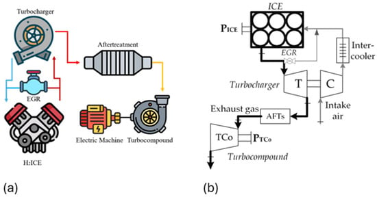
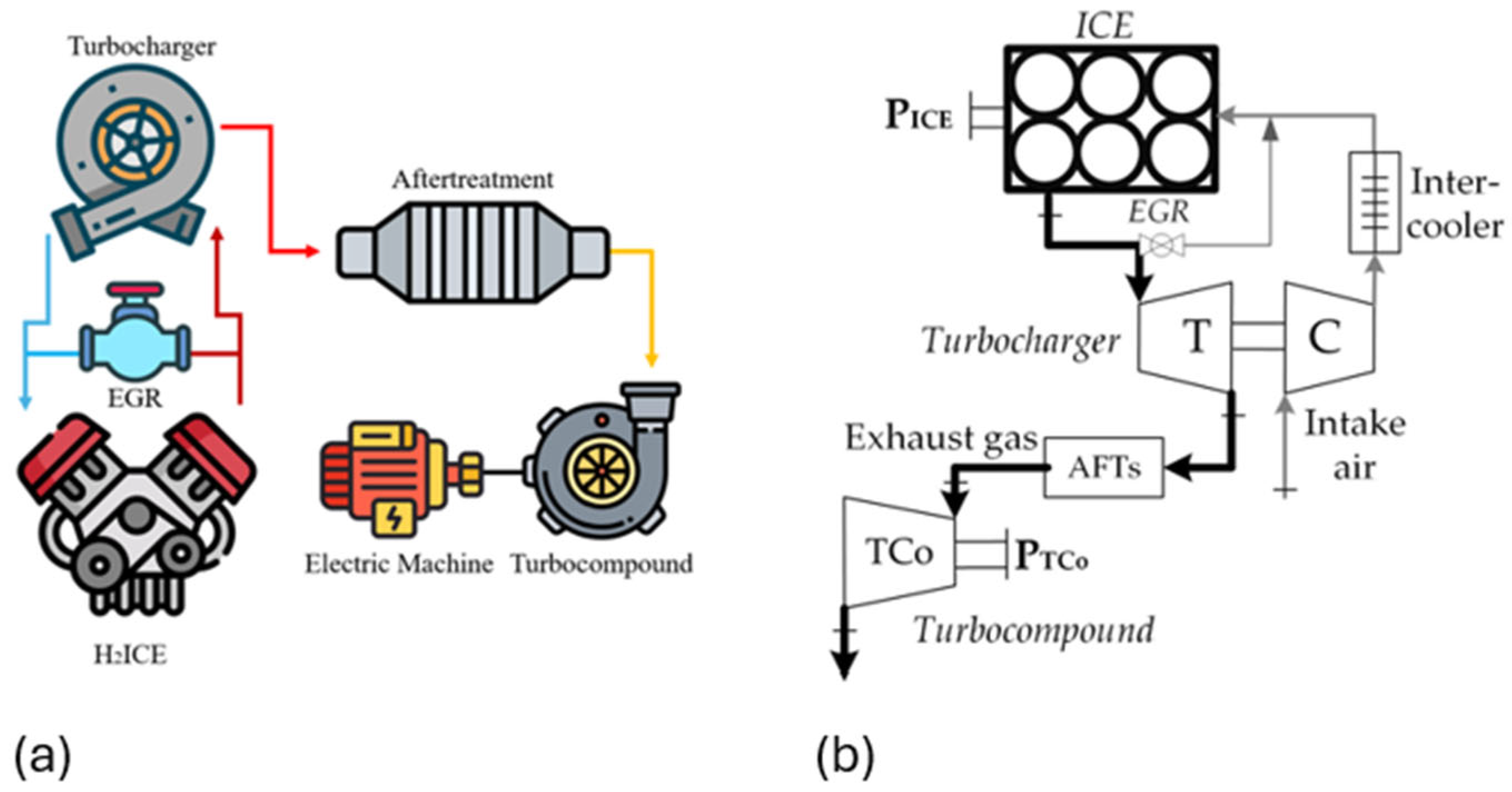
Figure 1.
Graphical (a) and flux (b) layout scheme.
The engine is a 3.0 L V6 configuration, fueled with double PFI, equipped with a single stage VGT turbocharger (with a charge air cooler), and integrates a high-pressure EGR circuit. Furthermore, the engine is equipped with an integrated throttle body to allow operating the engine at low load without resulting in too much lean mixture. The engine model features a dedicated predictive combustion model previously calibrated in the range of λ equal to 2 up to 2.7 [46]. The frictions are modelled following a calibrated Chen–Flynn model as a function of engine speed and maximum in-cylinder pressure. The engine load can be directly controlled by means of a proper controller implemented in the 1-D GT Power model that allows setting the correct position of the VGT, throttle angle, and hydrogen-injected mass to deliver the requested Brake Mean Effective Pressure (BMEP) at the desired air-to-fuel ratio. Moreover, even a high-pressure EGR system has been considered (in this case, a dedicated controller has been developed to meet the desired target EGR rate by controlling the orifice diameter of the EGR valve). To maximize the benefits of cooled EGR in mitigating NOx and reducing knock tendency, a dedicated EGR cooler is placed before the EGR mass is recirculated into the air intake. After the expansion in the turbine of the turbocharger, the exhaust gases are routed through an SCR system to reduce NOx emissions and finally pass through an additional radial turbine (TCo system [45]), where energy is recovered from the exhaust gases to drive an electric generator, enhancing overall system efficiency by converting residual exhaust enthalpy into usable power. The reference layout for the energy recovery is reported in Figure 1. The engine used, before the inclusion of the turbocompound, had a VGT and the aftertreatment devices were placed downstream the supercharging turbine. The overall aftertreatment devices (AFTs), including SCR, were inserted immediately downstream of the turbocharger, as usually happens, in order to ensure that their operation was guaranteed effectively in any engine condition. Above all, it was preferred to keep them upstream the turbocompound to keep higher exhaust temperatures, especially at low engine power, when the temperature of the exhaust gases is low, avoiding the possible performance reduction in the AFTs. In the Gt Suite® v2022 model, they have been represented in a lumped way, in order to compute the pressure losses and the effect they produce, especially on the TCo, which is affected by operating conditions characterized by low expansion ratios (maximum equal to 1.5 in the engine points close to those of maximum power) if compared with those of the turbocharging turbine.
AFTs’ pressure drops have been estimated to be less than 35 mbar at the highest gas mass flow rates (200 g/s), which can be considered negligible in the TCo final performance and for the engine backpressure side effect. The TCo is designed with a map-based approach [45], where the relevant characteristic quantities are used (exhaust mass flow rate, expansion pressure ratio, revolution speed, and turbine efficiency ) to characterize its behavior. It has been derived from the existing turbocharger. Once the exhaust mass flow rate , pressure , and temperature are known, the expansion ratio can be calculated and the revolution speed and efficiency are estimated (Equation (1)).
Hence, the mechanical power recovered is evaluated according to Equation (2), where the mechanical efficiency of the turbocompound is evaluated considering the mechanical losses that occur in the bearings and seals. It also depends on the lubrication conditions: for the tests performed, a 5W-30 oil was chosen, obviously operating at the same operating temperature of about 90 °C as the engine oil. It has been seen that the mechanical efficiency relating to the WHR system alone varies between 94.5 and 98.5%, and more specifically tends to decrease with the increase in the power produced by the turbocompound itself due to the higher rotation speed, which has a negative influence [47].
An electric generator could be coupled and integrated into the TCo, thus it rotates at the same rotational speed of the TCo. Since very high rotational speeds are reached with the gases passing through the radial recovery turbine, even higher than 100 krpm, the electric machine must be able to sustain such speeds [48], and it should convert the mechanical power into DC electrical form, in order to be stored or used in a vehicle.
The model has been exploited to generate a comprehensive dataset (summarized in Table 2) that serves as a reference for calibrating engine control [40] and assessing the potential benefits of the TCo system in terms of efficiency and power output.
Table 2.
Engine sweep tests.
The database has been constructed by systematically varying key parameters: engine speed, BMEP, dilution (as the air-to-hydrogen normalized ratio, λ, and the percentage of EGR), center of combustion where 50% of the energy is released (CA50), and TCo speed. The investigated points allow for completely spanning the entire operative field of the system (engine coupled with TCo).
The next step consists in the optimization of the working points: for any given engine speed and BMEP, the optimal configuration (defined as the combination of TCo speed, CA50, λ, and EGR) has been identified following a dedicated optimization procedure, allowing to properly calibrate an already developed control strategy for H2ICEs [40]. Such control strategy (schematized in Figure 2) allows delivering the requested torque at the given engine speed by means of a CA50 torque-based controller. It takes as inputs the engine speed and requested engine load. Then, the requested load is converted into an equivalent corrected hydrogen mass. The fuel is then saturated between maximum and minimum values considering the actual intake air and lambda limits (to avoid knocking/backfire and misfire). Furthermore, the controller being CA50-based, targets optimal CA50 as a function of engine Operating Points (OPs) and λ. Moreover, protection strategies for knocking and excessive combustion pressures are integrated as well, relying on indicated feedback quantities (i.e., knock index and in-cylinder maximum pressure). Finally, VGT and THR positions are set by dedicated maps as well as EGR valve diameter.
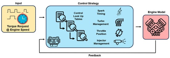
Figure 2.
Schematic of engine control system.
2.2. Combustion-Turbocompound Optimized Management
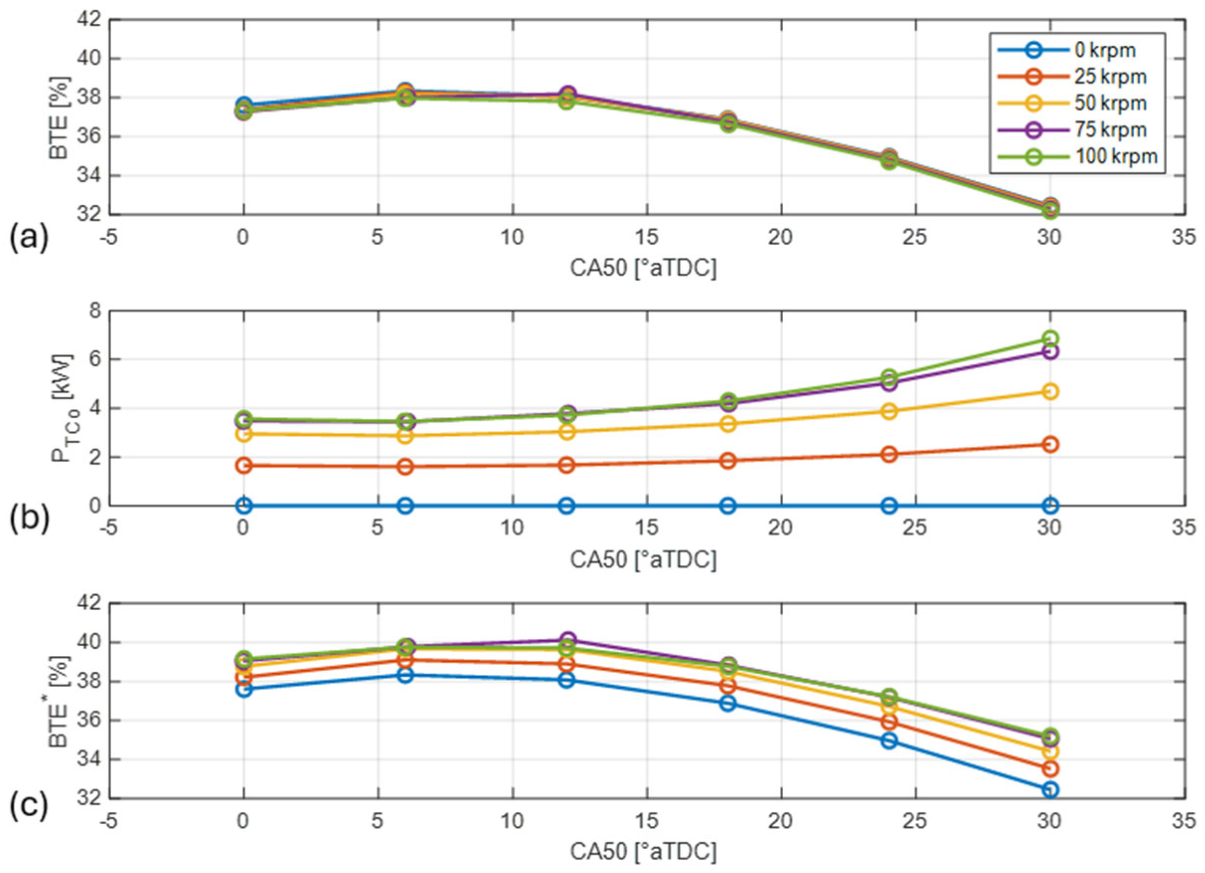
The TCo system is directly coupled with an electric machine, allowing the speed of the TCo to be precisely controlled independently from the OP of the H2ICE, enabling a more flexible and dynamic control strategy, as the electric machine can operate at varying speeds independent of the engine’s rotational speed and load. Consequently, the same control structure previously presented (the control strategy can manage the engine both in conventional and hybrid configurations, as it is based on a torque request) [40] for optimizing powertrain efficiency can be directly applied, but a new approach, aimed at identifying the optimal OPs, has to be developed. For a fixed engine speed and load, the optimal OP must be carefully evaluated by considering the interaction between combustion characteristics and the PTCo. For simplicity, as mentioned in the previous paragraph, the tests were conducted at constant BMEP, thus the PTCo is considered as additional available power. Alternatively, the tests could have been carried out at constant total power (H2ICE power summed to PTCo), but this would have required the development of dedicated methodologies, as the PTCo varies with combustion conditions [28]. To describe the procedure for the identification of the optimal engine working point (for given engine speed and BMEP), in Figure 3, sweeps of CA50 and TCo speed are performed for fixed engine speed, load, and dilution (2000 rpm, BMEP 10 bar, λ 2, EGR 0%). In Figure 3a, the Brake Thermal Efficiency (BTE) is plotted against the CA50, shaping the well-known umbrella curve, which could be affected by different λ values (since it affects the ignition delay) [49]. As it is possible to see, small differences can be identified by varying the speed of the TCo (these are related to the different permeabilities of the exhaust line as a function of the speed of the TCo, especially when the speed of the TCo is maintained at 100 krpm, and the curve moves toward lower BTEs). This is mainly related to the design criteria adopted for the TCo [45] and the mitigation of the engine backpressure effect thanks to the control strategy adopted. In fact, given the definition of BTE (defined in Equation (3), where represents the hydrogen mass flow, PICE represents the power provided by the H2ICE, and LHV represents the Lower Heating Value of the hydrogen), there is no direct effect of the TCo on engine efficiency.
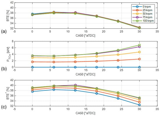
Figure 3.
Visualization of TCo rotational speed’s effect on BTE (a), PTCo (b), and BTE* (c), as a function of the CA50° value.
However, BTE decreases as CA50 is retarded (starting from the optimal CA50, i.e., 6 °aTDC). In fact, owing to lower conversion efficiency, needs to be increased to maintain the same level of power (boost pressure increases too to maintain the fixed λ value). Conversely, analyzing Figure 3b where the PTCo is reported, it is possible to identify a clear effect of both TCo speed and CA50 on the extracted PTCo. In fact, as the speed of the TCo increases, the extracted power for a fixed position of the CA50 increases as well [28]. Given the speed of the TCo, retarding the CA50 leads to a higher PTCo level, owing to the higher energy content in the exhaust gases. However, simply maximizing the PTCo could lead to overall lower efficiency; as the combustion is retarded, the PTCo increases but the engine BTE deteriorates. For this reason, a corrected BTE (BTE*) has been introduced, defined in Equation (4), allowing us to consider both power contributions.
The definition of the BTE* must be tailored as a function of the hybrid powertrain layout. For series layouts, the optimization should keep into account the electric power produced by the H2ICE (i.e., considering the efficiency of the generator), while for applications where the H2ICE is directly coupled with the wheels, the mechanical power should be considered (in these layouts, the PTCo value is the mechanical one—according to Equation (4), in order to be compared to the engine brake power, but it can be used both as electric power and to drive electric or mechanic auxiliaries). Figure 3c reports the trend of BTE* as a function of CA50 and TCo speed. As it is possible to see, with respect to the optimal BTE, when only the engine is considered (38% with a CA50 equal to 6 °aTDC), the optimized working point allows achieving more than 40% (with a slightly more retarded CA50) at a speed equal to 75 krpm, which corresponds to an efficiency gain of 5.3%.
3. Results
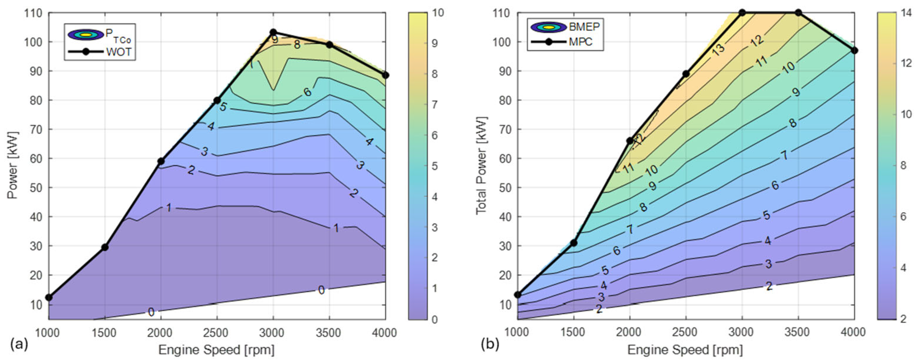
The optimization procedure on BTE* (the identification of the optimal working conditions for each engine point as reported in Section 2.2) demonstrated a significant peak PTCo. As visible in Figure 4a where the PTCo is displayed as a function of engine speed and power, for a given power level, the PTCo is almost constant between 1000 and 3500 rpm, while in the range of 3500–4000 rpm, the PTCo is lower. This is related to the fact that, for a given engine power, the higher engine speed (which also means higher friction losses) results in a lower BMEP, and thus lower potential residual energy in the exhaust gases. A peak power of 9 kW can be recovered from the TCo, meaning that the same power level can be achieved by the system (i.e., considering both engine and TCo) with a lower engine BMEP for any given engine speed, as visible in Figure 4b, where the equivalent BMEP corresponding to every power level is reported together with the Maximum Power Curve (MPC, which represents the total available maximum power available from the system).

Figure 4.
Recovered PTCo as a function of engine speed and power (a) and engine BMEP as a function of the system’s total power and engine speed (b).
For a given requested power profile (in hybrid series), the optimal engine OP should be identified with the purpose of minimizing the integral performance index (J) [22] defined in Equation (5), where tf and ti represent the finish and start time.
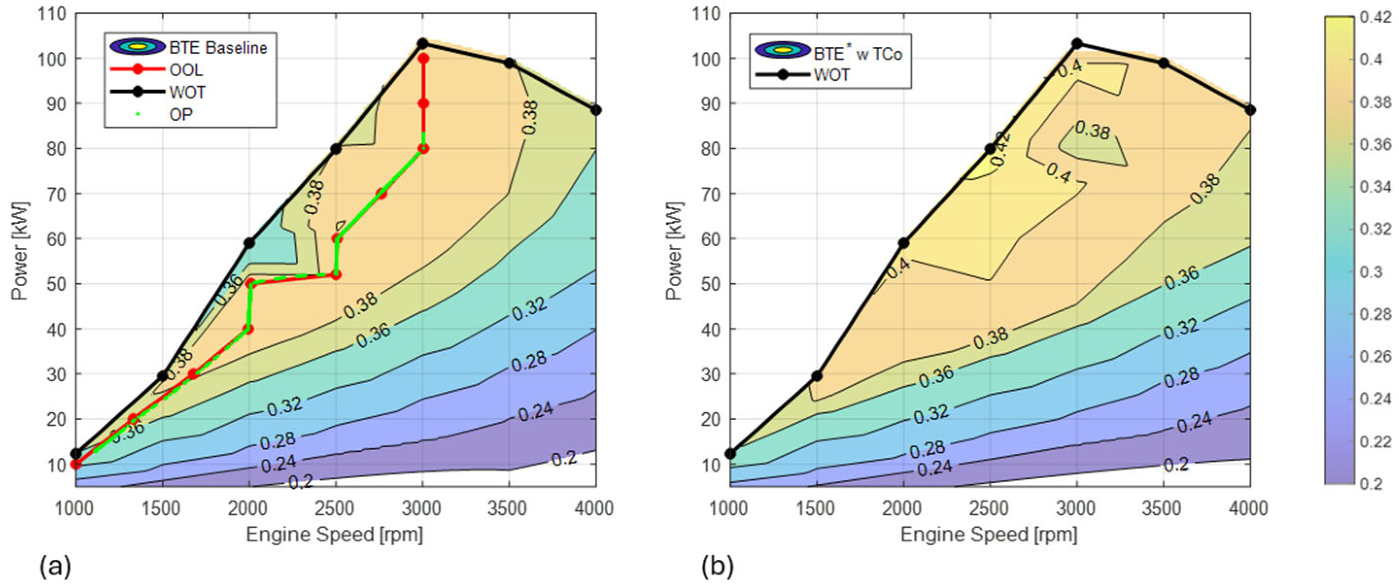
Considering this extra-power contribution of the TCo, the final power request to the H2ICE can be lowered, leading to lower hydrogen consumption. In Figure 5a, the BTE of the baseline engine configuration (i.e., without the TCo system) is shown, representing the baseline performance of the internal combustion engine alone. Furthermore, the Wide Open Throttle (WOT, i.e., the maximum power curve of the engine) is represented as well as the Optimal Operating Line (OOL, i.e., the line where the efficiency is maximized for each power level). The OOL has been identified considering for each level of power the working point that maximizes the product between engine efficiency (or powertrain for the cases where the TCo is installed) and the generator efficiency [7]. In Figure 5b, the BTE* is represented taking into account the contribution of the TCo as a function of PICE. As visible from Figure 5b, for each power level, the highest BTE* is achieved almost everywhere on the WOT curve.
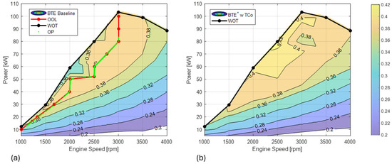
Figure 5.
Engine baseline BTE (a), BTE* with installed TCo after the optimization (b).
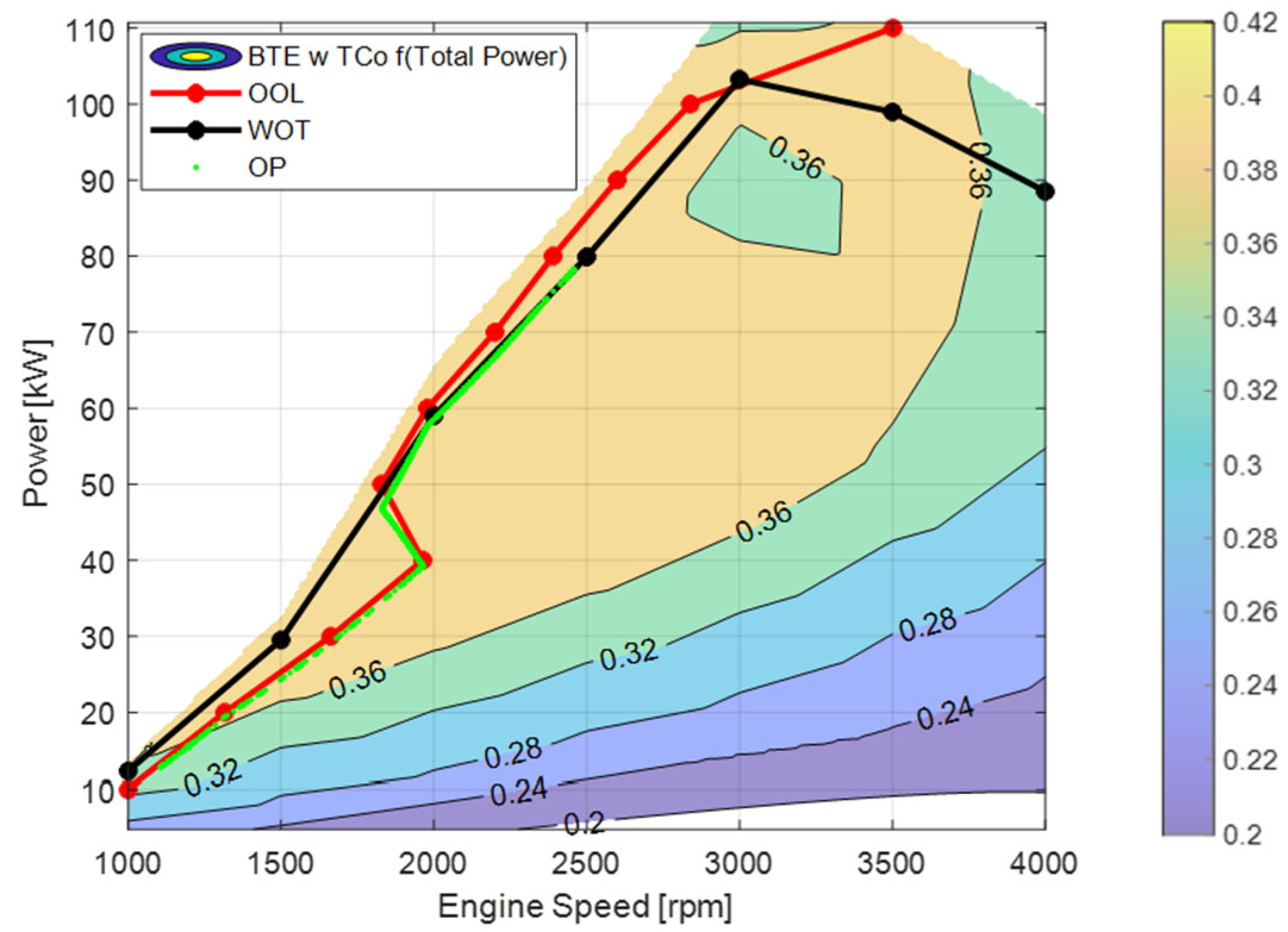
The optimization procedure shows that the TCo installation is favorable except for engine speed greater than 3500 rpm and power lower than 20 kW. This is because the friction losses are maximized at those conditions and the energy in the exhaust gases is limited; therefore, the gain in the TCo is not enough to counterbalance the losses in the combustion due to the higher backpressure. However, these operating conditions are almost never experienced by the engine. As a matter of fact, for the hybrid layout, these are suboptimal points that are never reached, while for a conventional drivetrain, it is unlikely to experience a high engine speed (close to the maximum level) and extremely low power levels. Figure 6 illustrates the BTE of the engine after the optimization, where the engine is now equipped with the TCo system as a function of the system’s total available power (PICE + PTCo); for this reason, the peak power reaches 110 kW. The OOL of the system in this case identifies the optimal OP considering the contribution of the TCo; thus, it can overcome the WOT line.
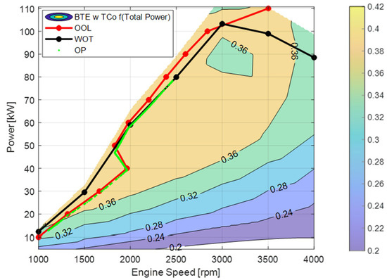
Figure 6.
BTE considering the power recovered by the TCo.
Under the WOT line for a given engine point, the BTE of the engine is generally lower with respect to the baseline due to the optimization procedure on CA50, which slightly decreases the BTE to enhance the BTE*. To assess the potential of the new layout, the two engine configurations have been assessed on the same reference Braunschweig homologation cycle by imposing the power request previously determined following Pontryagin Minimum Principle (PMP) energy management optimization [7,22]. For the baseline configuration (Figure 5a), the requested power coincides with the power provided by the engine, while for the layout equipped with the TCo, it coincides with sum of PICE and PTCo. The OPs that correspond to the requested power levels are the green dots in Figure 5a and Figure 6. As it is possible to see, the peak requested power in the baseline configuration is slightly higher than 80 kW. Conversely, for the same power request, in the new layout, the engine needs to provide a lower power equal to the difference between the requested and the available power from the TCo. Given the power requested, the OOL identifies the optimal engine speed. Knowing the total power and engine speed, the equivalent requested BMEP can be calculated (Figure 4b), allowing us to identify the engine OPs (Figure 6, where the peak power, for instance, is slightly lower than 80 kW). Following the presented approach, the corresponding hydrogen consumption has been estimated and compared with the baseline one. A consumption reduction equal to 6.8% has been achieved thanks to the PTCo. This gain in fuel efficiency could be particularly interesting for commercial and collective transport application as the lower consumption could allow reducing the hydrogen tank size (for fixed autonomy) and increasing the maximum payload.
4. Conclusions
In the present work, the potential of bottoming a TCo to an H2ICE as a suitable technology to optimize fuel efficiency in hybrid powertrains has been assessed. Firstly, a reference dataset of a 0-D H2ICE equipped with TCo has been generated from a 1-D GT Power engine model. For a fixed engine load and speed, the optimal working points have been identified through a dedicated optimization technique implemented by means of a corrected Brake Thermal Efficiency to harmoniously maximize the overall efficiency of the engine and TCo. Then, the Optimal Operating Line (OOL) of the engine coupled with the TCo has been identified as a suitable application in a series hybrid configuration. The optimization allows increasing by 9% the peak power (9 kW) with respect to the baseline configuration. For fixed total power requests, the optimal engine speed can be identified on the OOL and the equivalent engine load calculated. The recovered power allows reducing the engine load for a given total power request, leading to a 6.8% reduction in the total hydrogen consumption on a reference homologation cycle.
Future development would focus on further energy recovery, assessing the potential of installing an Organic Rankine Cycle bottomed to the TCo.
Author Contributions
Conceptualization, P.P.B., E.C., V.R. and D.D.B.; methodology, P.P.B., F.D.P., E.C., V.R., D.D.B. and V.R.; software, P.P.B., F.D.P. and D.D.B.; validation, P.P.B., F.D.P., E.C. and D.D.B.; formal analysis, E.C., V.R. and D.D.B.; investigation, P.P.B., F.D.P., E.C., D.D.B. and V.R.; resources, E.C., V.R. and D.D.B.; data curation, P.P.B. and F.D.P.; writing—original draft preparation, P.P.B. and V.R.; writing—review and editing, E.C. and D.D.B.; visualization, P.P.B., V.R. and E.C.; supervision, E.C., V.R., D.D.B. and R.C.; project administration, E.C., R.C., D.D.B. and V.R.; funding acquisition, E.C., V.R., D.D.B. and R.C. All authors have read and agreed to the published version of the manuscript.
Funding
This research was funded by Ministero dell’Istruzione, dell’Università e della Ricerca (MIUR), grant number 2020R92Y3Z.
Data Availability Statement
The data presented in this study are partially available on request from the corresponding author.
Conflicts of Interest
The authors declare no conflicts of interest.
Abbreviations
The following abbreviations are used in this manuscript:
| AFT | Aftertreatment device |
| aTDC | After Top Dead Center |
| BEV | Battery Electric Vehicle |
| BMEP | Brake Mean Effective Pressure |
| BSFC | Brake Specific Fuel Consumption |
| BTE | Brake Thermal Efficiency |
| BTE* | Corrected BTE |
| CA50 | Crank Angle where 50% of Energy is Released |
| EGR | Exhaust Gas Recirculation |
| FC | Fuel Cell |
| H2ICE | Hydrogen Internal Combustion Engine |
| J | Integral Performance Index |
| LHV | Lower Heating Value |
| MPC | Maximum Power Curve |
| OOL | Optimal Operating Line |
| OP | Operative Point |
| ORC | Organic Rankine Cycle |
| PEM-FC | Proton Exchange Membrane Fuel Cell |
| pexh | Exhaust Pressure |
| PFI | Port Fuel Injection |
| PICE | Power of Internal Combustion Engine |
| PMP | Pontryagin Minimum Principle |
| PTCo | Power of the Turbocompound |
| SCR | Selective Catalyst Reduction |
| Texh | Exhaust Temperature |
| TCo | Turbocompound |
| VGT | Variable Geometry Turbine |
| WHR | Waste Heat Recovery |
| WOT | Wide Opened Throttle |
| λ | Air-to-Hydrogen Normalized Ratio |
| Hydrogen Mass Flow Rate | |
| Exhaust Mass Flow Rate | |
| ηTCO | Turbocompound Efficiency |
References
- European Green Deal—Consilium. Available online: https://www.consilium.europa.eu/en/policies/green-deal/ (accessed on 12 February 2024).
- Transport and Mobility. Available online: https://www.eea.europa.eu/en/topics/in-depth/transport-and-mobility (accessed on 7 November 2024).
- Manzetti, S.; Mariasiu, F. Electric vehicle battery technologies: From present state to future systems. Renew. Sustain. Energy Rev. 2015, 51, 1004–1012. [Google Scholar] [CrossRef]
- Giuliano, G.; Dessouky, M.; Dexter, S.; Fang, J.; Hu, S.; Miller, M. Heavy-duty trucks: The challenge of getting to zero. Transp. Res. Part D Transp. Environ. 2021, 93, 102742. [Google Scholar] [CrossRef]
- Sadeq, A. Alternative Fuels for Sustainable Combustion. 2024. Available online: https://www.researchgate.net/publication/382547111_Alternative_Fuels_for_Sustainable_Combustion (accessed on 10 January 2025).
- Ahluwalia, R.K.; Wang, X. Fuel cell systems for transportation: Status and trends. J. Power Sources 2008, 177, 167–176. [Google Scholar] [CrossRef]
- Arsie, I.; Battistoni, M.; Brancaleoni, P.P.; Cipollone, R.; Corti, E.; Di Battista, D.; Millo, F.; Occhicone, A.; Paradisi, B.P.; Rolando, L.; et al. A New Generation of Hydrogen-Fueled Hybrid Propulsion Systems for the Urban Mobility of the Future. Energies 2023, 17, 34. [Google Scholar] [CrossRef]
- Boretti, A. Hydrogen internal combustion engines to 2030. Int. J. Hydrogen Energy 2020, 45, 23692–23703. [Google Scholar] [CrossRef]
- Chai, W.S.; Bao, Y.; Jin, P.; Tang, G.; Zhou, L. A review on ammonia, ammonia-hydrogen and ammonia-methane fuels. Renew. Sustain. Energy Rev. 2021, 147, 111254. [Google Scholar] [CrossRef]
- Zuo, Q.; Yang, D.; Shen, Z.; Chen, W.; Lu, C.; Chen, L.; Lei, S. Effect of premixed ratio on combustion and emission characteristics in a spark ignition engine with hydrogen-ammonia direct injection. Fuel 2025, 393, 135051. [Google Scholar] [CrossRef]
- Acar, C.; Dincer, I. The potential role of hydrogen as a sustainable transportation fuel to combat global warming. Int. J. Hydrogen Energy 2020, 45, 3396–3406. [Google Scholar] [CrossRef]
- What are eFuels?—eFuel Alliance. Available online: https://www.efuel-alliance.eu/efuels/what-are-efuels (accessed on 1 July 2024).
- Brancaleoni, P.P.; Ferretti, A.N.D.; Corti, E.; Ravaglioli, V.; Moro, D. Next-Gen Italian Urban Mobility: Emissions LCA and TCO Prospective for Innovative Transportation Solutions’, SAE International, Warrendale, PA, SAE Technical Paper 2025-01–8593, April 2025. Available online: https://www.sae.org/publications/technical-papers/content/2025-01-8593/ (accessed on 24 March 2025).
- Brancaleoni, P.P.; Ferretti, A.N.D.; Corti, E.; Ravaglioli, V.; Moro, D. Lifecycle CO2 analysis for urban emission reduction of hydrogen-fuelled and battery electric buses in the European Union current and future energetic scenarios. Int. J. Hydrogen Energy 2025, 123, 335–353. [Google Scholar] [CrossRef]
- Bar-On, I.; Kirchain, R.; Roth, R. Technical cost analysis for PEM fuel cells. J. Power Sources 2002, 109, 71–75. [Google Scholar] [CrossRef]
- Barbir, F. PEM Fuel Cells: Theory and Practice, 2nd ed.; Elsevier: Amsterdam, The Netherlands; Academic Press: Boston, MA, USA, 2013. [Google Scholar]
- Aggarwal, A.; Yadav, S.; Singh, K.; Verma, A.S.; Chhabra, S. Study of utilization of hydrogen as fuel in internal combustion engine. Mater. Today: Proc. 2022, 64, 1211–1216. [Google Scholar] [CrossRef]
- Shinde, B.J.; Karunamurthy, K. Recent progress in hydrogen fuelled internal combustion engine (H2ICE)—A comprehensive outlook. Mater. Today Proc. 2021, 51, 1568–1579. [Google Scholar] [CrossRef]
- Di Vece, G.; Di Nunno, D.; Bilancia, M.; Verdino, V. Development of a Total Cost of Ownership Model to Compare BEVs, FCEVs and Diesel Powertrains on Bus Applications. In Proceedings of the CO2 Reduction for Transportation Systems Conference, SAE Technical Paper 2022-37-0030, Turin, Italy, 21–22 June 2022. [Google Scholar] [CrossRef]
- Raser, B.A. Total Cost of Ownership (TCO) Analysis for Heavy Duty Hydrogen Fueled Powertrains; Westport Fuel Systems: Vancouver, BC, Canada; AVL List GmbH: Graz, Austria, 2021. [Google Scholar]
- Brancaleoni, P.P.; Corti, E.; Ravaglioli, V.; Moro, D.; Silvagni, G.; Brusa, A.; Cavina, N.; Ponti, F. Performance Evaluation of Hydrogen-Powered Internal Combustion Engine City Bus for the Urban Mobility of Bologna, Italy. J. Phys. Conf. Ser. 2024, 2893, 012068. [Google Scholar] [CrossRef]
- Onori, S.; Serrao, L.; Rizzoni, G. Hybrid Electric Vehicles; Springer: London, UK, 2016. [Google Scholar] [CrossRef]
- Analysis of Energy Conversion Efficiency in Parallel and Series Hybrid Powertrains. Available online: https://ieeexplore.ieee.org/abstract/document/4356917 (accessed on 18 June 2024).
- Babayev, R.; Im, H.G.; Andersson, A.; Johansson, B. Hydrogen double compression-expansion engine (H2DCEE): A sustainable internal combustion engine with 60%+ brake thermal efficiency potential at 45 bar BMEP. Energy Convers. Manag. 2022, 264, 115698. [Google Scholar] [CrossRef]
- Boretti, A. High-efficiency internal combustion engine for hybrid hydrogen-electric locomotives. Int. J. Hydrogen Energy 2022, 48, 1596–1601. [Google Scholar] [CrossRef]
- Overview of Hydrogen Internal Combustion Engine (H2ICE) Technologies. Available online: https://hydrogen.energy.gov (accessed on 20 March 2025).
- Hamada, A.T.; Orhan, M.F. An overview of regenerative braking systems. J. Energy Storage 2022, 52, 105033. [Google Scholar] [CrossRef]
- Aghaali, H.; Ångström, H.-E. A review of turbocompounding as a waste heat recovery system for internal combustion engines. Renew. Sustain. Energy Rev. 2015, 49, 813–824. [Google Scholar] [CrossRef]
- Kozak, D.; Mazuro, P. Review of Small Gas Turbine Engines and Their Adaptation for Automotive Waste Heat Recovery Systems. Int. J. Turbomach. Propuls. Power 2020, 5, 8. [Google Scholar] [CrossRef]
- Pipitone, E.; Caltabellotta, S. Efficiency Advantages of the Separated Electric Compound Propulsion System for CNG Hybrid Vehicles. Energies 2021, 14, 8481. [Google Scholar] [CrossRef]
- Kruiswyk, R. The role of turbocompound in the era of emissions reduction. In Proceedings of the 10th International Conference on Turbochargers and Turbocharging, London, UK, 15–16 May 2012; IMechE, Ed.; Woodhead Publishing: London, UK, 2012; pp. 269–280. [Google Scholar] [CrossRef]
- Lu, P.; Brace, C.; Hu, B. Explore and Extend the Effectiveness of Turbo-Compounding in a 2.0 Litres Gasoline Engine (Second Report: Fuel Economy under Part Load Condition, Transient Performance and Effect of Pressure Ratio). In Proceedings of the SAE 2016 World Congress and Exhibition, SAE International, Detroit, MI, USA, 5 April 2016. [Google Scholar] [CrossRef]
- Joshi, S.; Dahodwala, M.; Koehler, E.W.; Franke, M.; Tomazic, D.; Naber, J. Novel Approach to Integration of Turbocompounding, Electrification and Supercharging Through Use of Planetary Gear System. In Proceedings of the SAE International, Warrendale, PA, USA, 3 April 2018. SAE Technical Paper 2018-01–0887.. [Google Scholar] [CrossRef]
- Katsanos, C.; Hountalas, D.; Zannis, T. Simulation of a heavy-duty diesel engine with electrical turbocompounding system using operating charts for turbocharger components and power turbine. Energy Convers. Manag. 2013, 76, 712–724. [Google Scholar] [CrossRef]
- Leng, L.; Cheng, J.; Shi, L.; Deng, K. Thermodynamic analysis on the effect of altitude on the exhaust energy recovery of electric turbocompound engines. Proc. Inst. Mech. Eng. Part D J. Automob. Eng. 2024, 239, 535–547. [Google Scholar] [CrossRef]
- Ma, Z.; Zhang, K.; Xiang, H.; Gu, J.; Yang, M.; Deng, K. Experimental study on influence of high exhaust backpressure on diesel engine performance via energy and exergy analysis. Energy 2022, 263, 125788. [Google Scholar] [CrossRef]
- Effects of an ORC Based Heat Recovery System on the Performances of a Diesel Engine—Technical Paper. Available online: https://saemobilus.sae.org/papers/effects-orc-based-heat-recovery-system-performances-a-diesel-engine-2015-01-1608#citation (accessed on 16 April 2025).
- Carcasci, C.; Cheli, L.; Lubello, P.; Winchler, L. Off-Design Performances of an Organic Rankine Cycle for Waste Heat Recovery from Gas Turbines. Energies 2020, 13, 1105. [Google Scholar] [CrossRef]
- Wang, S.; Yuan, Z.; Yu, N. Off-design condition optimization of organic Rankine cycle based on genetic algorithm. Energy Built Environ. 2024, 5, 665–682. [Google Scholar] [CrossRef]
- Brancaleoni, P.P.; Corti, E.; Ravaglioli, V.; Moro, D.; Silvagni, G. Innovative torque-based control strategy for hydrogen internal combustion engine. Int. J. Hydrogen Energy 2024, 73, 203–220. [Google Scholar] [CrossRef]
- Heffel, J. NOx emission reduction in a hydrogen fueled internal combustion engine at 3000 rpm using exhaust gas recirculation. Int. J. Hydrogen Energy 2003, 28, 1285–1292. [Google Scholar] [CrossRef]
- Saravanan, N.; Nagarajan, G. An insight on hydrogen fuel injection techniques with SCR system for NOX reduction in a hydrogen–diesel dual fuel engine. Int. J. Hydrogen Energy 2009, 34, 9019–9032. [Google Scholar] [CrossRef]
- Fayaz, H.; Saidur, R.; Razali, N.; Anuar, F.; Saleman, A.; Islam, M. An overview of hydrogen as a vehicle fuel. Renew. Sustain. Energy Rev. 2012, 16, 5511–5528. [Google Scholar] [CrossRef]
- Cheng, Q.; Zhang, R.; Shi, Z.; Lin, J. Review of common hydrogen storage tanks and current manufacturing methods for aluminium alloy tank liners. Int. J. Light. Mater. Manuf. 2024, 7, 269–284. [Google Scholar] [CrossRef]
- Di Battista, D.; Di Bartolomeo, M.; Di Prospero, F.; Di Diomede, D.; Carapellucci, R.; Cipollone, R. Turbocompound energy recovery option on a turbocharged diesel engine. J. Phys. Conf. Ser. 2023, 2648, 012078. [Google Scholar] [CrossRef]
- Millo, F.; Piano, A.; Rolando, L.; Accurso, F.; Gullino, F.; Roggio, S.; Bianco, A.; Pesce, F.; Vassallo, A.; Rossi, R.; et al. Synergetic Application of Zero-, One-, and Three-Dimensional Computational Fluid Dynamics Approaches for Hydrogen-Fuelled Spark Ignition Engine Simulation. SAE Int. J. Engines 2021, 15, 561–580. [Google Scholar] [CrossRef]
- Harris, T.A.; Kotzalas, M.N. Advanced Concepts of Bearing Technology: Rolling Bearing Analysis; CRC Press: Boca Raton, FL, USA, 2006. [Google Scholar]
- Rosset, K.; Pajot, O.; Schiffmann, J. Experimental Investigation of a Small-Scale Organic Rankine Cycle Turbo-Generator Supported on Gas-Lubricated Bearings. J. Eng. Gas Turbines Power 2021, 143, 051015. [Google Scholar] [CrossRef]
- Wang, Y.; Xu, Z.; Zhang, C.; Liu, L. Combustion optimization of a hydrogen free-piston engine with high-energy ignition. Int. J. Hydrogen Energy 2023, 49, 483–494. [Google Scholar] [CrossRef]

Disclaimer/Publisher’s Note: The statements, opinions and data contained in all publications are solely those of the individual author(s) and contributor(s) and not of MDPI and/or the editor(s). MDPI and/or the editor(s) disclaim responsibility for any injury to people or property resulting from any ideas, methods, instructions or products referred to in the content. |
© 2025 by the authors. Licensee MDPI, Basel, Switzerland. This article is an open access article distributed under the terms and conditions of the Creative Commons Attribution (CC BY) license (https://creativecommons.org/licenses/by/4.0/).