
A Review of Seasonal Energy Storage for Net-Zero Industrial Heat: Thermal and Power-to-X Storage Including the Novel Concept of Renewable Metal Energy Carriers


Abstract
1. Introduction
- Long-term thermal energy storage (TES) technologies
- Power-to-X (P2X) technologies: These involve converting renewable energy into chemical energy stored in gases, liquids, or solids (e.g., hydrogen, synthetic fuels, and renewable metal energy carriers).
2. Key Performance Indicator
- Economic factors: A low cost of technology (material, container, space, maintenance, and lifetime), resulting in a low cost of storage, as well as a high degree of (storage) material availability;
- Performance factors: A high energy storage density and thus low space requirement, as well as high storage efficiency (i.e., low losses);
- Functional and technical suitability: Long-term stability, the capability of storing renewable energy over several months, chemical compatibility with the container and energy exchange loops, if applicable;
- Environmental sustainability: Low environmental impact for a normal use case, recyclability, and a closed-loop economy;
- Safety and risk mitigation: Low risks for humans and the environment (e.g., non-toxic, non-flammable, low risks at unforeseen events, environmentally “friendly” material, and processes) and moderate pressure regarding the storage medium.
2.1. Annual Cost of Heat Storage
2.2. Levelized Cost of P2X Storage
3. Thermal Energy Storage Solutions
3.1. Parameters of TES
- Capacity per unit volume: The energy stored per unit volume (kWh/m3) varies depending on the storage material, such as water, molten salts, or phase-change materials, each providing different energy densities.
- Temperature range (ΔT): The operating temperature range defines the energy storage capacity, for example, 40 to 90 °C.
- Heat transfer and associated losses: Heat is added or removed via exchangers or conduits, and minimizing the temperature difference during transfer reduces exergy losses.
- Temperature stratification and exergetic efficiency: Maintaining temperature layers in sensible heat storage improves efficiency of connected processes, whereas exergetic efficiency preserves temperature levels and ensures that stored energy is converted back into useful work.
- Power requirements: The energy required for heat injection or extraction, such as pumps or compressors, affects operational costs and efficiency.
- Structural elements: Storage systems use tanks, pits, or natural formations, with materials such as concrete or steel affecting durability and insulation.
- Thermal loss control: Insulation or covers can minimize energy losses, with advanced materials reducing the heat transfer to the surroundings.
- Cost: Initial installation costs and ongoing operational expenses, including material choices and energy requirements, determine the affordability of a system.
3.2. Types of TES
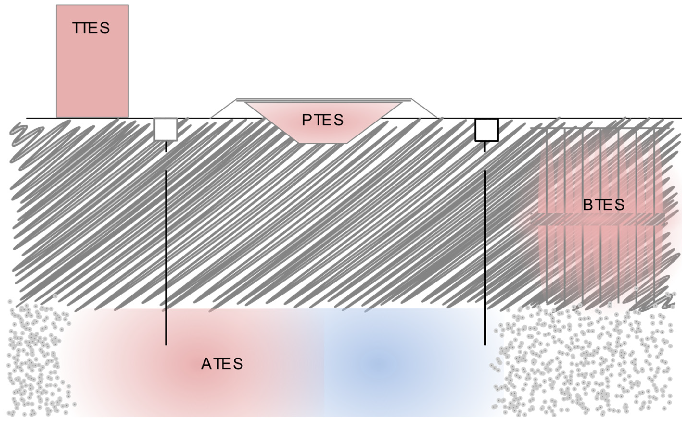
3.2.1. Sensible TES Systems
- Utilizing inexpensive and abundant materials such as water, soil, or gravel as storage media significantly lowers the costs of seasonal TES.
- No support structures bearing the weight of the storage medium must be built.
- In the case of BTES or ATES, Earth serves a dual purpose by both containing and providing support for the storage medium.
- The lid may float or rest on the storage medium and be supported by the storage medium. Hence, there is no need to construct a fixed static structure to support this lid.
- Floating insulated lids, which are often used in PTES with water, help seal the system and minimize heat loss.
- The storage volume is large enough or the temperature difference to the surrounding ground is low enough that the heat losses are low, even without technical insulation between the storage medium and the surrounding ground. Large storage volumes have a lower surface-area-to-volume ratio, which inherently minimizes heat loss. Additionally, if the temperature gradient between the storage medium and the surrounding ground is relatively small, the heat transfer is naturally limited, further reducing the energy losses.
3.2.2. Phase Change Energy Storage
3.2.3. Thermochemical or Sorption Storage
3.3. Integration of TES into Industrial Processes
4. Power-to-X Storage
4.1. Hydrogen
4.2. Methane
4.3. Methanol
4.4. Ammonia
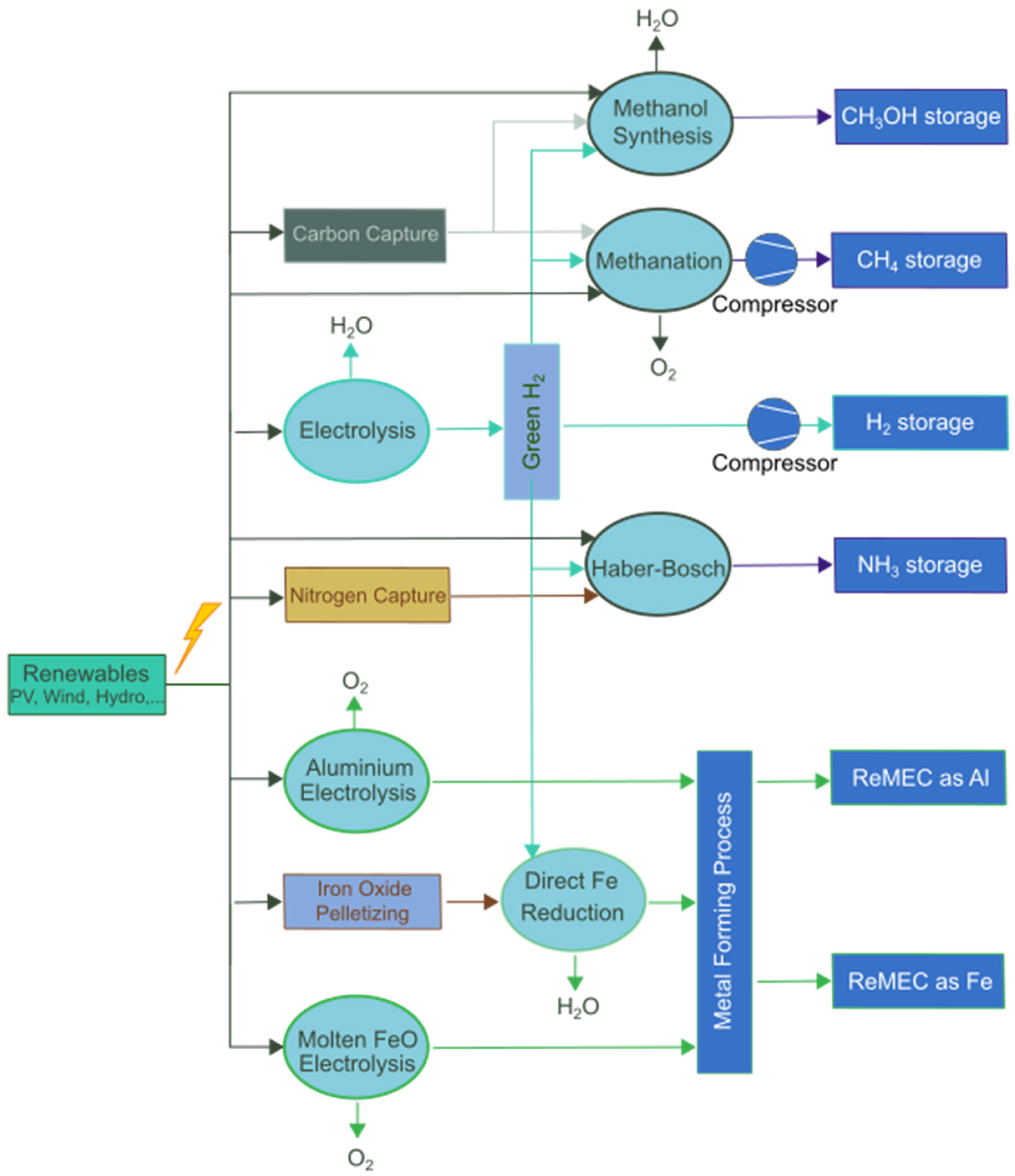
4.5. Renewable Metal Energy Carriers
5. Results
5.1. Thermal Energy Storage
5.1.1. Sensible Heat Storage
5.1.2. Latent Heat Storage
5.1.3. Sorption Heat Storage
5.2. Power-to-X Storage
5.2.1. Hydrogen, Methane, Methanol, and Ammonia
5.2.2. Renewable Metal Energy Carrier: Aluminum and Iron
6. Discussion
6.1. Thermal Energy Storage
6.2. Power-to-X Storage
6.3. Future of SES Adoption
Author Contributions
Funding
Data Availability Statement
Conflicts of Interest
Abbreviations
| ATES | Aquifer Thermal Energy Storage |
| BTES | Borehole Thermal Energy Storage |
| CHP | Combined Heat and Power |
| COP | Coefficient of Performance |
| CTES | Cavern Thermal Energy Storage |
| ECB | European Central Bank |
| ETS | Emission Trading System |
| GH2 | Gaseous Hydrogen |
| HTHP | High-Temperature Heat Pump |
| HT-TES | High-Temperature Thermal Energy Storage |
| IEA | International Energy Agency |
| KPI | Key Performance Indicator |
| ACOHS | Annual Cost of Heat Storage |
| LCOXS | Levelized Cost of Power-to-X Storage |
| LH2 | Liquid Hydrogen |
| LHV | Lower Heating Value |
| LT-TES | Lower-Temperature Thermal Energy Storage |
| P2X | Power-to-X |
| PCM | Phase Change Material |
| PTES | Pit Thermal Energy Storage |
| SES | Seasonal Energy Storage |
| TCP | Technology Collaboration Program |
| TES | Thermal Energy Storage |
| TTES | Tank Thermal Energy Storage |
| UTES | Underground Thermal Energy Storage |
Appendix A
Appendix A.1

| TES Type | TTES | UTES | PCM | Sorption | ||||||||
|---|---|---|---|---|---|---|---|---|---|---|---|---|
| Storage medium / UTES-type | H2O | SS | VO | BTES | PTES | CTES | ATES | ET | XT | S/G | NO | SG |
| Project-specific parameters | ||||||||||||
| Storage capacity, MWh | 2900 | 1950 | 1320 | 20,000 | 40,000 | 11,600 | 20,000 | 580 | 460 | 320 | 560 | 500 |
| Storage volume, m3 | 5 × 10⁴ | 5 × 10⁴ | 5 × 10⁴ | 5 × 10⁵ | 5 × 10⁵ | 3 × 10⁵ | 5 × 10⁵ | 4 × 10³ | 4 × 10³ | 4 × 10³ | 3× 10³ | 3 × 10³ |
| CAPEXstorage, million EUR | 6.0 | 6.2 | 10.5 | 5.7 | 15.0 | 15.0 | 5.0 | 106.5 | 110.4 | 124.3 | 9.3 | 7.2 |
| Discount rate, % | 5 | |||||||||||
| Utilization of usable storage capacity, % | 100 | 100 | 100 | 80 | 100 | 80 | 80 | 100 | 100 | 100 | 100 | 100 |
| SC per year | 1 | |||||||||||
| External parameters | ||||||||||||
| OPEXcharging, EUR/kWh thermal | 0 | |||||||||||
| Storage specific parameters | ||||||||||||
| SC Efficiency, % | 90 | 90 | 90 | 70 | 80 | 80 | 75 | 90 | 90 | 90 | 80 | 80 |
| OPEX, %CAPEX/y | 1 | 1 | 1 | 1 | 0.5 | 0.5 | 1 | 0.1 | 0.1 | 0.1 | 1 | 1 |
| Economic lifetime | 50 | 50 | 20 | 40 | 25 | 30 | 30 | 20 | 20 | 20 | 20 | 20 |
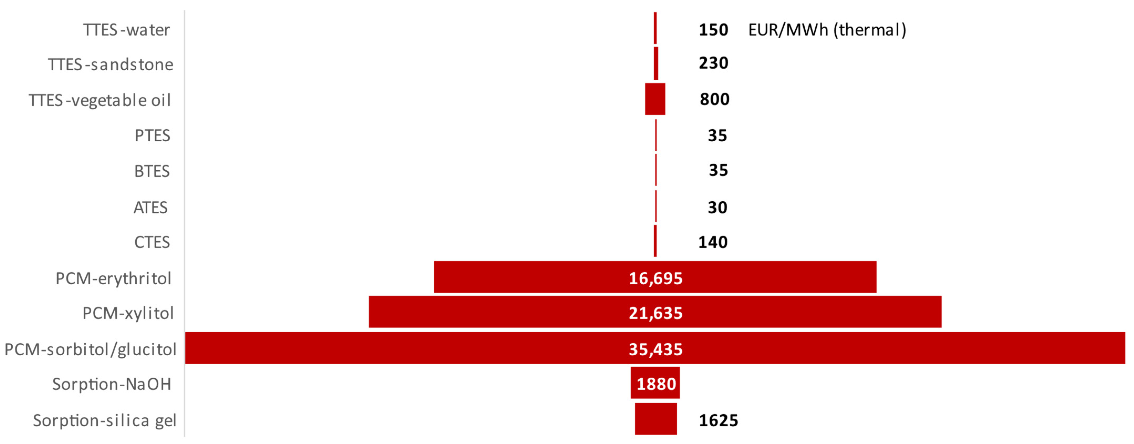
| LCOHS, EUR/MWh | 149 | 229 | 798 | 35 | 36 | 142 | 31 | 11,697 | 21,634 | 35,433 | 1880 | 1624 |
| References | [18,29] | [18,29,47] | [18,19] | [15,18,23,27] | [15,18,23] | [18,23] | [15,18,23] | [9,14,47] | [9,14] | [9,14] | [45,47] | |
Appendix A.2
| Storage Medium | Hydrogen | CH4 | CH3OH | NH3 | Al | Fe | ||||
|---|---|---|---|---|---|---|---|---|---|---|
| GH2 (500 bar) | cavern (70–150 bar) | LH2 | A | B | A | B | ||||
| Project-specific-parameters | ||||||||||
| Storage capacity, MWh | 4.0 × 101 | 9.0 × 10⁴ | 2.3 × 10⁴ | 1.8 × 10⁵ | 1.8 × 10⁵ | 2.0 × 10⁵ | 2.0 × 10⁵ | 1.9 × 10⁵ | ||
| Storage volume, m3 | 3 × 101 | 8 × 10⁵ | 1 × 10⁴ | 3 × 10⁴ | 3 × 10⁴ | 4 × 10⁴ | 4 × 10⁴ | 4 × 10⁴ | ||
| CAPEXstorage, million EUR | 0.6 | 18.0 | 18.9 | 3.0 | 1.0 | 14.0 | 14.0 | 15.2 | ||
| Discount rate, % | 5 | |||||||||
| Storage cycle efficiency, % | 90 | 80 | 90 | 90 | 90 | 95 | 95 | 99 | 100 | 99 |
| SC per year | 1 | |||||||||
| External parameters | ||||||||||
| Electricity price, EUR/MWh | 50 | |||||||||
| OPEXP2X, EUR/MWh | 150 | 150 | 195 | 203 | 406 | 210 | 491 | 240 | 170 (1500 EUR/ton) | 318 (445 EUR/ton) |
| CO2 cost, EUR/ton | 0 | 0 | 0 | 30 | 1000 | 30 | 1000 | 0 | 0 | 0 |
| X2Energy efficiency, % | 95 | 95 | 95 | 85 | 85 | 85 | 85 | 80 | 95 | 95 |
| Storage specific parameters | ||||||||||
| OPEX, %CAPEX/y | 0.1 | 5 | 0.5 | 0.5 | 0.5 | 0.5 | 0.5 | 0.5 | 0 | 0 |
| Economic lifetime | 25 | |||||||||
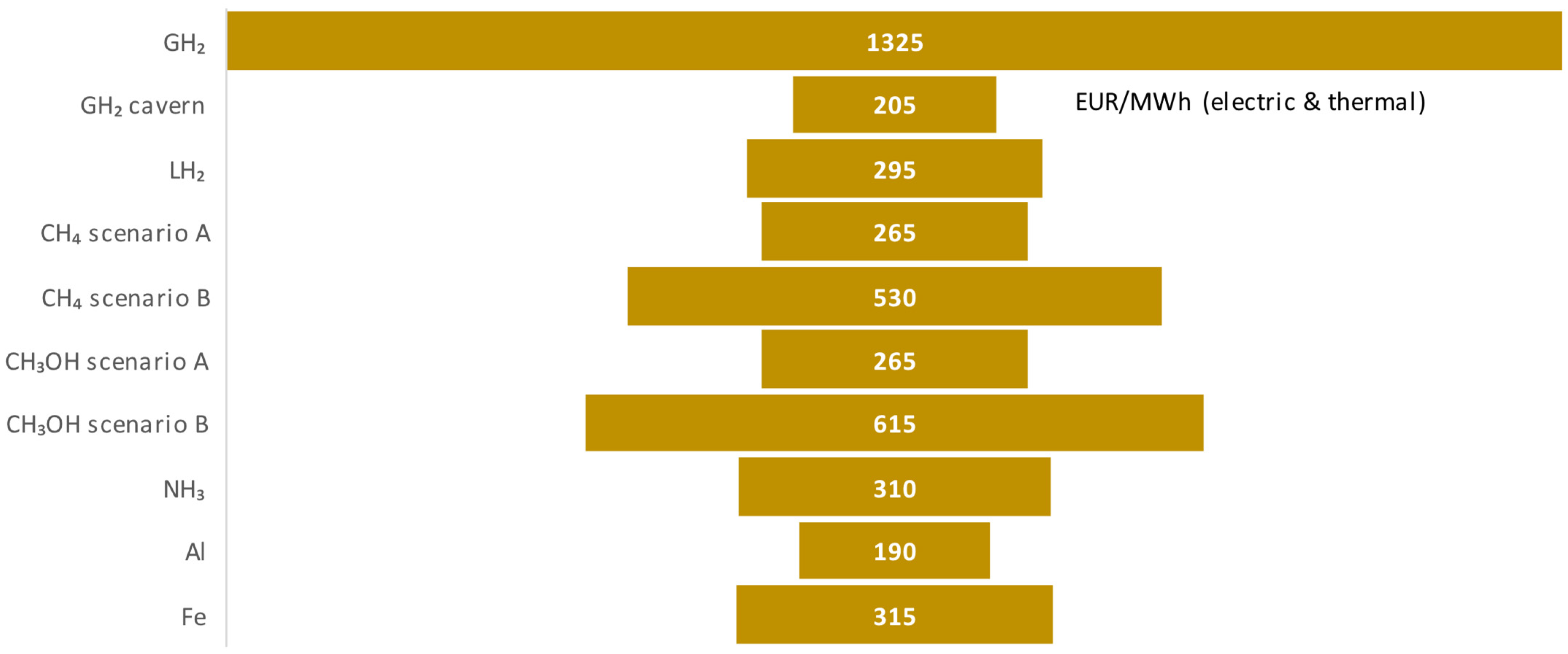
| LCOXS, EUR/MWh | 1.3k | 215 | 295 | 265 | 530 | 265 | 615 | 310 | 180 | 330 |
| Literature | [26,48,74,75,94,95,96] | [82,85,94] | [87,90] | |||||||
References
- Adl-Zarrabi, B.; Bauer, D.; Bokhoven, T.; Çetin, A.; Doetsch, C.; Hauer, A.; Ooka, R.; Rathgeber, C.; van Helden, W.; Wagener, P. Energy Storage IEA Technology Collaboration Programme: Annual Report; International Energy Agency: Paris, France, 2021. [Google Scholar]
- Sterner, M.; Stadler, I. Energiespeicher—Bedarf, Technologien, Integration; Springer: Berlin/Heidelberg, Germany, 2014; ISBN 978-3-642-37379-4. [Google Scholar]
- Cole, W.; Karmakar, A. Cost Projections for Utility-Scale Battery Storage: 2023 Update; National Renewable Energy Lab. (NREL): Golden, CO, USA, 2023. [Google Scholar]
- Brækken, A.; Sannan, S.; Jerca, I.O.; Bădulescu, L.A. Integrated Heating and Cooling System with Borehole Thermal Energy Storage for a Greenhouse in Romania. Therm. Sci. Eng. Prog. 2024, 55, 102910. [Google Scholar] [CrossRef]
- Koornneef, J.; Guglielmetti, L.; Hahn, F.; Egermann, P.; Vangkilde, T.; Aradottir, E.S.; Allaerts, K.; Viveiros, F.; Saaltink, M. Heatstore: High Temperature Underground Thermal Energy Storage. In Proceedings of the European Geothermal Congress 2019, The Hague, The Netherlands, 11–14 June 2019. [Google Scholar]
- SUSHEAT EU Project. Available online: https://susheat.eu/demo-sites/ (accessed on 28 February 2025).
- Wulf, C.; Zapp, P.; Schreiber, A. Review of Power-to-X Demonstration Projects in Europe. Front. Energy Res. 2020, 8, 191. [Google Scholar] [CrossRef]
- Large-Scale-Electricity-Storage. Available online: https://royalsociety.org/-/media/policy/projects/large-scale-electricity-storage/large-scale-electricity-storage-report.pdf (accessed on 25 February 2025).
- ECHEMI. Xylitol Price and Market Analysis. Available online: https://www.echemi.com/productsInformation/temppid160705012013-xylitol.html (accessed on 16 August 2022).
- Sorbitol Prices, News, Demand, Analysis & Forecast. Available online: https://www.imarcgroup.com/sorbitol-pricing-report (accessed on 25 February 2025).
- Sodium Hydroxide Price Index. Available online: https://businessanalytiq.com/procurementanalytics/index/sodium-hydroxide-price-index/ (accessed on 25 February 2025).
- Silica Gel China Price Index. Available online: https://businessanalytiq.com/procurementanalytics/index/silica-gel-china-price-index/ (accessed on 25 February 2025).
- Auswertung Des Kostenpotentials—Wasserstoffatlas. Available online: https://wasserstoffatlas.de/en/potential-costs/evaluation?pot=costs&techProduct=elGen&calcBasis=EnTec&techSource=EEMix&nuts=nuts3&empl=h2relevanz_industry (accessed on 28 February 2025).
- IRENA Innovation Outlook: Thermal Energy Storage; International Renewable Energy Agency: Masdar City, Abu Dhabi, 2020.
- Hailu, G. Seasonal Solar Thermal Energy Storage; IntechOpen: Rijeka, Croatia, 2018; ISBN 978-1-78985-418-3. [Google Scholar]
- Mangold, D.; Deschaintre, L. Seasonal Thermal Energy Storage: Report on State of the Art and Necessary Further R+D. IEA SHC Task 2015, 45, 1–48. [Google Scholar]
- Yang, T.; Liu, W.; Kramer, G.J.; Sun, Q. Seasonal Thermal Energy Storage: A Techno-Economic Literature Review. Renew. Sustain. Energy Rev. 2021, 139, 110732. [Google Scholar] [CrossRef]
- Christian, H.; Speicher, T. Bilfinger Vam Anlagentechnik Gmbh; Tagung “Thermische Speicher”: Wien, Austria, 2019. [Google Scholar]
- Dahash, A.; Ochs, F.; Janetti, M.B.; Streicher, W. Advances in Seasonal Thermal Energy Storage for Solar District Heating Applications: A Critical Review on Large-Scale Hot-Water Tank and Pit Thermal Energy Storage Systems. Appl. Energy 2019, 239, 296–315. [Google Scholar] [CrossRef]
- Kraemer, S. Long-Duration Thermal Energy Storage in Sand Begins NREL Demo. Available online: https://www.solarpaces.org/100-hour-thermal-energy-storage-in-sand-begins-nrel-demo/ (accessed on 25 October 2024).
- Kakoko, L.D.; Jande, Y.A.C.; Kivevele, T. Experimental Investigation of Soapstone and Granite Rocks as Energy-Storage Materials for Concentrated Solar Power Generation and Solar Drying Technology. ACS Omega 2023, 8, 18554–18565. [Google Scholar] [CrossRef] [PubMed]
- Gomna, A.; N’Tsoukpoe, K.E.; Le Pierrès, N.; Coulibaly, Y. Review of Vegetable Oils Behaviour at High Temperature for Solar Plants: Stability, Properties and Current Applications. Sol. Energy Mater. Sol. Cells 2019, 200, 109956. [Google Scholar] [CrossRef]
- Steinmann, W.-D. Thermal Energy Storage for Medium and High Temperatures: Concepts and Applications; Springer Fachmedien: Wiesbaden, Germany, 2022; ISBN 978-3-658-02003-3. [Google Scholar]
- Reuss, M.; Beck, M. Design of a Seasonal Thermal Energy Storage in the Ground. Sol. Energy 1997, 59, 247–257. [Google Scholar] [CrossRef]
- IEA ES Task 39—Large Thermal Energy Storages for Distric Heating. Available online: https://iea-es.org/annex-39/ (accessed on 25 March 2022).
- Bott, C.; Dressel, I.; Bayer, P. State-of-Technology Review of Water-Based Closed Seasonal Thermal Energy Storage Systems. Renew. Sustain. Energy Rev. 2019, 113, 109241. [Google Scholar] [CrossRef]
- BigStoreDH—Grosse Wärmespeicher Für Wärmenetze. Available online: https://www.ost.ch/de/forschung-und-dienstleistungen/technik/erneuerbare-energien-und-umwelttechnik/spf-institut-fuer-solartechnik/forschung/projekte/details/bigstoredh-grosse-waermespeicher-fuer-waermenetze-1194 (accessed on 6 November 2023).
- Mateusz, J. Techno-Economic Aspects of Seasonal Underground Storage of Solar Thermal Energy in Hard Crystalline Rocks. Doctoral Dissertation, Aalto University, Aalto, Finnland, 2019. [Google Scholar]
- Haller, M.; Ruesch, F. Fokusstudie Saisonale Wärmespeicher—Stand der Technik und Ausblick. Available online: https://speicher.aeesuisse.ch/wp-content/uploads/sites/15/2021/09/FESS_Fokusstudie_Saisonale_Waermespeicher.pdf (accessed on 21 November 2022).
- Fleuchaus, P.; Godschalk, B.; Stober, I.; Blum, P. Worldwide Application of Aquifer Thermal Energy Storage—A Review. Renew. Sustain. Energy Rev. 2018, 94, 861–876. [Google Scholar] [CrossRef]
- Geothermie Verband Schweiz Hochtemperaturspeicher Geospeicher Forsthaus in Bern. Available online: https://geothermie-schweiz.ch/wp_live/wp-content/uploads/2021/12/BE_Bern-Geospeicher_DE.pdf (accessed on 25 August 2022).
- Sanner, B.; Knoblich, K. Advantages and Problems of High Temperature Underground Thermal Energy Storage; Centred’Hydrogdologie, Universite’de Neuchlitel: Neuchâtel, Switzerland, 1999; p. 8. [Google Scholar]
- Fleuchaus, P.; Schüppler, S.; Bloemendal, M.; Guglielmetti, L.; Opel, O.; Blum, P. Risk Analysis of High-Temperature Aquifer Thermal Energy Storage (HT-ATES). Renew. Sustain. Energy Rev. 2020, 133, 110153. [Google Scholar] [CrossRef]
- Ueckert, M.; Baumann, T. Hydrochemical Aspects of High-Temperature Aquifer Storage in Carbonaceous Aquifers: Evaluation of a Field Study. Geotherm. Energy 2019, 7, 4. [Google Scholar] [CrossRef]
- Drijver, B.; van Aarssen, M.; de Zwart, B. High-Temperature Aquifer Thermal Energy Storage (HT-ATES)-sustainable and multi-usable: In Proceedings of the 12th International Conference on Energy Storage – Innostock, Lleida, Spain, 16 May 2012.
- Collignon, M.; Klemetsdal, Ø.S.; Møyner, O.; Alcanié, M.; Rinaldi, A.P.; Nilsen, H.; Lupi, M. Evaluating Thermal Losses and Storage Capacity in High-Temperature Aquifer Thermal Energy Storage (HT-ATES) Systems with Well Operating Limits: Insights from a Study-Case in the Greater Geneva Basin, Switzerland. Geothermics 2020, 85, 101773. [Google Scholar] [CrossRef]
- Vantaan Energia. The World’s Largest Cavern Thermal Energy Storage. Available online: https://www.vantaanenergia.fi/en/about-us/projects/varanto-the-cavern-thermal-energy-storage/ (accessed on 21 November 2022).
- Stadler, I.; Hauer, A. Thermische Energiespeicher. In Energiespeicher—Bedarf, Technologien, Integration; Sterner, M., Stadler, I., Eds.; Springer: Berlin/Heidelberg, Germany, 2017; pp. 579–618. ISBN 978-3-662-48893-5. [Google Scholar]
- Pagkalos, C.; Dogkas, G.; Koukou, M.K.; Konstantaras, J.; Lymperis, K.; Vrachopoulos, M.G. Evaluation of Water and Paraffin PCM as Storage Media for Use in Thermal Energy Storage Applications: A Numerical Approach. Int. J. Thermofluids 2020, 1–2, 100006. [Google Scholar] [CrossRef]
- Alferez Luna, M.P.; Neumann, H.; Gschwander, S. Stability Study of Erythritol as Phase Change Material for Medium Temperature Thermal Applications. Appl. Sci. 2021, 11, 5448. [Google Scholar] [CrossRef]
- Heat and Cold Storage with PCM; Springer Nature: Berlin/Heidelberg, Germany, 2008; ISBN 978-3-540-68556-2.
- Niknam, P.H.; Sciacovelli, A. Hybrid PCM-Steam Thermal Energy Storage for Industrial Processes—Link between Thermal Phenomena and Techno-Economic Performance through Dynamic Modelling. Appl. Energy 2023, 331, 120358. [Google Scholar] [CrossRef]
- Schreiber, H.; Lanzerath, F.; Reinert, C.; Grüntgens, C.; Bardow, A. Heat Lost or Stored: Experimental Analysis of Adsorption Thermal Energy Storage. Appl. Therm. Eng. 2016, 106, 981–991. [Google Scholar] [CrossRef]
- Hadorn, J.-C. Thermal Energy Storage for Solar and Low Energy Buildings; Servei de Publicacions Universidad Lleida: Lleida, Spain, 2005; 179p. [Google Scholar]
- Aydin, D.; Casey, S.P.; Riffat, S. The Latest Advancements on Thermochemical Heat Storage Systems. Renew. Sustain. Energy Rev. 2015, 41, 356–367. [Google Scholar] [CrossRef]
- Daguenet-Frick, X.; Gantenbein, P.; Müller, J.; Fumey, B.; Weber, R. Seasonal Thermochemical Energy Storage: Comparison of the Experimental Results with the Modelling of the Falling Film Tube Bundle Heat and Mass Exchanger Unit. Renew. Energy 2017, 110, 162–173. [Google Scholar] [CrossRef]
- Fumey, B.; Baldini, L. Static Temperature Guideline for Comparative Testing of Sorption Heat Storage Systems for Building Application. Energies 2021, 14, 3754. [Google Scholar] [CrossRef]
- Welch, A.J.; Digdaya, I.A.; Kent, R.; Ghougassian, P.; Atwater, H.A.; Xiang, C. Comparative Technoeconomic Analysis of Renewable Generation of Methane Using Sunlight, Water, and Carbon Dioxide. ACS Energy Lett. 2021, 6, 1540–1549. [Google Scholar] [CrossRef]
- Kylee, K.; Harris, K.; Grim, R.; Tao, L. A Comparative Techno-Economic Analysis of Renewable Methanol Synthesis Pathways from Biomass and CO2; Volume 11: Sustainable Energy Solutions for Changing the World: Part III; National Renewable Energy Lab. (NREL): Golden, CO, USA, 2021. [Google Scholar]
- The Royal Society. Ammonia: Zero-Carbon Fertiliser, Fuel and Energy Store; The Royal Society: London, UK, 2020; ISBN 978-1-78252-448-9. [Google Scholar]
- Andersson, J.; Grönkvist, S. Large-Scale Storage of Hydrogen. Int. J. Hydrogen Energy 2019, 44, 11901–11919. [Google Scholar] [CrossRef]
- Brinkman, L.; Bulfin, B.; Steinfeld, A. Thermochemical Hydrogen Storage via the Reversible Reduction and Oxidation of Metal Oxides. Energy Fuels 2021, 35, 18756–18767. [Google Scholar] [CrossRef]
- Dudita, M.; Farchado, M.; Englert, A.; Carbonell Sanchez, D.; Haller, M. Heat and Power Storage Using Aluminium for Low and Zero Energy Buildings. E3S Web Conf. 2019, 111, 04008. [Google Scholar] [CrossRef]
- Li, B.; Li, J.; Shao, H.; He, L. Mg-Based Hydrogen Absorbing Materials for Thermal Energy Storage—A Review. Appl. Sci. 2018, 8, 1375. [Google Scholar] [CrossRef]
- International Energy Agency. Global Hydrogen Review 2024; IEA: Paris, France, 2024; Available online: https://www.iea.org/reports/global-hydrogen-review-2024 (accessed on 2 December 2024).
- Okonkwo, E.C.; Al-Breiki, M.; Bicer, Y.; Al-Ansari, T. Sustainable Hydrogen Roadmap: A Holistic Review and Decision-Making Methodology for Production, Utilisation and Exportation Using Qatar as a Case Study. Int. J. Hydrogen Energy 2021, 46, 35525–35549. [Google Scholar] [CrossRef]
- Green Hydrogen Cost Reduction: Scaling Up Electrolysers to Meet the 1.5C Climate Goal. 2020. Available online: https://www.irena.org/-/media/Files/IRENA/Agency/Publication/2020/Dec/IRENA_Green_hydrogen_cost_2020.pdf (accessed on 25 October 2023).
- Ghaffari-Tabrizi, F.; Haemisch, J.; Lindner, D. Reducing Hydrogen Boil-Off Losses during Fuelling by Pre-Cooling Cryogenic Tank. Hydrogen 2022, 3, 255–269. [Google Scholar] [CrossRef]
- Kawasaki Completes Basic Design for World’s Largest Class (11,200-Cubic-Meter) Spherical Liquefied Hydrogen Storage Tank. Available online: https://global.kawasaki.com/en/corp/newsroom/news/detail/?f=20201224_8018 (accessed on 28 October 2022).
- Increase Hydrogen Supply Availability with Cavern Storage; Linde: Dublin, Ireland, 2022.
- Abdin, Z.; Tang, C.; Liu, Y.; Catchpole, K. Large-Scale Stationary Hydrogen Storage via Liquid Organic Hydrogen Carriers. iScience 2021, 24, 102966. [Google Scholar] [CrossRef]
- Underground Hydrogen Storage; Gaffney Cline: Alton, UK, 2022.
- Muhammed, N.S.; Haq, B.; Al Shehri, D.; Al-Ahmed, A.; Rahman, M.M.; Zaman, E. A Review on Underground Hydrogen Storage: Insight into Geological Sites, Influencing Factors and Future Outlook. Energy Rep. 2022, 8, 461–499. [Google Scholar] [CrossRef]
- Böhm, H.; Lehner, M.; Kienberger, T. Techno-Economic Assessment of Thermally Integrated Co-Electrolysis and Methanation for Industrial Closed Carbon Cycles. Front. Sustain. 2021, 2, 726332. [Google Scholar] [CrossRef]
- House, K.Z.; Baclig, A.C.; Ranjan, M.; van Nierop, E.A.; Wilcox, J.; Herzog, H.J. Economic and Energetic Analysis of Capturing CO2 from Ambient Air. Proc. Natl. Acad. Sci. USA 2011, 108, 20428–20433. [Google Scholar] [CrossRef] [PubMed]
- Tichler, R.; Bauer, S. Power-to-Gas. In Storing Energy; Letcher, T.M., Ed.; Elsevier: Oxford, UK, 2016; pp. 373–389. ISBN 978-0-12-803440-8. [Google Scholar]
- Gorre, J.; Ortloff, F.; van Leeuwen, C. Production Costs for Synthetic Methane in 2030 and 2050 of an Optimized Power-to-Gas Plant with Intermediate Hydrogen Storage. Appl. Energy 2019, 253, 113594. [Google Scholar] [CrossRef]
- Dias, V.; Pochet, M.; Contino, F.; Jeanmart, H. Energy and Economic Costs of Chemical Storage. Front. Mech. Eng. 2020, 6, 21. [Google Scholar] [CrossRef]
- CRI’s Largest CO2-to-Methanol Reactor Installed in Anyang. Available online: https://www.carbonrecycling.com/about/news/cris-largest-co2-to-methanol-reactor-installed-in-anyang (accessed on 17 June 2022).
- Methanol Institute. Atmospheric Above Ground Tank Storage of Methanol. Available online: https://www.methanol.org/wp-content/uploads/2016/06/AtmosphericAboveGroundTankStorageMethanol-1.pdf (accessed on 17 June 2022).
- Cox, A.W.; Lees, F.P.; Ang, M.L. (Eds.) Classification of Hazardous Locations: A Report of the Inter-Institutional Group on the Classification of Hazardous Locations (IIGCHL); Institution of Chemical Engineers: Rugby, UK, 1991; ISBN 978-0-85295-258-0. [Google Scholar]
- Ott, J.; Gronemann, V.; Pontzen, F.; Fiedler, E.; Grossmann, G.; Kersebohm, D.B.; Weiss, G.; Witte, C. Methanol. In Ullmann’s Encyclopedia of Industrial Chemistry; Wiley-VCH Verlag GmbH & Co. KGaA: Weinheim, Germany, 2012; ISBN 978-3-527-30673-2. [Google Scholar] [CrossRef]
- Simon Araya, S.; Liso, V.; Cui, X.; Li, N.; Zhu, J.; Sahlin, S.L.; Jensen, S.H.; Nielsen, M.P.; Kær, S.K. A Review of The Methanol Economy: The Fuel Cell Route. Energies 2020, 13, 596. [Google Scholar] [CrossRef]
- Patonia, A.; Poudineh, R. Ammonia as a Storage Solution for Future Decarbonized Systems; The Oxford Institute for Energy Studies: Oxford, UK, 2020; ISBN 978-1-78467-167-9. [Google Scholar]
- Guidance for Inspection of Atmospheric Refrigerated Ammonia Storage Tanks; Fertilizers Europe: Brussels, Belgium, 2014.
- Siddiqui, O.; Dincer, I. Development of a New Ammonia-Based Energy Storage Option for Grid Balancing. Energy Storage 2020, 2, e145. [Google Scholar] [CrossRef]
- Steinfeld, A. Solar Thermochemical Production of Hydrogen––A Review. Sol. Energy 2005, 78, 603–615. [Google Scholar] [CrossRef]
- Agrafiotis, C.; Roeb, M.; Sattler, C. A Review on Solar Thermal Syngas Production via Redox Pair-Based Water/Carbon Dioxide Splitting Thermochemical Cycles. Renew. Sustain. Energy Rev. 2015, 42, 254–285. [Google Scholar] [CrossRef]
- Bergthorson, J.M.; Goroshin, S.; Soo, M.J.; Julien, P.; Palecka, J.; Frost, D.L.; Jarvis, D.J. Direct Combustion of Recyclable Metal Fuels for Zero-Carbon Heat and Power. Appl. Energy 2015, 160, 368–382. [Google Scholar] [CrossRef]
- Trowell, K.A.; Goroshin, S.; Frost, D.L.; Bergthorson, J.M. Aluminum and Its Role as a Recyclable, Sustainable Carrier of Renewable Energy. Appl. Energy 2020, 275, 115112. [Google Scholar] [CrossRef]
- Haller, M.Y.; Carbonell, D.; Dudita, M.; Zenhäusern, D.; Häberle, A. Seasonal Energy Storage in Aluminium for 100 Percent Solar Heat and Electricity Supply. Energy Convers. Manag. X 2020, 5, 100017. [Google Scholar] [CrossRef]
- Carbon Free Aluminium Production. Available online: https://www.elysis.com/en/what-is-elysis (accessed on 25 August 2022).
- Production of Inert Metallic Anodes. Available online: https://www.trimet.eu/en/trimet/sustainability/environmental-and-climate-protection/production-of-inert-metallic-anodes (accessed on 28 February 2025).
- Ersoy, H.; Baumann, M.; Barelli, L.; Ottaviano, A.; Trombetti, L.; Weil, M.; Passerini, S. Hybrid Energy Storage and Hydrogen Supply Based on Aluminum—A Multiservice Case for Electric Mobility and Energy Storage Services. Adv. Mater. Technol. 2022, 7, 2101400. [Google Scholar] [CrossRef]
- Haller, M.; Dudita, M.; Baeuerle, Y. Aluminium-Redox-Cycles for the Production of Heat and Electricity for Buildings Based on Renewable Energies; Institut for Solar Technology: Selangor, Malaysia, 2022; p. 53. [Google Scholar]
- Pei, M.; Petäjäniemi, M.; Regnell, A.; Wijk, O. Toward a Fossil Free Future with HYBRIT: Development of Iron and Steelmaking Technology in Sweden and Finland. Metals 2020, 10, 972. [Google Scholar] [CrossRef]
- Vogl, V.; Åhman, M.; Nilsson, L.J. Assessment of Hydrogen Direct Reduction for Fossil-Free Steelmaking. J. Clean. Prod. 2018, 203, 736–745. [Google Scholar] [CrossRef]
- Cavaliere, P. Hydrogen Assisted Direct Reduction of Iron Oxides; Springer International Publishing: Cham, Switzerland, 2022; ISBN 978-3-030-98055-9. [Google Scholar]
- Allanore, A. Features and Challenges of Molten Oxide Electrolytes for Metal Extraction. J. Electrochem. Soc. 2015, 162, E13–E22. [Google Scholar] [CrossRef]
- Green Steel Solution. Available online: https://www.bostonmetal.com/green-steel-solution/ (accessed on 30 May 2023).
- International Energy Agency DHC. Pit Thermal Energy Storage for Smart District Heating and Cooling; IEA DHC Annex XII; IEA DHC: Stuttgart, Germany, 2020; Available online: https://www.iea-dhc.org/index.php?id=528 (accessed on 10 October 2022).
- Schmidt, T.; Baeuerle, Y.; Haller, M.; Ruesch, F. Kosten und Wirtschaftlichkeit. Available online: https://www.ost.ch/fileadmin/dateiliste/3_forschung_dienstleistung/institute/spf/forschung/projekte/bigstoredh-factsheet-kosten-wirtschaftlichkeit.pdf (accessed on 9 February 2024).
- Solites - Das Wissensportal für die saisonale Wärmespeicherung. Available online: https://www.saisonalspeicher.de/home/speichertypen/erdsonden/groesse/ (accessed on 9 February 2024).
- U.S. Department of Energy. Comparison of Fuel Cell Technologies; Fuel Cell Technologies Office: Washingthon, DC, USA, 2016. Available online: https://www.energy.gov/sites/default/files/2016/06/f32/fcto_fuel_cells_comparison_chart_apr2016.pdf (accessed on 28 October 2022).
- Jeerh, G.; Zhang, M.; Tao, S. Recent Progress in Ammonia Fuel Cells and Their Potential Applications. J. Mater. Chem. A 2021, 9, 727–752. [Google Scholar] [CrossRef]
- Leighty, W.C.; Holbrook, J.H. Alternatives to Electricity for Transmission, Firming Storage, and Supply Integration for Diverse, Stranded, Renewable Energy Resources: Gaseous Hydrogen and Anhydrous Ammonia Fuels via Underground Pipelines. Energy Procedia 2012, 29, 332–346. [Google Scholar] [CrossRef]
- De la Fuente, D.; Otero-Huerta, E.; Morcillo, M. Studies of Long-Term Weathering of Aluminium in the Atmosphere. Corros. Sci. 2007, 49, 3134–3148. [Google Scholar] [CrossRef]
- Dubey, P. Efficient Pit Project: Together with Its Partners, Solmax Is Developing the next Generation of Pit Thermal Energy Storage. Available online: https://informedinfrastructure.com/67506/efficient-pit-project-together-with-its-partners-solmax-is-developing-the-next-generation-of-pit-thermal-energy-storage/ (accessed on 28 October 2022).


| TES | P2X | |
|---|---|---|
| Application | TES and P2X serve distinct purposes, making direct comparisons challenging. | |
| Energy requirements | Systems typically use waste heat (a lower-quality energy source) for charging. This waste heat generally incurs no additional OPEXcharging. OPEX for components like heat exchangers is minimal in most cases (except for borehole thermal energy storage, thermochemical storage and phase change materials). | Processes require electricity (the highest quality of energy) for chemical conversion. This incurs higher OPEXcharging. |
| Energy recovery | Heat only. | Heat and electricity, with electricity being of higher economic value. |
| Cost drivers | The primary cost driver for TES systems is CAPEXstorage. | The main cost driver is OPEXP2X for charging the storage, not CAPEXstorage, except for pressurized hydrogen storage tanks. |
| Storage efficiency | High storage efficiency (minimal losses), which is dependent on the temperature difference between the storage system and its surroundings. | Storage efficiency depends on fuel type and conversion process (e.g., electrolysis). |
| Storage material/medium | Typically non-toxic, non-flammable materials like water or molten salts. | This requires compatibility with chemical fuels like hydrogen or methane. |
| Water | Sandstone | |
|---|---|---|
| Storage capacity | Higher (up to 6 GWh) | Lower (up to 1 GWh) |
| Temperature range, °C | 20 to 95/130/160 | 60 to 400 |
| Temperature swing considered | 50 | |
| Volumetric heat capacity, MJ/(m3·K) | 4.13 | 2.8 |
| Storage material cost, EUR/kWh (thermal) | 0.09 | 0.88 |
| PTES | BTES | ATES | |
|---|---|---|---|
| Storage capacity, GWh | Up to 60 | Up to 6 | 0.6 to 40 |
| Temperature range, °C | 10 to 95 | 10 to 80 | Up to 95 |
| Storage density, kWh/m3 | 40 to 80 | 25 to 40 | 20 to 40 |
| Recovery efficiency, % | 90 to 95 | 70 to 80 | 40 to 80 |
| Erythritol | Xylitol | Sorbitol/Glucol | |
|---|---|---|---|
| Phase change temperature, °C | 117/121 | 94/92.7 | 55/110; 93.5/94.5 |
| Temperature swing considered | 10 | ||
| Latent heat of fusion, kJ/kg | 340/344 | 246/260 | 166/173 |
| Storage material cost, EUR/kWh (thermal) | 8.3 | 13.8 | 29 |
| Sodium Hydroxide | Silica Gel | |
|---|---|---|
| Temperature range, °C | 40 to 150 | 130 to 150 |
| Enthalpy of adsorption, kJ/kg | 540 | 1000 |
| Storage material cost, EUR/kWh (thermal) | 0.5 to 0.8 | 0.8 to 1.3 |
Disclaimer/Publisher’s Note: The statements, opinions and data contained in all publications are solely those of the individual author(s) and contributor(s) and not of MDPI and/or the editor(s). MDPI and/or the editor(s) disclaim responsibility for any injury to people or property resulting from any ideas, methods, instructions or products referred to in the content. |
© 2025 by the authors. Licensee MDPI, Basel, Switzerland. This article is an open access article distributed under the terms and conditions of the Creative Commons Attribution (CC BY) license (https://creativecommons.org/licenses/by/4.0/).
Share and Cite
Baeuerle, Y.I.; Arpagaus, C.; Haller, M.Y. A Review of Seasonal Energy Storage for Net-Zero Industrial Heat: Thermal and Power-to-X Storage Including the Novel Concept of Renewable Metal Energy Carriers. Energies 2025, 18, 2204. https://doi.org/10.3390/en18092204
Baeuerle YI, Arpagaus C, Haller MY. A Review of Seasonal Energy Storage for Net-Zero Industrial Heat: Thermal and Power-to-X Storage Including the Novel Concept of Renewable Metal Energy Carriers. Energies. 2025; 18(9):2204. https://doi.org/10.3390/en18092204
Chicago/Turabian StyleBaeuerle, Yvonne I., Cordin Arpagaus, and Michel Y. Haller. 2025. "A Review of Seasonal Energy Storage for Net-Zero Industrial Heat: Thermal and Power-to-X Storage Including the Novel Concept of Renewable Metal Energy Carriers" Energies 18, no. 9: 2204. https://doi.org/10.3390/en18092204
APA StyleBaeuerle, Y. I., Arpagaus, C., & Haller, M. Y. (2025). A Review of Seasonal Energy Storage for Net-Zero Industrial Heat: Thermal and Power-to-X Storage Including the Novel Concept of Renewable Metal Energy Carriers. Energies, 18(9), 2204. https://doi.org/10.3390/en18092204