Article

Thermal Performance of Deep Borehole Heat Exchangers (DBHEs) Installed in a Groundwater-Filled Hot Dry Rock (HDR) Well in Qinghai, China

by
Qixing Zhang
1,2,3,
Feiyang Lu
3,
Yong Huang
1,2,
Liwei Tan
1,2,
Jin Luo
3 and
Longcheng Duan
3,*
1
Hydro Geology and Engineering Geology and Environmental Geology Survey Institute of Qinghai Province, Xining 810008, China
2
Hydrogeological and Geothermal Geological Key Laboratory of Qinghai Province, Xining 810008, China
3
Faculty of Engineering, China University of Geosciences (Wuhan), Wuhan 430074, China
*
Author to whom correspondence should be addressed.
Energies 2025, 18(9), 2229; https://doi.org/10.3390/en18092229
Submission received: 6 March 2025 / Revised: 4 April 2025 / Accepted: 21 April 2025 / Published: 27 April 2025
(This article belongs to the Section J1: Heat and Mass Transfer)

Abstract

:
Deep borehole heat exchangers (DBHEs) have been widely used for extracting geothermal energy in China. However, the application of this technology in an open well with high temperature remains unknown. In this paper, the thermal performance of a DBHE installed in a groundwater-filled hot dry rock (HDR) well in the Gonghe Basin of Qinghai Province in China was investigated. A U-shaped pipe subjected to a hydraulic pressure of 30 MPa and a temperature of 180 °C was tested successfully. Severe heat loss was detected during the test, which might have been due to the pipe not being well-insulated. To better understand the performance of DBHEs, a numerical model was developed. The results indicate that the pipe’s thermal performance increased by 247% using insulation with a 15 mm layer thickness and a thermal conductivity of 0.042 W/m·K. Thermal performance was significantly improved by increasing the fluid flow rate and pipe diameter. Among the different pipe configurations, double U-shaped buried pipes can achieve the highest performance. The heat-specific rate can reach up to 341.33 W/m with a double U-shaped pipe with a diameter of 63 mm. The second highest rate can be achieved with a coaxial pipe, while single U-shaped pipes have the lowest one.

1. Introduction

Nowadays, the significance of renewable energy resources in industrial production and daily life is becoming more and more important. Hot dry rock (HDR) resources constitute a pivotal energy source, residing within deep, high-temperature rock formations without the presence of fluids. These resources can be effectively harnessed using current technological advancements [1]. HDR is characterized by its abundant availability, minimal environmental footprint, and clean and non-polluting nature, rendering it an ideal, accessible, and sustainable green energy source in the future [2]. Compared with wind and solar power, HDR-based power generation boasts a notably higher capacity factor, ranging from 70% to 80%, as opposed to 16% and 30% for wind and solar power, respectively. Furthermore, the carbon emission intensity of HDR is substantially lower than that of coal-fired thermal power [3]. Consequently, the utilization of HDR geothermal resources has emerged as a strategic focus for energy policies worldwide, particularly in developed nations.
HDR geothermal resources are typically defined as high-temperature rock bodies exceeding 150 °C, situated within the Earth’s crust at depths ranging from 3 to 10 km [4]. The thermal energy of HDR is predominantly stored in hard rock formations, such as dense metamorphic or crystalline rocks. The high temperatures and unique physical characteristics of these formations pose significant challenges for drilling wells and reservoir construction. Additionally, the complex geological conditions in the deep parts of the Earth’s crust further complicate the process. Consequently, HDR currently represents the least exploited geothermal resource. It has been reported that the exploitable HDR reserves in the crust amount to approximately 1.3 × 1027 J, which could be utilized globally for approximately 217 million years [5,6]. Therefore, HDR may occupy an irreplaceable position in future energy structures.
The major approach for exploiting HDR resources worldwide is an enhanced geothermal system (EGS). This approach involves artificially constructing thermal reservoirs in low-permeability HDR formations. Heat energy is extracted by injecting cold water into the HDR reservoir, which is subsequently heated and pumped back to the surface. The extracted hot water is then utilized for thermoelectric exchange [7]. Reservoir construction is the cornerstone of EGS and involves various techniques, including hydraulic fracturing, explosive methods, thermal stress, and chemical stimulation [8]. Among these, hydraulic fracturing is the most widely utilized technology for creating artificial thermal reservoirs. However, its application is often constrained by stress, and deep rock structures at actual development sites are typically complex. Consequently, hydraulic fracturing can alter the stress state of the shallow crust, potentially leading to large-scale seismic events and associated hazards, raising significant public safety concerns.
Alternatively, a closed system was developed in which cold water is injected into the outer pipe, where it absorbs heat from the surrounding rock or soil as it descends [9]. Once the water reaches the bottom of the buried pipe, it is transported upward through the inner pipe as heated water. Upon returning to the surface, the heat pump extracts the heat for building heating, and the cooled circulating water re-enters the underground heat exchange system. This cycle continuously transfers heat from the surrounding rock or soil to the surface. Many studies have been carried out to investigate thermal performance of such deep borehole heat exchangers (DBHEs) [10]. Niu et al. investigated heat performance of a coaxial heat exchanger in HDR in Tangshan, China. Their study indicated that heat extraction power was influenced by operating conditions, material properties, and geological conditions [11]. Wang et al. found that the heat capacity of the fluid has a great impact on the heat performance of a DBHE [12]. In addition, ground temperature recovery was found to be very important to the long-term performance of a DBHE [13].
However, DBHEs installed in an open HDR-based geothermal well, which is expected to have high thermal performance, are rarely explored. This study presents an experiment and a numerical simulation of a fluid injection system in a 3102-m-deep HDR well. The primary objective of this paper was to identify the limitations of the existing experimental approaches and propose an enhanced heat exchange scheme associated with optimized heat extraction strategies. The remainder of the paper is structured as follows. Section 2 provides an overview of the study area and single-hole heat transfer experiments [14]. It also introduces a numerical model to evaluate the effects of pipeline thermal insulation on heat transfer efficiency, the influence of pipe diameter and flow rate, and the development of a numerical platform for analyzing various heat transfer scenarios. Section 3 outlines the research methodology and presents the key findings, while Section 4 summarizes the conclusions.

2. Geological Setting and Study Methodology

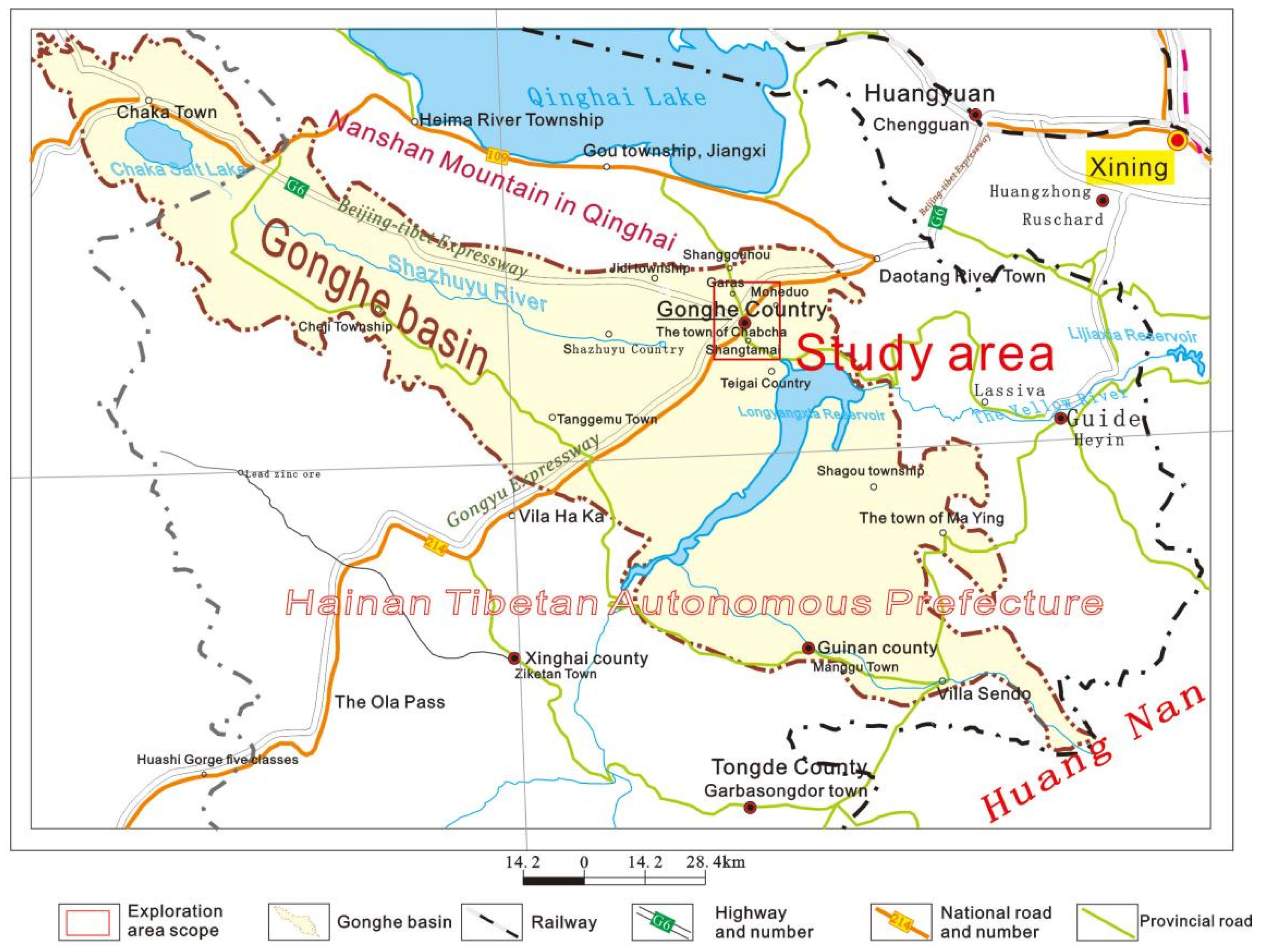
2.1. Geological Setting

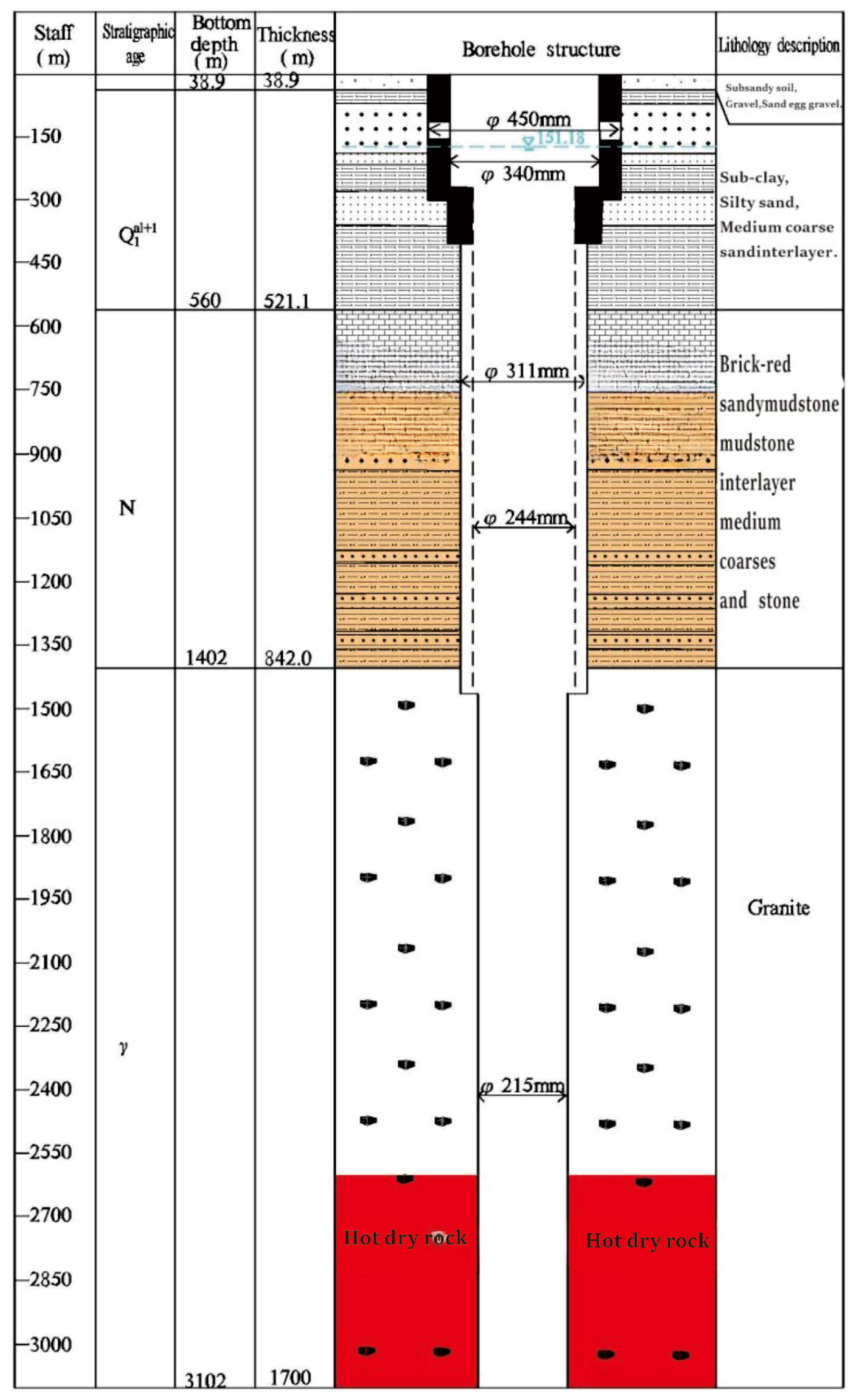
2.1.1. Stratigraphic Lithology

The study area is situated at the town of Chabcha, within the Republican County, part of the Hainan Tibetan Autonomous Prefecture in Qinghai Province, China. The region is characterized by faults that extend from the crust into the mantle’s soft layer, allowing heat to flow into the shallow crust, as illustrated in Figure 1. This geological setting creates favorable conditions for HDR formation in the Chabcha region. As shown in Figure 2, the sedimentary strata exposed by drilling in the study area, from the lowest to the highest layers, include the Paleo–Neoproterozoic Formation (EN1x), the Middle Neoproterozoic Formation (N1x), the Late Neoproterozoic Formation (N2l), and the Republican Formation of the Quaternary System [15,16]. Additionally, the Middle to Late Pleistocene (Q3–4) strata are present. These sedimentary layers, predominantly composed of mudstone and sandstone, have a thickness ranging from 900 to 1440 m, providing effective insulation as a geothermal cap in the Gonghe area. The presence of substantial granite intrusions further enhances the region’s geothermal potential by acting as efficient conduits for heat flow, thereby facilitating the formation and accumulation of geothermal resources within the Republican region.

2.1.2. Geothermal Conditions

The geothermal resources present in the Gonghe Basin of Qinghai Province are distributed in a relatively uniform manner, with the majority of geothermal reservoirs situated within the Indo–Chinese granite stratum at depths below 2100 m. In the Chabcha region, the temperature gradient observed in the basal granite section ranges from 39 °C to 45.2 °C/km, with an average geothermal gradient of 41 °C/km. The temperature gradient of the basal granite section in the Chabcha area of the Republican Basin is approximately 39.0–45.2 °C/km, with an average value of 41.3 °C/km. The thermal conductivity ranges from 2.07 to 2.31 W/(m·K), with an average value of 2.51 W/(m·K). The majority of the data (81%) is concentrated within the range of 2.3–2.9 W/(m·K). Evidence of geothermal anomalies is discernible in the Chabcha region.
The petrographic and mineralogical identification indicates that the HDR body in the Chabcha area is primarily composed of black mica granite diorite, porphyritic diorite, and granite, constituting a complex rock body. In previous studies conducted in this area, samples from boreholes were analyzed for their density, specific heat, and thermal conductivity [17]. The specific heat ranged from 0.896 to 1.715 kJ/(kg·K), while the thermal conductivity ranged from 0.328 to 1.825 W/(m·K).

2.2. Study Methodology

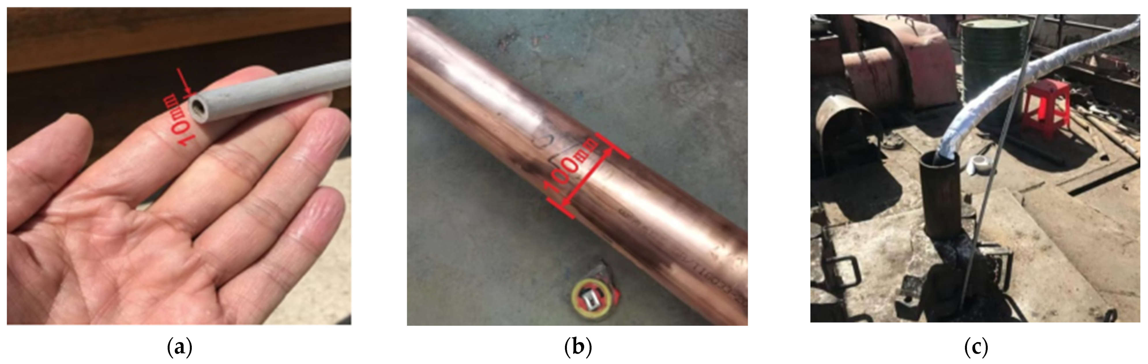
2.2.1. In Situ Test Setup

Based on the test drilling logs, well temperature, and diameter structure, combined with the gravity and mechanical performance requirements of the diversion device, the heat diversion injection system was designed for a depth of 3102 m. The main components include a heat extractor, a copper scattering tee, an outlet pipe, a water injection pipe, a centralizer, and a guide [18,19]. The fluid inlet pipe transports the water medium to the bottom of the drilling hole. Meanwhile, the outlet pipe is responsible for carrying high-temperature water to the surface. The pipes have an outer diameter of 10 mm and an inner diameter of 6 mm. The system’s suspended weight is supported by the drill pipe. It operates as a closed system with no leakage in the well [20]. Thermal fluid circulates within the system at a depth of 3102 m, enabling stable heat flow extraction. The system is designed to withstand high pressure, high temperature, and high humidity, meeting the requirements of a 300 mm bore diameter. The well’s outer and inner sections work together to form a circulation loop. A heat exchanger is employed to transfer the extracted heat, facilitating the recycling of thermal fluid. Figure 3 depicts the overall schematic diagram of the heat exchange device along with the on-site installation and operation effectiveness diagrams.
The ground heat exchanger is composed of an injection pipe with a 10 mm diameter and an insulated upflow pipe with a 10 mm diameter as well. Both pipes are connected at the top, which acts as a U-shaped heat exchanger. The pipe used in the experiment is made of a copper–nickel alloy with a density of 8.86–8.9 g/cm3. The highest yield strength is around 130 MPa, and the highest temperature resistance is 400 °C. The pipe is insulated above the ground surface to avoid the influence of cold ambient air. The system is driven by a water-circulating pump to form fluid circulation through the pipe, as shown in Figure 4. Heat is extracted by conduction due to the temperature difference between the fluid and the geothermal reservoir.

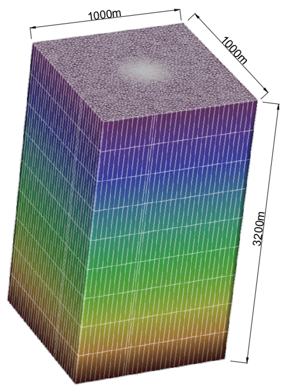
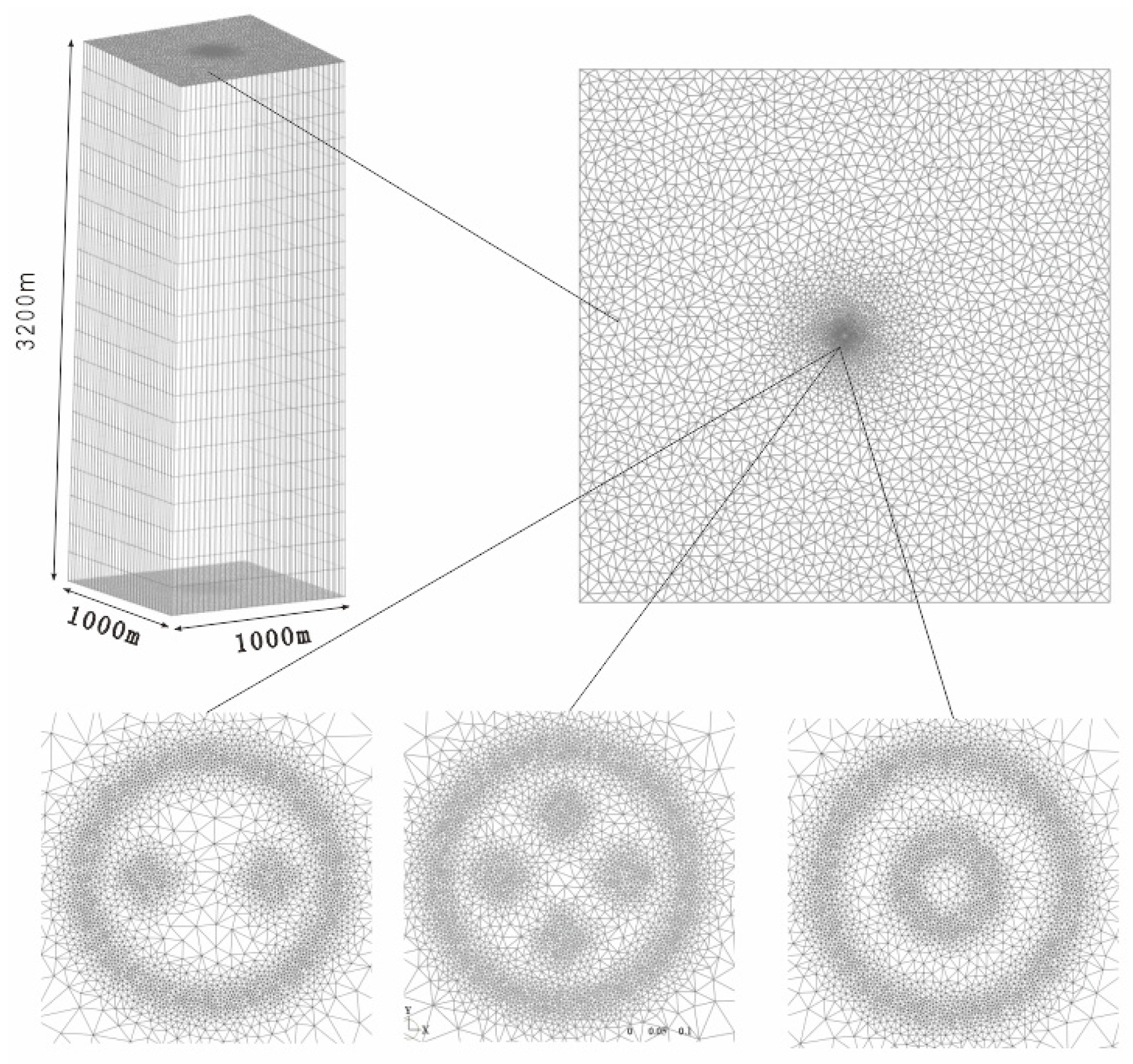
2.2.2. Development of a Numerical Model

A numerical model was built in FEFLOW 6.0 (Finite Element subsurface FLOW system) software [21]. The buried tube’s heat transfer process studied in this paper involves a three-dimensional heat transfer along the horizontal and vertical directions, with full consideration given to the heat transfer process between the wall of the buried pipe’s heat exchanger and the soil. Heat transfer in porous media encompasses heat conduction and heat convection, where the heat convection process satisfies Darcy’s law, and the heat conduction control equation is derived reasonably.
The hydrogeological parameters, hydrogeological initial conditions, and geothermal initial conditions were set up in the underground heat transfer model according to the logged borehole information. As shown in Figure 5, the initial conditions of the ground temperature were assigned to the model. According to the field measurements, the buried pipe’s configuration parameters assigned to the model are shown in Table 1.
By comparing the temperature difference between the observed data and the simulated results, the root mean square error (RMSE) was 0.165 °C, indicating that the model’s accuracy was within the range of the on-site measurement accuracy. This means the model has sufficiently high accuracy to predict the heat transfer performance of a GHE in this specific well [22].

2.2.3. Effects of Pipe Configuration and Low Rate on Heat Transfer Performance

This study simulates the heat exchange process of the vertical heat exchanger in the test and addresses thermal insulation measures for the outlet of the downhole pipe (see Table 2 in the model’s setup). The thermal conductivity of the insulation material used in the simulation is 0.042 W/(m·K). According to the thermal insulation measures applied to the buried pipe, the outlet temperature changes in response to the effect of the pipe insulation on the heat transfer efficiency of the buried pipe. Moreover, due to a small pipe being used as a heat exchanger in the experiment, the numerical study extended the pipe diameter associated with varying fluid flow rates to examine the heat transfer performance of the pipes [23].

2.2.4. Thermal Performance with Three Pipe Configurations

The heat transfer performance of GHEs with various configurations was specifically designed for HDR resource development. This numerical platform allows for adjustments to pipe diameters and wall thicknesses of different buried pipe types to simulate their heat transfer process. It provides a comprehensive numerical solution for comparing different operating conditions of GHEs in HDR thermal energy utilization. This study focused on three types of buried pipes: single U-shaped, double U-shaped, and coaxial, as shown in Figure 6.
As shown in the Table 3, the model’s domain was set to 1000 m × 1000 m × 3200 m, with a borehole diameter of 215 mm. Simulations were conducted to analyze the heat transfer performance under various configurations by adjusting pipe types, diameters, wall thicknesses, and insulation coefficients. These simulations enabled the development of discrete heat transfer models for each pipe type, with schematic diagrams presented in Figure 7. In the models for the three pipe types, the key parameters included a fluid flow rate of 30 m3/d, a center-to-center distance of 80 mm between the inlet and the outlet for single and double U-shaped pipes, and thermal conductivity values of 0.042 W/(m·K) for insulated pipes. By simulating different pipe diameters and matching wall thicknesses, the platform aims to investigate the optimal heat transfer efficiency for single U-shaped, double U-shaped, and coaxial buried pipes, providing valuable insights into their performance and design optimization.

3. Results and Discussion

3.1. Experimental Results

In this study, we successfully installed and operated a heat transfer fluid injection system for single-hole heat extraction in a 3102-m-deep HDR well. The system achieved over 24 h of safe and stable operation under extreme conditions of 30 MPa hydraulic pressure and temperatures exceeding 180 °C. During the experiment, the maximum fluid injection pressure reached 3.9 MPa, indicating that the experimental apparatus operated safely under such harsh conditions. However, significant heat loss was detected due to inadequate insulation of the test pipeline.
The system extracted thermal energy from deep underground and successfully achieved heat exchange, meeting the target parameters for the heat transfer fluid, under natural flow conditions with a height difference of 3 m and injection pressures ranging from 1.0 to 3.9 MPa. During testing, the maximum water discharge temperature reached 26.7 °C, with an average inflow rate of 120 L/h and an average discharge rate of 61.45 L/h. After resealing, the maximum temperature difference between the discharge and the inflow water was 12 °C, with an average temperature difference of 9.14 °C. These results indicate that at the same well depth, both water output and temperature increased with rising injection pressure. Specifically, for every 1.0 MPa increase in pressure, the water output increased by 10.23 L/h, and the water temperature rose by 2.3 °C. Moreover, the fluid pressure increase led to the increase in flow rate, and this resulted in the increase in heat transfer efficiency. Similar findings were reported by Manzoor and Saghir [24].
Through the operational tests, this study successfully developed a heat transfer fluid injection technology and device system for heat extraction in single-hole HDR wells. The system resists the challenges of high temperature, high pressure, and high humidity, demonstrating stable operation under conditions of 30 MPa pressure, temperatures exceeding 180 °C, and high humidity within the well. The trial operation validated the feasibility of the system for extracting HDR geothermal energy. Furthermore, the system cycle operated stably and reliably, offering relatively low costs and high cost-effectiveness. No significant crystalline sludge was observed, and the pressure and heat exchanger components showed no signs of electrochemical corrosion or leakage, ensuring good durability. By improving mass flow rates and optimizing thermal insulation measures, this technology holds great potential for application in the clean energy industry.

3.2. Effects of Pipe Insulation on Thermal Performance

Through simulation analysis, the temperature distribution curves of a single U-shaped buried pipe with a diameter of 50 mm in the vertical direction after 48 h of heat exchange at a flow rate of 20 m3/d, 30 m3/d, 60 m3/d, and 90 m3/d were obtained (as shown in Figure 8).
Figure 8 displays the fluid temperature change variation along the flow path with different fluid flow rates. The black boxes shown in the figure represent the points where the fluidd temperature turns decreasing, meaning the drastic heat loss. It shows temperature increases with increasing depth in the downward flow. However, the fluid temperature dropped in the upward flow, as shown in the black dots in all the sub figures. This means there was heat loss in the pipe instead of heat extraction in the well. It is observed that this peak point shifted higher and the fluid outlet temperature became higher as well when the fluid flow rates increased, implying that the higher the flow rate, the greater the thermal performance. When the flow rate was 20 m3/d, the final distance was 2800–3000 m; when the flow rate increased to 90 m3/d, the final displacement reduced to 2200–2400 m.
This study also simulated the impact of different insulation layer thicknesses on the fluid outlet temperature and heat exchange efficiency of the pipe in the experiments. The simulation results indicate that after 48 h of continuous operation, the outlet temperatures of the heat exchanger pipe with insulation layer thicknesses of 0 mm, 5 mm, 10 mm, and 15 mm were 43.15 °C, 62.34 °C, 76.71 °C, and 91.26 °C. The corresponding heat transfer rates per unit length were 3.3 W/m, 6.41 W/m, 8.85 W/m, and 11.45 W/m, as shown in Figure 9 respectively. These results demonstrate that the insulation layer has a significant impact on the heat transfer system, with thicker insulation layers leading to a higher heat transfer efficiency. In practical engineering applications, a combination of various materials can be employed to enhance the insulation effect of extraction wells.

3.3. The Influence of Pipe Diameter and Fluid Flow Rate on Heat Performance

To investigate the extension of the tested heat exchanger, four different pipe diameters of 40 mm, 50 mm, 63 mm, and 75 mm, each with five fluid flow rates of 20 m3/d, 30 m3/d, 40 m3/d, 50 m3/d, and 60 m3/d, were simulated. The results show that the heat extraction performance was enhanced by increasing the fluid flow rates for all the pipe diameters. The simulated fluid outlet temperature increased from 49.69 °C to 78.04 °C when the fluid flow rate increased from 20 m3/d to 60 m3/d. This resulted in the specific heat rate increasing from 8.61 W/m to 54.61 W/m. Similar thermal performance enhancement can be observed in Figure 10. In terms of the pipe diameter, comparison of the achieved highest thermal performance also showed that the larger diameter could have a higher potential for a greater thermal extraction performance.

3.4. Thermal Performance Comparison of GHEs with Three Pipe Configurations

The numerical simulation results further reveal that among the single U-shaped, double U-shaped, and coaxial heat exchangers, the double U-shaped configuration exhibited a slightly higher efficiency compared to the single U-shaped type, but both were less efficient than the coaxial type. For the single U-shaped heat exchanger, the optimal heat transfer performance reached 273.73 W/m with a buried pipe diameter of 75 mm and a flow rate of 300 m3/d. However, due to borehole size constraints, the double U-shaped type can accommodate a maximum buried pipe diameter of 63 mm, achieving its best heat transfer performance of 341.33 W/m at the same flow rate of 300 m3/d. The coaxial type, with an outer diameter of 178 mm and an inner diameter of 110 mm, achieved a heat exchange rate of 315.93 W/m at a flow rate of 600 m3/d. The heat transfer performance of a single U-shaped heat exchanger with a flow rate of 180 m3/d was 171.9 W/m when the buried pipe diameter was 75 mm and 241.8 W/m when it was 63 mm. For the traffic condition of 240 m3/d, the above three values were 210.7 W/m, 263.4 W/m, and 273.5 W/m, respectively. Detailed results are presented in Table 4.
These simulation results not only illustrate the impact of different pipe configurations on heat transfer efficiency, but also provide valuable insights for the design of heat exchangers in HDR geothermal resource development. By comparing the heat exchange effects of various pipe types, a more scientific approach can be adopted for selecting and designing heat exchangers to optimize geothermal energy extraction efficiency [25,26,27].

4. Conclusions

In this study, we completed the installation and operation of a heat transfer fluid injection system for heat extraction in a 3102 m HDR open well. The sealing and stress concentration points of the system met the closed-cycle requirements. However, the system experienced low flow rates and low heat extraction efficiency. To address this concern, a numerical simulation was carried out to assess the heat transfer efficiency of pipes with different pipe configurations. The key findings of this study are as follows:
  • A geothermal energy exploitation system was successfully developed in an open well with a temperature of 180 °C and a hydraulic pressure of 30 MPa. The system operated under fluid injection pressures ranging from 1.0 to 3.9 MPa for 24 h. The highest water outlet temperature reached 26.7 °C, and the average flow rate was 120 L/h. At the same hole depth, both the fluid flow rate and the outlet temperature increased with rising injection pressure. Specifically, when the injection pressure increased by 1.0 MPa, the fluid flow rate increased by 10.23 L/h, and the water temperature rose by 2.3 °C, indicating that increasing the injection pressure increases the fluid flow rate and enhances the thermal performance.
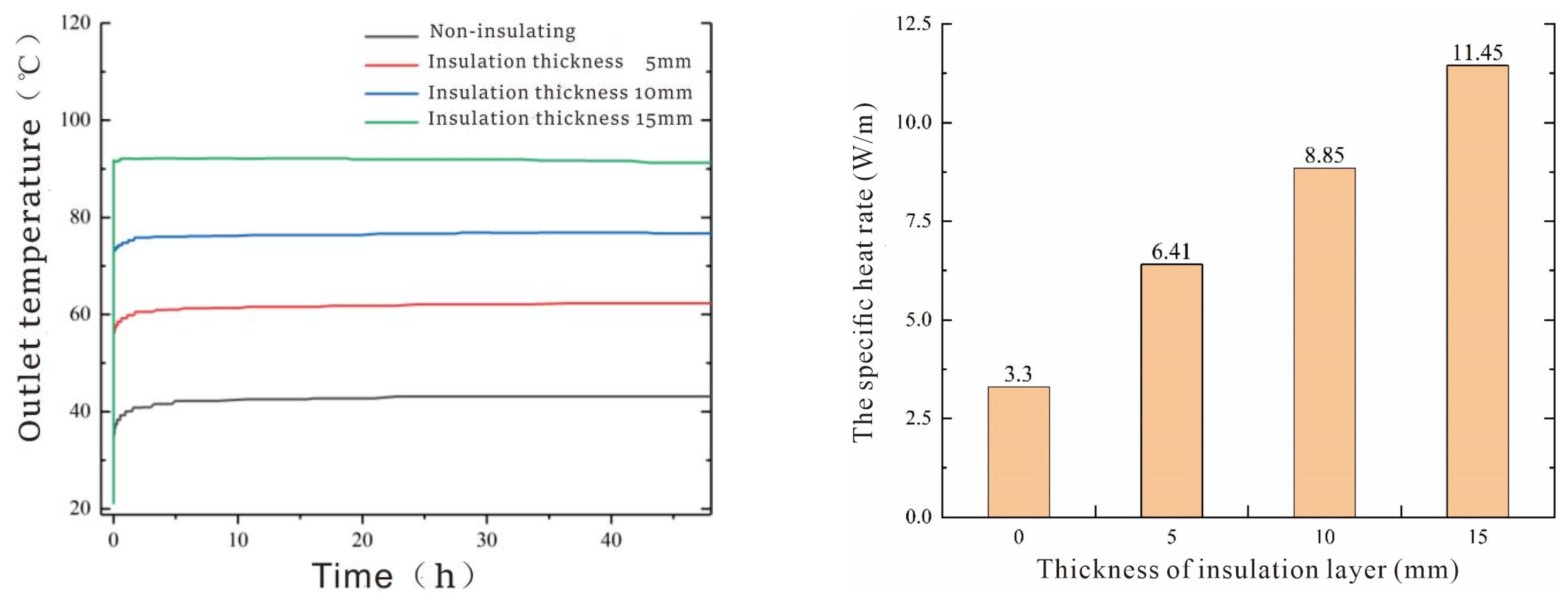
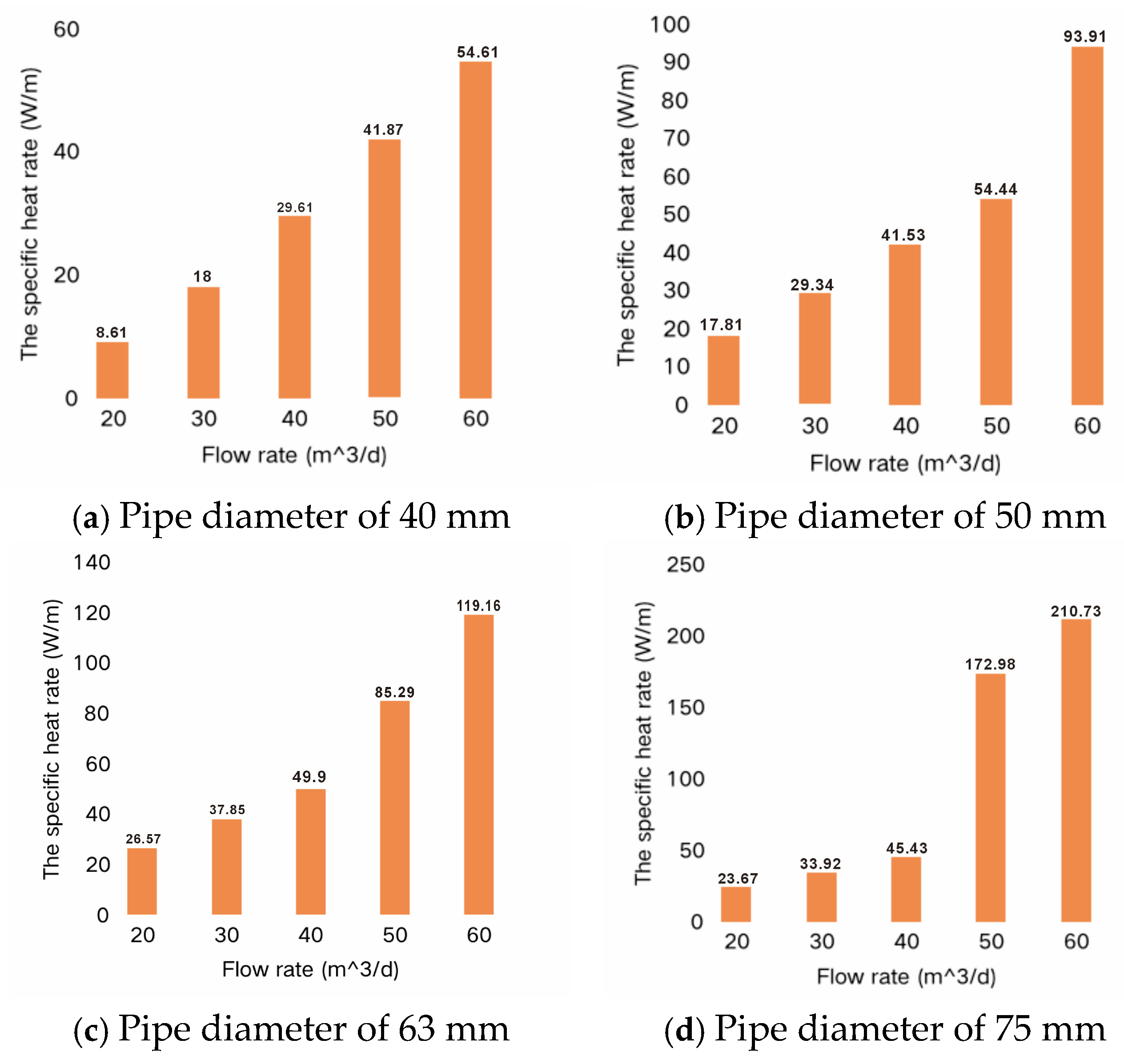
  • The effect of pipe insulation on the heat transfer efficiency of the GHE system in the HDR well was simulated. The results show that with a continuous operation for 48 h, the heat transfer pipe’s outlet temperatures for the insulation thicknesses of 0 mm, 5 mm, 10 mm, and 15 mm were 43.15 °C, 62.34 °C, 76.71 °C, and 91.26 °C, respectively. The specific heat rates were calculated to be 3.3 W/m, 6.41 W/m, 8.85 W/m, and 11.45 W/m, indicating that increasing the insulation thickness increased the specific heat rate by 94.24%, 126.32% 168.18%, and 246.97%, respectively. This demonstrates the significant impact of pipe insulation on the thermal extraction performance of the system. Further simulation indicated that enlarging the pipe diameter and fluid flow rate can achieve a higher thermal performance of the ground heat exchanger.
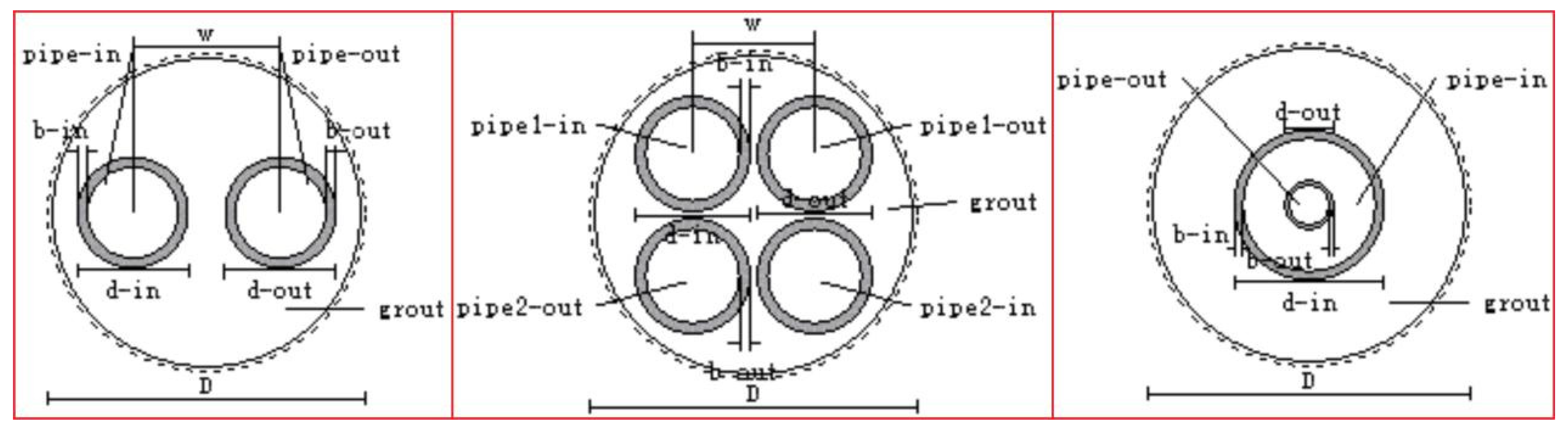
  • Three types of ground heat exchangers (GHE), including single U-shaped, double U-shaped, and coaxial pipes, were numerically investigated. The maximum possible pipe diameters for these configurations were 75 mm for single U-shaped pipes, 63 mm for double U-shaped pipes, and 178 mm for coaxial pipes. The results indicated that the heat exchange efficiency of the single U-shaped and double U-shaped configurations was slightly lower than that of the coaxial pipe. For the single U-shaped type with a 75 mm buried pipe diameter and a flow rate of 300 m3/d, the best heat transfer effect was 273.73 W/m. The double U-shaped type, constrained by the borehole size, could only accommodate a maximum buried pipe diameter of 63 mm, with the best heat transfer effect of 341.33 W/m at the same flow rate of 300 m3/d. For the coaxial type, with an outer diameter of 178 mm and an inner diameter of 110 mm, the best heat transfer effect was 315.93 W/m at a flow rate of 600 m3/d.
This study provides scientific and technical support for the development of HDR geothermal resources. By optimizing pipe configurations and insulation measures, geothermal energy extraction efficiency can be significantly improved, reducing development costs and promoting practical application.

Author Contributions

Methodology, Y.H. and L.D.; Software, Y.H., L.T. and J.L.; Validation, Q.Z. and J.L.; Formal analysis, F.L., L.T., J.L. and L.D.; Investigation, L.T.; Data curation, Q.Z.; Writing—original draft, Q.Z. and F.L.; Writing—review & editing, F.L. All authors have read and agreed to the published version of the manuscript.

Funding

This research was founded by Key Research and Development Program of Qinghai province, China (No. 2021-SF-132); Research on Heat Exchange of Medium-Deep Geothermal Resources in Hehuang New District of Qinghai Province, (Bureau of Geology and Mineral Exploration and Development of Qinghai Province, [2024] Document No. 37 & [2025] Document No. 09); Research Design for Target Area Optimization and Development Utilization of Geothermal Resources in Key Towns of Southern Qinghai province, (Bureau of Geology and Mineral Exploration and Development of Qinghai Province [2025] Document No. 09)).

Data Availability Statement

The original contributions presented in the study are included in the article, further inquiries can be directed to the corresponding author.

Conflicts of Interest

The authors declare no conflict of interest.

References

  1. Tang, X.; Cheng, L.; Xu, W. Numerical study on factors that influence the heat transfer performance of mid-deep coaxial casing heat exchanger in the Xi.an area. Chin. J. Geol. (Sci. Geol. Sin.) 2021, 56, 985–999. [Google Scholar] [CrossRef]
  2. Liu, M.; Rehman, S.; Tang, X.; Gu, K.; Fan, Q.; Chen, D.; Ma, W. Methodologies for Improving HDR Efficiency. Front. Genet. 2019, 9, 691. [Google Scholar] [CrossRef] [PubMed]
  3. Pan, S.; Kong, Y.; Chen, C.; Pang, Z.; Wang, J. Optimization of the utilization of deep borehole heat exchangers. Geotherm. Energy 2020, 8, 6. [Google Scholar] [CrossRef]
  4. Liu, J.; Wang, F.; Cai, W.; Wang, Z.; Li, C. Numerical investigation on the effects of geological parameters and layered subsurface on the thermal performance of medium-deep borehole heat exchanger. Renew Energy 2020, 149, 384–399. [Google Scholar] [CrossRef]
  5. Deng, J.; Wei, Q.; Liang, M.; He, S.; Zhang, H. Field test on energy performance of medium-depth geothermal heat pump systems (MD-GHPs). Energy Build. 2019, 184, 289–299. [Google Scholar] [CrossRef]
  6. Zhang, S.; Liu, J.; Zhang, X.; Niu, D.; Wang, F.; Chai, J.; Lu, Y.; Sun, Y.; Lin, Z. Effects of climate change on long-term building heating performance of medium-deep borehole heat exchanger coupled heat pump. Energy Build. 2023, 293, 113208. [Google Scholar] [CrossRef]
  7. Song, X.; Wang, G.; Shi, Y.; Li, R.; Xu, Z.; Zheng, R.; Wang, Y.; Li, J. Numerical analysis of heat extraction performance of a deep coaxial borehole heat exchanger geothermal system. Energy 2018, 164, 1298–1310. [Google Scholar] [CrossRef]
  8. Holmberg, H.; Acuña, J.; Næss, E.; Sønju, O.K. Thermal evaluation of coaxial deep borehole heat exchangers. Renew Energy 2016, 97, 65–76. [Google Scholar] [CrossRef]
  9. Kolo, I.; Brown, C.S.; Nibbs, W.; Cai, W.; Falcone, G.; Nagel, T.; Chen, C. A comprehensive review of deep borehole heat exchangers (DBHEs): Subsurface modelling studies and applications. Geotherm. Energy 2024, 12, 19. [Google Scholar] [CrossRef]
  10. Le Lous, M.; Larroque, F.; Dupuy, A.; Moignard, A. Thermal performance of a deep borehole heat exchanger: Insights from a synthetic coupled heat and flow model. Geothermics 2015, 57, 157–172. [Google Scholar] [CrossRef]
  11. Niu, Q.; Ma, K.; Wang, W.; Pan, J.; Wang, Q.; Du, Z.; Wang, Z.; Yuan, W.; Zheng, Y.; Shangguan, S.; et al. Multifactor analysis of heat extraction performance of coaxial heat exchanger applied to hot dry rock resources exploration: A case study in matouying uplift, Tangshan, China. Energy 2023, 282, 128277. [Google Scholar] [CrossRef]
  12. Wang, C.; Fang, H.; Wang, X.; Lu, J.; Sun, Y. Study on the influence of borehole heat capacity on deep coaxial borehole heat exchanger. Sustainability 2022, 14, 2043. [Google Scholar] [CrossRef]
  13. Zhao, Y.; Ma, Z.; Pang, Z. A Fast Simulation Approach to the Thermal Recovery Characteristics of Deep Borehole Heat Exchanger after Heat Extraction. Sustainability 2020, 12, 2021. [Google Scholar] [CrossRef]
  14. Li, Y.; Xu, S.; Zhang, W.; Sun, Y.; Han, Y.; Zhang, H.; Huang, J. Thermal short-circuiting and heat transfer performance of coaxial borehole heat exchanger. Coal Geol. Explor. 2020, 48, 183–188. [Google Scholar] [CrossRef]
  15. Bao, X. Study on Heat Transfer Characteristics of the Middle-Deep Coaxial Casing Ground Heat Exchanger; Hebei University of Engineering: Handan, China, 2020. [Google Scholar] [CrossRef]
  16. Fang, L.; Diao, N.; Shao, Z.; Wang, Z.; Fang, Z. Study on Thermal Resistance of Coaxial Tube Boreholes in Ground-Coupled Heat Pump Systems. Procedia Eng. 2017, 205, 3735–3742. [Google Scholar] [CrossRef]
  17. Fang, L.; Diao, N.; Shao, Z.; Zhu, K.; Fang, Z. A computationally efficient numerical model for heat transfer simulation of deep borehole heat exchangers. Energy Build. 2018, 167, 79–88. [Google Scholar] [CrossRef]
  18. Liu, Z.; Xu, W.; Qian, C.; Chen, X.; Jin, G. Investigation on the feasibility and performance of ground source heat pump (GSHP) in three cities in cold climate zone, China. Renew Energy 2015, 84, 89–96. [Google Scholar] [CrossRef]
  19. Wu, T.; Liu, Y.; Dong, Z.; Fang, Y.; Liu, Y. Research and application of ground source heat pump refrigeration. Chin. J. Refrig. Technol. 2014, 4, 71–75. [Google Scholar] [CrossRef]
  20. Wu, W.; Skye, H.M. Progress in ground-source heat pumps using natural refrigerants. Int. J. Refrig. 2018, 92, 70–85. [Google Scholar] [CrossRef]
  21. Ahmadi, M.H.; Ahmadi, M.A.; Sadaghiani, M.S.; Ghazvini, M.; Shahriar, S.; Alhuyi Nazari, M. Ground source heat pump carbon emissions and ground-source heat pump systems for heating and cooling of buildings: A review. Environ. Prog. Sustain. Energy 2018, 37, 1241–1265. [Google Scholar] [CrossRef]
  22. Brown, C.S.; Kolo, I.; Falcone, G.; Banks, D. Investigating scalability of deep borehole heat exchangers: Numerical modelling of arrays with varied modes of operation. Renew Energy 2023, 202, 442–452. [Google Scholar] [CrossRef]
  23. Chen, C.; Shao, H.; Naumov, D.; Kong, Y.; Tu, K.; Kolditz, O. Numerical investigation on the performance, sustainability, and efficiency of the deep borehole heat exchanger system for building heating. Geotherm. Energy 2019, 7, 18. [Google Scholar] [CrossRef]
  24. Cheng, N.; Zhou, C.; Luo, Y.; Shen, J.; Tian, Z.; Sun, D.; Fan, J.; Zhang, L.; Deng, J.; Rosen, M.A. Thermal behavior and performance of shallow-deep-mixed borehole heat exchanger array for sustainable building cooling and heating. Energy Build. 2023, 291, 113108. [Google Scholar] [CrossRef]
  25. Manzoor, A.; Saghir, M. Heat transfer enhancement in multiple pipes configuration using different fluid mixtures: A numerical approach. Int. J. Thermofluids 2021, 10, 100088. [Google Scholar] [CrossRef]
  26. Zhang, J.; Li, Y.; Li, L.; Lu, X.; Zhang, W.; Tang, C.; Kong, X. An integrated system combining MDBHE (multi-casing DBHE) and heat pump achieves heating and cooling for medium-deep geothermal energy utilization. Energy 2024, 295, 131061. [Google Scholar] [CrossRef]
  27. Luo, Y.; Xu, G.; Zhang, S.; Cheng, N.; Tian, Z.; Yu, J. Heat extraction and recover of deep borehole heat exchanger: Negotiating with intermittent operation mode under complex geological conditions. Energy 2022, 241, 122510. [Google Scholar] [CrossRef]
Figure 1. The study area is located in the Gonghe Basin, Qinghai Province, China.
Energies 18 02229 g001
Figure 2. The columnar strata of drillhole cores of dry heat rock bodies in the study area.
Energies 18 02229 g002
Figure 3. Schematic diagram of the heat transfer test device and the test setup.
Energies 18 02229 g003
Figure 4. Components of the field heat transfer test apparatus. (a) The testing pipe, (b) Tube for heat exchange in the bottom of the DBHE, (c) A shapshot of the testing device on the ground surface.
Energies 18 02229 g004
Figure 5. Modeling of the initial conditions of ground temperature.
Energies 18 02229 g005
Figure 6. Three types of ground heat exchangers: single U-shaped in the left sub-Figure, double U-shaped in the middle, and coaxial in the right sub-Figure.
Energies 18 02229 g006
Figure 7. Schematic diagram of the discrete model for the three types of GHEs.
Energies 18 02229 g007
Figure 8. Borehole temperature distribution curves at different flow rates (50 mm diameter).
Energies 18 02229 g008
Figure 9. Fluid outlet temperature of a GHE under different heat insulation conditions.
Energies 18 02229 g009
Figure 10. Heat transfer efficiency under different flow rates.
Energies 18 02229 g010
Table 1. The material properties and configuration parameters of the heat exchanger pipe.
Property and ConfigurationArgumentUnit
Hole diameter (D)215mm
Inlet and outlet pipeVertical heat exchanger(-)
Buried pipe’s diameter (d)10mm
Buried pipe’s depth (H)3102m
Heat exchanger (w)100mm
Heat exchanger tube thickness (b)3mm
Heat exchanger’s thermal conductivity350W/(m·K)
Table 2. The setup for the pipe insulation in the numerical model.
No.Pipe Diameter (mm)Insulation Thickness
(mm)
External
Diameter
Internal Diameter
11060
22065
330610
440615
Table 3. The modeling setup and parameters input for the numerical models.
Pipe TypeModel SizeAperture
(mm)
Heat Exchanger Pipe Diameter (Outside Diameter), mmTube Spacing, wPipe’s Thermal Conductivity,
W/(m·K)
Platform File
Single U-shaped1000 m × 1000 m
× 3200 m
21532/40/50/63/7580 mmUninsulated: 42
Thermal insulation: 0.042
Single-U FEM platform.fem
Double U-shaped32/40/50/63/7580 mmDouble-U FEM platform.fem
CoaxialInner pipe: 32/40/50/63
Outer pipe: 40/50/63/75
-Coaxial FEM platform.fem
Table 4. Comparison of the heat transfer performance of three types of GHEs.
Flow Rate (m3/d)
Type of the Buried Pipe
405060180240300600
Single U-shaped pipe (75 mm) heat transfer (W/m)27.438.561.3171.9210.7274.0-
Double U-shaped pipe (63 mm) heat transfer (W/m)33.648.176.6214.8263.4341.3-
Coaxial pipe (inner diameter of 110 mm, outer diameter of 178 mm) heat transfer (W/m)----273.5225.6315.9
Disclaimer/Publisher’s Note: The statements, opinions and data contained in all publications are solely those of the individual author(s) and contributor(s) and not of MDPI and/or the editor(s). MDPI and/or the editor(s) disclaim responsibility for any injury to people or property resulting from any ideas, methods, instructions or products referred to in the content.

