Abstract
The dual three-phase permanent magnet synchronous motor (DT-PMSM) has the advantages of high fault tolerance, flexible control, small torque ripple, and meeting the requirements of low voltage and high power. However, in the traditional model of predictive torque control (MPTC) of DT-PMSM, the calculation is cumbersome due to the numerous voltage vectors. Therefore, a fast-switching table based on torque prediction DT-PMSM control is established. In addition, in the DT-PMSM conventional MPTC strategy, the cost function consists of the electromagnetic torque error and the stator flux error. Due to the lack of an explicit theory to guide the design of the weight coefficients, the weight coefficients can only be set through a large number of simulations and experiments in applications, and the tuning process is very cumbersome. Therefore, the support vector machine regression (SVR) method was used to improve the tedious calculation and tuning process of MPTC of DT-PMSM. The experimental results show that MPTC based on a fast-switching table achieves good steady-state and dynamic control performance by using weighting factors.
1. Introduction
Due to the technical cost limitations of three-phase PMSM drive systems at medium and high voltage levels and in high-power applications, public attention has gradually turned to the DT-PMSM system, which plays an important role in scenarios requiring high power and high reliability [1,2,3]. Based on DT-PMSM, vector control [4] and direct torque control [5] are used and compared. MPTC can predict the future state of variables more intuitively and optimize the output more effectively. The MPTC method helps achieve smoother PMSM speed and suppresses torque ripple [6]. The control method with an adaptive observer and position prediction provides high performance and robustness for PMSM control [7,8,9].
The advantages of MPTC have aroused extensive research by many scholars. Ref. [10] proposed a dual vector combined control, which added a zero-voltage vector to improve the performance of PMSM torque control during the prediction process. Ref. [11] proposed a zero-vector expansion selection, which is a generalized bidirectional control method, in order to obtain a better control effect. Ref. [12] proposed a load observer combined with a feed-forward compensation method, which can compensate based on the observed load torque results to improve robustness and dynamic response. Ref. [13] found that adding delay compensation in the control process reduces the dynamic response problem caused by a large amount of calculations. All references [12,13] are aimed at the study of three-vector control. All the above literature can improve the dynamic control performance and anti-interference of PMSM. However, the impact of increasing the amount of calculation is inevitable. It makes the prediction process more complex, and the overall calculation is large. In the face of more characteristics of the DT-PMSM voltage vector, the disadvantages will be amplified. Sector subdivision is a direction of intensive research today. Ref. [14] subdivides the sector into 12 and uses 6 basic voltage vectors to compose 6 virtual voltage vectors. The 12 effective voltages further reduce the torque ripple. Ref. [15] uses the torque lag method to select the candidate voltage vectors, which quickly selects from the 12 voltage vectors and better reduces the computational burden. But, it suffers from torque errors. In order to solve the problem of 13-times prediction in a control cycle after subdividing the sector and increasing the amount of calculation, Ref. [16] proposes a fast-switching prediction table. The voltage vector effect is divided into four categories by using the idea of direct torque control, and the choice of prediction is reduced, so as to solve the problem of calculation cost. However, the above methods have not been applied to DT-PMSM.
During motor operation, parameter variations under complex dynamic conditions degrade the control performance when fixed weighting coefficients are used in model-predictive torque control (MPTC). This limitation has driven substantial research on adaptive weight optimization strategies to maintain robustness. Ref. [17] proposed a double-cost function method, which sorted the torque error and flux error, respectively, took the average of the serial number, and selected the voltage vector that could minimize the average value. Ref. [18] proposed an MTPC method based on a logical operation. The various parameters in the cost function are sorted and summed, and then, the voltage vector that minimizes is selected. Ref. [19] proposed a method of an unweighted coefficient for induction motor MPTC, which can transform the cost function into a stator flux vector according to the relationship between electromagnetic torque and flux amplitude and improve the control performance. Ref. [20] not only proposed to set the torque and flux double-cost function but also introduced the penalty term. In the double-cost function double-process real-time calculation, the algorithm can select the optimal voltage vector and has better robustness. The above methods eliminate the weight coefficients but ignore the error of the parameters and the complex dimension problem. Ref. [16] proposes a method of a PI controller to dynamically adjust the weight coefficient. The actual torque is different from the given torque, and the appropriate weight coefficient is output after the PI controller and limiter. However, in the face of complex working conditions, the improvement effect of the steady-state and dynamic performance of the motor is not good. Ref. [21] proposes a simple transfer reinforcement learning method, which enables the power grid following the converter to convert between different system parameters and has strong adaptability. Ref. [22] proposes a deep-transfer reinforcement learning method based on physical information and an intensively trained deep reinforcement learning enabled (ISOP-DAB) converter to achieve power balance control. The reinforcement learning method used in the above two articles in the field of converters has the advantages of high data efficiency and strong generalization, and can be a good reference for thinking. However, there are complex modeling situations in DT-PMSM control.
Ref. [23] proposed an online weight factor tuning method for cascaded neural networks to establish data replacement models under various working conditions. However, the neural network cannot guarantee the global optimal solution and falls into the problem of local minimum [24]. In the field of motor control, SVR is applicable to scenarios with small samples and high interpretability. However, its limitations in high-dimensional dynamic system modeling and real-time performance have promoted the popularization of deep neural networks (DNNs).
2. Theoretical Model of DT-PMSM
Compared with conventional PMSM, the dual three-phase PMSM (DT-PMSM) exhibits higher-order dynamics, pronounced nonlinearities, and strong cross-coupling effects. To facilitate simulation and control-oriented analysis, coordinate transformation-based model order reduction techniques are applied. The following simplifications are implemented: (1) sinusoidal distribution of air-gap magnetomotive force (MMF) and flux density, (2) exclusion of magnetic saturation and core loss phenomena, and (3) negligible mutual leakage inductance between winding sets. The voltage equations in natural coordinates are formulated as [25]:
The flux linkage equation is
where us, is, ψs, and γ, respectively, are the stator-phase voltage matrix, stator-phase current matrix, stator flux matrix, rotor flux subdivision coefficient, and stator resistance. And they are represented as:
The electromagnetic torque of DT-PMSM is also shown as the sum of the electromagnetic torque generated by the two sets of three-phase windings, and the influence of the mutual inductance parameter is ignored in this paper. The electromagnetic torque equation under the double d-q transform is given and expressed as:
where np is the number of poles; ψd1, ψq1, ψd2, and ψq2 are the direct and cross-axis flux links of the two sets of windings, respectively; id1, iq1, id2, and iq2 are the direct- and cross-axis currents of the two sets of windings, respectively.
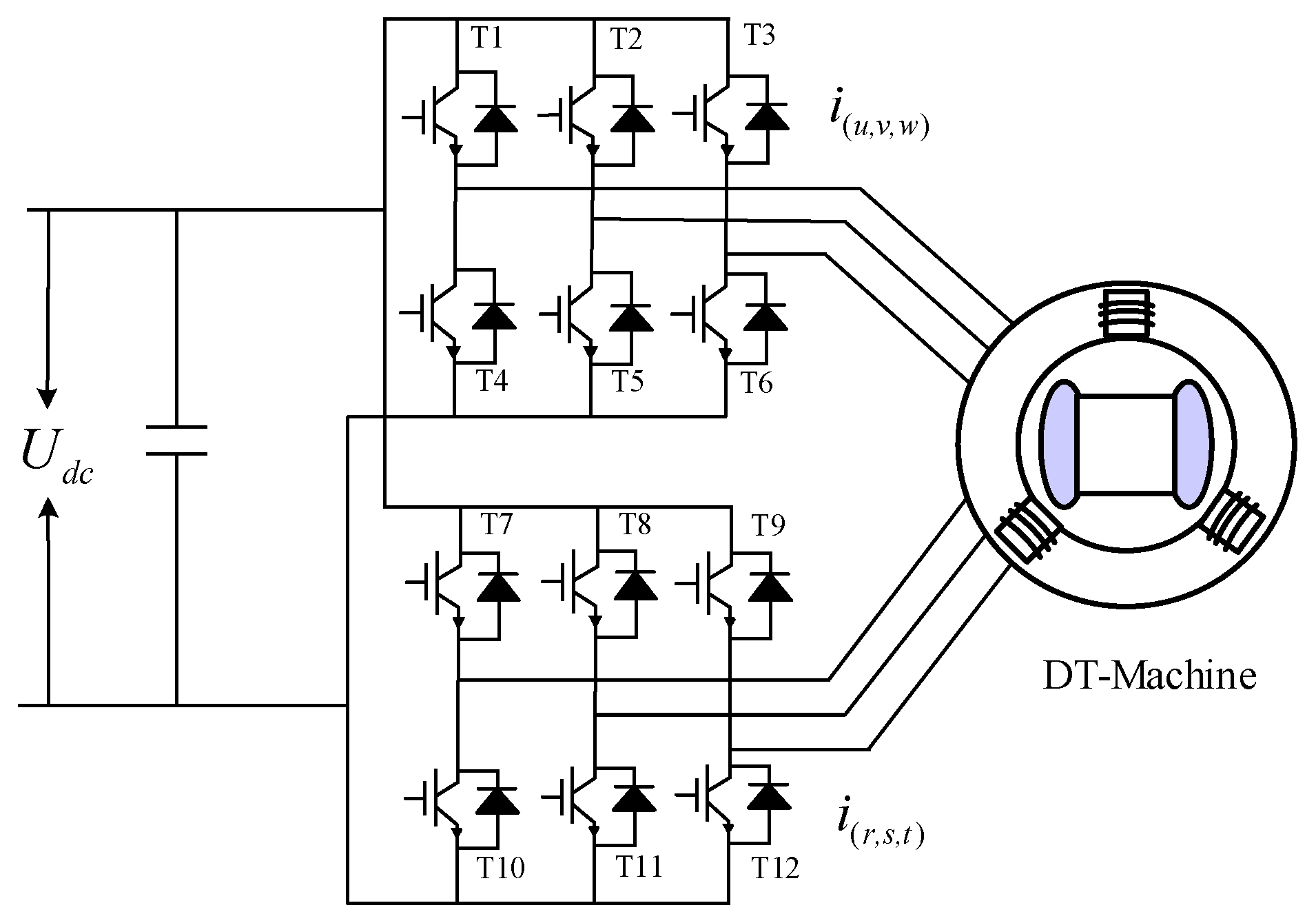
The model-predictive torque control (MPTC) strategy for three-phase permanent magnet synchronous motors (PMSMs) is realized through a three-phase voltage-source inverter (VSI) driving the PMSM, and predicts the basic switching state of the power device composition in real time to obtain the predicted torque and predicted flux. Then, the optimal voltage vectors and corresponding switching states are determined through cost function minimization, enabling precise torque and flux control, so as to obtain the appropriate inverter output state. As shown in Figure 1 below, this paper studies the MPTC method of DT-PMSM (the interleaved angle of each three-phase winding is zero, and the basic switching state is similar.
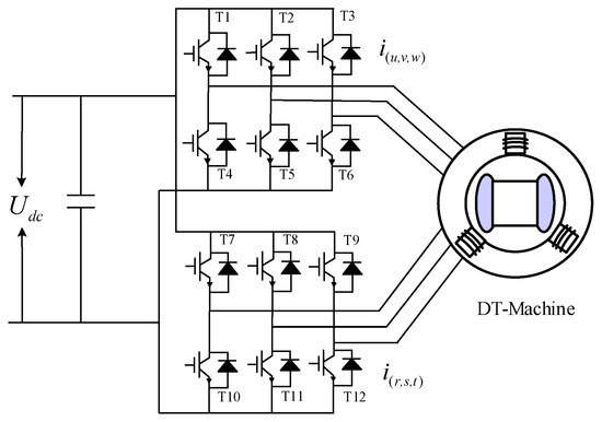
Figure 1.
Topology of dual three-phase motor voltage source-type inverter.
In the DT-PMSM system, when the power-switching signal is Tu = 1, the upper bridge arm of the u phase is switched on. Similarly, when Tu = 0, the lower bridge arm is a circuit breaker. Therefore, the phase voltage can be expressed as follows:
The voltage equation for complete space vector decoupling is as follows:
The differential form of the current can be further obtained as follows:
In order to predict the current at the next moment, the forward Euler discretization of Equation (7) can be obtained as follows:
The flux discrete prediction value and the torque discrete prediction value are as follows:
where the superscript “p” stands for the predicted value. Since the d-q inductance values of the surface-mounted PMSM are equal, and the basic voltage vector is selected according to the principle of cost function optimality, the cost function can be expressed as follows:
where Te* is the given value of electromagnetic torque, ψdq* is the given value of flux in the d-q coordinate system, ψxy* is the given value of flux in the x-y subspace, λ1 and λ2 are the weighting factors that constrain the d-q coordinate system and the x-y plane flux linkage, respectively.
In MPTC, the weight coefficients in the cost function are extremely difficult to tune. Most scholars use the empirical trial-and-error method or choose │ψdq*/Te*│ to unify the torque and flux.
In model-predictive control (MPC), the selection of weight coefficients directly affects the balance of multi-objective optimization, and dynamic response, torque pulsation, and THD are weighed by a systematic approach. The following are detailed steps and examples for parameter selection and optimization:
- dynamic characteristics (such as current/speed tracking) need to respond quickly to load changes or reference instructions;
- torque pulsation suppression reduces the mechanical vibration of the motor and improves running stability;
- THD reduction optimizes the power quality and reduces harmonic loss.
3. Simplify the Switch Table Strategy
In the vector control strategy, the number of voltage vectors of DT-PMSM is much larger than that of three-phase PMSM. The finite-set model prediction selects the best switching state by traversing the voltage vector, and in the actual control of the motor, if all the voltage vectors are applied, it will undoubtedly increase the computational burden of the control board. In order to simplify the prediction process of the MPC and improve the control effect, the sector division is introduced. Subdivide the sectors every 30° and synthesize a new vector by taking two adjacent basic voltage vectors.
The resultant voltage vector is as follows.
The new resultant voltage vector can be expressed as:
As shown in Figure 2, six new vectors are synthesized from six basic vectors and zero vector voltage vectors. U0 and U13 are zero-voltage vectors. The amplitude of the resultant voltage vector is smaller than that of the basic voltage vector due to the presence of a zero voltage vector joining. Therefore, using 14 voltage vectors for prediction will directly increase the prediction time and may cause the control performance to deteriorate
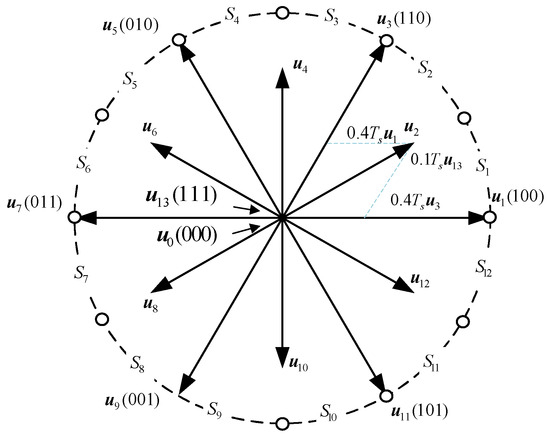
Figure 2.
Synthesis of voltage vectors.
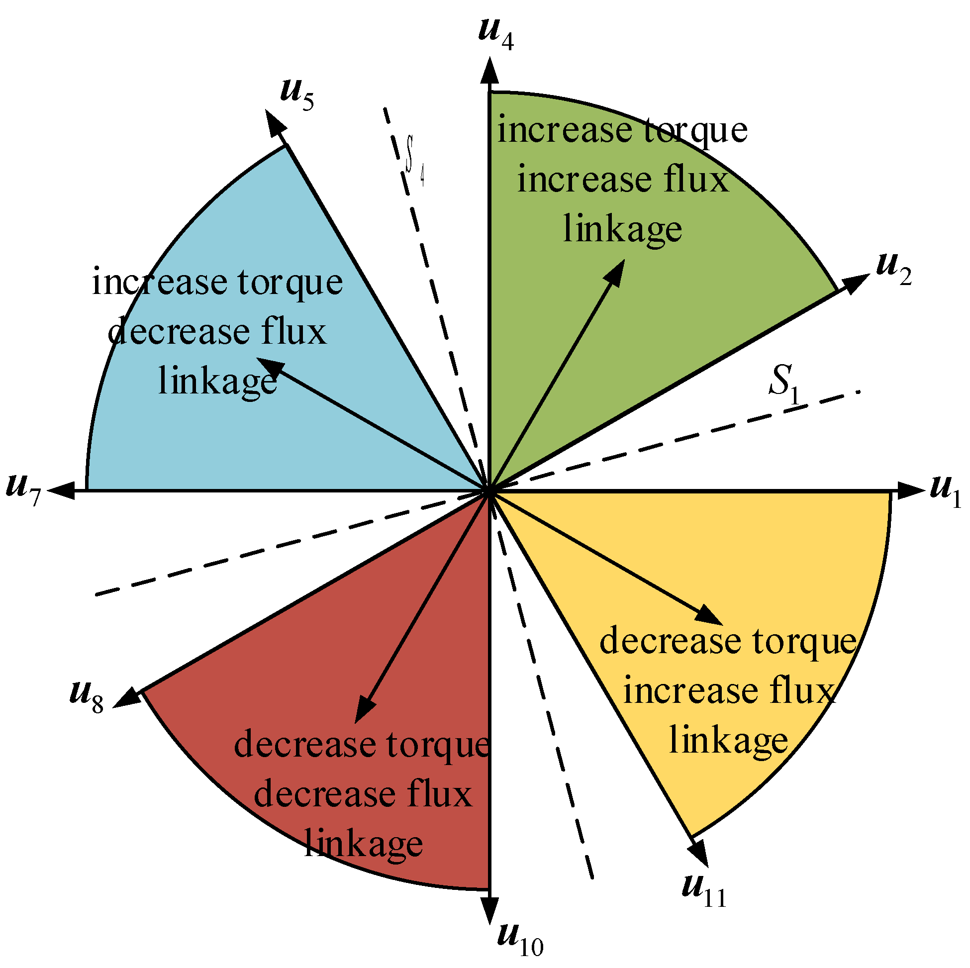
The calculation of MPTC in DT-PMSM is huge. In order to reduce the calculation, a fast prediction handoff table based on sector division is proposed. As shown in Figure 3, this method refers to direct torque control and classifies all non-zero voltage vectors into four types: both torque and flux increase, torque decreases while flux increases, flux increases while torque decreases, and both torque and flux decrease.

Figure 3.
Torque effect analysis within one cycle.
According to the angle range between the voltage vector and the flux vector (DTC idea), the voltage vectors can be divided into four categories: the angle from 0° to 90° increases the torque and increases the stator flux, from 90° to 180° increases the torque and decreases the stator flux, from 180° to 270° decreases the torque and decreases the stator flux, and from 270° to 360° decreases the torque and increases the stator flux.
For SPMSM, the incremental form of electromagnetic torque can also be expressed as:
According to Equation (12), the electromagnetic torque dynamics are governed by the stator flux linkage amplitude variation and angular displacement. The maximum torque increment is achieved when the stator voltage vector leads the flux linkage vector by 90°, whereas a −90°phase lag induces maximal torque decrement, as established in [16]. In sector S1, the vector selection strategy is analytically determined:
- U2 (assigned to the torque enhancement/flux augmentation zone);
- U7 (positioned in the torque-boosting/flux suppression region);
- U8 (allocated to the torque-diminishing/flux reduction sector);
- U1 (residing in the torque attenuation/flux amplification quadrant).
This systematic vector selection framework effectively mitigates steady-state torque pulsations through coordinated flux–torque decoupling control, while maintaining a rapid dynamic response. This method of selection greatly reduces the number of candidate voltage vectors for each sector, thus reducing the computational burden. Table 1 lists the steady-state fast predictive handoff methods for each sector.

Table 1.
The fast prediction switching table of each sector in steady state.
4. SVR Weight Coefficients Strategy
The weight coefficient is a very critical index in MPTC, and the choice of coefficient seriously affects the torque. The selection of weight coefficients is tedious and time-consuming, and it needs to be tuned by a large number of experiments. In order to improve this complex process and improve the steady-state performance, this paper proposes an SVR weight coefficient training method, which uses the weight factors and the corresponding transformer parameters under a specific working condition to train the data replacement model under the specific working condition and determines the fitness function to obtain the best weight factor.
Ref. [16] shows the dynamic adjustment weight coefficient based on PI, as shown in Figure 4 as shown.
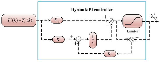
Figure 4.
The weight coefficient PI controller.
The system estimates the current torque according to Equation (9) and calculates the deviation from the set torque. Through the proportional–integral controller and limiter processing, the appropriate weight coefficient is obtained.
The adjustment rule of the weight coefficient is that, if the dynamic response is slow, the coefficient should be increased. If the torque ripple is large, the coefficient should be increased. If THD is high, the coefficient should be increased. In this paper, the SVR method is used to detect the load state based on condition recognition and switch the preset weight coefficient group.
The original weight coefficient design system is considered a nonlinear system with a single input and output. Te(err), [id, iq, ψs], and λ1,2 are the input, state, and output variables, respectively. The training samples of the data replacement model are set to T = {(xi, yi), i = 1, …, k} ∈ RN × R, where xi is the input sample containing three features (id, id, iq, and ψs), and the feature λ1,2 is contained in the output sample yi. And the SVR function model can be viewed as a hyperplane in kernel space, as follows:
where θ is the weight vector of the hyperplane f(x), h is the bias term, and p(x) denotes the mapping of the data RN to the high-dimensional feature space H. The optimization marginal condition of the SVR model is expressed as follows:
where 1/2‖θ‖2 is the minimum marginal risk condition, and the additive term on the right-hand side is the minimum sample error. Two nonnegative variables τi and τi* are used to reduce the constraint on some sample points. C is a compromise between the marginal risk and the sample error. The restriction is expressed as follows:
In Equation (15), ε is the insensitive coefficient, which is used to avoid overfitting. To solve Equation (14), the above optimization problem is reformulated as a Lagrange function, and the Lagrange multipliers αi, αi* ≥ 0 and ηi, ηi* ≥ 0 are introduced. The expression is as follows:
The Gaussian kernel function satisfying Mercer’s condition is selected to replace the inner product of the high-dimensional kernel space in Equation (16). The kernel function can be expressed as follows:
The optimization condition can be further expressed as follows:
The above constraints are expressed as follows:
In (18), the partial coefficients (αi − αi*) are not zero. The samples (xi, yi) corresponding to nonzero (αi − αi*) are support vectors. The SVR-based optimization Equation (13) is expressed as follows:
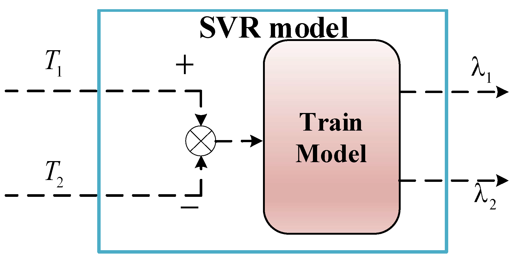
Therefore, the SVR-based alternative model can be expressed as (Figure 5):
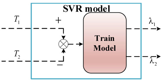
Figure 5.
SVR system modeling.
In Figure 5, the support vector regression (SVR) model is used to replace the original control logic model. The SVR system model no longer needs an accurate mathematical model and can quickly obtain the appropriate output value through the input value of the characteristic values after training. And it realizes the real-time adjustment of the weight factor under different working conditions.
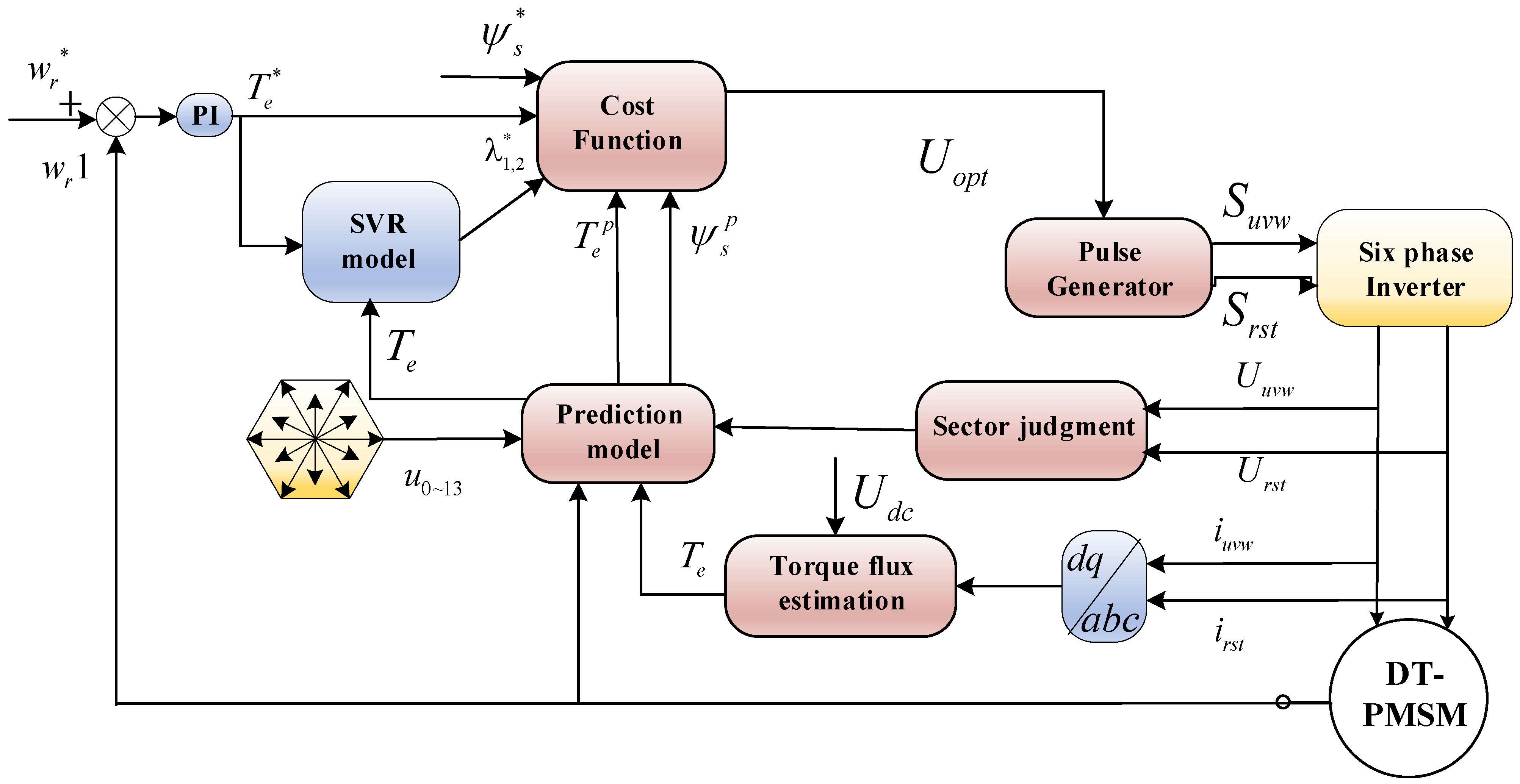
Figure 6 shows the MPTC control block diagram of the design system based on SVR weight coefficients. In Figure 6, the SVR model replaces the weight coefficient control link in the original MTPC system to form the SVR-MPTC system. Thus, the system optimizes the weighting factors for each condition offline using a data-driven approach to minimize the online computational burden.

Figure 6.
Schematic of SVR-MPTC based on fast switch table prediction.
5. Simulation Experiment
In order to confirm the effect of the proposed method, the Simulink simulation model of the SVR-MPTC algorithm system based on the fast-switching table is established, and the MPTC strategy with the traditional switch selection method and the weight coefficient design method is compared with the SVR-MPTC strategy based on the fast-switching table method. The simulation model was loaded into the RT-LAB (OP5600) experimental platform, and the hardware-in-the-loop system of the DT-PMSM drive system was realized. Figure 7 shows the logic and physical diagram of the experimental system platform, in which the core controller uses a DSP chip of the model TMS320F2812, and the main system structure, such as the inverter, is built by RT-LAB internal real-time simulation. The main parameters of the DT-PMSM are shown in Table 2.
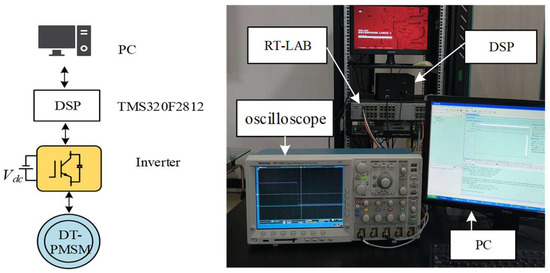
Figure 7.
RT-LAB semi-physical experiment platform.
Table 2.
The parameter table of the DT-PMSM.
The experimental group settings are as follows: (i) the MPTC method of the traditional DT-PMSM (MPTC), (ii) the MPTC with the traditional weight coefficient method with fast opening and closing tables (FS-MPTC), and (iii) the fast-switching table method MPTC using SVR weight coefficients (FSSVR-MPTC). In the experiment, the PI parameters of the velocity loop are the same for the three groups of control methods, and the stable value of the weight coefficient of the traditional MPTC and FC-MPTC is selected as 0.01818 in this paper. Through the experiments with the three groups of control methods, the dynamic performance, torque ripple characteristics, and harmonic content of the PMSM in the start-up phase and dynamic process are verified.
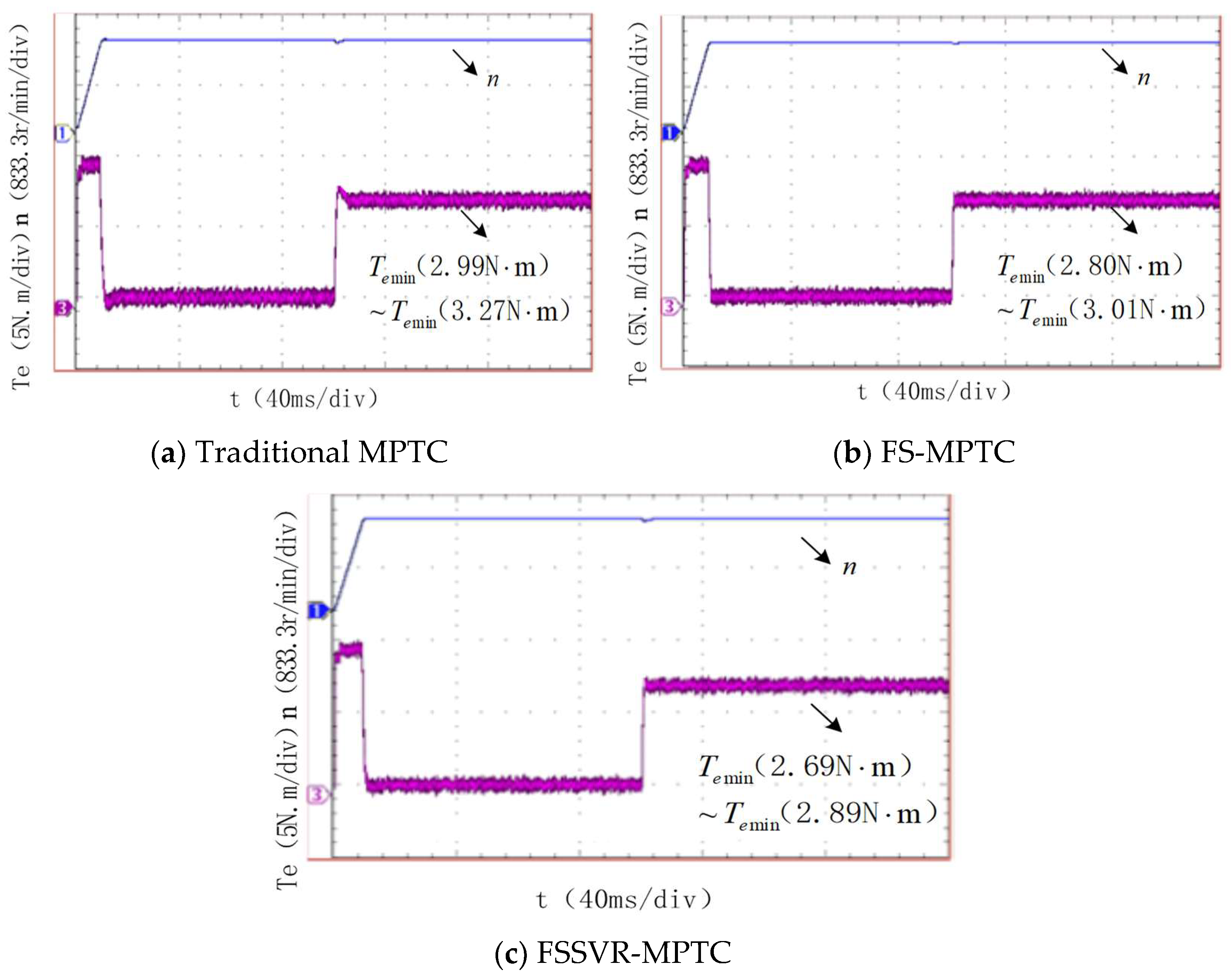
Figure 8 shows the dynamic speed and torque curves of a sudden load of 10 N.m at a speed of 1000 r/min and 0.1 s. From the dynamic response shown in Figure 8, it can be seen that, when the load changes suddenly, the three control strategies can achieve smooth and fast speed tracking, and the three groups of control strategies have almost no speed overshoot at no load. And the torque waveform of the three control methods in the PMSM variable load is compared. It can be seen that the sector division and weight coefficient design have an inhibitory effect on the torque ripple. In the steady state, the fluctuation range of the traditional MPTC is 2.99~3.27 N.m. The fluctuation range of FS-MPTC is 2.80~3.01 N.m. The torque fluctuation of FSSVR-MPTC ranges from 2.66 to 2.87 N.m. According to the data analysis, the reduction in torque ripple is due to the fast-switching table prediction and the accurate selection of the SVR online weight coefficients, which greatly reduces the calculation time and torque ripple of the proposed method compared with the traditional MPTC. Under the control of complex operating conditions, FSSVR-MPTC has stronger and better steady-state characteristics.
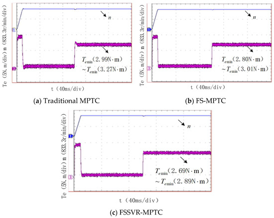
Figure 8.
Motor speed and stator current waveforms.
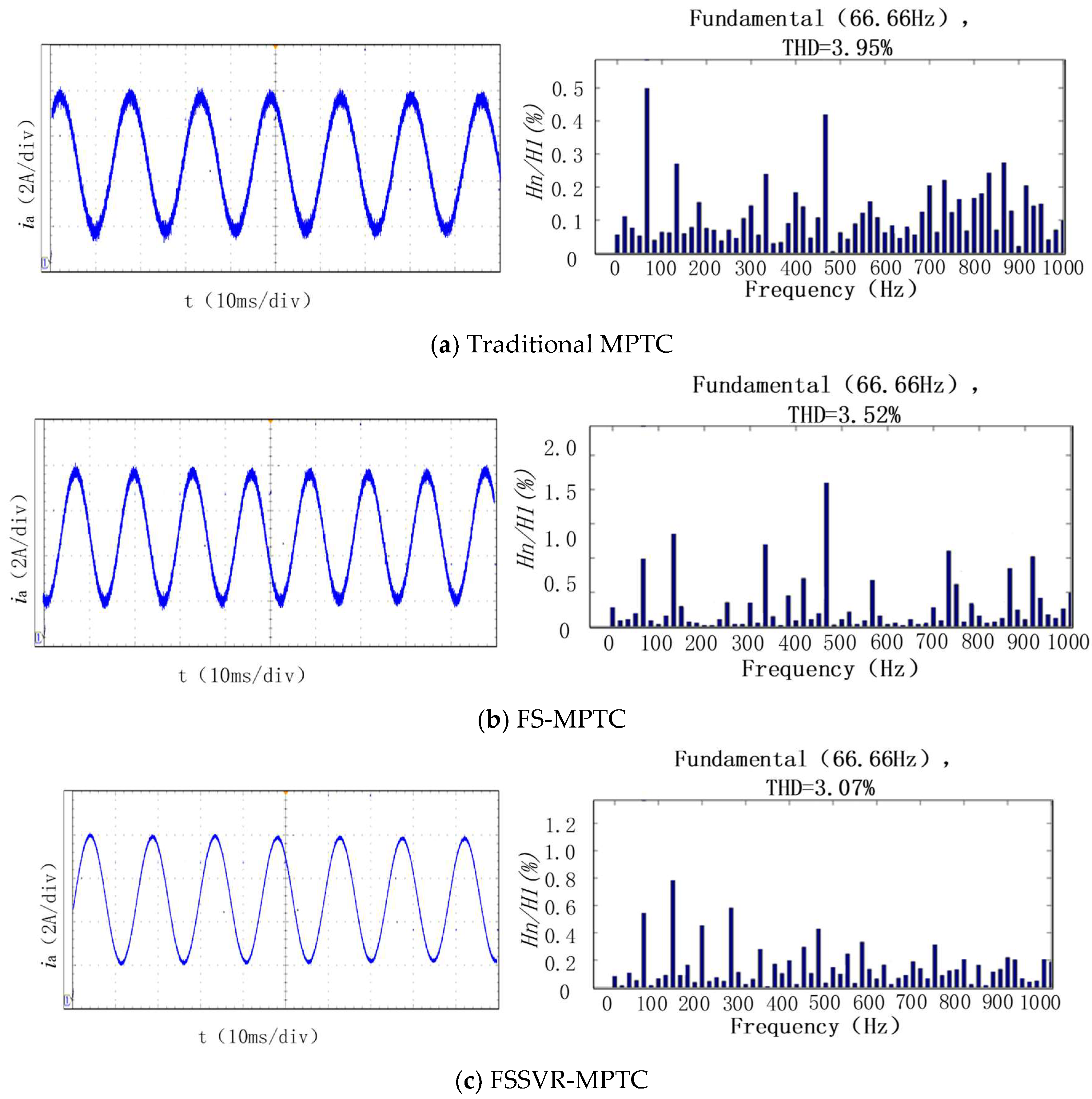
Figure 9 shows the phase current waveform and FFT analysis of the phase A current under the condition of loading 10 N.m in 0.1 s. The total harmonic distortions (THD) of the traditional MPTC, FS-MPTC, and FSSVR-MPTC are 3.95%, 3.52%, and 3.05%, respectively. Compared with the traditional MPTC, the THD of FS-MPTC is reduced by 10.08%, while that of the FSSVR-MPTC is reduced by 22%. The experimental results show that the FSSVR-MPTC can reduce the motor phase current distortion, reduce the harmonic content, and improve the waveform quality, so as to improve the control performance.
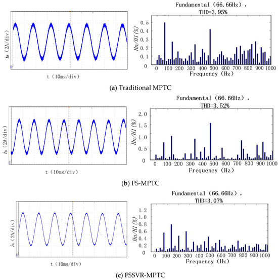
Figure 9.
Phase current ia waveform and FFT analysis.
The traditional MPTC strategy has no weight coefficient design, and the selected coefficient is not always the optimal solution in the face of complex operating conditions. Both FS-MPTC and FSSVR-MPTC have a weight coefficient design, which can better control the weight coefficient selection, resulting in a relatively high quality of the generated current and better control performance.
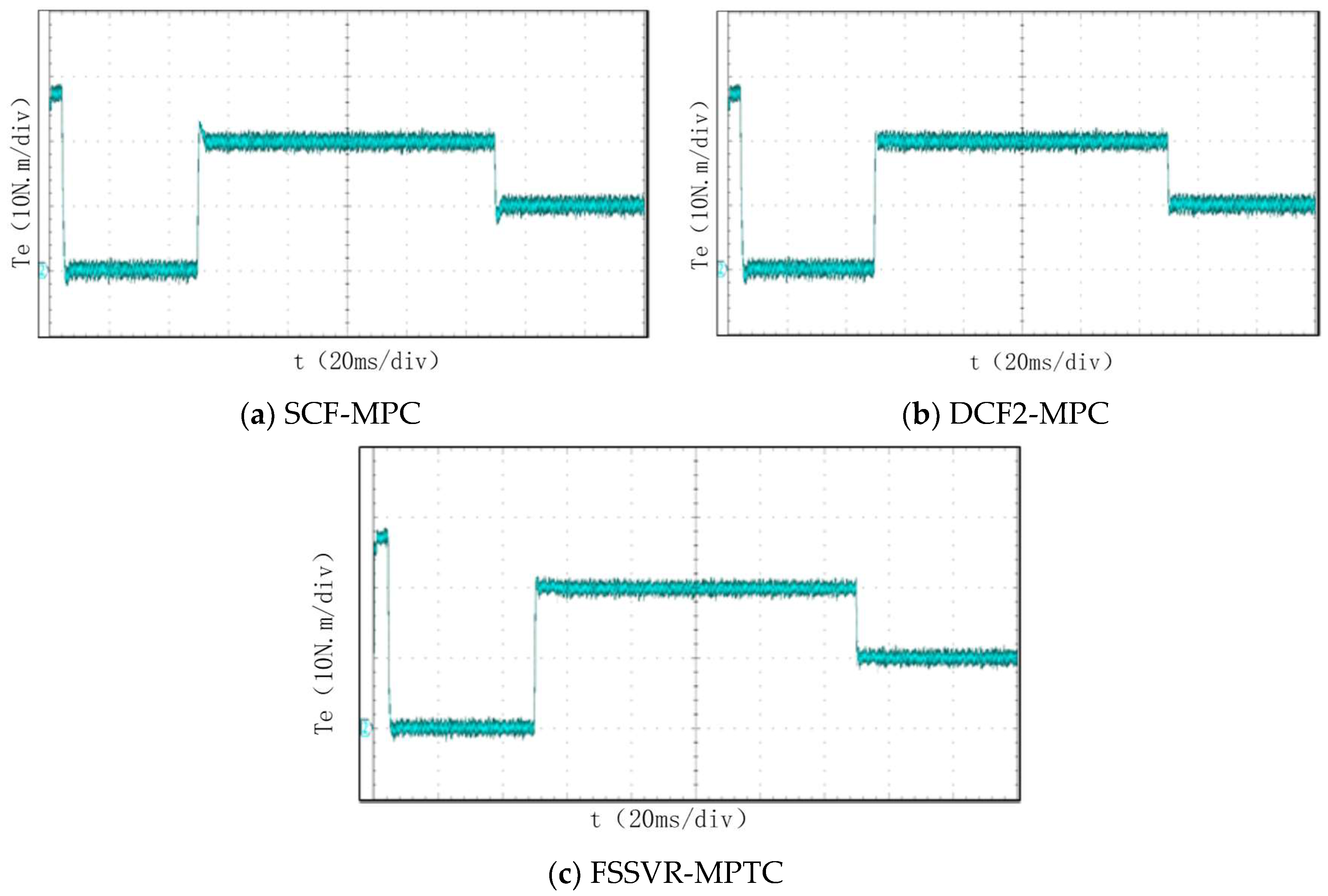
In order to verify the dynamic and steady-state performance of the three groups of control method under different operating conditions, the motor was set to load 20 N.m at 0.05 s. The load drops from 20 N.m to 10 N.m at 0.015 s. The motor torque Te variation curve is shown in Figure 10. The specific experimental data are shown in Table 3. Compared with the traditional MTPC, FS-MPTC has less time to reach the torque rating, and the torque jitter value is reduced by 15.72% during loading and 11.48% during unloading. The torque ripple is reduced by 10.7%. It can be seen that the FS-MPTC method is better at suppressing torque ripple and anti-interference performance. However, the torque jitter δ of the FSSVR-MPTC is reduced by 15.59% during loading and 9.5% during unloading, compared with the FS-MPTC method. The torque ripple is reduced by 19.41%. FSSVR-MPTC has the best effect in suppressing torque jitter and also combines the dynamic response advantage of the FS-MPTC strategy in less time to the rated torque.
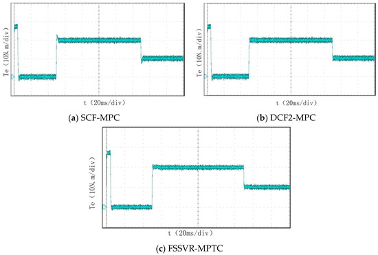
Figure 10.
Torque waveform during loading and unloading.
Table 3.
Comparison of three control strategies.
In summary, the experiments prove that the FSSVR-MPTC strategy not only has excellent dynamic performance but also has better steady-state performance of pulsation suppression under various operating conditions.
6. Conclusions
To address the computational complexity of voltage vector prediction and unreliable weight coefficient selection in dual three-phase PMSM (DT-PMSM) model predictive torque control (MPTC), this paper proposes a fast-switching table-based predictive method with online support vector regression (SVR)-optimized weight coefficients. The key conclusions include:
- The proposed MPTC strategy integrates sector division and fast-switching table prediction, eliminating complex voltage vector calculations while reducing computational load by 38% compared to conventional approaches;
- An offline-trained SVR model enables real-time optimal weight coefficient selection, achieving torque ripple reduction and current THD suppression versus traditional MPTC, with enhanced steady-state precision and transient dynamics;
- Future work will investigate the winding parameter variation impacts on the method’s robustness.
Author Contributions
In this study, H.Z. was responsible for writing the manuscript and providing technical guidance and was the core contributor to manuscript writing. S.F. provided innovative ideas and professional guidance for this study. G.W. edited the manuscript, provided references, made linguistic corrections, and polished the paper. All authors have read and agreed to the published version of the manuscript.
Funding
This work was supported by Changsha University of Science and Technology’s College Student Innovation and Entrepreneurship Training Program 0008001.
Data Availability Statement
The data obtained in this study can be obtained from the corresponding author upon request. Given the limitations of patent protection, this dataset is not convenient for public sharing.
Acknowledgments
The authors acknowledge the reviewers for providing valuable comments and helpful suggestions to improve the manuscript.
Conflicts of Interest
The authors declare that they have no competing interests.
Abbreviations
DT-PMSM—dual three-phase permanent magnet synchronous motor; MPTC—model predictive torque control; SV—support vector machine regression.
References
- Yan, L.; Zhu, Z.Q.; Qi, J.; Ren, Y.; Gan, C.; Brockway, S.; Hilton, C. Suppression of major current harmonics for dual three-phase PMSMs by virtual multi three-phase systems. IEEE Trans. Ind. Electron. 2022, 69, 5478–5490. [Google Scholar] [CrossRef]
- Polater, N.; Kamel, T.; Tricoli, P. Control and Power Sharing Strategy of Dual Three-Phase Permanent Magnet Synchronous Motor for Light Railway Applications. In Proceedings of the 2021 IEEE Vehicle Power and Propulsion Conference (VPPC), Gijon, Spain, 25–28 October 2021; pp. 1–6. [Google Scholar]
- Keller, D.; Kuenzler, M.; Karayel, A.; Werner, Q.; Parspour, N. Potential of dual three-phase PMSM in high performance automotive powertrains. In Proceedings of the 2020 International Conference on Electrical Machines (ICEM), Gothenburg, Sweden, 23–26 August 2020; pp. 1800–1806. [Google Scholar]
- Kolano, K. New Method of Vector Control in PMSM Motors. IEEE Access 2023, 11, 43882–43890. [Google Scholar] [CrossRef]
- Nasr, A.; Gu, C.; Wang, X.; Buticchi, G.; Bozhko, S.; Gerada, C. Torque-Performance Improvement for Direct Torque-Controlled PMSM Drives Based on Duty-Ratio Regulation. IEEE Trans. Power Electron. 2022, 37, 749–760. [Google Scholar] [CrossRef]
- Peng, J.; Yao, M. Overview of Predictive Control Technology for Permanent Magnet Synchronous Motor Systems. Appl. Sci. 2023, 13, 6255. [Google Scholar] [CrossRef]
- Lin, X.; Wu, C.; Yao, W.; Liu, Z.; Shen, X.; Xu, R.; Sun, G.; Liu, J. Observer-Based Fixed-Time Control for Permanent-Magnet Synchronous Motors with Parameter Uncertainties. IEEE Trans. Power Electron. 2023, 38, 4335–4344. [Google Scholar] [CrossRef]
- Lin, X.; Xu, R.; Yao, W.; Gao, Y.; Sun, G.; Liu, J.; Peretti, L.; Wu, L. Observer-Based Prescribed Performance Speed Control for PMSMs: A Data-Driven RBF Neural Network Approach. IEEE Trans. Ind. Inform. 2024, 20, 7502–7512. [Google Scholar] [CrossRef]
- Xu, R.; Shen, X.; Lin, X.; Liu, Z.; Xu, D.; Liu, J. Robust Model Predictive Control of Position Sensorless Driven IPMSM Based on Cascaded EKF-LESO. IEEE Trans. Transp. Electrif. 2025, 3, 1. [Google Scholar] [CrossRef]
- Zhang, Z.; Liu, Y.; Chen, J.; Guo, H.; Li, G. Predictive control strategy of permanent magnet synchronous motor amplitude control set model. Trans. China Electrotech. Soc. 2023, 15, 1530–1540. [Google Scholar]
- Geng, Q.; Qin, Z.; Jin, X.; Zhang, G.; Zhou, Z. Direct Torque Control of Dual Three-Phase Permanent Magnet Synchronous Motors Based on Master–Slave Virtual Vectors. World Electr. Veh. J. 2024, 15, 199. [Google Scholar] [CrossRef]
- Kawai, H.; Zhang, Z.; Kennel, R. Finite Control Set Model-Predictive Speed Control with a Load Torque Compensation. IEEJ Trans. Electr. Electron. Eng. 2018, 33, 2935–2945. [Google Scholar] [CrossRef]
- Dharmendra Kumar, P.; Ramesh, T. Investigation of Torque Ripple Behaviour for Five-Level Inverter-Fed Modified Model Predictive Torque Control-Based PMSM Drive. IETE Tech. Rev. 2022, 40, 252–267. [Google Scholar] [CrossRef]
- Chen, Y.; Tang, Z.; Chen, Z.-Y. Twelve-Sector Direct Torque Control without Flux Closed-Loop for PMSM. Electr. Power Compon. Syst. 2022, 50, 1237–1249. [Google Scholar]
- Xu, Y.; Shi, T.; Yan, Y.; Gu, X. Dual-Vector Predictive Torque Control of Permanent Magnet Synchronous Motors Based on a Candidate Vector Table. Energies 2019, 12, 163. [Google Scholar] [CrossRef]
- Zhang, C.; Xiong, Z.; Zhang, Y.; Xie, H.; Zhang, P. Fast Predictive Switching Table-Based Model Predictive Torque Control for PMSM. Prog. Electromagn. Res. C 2022, 123, 135–150. [Google Scholar] [CrossRef]
- Tu, W.; Luo, G.; Liu, W. Prediction of current control by finite control set model of permanent magnet synchronous motor based on fuzzy dynamic cost function. Trans. China Electrotech. Soc. 2017, 32, 89–97. [Google Scholar]
- Zhang, Z.; Sun, Q.; Di, Q.; Wu, Y. A Predictive Torque Control Method for Dual Three-Phase Permanent Magnet Synchronous Motor Without Weighting Factor. IEEE Access 2021, 9, 112585–112595. [Google Scholar] [CrossRef]
- Zhang, X.; Hou, B. Double Vectors Model Predictive Torque Control Without Weighting Factor Based on Voltage Tracking Error. IEEE Trans. Power Electron. 2018, 33, 2368–2380. [Google Scholar] [CrossRef]
- Chen, L.; Xu, H.; Sun, X.; Cai, Y. Three-Vector-Based Model Predictive Torque Control for a Permanent Magnet Synchronous Motor of EVs. IEEE Trans. Transp. Electrif. 2021, 7, 1454–1465. [Google Scholar] [CrossRef]
- Zeng, Y.; Jiang, S.; Konstantinou, G.; Pou, J.; Zou, G.; Zhang, X. Multi-Objective Controller Design for Grid-Following Converters with Easy Transfer Reinforcement Learning. IEEE Trans. Power Electron. 2025, 40, 6566–6577. [Google Scholar] [CrossRef]
- Zeng, Y.; Xiao, Z.; Liu, Q.; Liang, G.; Rodriguez, E.; Zou, G.; Zhang, X.; Pou, J. Physics-Informed Deep Transfer Reinforcement Learning Method for the Input-Series Output-Parallel Dual Active Bridge-Based Auxiliary Power Modules in Electrical Aircraft. IEEE Trans. Transp. Electrif. 2025, 11, 6629–6639. [Google Scholar] [CrossRef]
- Tian, Y.; Zhang, Y.; Xiao, X.; Yildirim, T. Weighting factors design in model predictive direct torque control based on cascaded neural network. Asian J. Control. 2024, 26, 1323–1338. [Google Scholar] [CrossRef]
- Wu, D.; Wang, S. Comparison of road traffic accident prediction effects based on SVR and BP neural network. In Proceedings of the 2020 IEEE International Conference on Information Technology, Big Data and Artificial Intelligence (ICIBA), Chongqing, China, 6–8 November 2020; Volume 1, pp. 1150–1154. [Google Scholar]
- Liu, S.; Liu, C. Direct Harmonic Current Control Scheme for Dual Three-Phase PMSM Drive System. IEEE Trans. Power Electron. 2021, 36, 11647–11657. [Google Scholar] [CrossRef]


Disclaimer/Publisher’s Note: The statements, opinions and data contained in all publications are solely those of the individual author(s) and contributor(s) and not of MDPI and/or the editor(s). MDPI and/or the editor(s) disclaim responsibility for any injury to people or property resulting from any ideas, methods, instructions or products referred to in the content. |
© 2025 by the authors. Licensee MDPI, Basel, Switzerland. This article is an open access article distributed under the terms and conditions of the Creative Commons Attribution (CC BY) license (https://creativecommons.org/licenses/by/4.0/).