Article

Genetic Algorithm-Based Design Optimization of Electromagnetic Valve Actuators in Combustion Engines

1
School of Aerospace and Mechanical Engineering, Korea Aerospace University, Goyangsi, Gyeonggido 412-791, Korea
2
Department of Mechanical Engineering, Yeungnam University, Gyeongsan, Gyeongbuk 712-749, Korea
3
Quinsta Technology, Torrance, CA 90505, USA
*
Author to whom correspondence should be addressed.
Energies 2015, 8(11), 13222-13230; https://doi.org/10.3390/en81112352
Submission received: 17 August 2015 / Revised: 2 November 2015 / Accepted: 3 November 2015 / Published: 20 November 2015

Abstract

:
In this research, the design of a new electromagnetic engine valve in the limited space of combustion engine is optimized by multidisciplinary simulation using MATLAB and Maxwell. An electromagnetic engine valve actuator using a permanent magnet is a new actuator concept for overcoming the inherent drawbacks of the conventional solenoid-driven electromagnetic engine valve actuator, such as high power consumption and so on. This study aims to maximize the vibration frequency of the armature to reduce the transition time of the engine valve. The higher performance of the new actuator is demonstrated by dynamic finite element analysis.

1. Introduction

Variable valve timing is a key technology in automobile combustion engines. It improves fuel efficiency by up to 15%, enhances torque output by up to 10% and reduces CO2 emission by up to 15% under different engine operating conditions [1,2]. The solenoid-driven electromagnetic engine valve actuator is the most advanced system among the devices that had been developed in the past several years to replace the traditional mechanically driven camshaft engine valve system [3,4].
In order to implement and design this system within the limited space of a combustion engine, there are numerous studies on solenoid-driven electromagnetic engine valves such as sensorless control, landing control and optimal design for the improvement of their performance. Mercorelli suggests a two-stage sliding-mode observer using Kalman filters to implement the sensorless control system of the electromagnetic engine valve [5,6,7]. Chlandy and Koch designed a closed-loop controller near the valve stroke bounds for the soft landing using a model which identifies combustion gas force variation [8]. Although they offered the highest flexibility in valve timing control, the solenoid-driven electromagnetic engine valve actuator suffers from an inherent problem of high-energy consumption for the operation of this system [4].
In order to solve the drawbacks associated with the solenoid-driven actuator from the viewpoint of optimal design, Kim and Lieu introduced a new electromagnetic engine valve actuator design that uses a permanent magnet [9]. This new actuator with a permanent magnet has much lower operating power consumption than the solenoid-driven actuator because of two main advantages: First, the residual induction of the permanent magnet can hold the valve in the closed position in the initial stage of ignition, and second, the actuator does not need power between valve events and feeds current only into the system at each valve transition period. Cho et al., proposed an inter-locking mechanism to solve unintended operations driven by external force such a shock while in open state of the electromagnetic engine valve actuator with permanent magnet [10]. However, the electromagnetic engine valve actuators in those studies adapt moving permanent magnets in the armature. This type has potential problems in terms of the reliability of the permanent magnet and the reduction of the dynamic performance.
In this research, an optimal design of the electromagnetic engine valve with fixed permanent magnetic is suggested. Also, the genetic algorithm is adapted for the optimization process to reduce the transient time of strokes for higher engine speed.
Figure 1 shows a schematic diagram of the newly suggested actuator. It is composed of permanent magnets, electromagnetic coil (solenoid), a laminated steel core and armature, two springs and a valve body. The armature and the valve compose one continuous body. Accordingly, the engine valve closes and opens as the armature moves up and down. The total travel distance of the armature is 8 mm.
Figure 1. Schematic diagram of new electromagnetic engine valve actuator suggested by Kim and Lieu.
Energies 08 12352 g001
Figure 2 shows the operating principle. The blue solid arrows show the magnetic flux generated by the permanent magnets and the red dotted arrows show the flux generated by the electromagnetic coil. As shown in Figure 2a, the permanent magnets latch the armature in the upper position, i.e., the valve is closed because the magnetic force exceeds the spring force. In order to open the engine valve, the coil is energized. When the flux of permanent magnets becomes partially cancelled as shown in Figure 2b, the spring force exceeds the magnetic force and the armature is released and accelerated by the stored energy in the springs, and the engine valve starts to open. After the armature passes the neutral position of the stroke, the electromagnetic coil is reversely energized. Then, the permanent magnets and the electromagnetic coil catch the armature at the lower end position as shown in Figure 2c. The motion from the lower end to the upper end follows the steps above in reverse order.
Transition time is defined as the duration in which the valve moves from the closed position to the open position or from the open position to the closed position. As the transition time becomes smaller, the engine valve actuator can yield higher maximum engine speeds. The transition time of the existing design is 3.9 milliseconds, which yields about 5000 rpm of maximal engine speed. The transition time of the valve can be shortened by increasing the mechanical vibration frequency of armature which is connected to the valve.
The mechanical vibration frequency of armature is defined by k / m . Here, m is the total moving mass of the armature and engine valve those are one rigid body and oscillating together. k is the equivalent spring stiffness. The maximum available stiffness of the spring is proportional to the magnitude of the magnetic latching force. The magnetic latching force by the permanent magnet at the lower and upper ends of the stroke is designed to be 100 N larger than the spring force because of gas disturbance for safe latching. In this paper, the actuator design is optimized for the reduction of the stroke transition time, which is achieved by maximizing the vibration frequency of armature. The optimization is carried out by multidisciplinary simulations of Maxwell and MATLAB based on finite element analysis (FEA) and genetic algorithm (GA). In addition, 2-D dynamic finite element analyses are performed to demonstrate the enhanced performance by the optimization.
Figure 2. Principle of operation (a) at the upper end (b) at starting end (c) at the lower end.
Energies 08 12352 g002

2. Design Optimization

2.1. Optimization Variables and Constraint Conditions

Figure 3 shows the design variables of the optimization. Also, several boundary conditions required to obtain a realistic design are considered as follows:
  • The thickness and width of the actuator are fixed. The height of the actuator, however, can be extended because extra space in the direction of height is created due to the removal of the camshaft.
  • Maximum teeth width (Wt) is set such that the minimum gap between teeth is 10 mm.
  • The size of the permanent magnet remains fixed and the same as the one of the existing design. The optimization in this study does not aim to enlarge the magnetic latching force by increasing of the size of the permanent magnets.
  • After the dimensions of the core and teeth are determined, the width (Wa) and height (Ha) of the armature are restricted so that the armature can properly fit inside the air band, which allows 8 mm longitudinal air-gap for the required armature motion.
  • The shapes of the lower teeth and the upper teeth are designed to be symmetric to the neutral line.
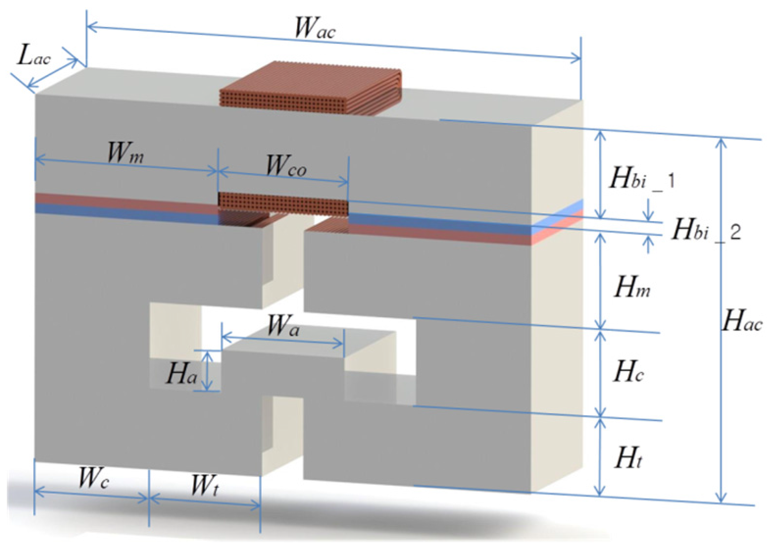
Figure 3. Design optimization variables for maximizing frequency of vibration at bottom end position of armature.
Energies 08 12352 g003

2.2. Objective Function

The objective function of optimization maximizes the frequency of actuator vibration, as expressed by Equation (1). In this equation, we consider 100 N as a disturbance force based on an automobile company’s experimental data:
ω n = k m = ( F L a t c h i n g 100 ) / x max v a × ρ s + m v
where:
  • k: Available spring stiffness;
  • m: Moving mass including armature and engine valve;
  • ω n : Frequency of vibration (natural frequency);
  • F L a t c h i n g : Magnetic latching force;
  • x max : Distance from neutral to lower end of stroke;
  • v a : Volume of armature;
  • ρ s t e e l : Mass density of steel;
  • m v : Mass of engine valve.

2.3. Optimization Procedures and Results

2.3.1. Optimization Procedure and Methods

When optimizing the proposed structure, the trial-and-error method based on physics, or the conjugate-gradient and quasi-Newton method can be used. However, it is difficult for all the above methods to lead to an optimal solution, especially for multi-parameter optimization problems. Unlike these local optimization techniques above, genetic algorithms (GAs) are not highly dependent on either initial conditions or constraints in the solution domain [11]. Therefore, we employ the GA, a global search technique in this paper.
Figure 4 shows the GA process for the optimal design. First, a population of actuators is randomly generated. Each individual in the population is a series of binary string (chromosome) that represents one complete actuator, as shown in Figure 5. Then, each gene in the chromosome is decoded to actual parameters using a binary-decoding method given by Equation (2):
P = P min + ( P max P min 2 N 1 ) n = 0 N 1 2 n b n
where P is the actual parameter based on the given minimum and maximum values of P and bn is the binary bit (0 or 1) in the n-th place of the gene corresponding to parameter P. The decoded parameters are passed to the Maxwell for evaluation. The goodness of each chromosome is determined by Maxwell. In the simulation platform, the program written by MATLAB writes a VBScript to execute Maxwell for the electromagnetic 3-D static finite analysis and reads the value of the latching force to determine the frequency of armature vibration. Once the simulation for a given population finishes, GA acts on the chromosomes to generate a new population through crossover and mutation operations.
Since the goal of this structure is to maximize the natural frequency, the Fitness Function can be simply written as Equation (3):
Fitness Function = Maximize ( ω n )
Figure 4. Genetic algorithm process for evolution toward a global solution.
Energies 08 12352 g004
Figure 5. Chromosome structure.
Energies 08 12352 g005
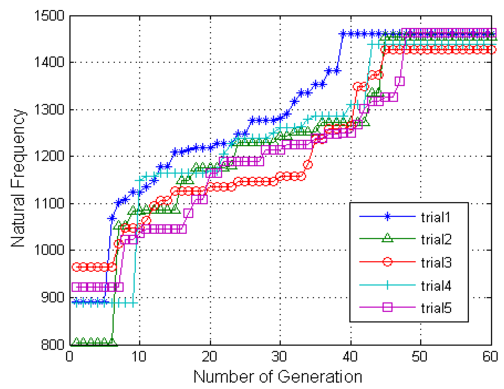
Several independent runs are performed by varying the population sizes and the ratio of crossover to mutation to assure convergence to the optimal design. Figure 6 shows a good convergence to some optimal values.
Figure 6. Best fitness values in each generation.
Energies 08 12352 g006

2.3.2. Optimization Results

Table 1 shows the optimized dimensions of the actuator. When the size of the armature was decreased, the moving mass was reduced, but the widths of the teeth and core were increased.
Table 1. Actuator Dimensions (all dimensions in mm).
SymbolQuantityExiting DimensionsNew Optimized Dimensions
LacThickness of actuator38.138.1
WacWidth of actuator120.65120.65
HacHeight of actuator93.3495
WcoWidth of coil31.7531.75
WmWidth of magnet44.4544.45
HmHeight of magnet4.76254.7625
WaWidth of armature44.4530.216
HaHeight of armature19.0312
WtWidth of teeth34.2927.325
HtHeight of teeth19.0519
WcWidth of core19.0528
Hbi_1Height of back iron 119.0528.75
Hbi_2Height of back iron 24.76253.5
Table 2 compares the static characteristics between the existing design and the optimal design. The magnetic latching force at the end position of the stroke falls from 1525 to 1262 N. Therefore the obtainable maximal stiffness of spring is reduced from 358 to 292 kN/m, and the moving mass including armature and engine valve is reduced from 284 to 136 gram. As a result, the natural frequency is improved by 30%.
Table 2. Comparison of existing design and optimal design.
CharacteristicsExisting DesignOptimal Design
Magnetic latching force (N)15251262
Available Spring stiffness (kN/m)358292
Moving mass (kg)0.2840.136
Natural frequency11231465

3. Dynamic Simulation

Transient 2-D finite-element analyses (FEA) of the existing design and the optimal design in Table 3 were carried out to compare their dynamic performances and to demonstrate the enhanced dynamic performance of the system by optimization. The actuator systems are composed of three subsystems: a mechanical system, an electrical system and a magnetic system, which are all coupled to each other. Governing equations, initial conditions and boundary conditions of each subsystem are given as follows.: The magnetic property of SmCo28 is assigned to the permanent magnets and the nonlinear magnetization curve of 1010 steel is used for the magnetic properties of the stator and armature. Table 3 shows the physical properties of the engine valve system. The dynamic motions of the armature from the lower end to the upper end of the stroke are simulated for the time-step of 20 μs over a period of 4 ms using both 2-D FE models of the existing design and the optimal design:
× ( 1 μ × A z ) = J e x t + 1 μ × M
Boundary condition: A z = 0
where:
  • A z : Magnetic vector potential in the out of plane direction;
  • μ : Permeability of the material including armature and engine valve;
  • M : Magnetization of the permanent magnet;
  • J e x t : Current density.
d λ ( i , x ) d t + R i = V
Initial condition i ( 0 ) = 0
where:
  • λ: Flux linkage;
  • i: Current;
  • R: Resistance.
m x ¨ + c x ˙ + k e q x = F m a g n e t i c + F g r a v i t y
Initial condition x ( 0 ) = 4   mm and x ˙ ( 0 ) = 0
where:
  • c : Damping coefficient;
  • F m a g n e t i c : Magnetic force;
  • F g r a v i t y : Gravity force.
Table 3. Physical properties of the valve system.
ParameterValue
Residual Induction (T)1.0188
Coercivity (A/m)−754,176
Input voltage (V)200
Number of turns (turns)200
Resistance (Ω)1
Figure 7 shows the position profiles of the armature in the existing design and the optimal design. The slope of the position profile versus time of the optimal design is steeper than that of the existing design due to the higher vibration frequency. The armatures of the existing and optimal designs are released from the lower end of the stroke at 0.5 ms and at 0.7 ms, respectively. These delays are due to the inductance of coil; in other words, there is a delay time for the coil current to reach a sufficient level to make the magnetic force lessthan the spring force. At 2.4 ms, the moving armature of the optimal design passes the neutral position of the stroke where the magnetic force and the spring force are zero at the maximum traveling speed, whereas that of the existing design passes by the neutral position at 2.6 ms. At 3.56 ms, the armature of the optimal design arrives at the upper end of the stroke whereas that of the existing design arrives at 3.9 ms. Table 4 shows the dynamic performance comparison between the existing design and the optimal design. As a result of the optimization, the transition time was shortened by 8.7% from 3.9 to 3.56 ms, and the maximum speed during transition was improved by 26.7% from 3.631 to 4602 m/s.
Figure 7. Position profiles versus time of existing design and optimal design.
Energies 08 12352 g007
Table 4. Dynamic performance of existing design and optimal design.
ItemExisting DesignOptimal Design
Transition time (ms)3.93.56
Maximum speed (m/s)3.6314602

4. Conclusions

This paper presents the optimization of a newly designed electromagnetic engine valve actuator. The optimization based on a genetic algorithm and 3-D FEA using multidisciplinary simulations of MATLAB and Maxwell, improved the vibration frequency by 30%. In addition, the enhanced performance of the optimized actuator was demonstrated by 2-D dynamic finite element analysis. The result showed the reduction of the stroke transition time by 8.7%, which enabled the new engine valve actuator to achieve higher maximum engine speed than the existing actuator. Additionally, suggested optimization because the genetic algorithm and FEA-based optimization method has potential advantages.

Author Contributions

Seung Hwan Lee wrote the paper mainly and revised the manuscript. Hwa Cho Yi designed the mechanism system and Kyuyoung Han performed the optimization. Jinho Kim proposed the novel design of actuator and managed to write the paper.

Conflicts of Interest

The authors declare no conflict of interest.

References

  1. Barkan, P.; Dresner, T. A Review of Variable Valve Timing Benefits and Modes of Operation; SAE Technical Paper Series, Paper 891676; SAE International: Warrendale, PA, USA, 1989. [Google Scholar]
  2. Pischinger, M.; Salber, W.; van der Staay, F.; Baumgarten, H.; Kemper, H. Benefits of the Electromechanical Valve Train in Vehicle Operation; SAE Technical Paper Series, Paper 2000-01-1223; SAE International: Warrendale, PA, USA, 2000. [Google Scholar]
  3. Sugimoto, G.; Sakai, H.; Umemoto, A.; Shimizu, Y.; Ozawa, H. Study on Variable Valve Timing System Using Electromagnetic Mechanism; SAE Technical Paper Series, Paper 2004-01-1869; SAE International: Warrendale, PA, USA, 2004. [Google Scholar]
  4. Giglio, V.; Iorio, B.; Police, G. Analysis of Advantages and of Problems of Electromagnetic Valve Actuators; SAE Technical Paper Series, Paper 2002-01-1105; SAE International: Warrendale, PA, USA, 2002. [Google Scholar]
  5. Mercorelli, P. A two-stage sliding-mode high-gain observer to reduce uncertainties and disturbances effects for sensorless control in automotive applications. IEEE Trans. Ind. Electron. 2015, 62, 5929–5940. [Google Scholar] [CrossRef]
  6. Mercorelli, P. A hysteresis hybrid extended Kalman Filter as an observer for sensorless valve control in camless internal combustion engines. IEEE Trans. Ind. Electron. 2012, 48, 1940–1949. [Google Scholar] [CrossRef]
  7. Mercorelli, P. A two-stage augmented extended Kalman filter as an observer for sensorless valve control in camless internal combustion engines. IEEE Trans. Ind. Electron. 2012, 59, 4236–4247. [Google Scholar] [CrossRef]
  8. Chladny, R.R.; Koch, C.R. Flatness-based tracking of an electromechanical VVT actuator with disturbance observer feed-forward compensation. IEEE Trans. Control Syst. Technol. 2008, 16, 652–663. [Google Scholar] [CrossRef]
  9. Kim, J.; Chang, J. A new electromagnetic linear actuator for quick latching. IEEE Trans. Magn. 2007, 43, 1849–1852. [Google Scholar] [CrossRef]
  10. Cho, D.; Woo, D.; Ro, J.; Chung, T.; Jung, H. Novel electromagnetic actuator using a permanent magnet and an inter-locking mechanism for a magnetic switch. IEEE Trans. Magn. 2013, 49, 2229–2232. [Google Scholar] [CrossRef]
  11. Johnson, J.M.; Rahmat-Samii, Y. Genetic algorithms in engineering electromagnetics. IEEE Antennas Propag. Mag. 1997, 39, 7–21. [Google Scholar] [CrossRef]