Article

Research on Shaft Subsynchronous Oscillation Characteristics of Parallel Generators and SSDC Application in Mitigating SSO of Multi-Generators

College of Electrical Engineering, Zhejiang University, Hangzhou 310027, China
*
Author to whom correspondence should be addressed.
Energies 2015, 8(3), 1644-1662; https://doi.org/10.3390/en8031644
Submission received: 10 November 2014 / Revised: 4 January 2015 / Accepted: 9 February 2015 / Published: 27 February 2015
(This article belongs to the Collection Smart Grid)

Abstract

:
Subsynchronous oscillation (SSO) of generators caused by high voltage direct current (HVDC) systems can be solved by applying supplemental subsynchronous damping controller (SSDC). SSDC application in mitigating SSO of single-generator systems has been studied intensively. This paper focuses on SSDC application in mitigating SSO of multi-generator systems. The phase relationship of the speed signals of the generators under their common mechanical natural frequencies is a key consideration in SSDC design. The paper studies in detail the phase relationship of the speed signals of two generators in parallel under their shared mechanical natural frequency, revealing regardless of whether the two generators are identical or not, there always exists a common-mode and an anti-mode under their common natural frequency, and the phase relationship of the speed signals of the generators depends on the extent to which the anti-mode is stimulated. The paper further demonstrates that to guarantee the effectiveness of SSDC, the anti-phase mode component of its input signal should be eliminated. Based on the above analysis, the paper introduces the design process of SSDC for multi-generator systems and verifies its effectiveness through simulation in Power Systems Computer Aided Design/Electromagnetic Transients including Direct Current (PSCAD/EMTDC).

1. Introduction

Apart from series-compensated AC transmission lines, power electronics converters like those in High-Voltage Direct Current (HVDC) systems can also cause Subsynchronous Oscillation (SSO) of generators nearby [1,2,3,4]. This category of SSO usually results from the fast-response characteristics of the controller of the converters, due to which the electrical system provides negative electrical damping in the subsynchronous frequency range [3,4]. The electrical damping also depends on HVDC power level, AC system strength and parameters of the converter controllers [4]. SSO due to HVDC was first experienced in the Square Butte system in America [1]. In China, several HVDC systems have experienced similar problems in recent years [5,6]. As the number of HVDC systems in China grows, it is highly possible that the SSO problem will become more severe.
SSO problems due to HVDC can generally be solved applying supplemental subsynchronous damping controller (SSDC) [2,6,7,8,9]. One kind of SSDC [6,8,9] takes signals reflecting SSO information as its input signal, and its output signal is a current or power reference deviation, added to the constant current or power reference value of the converter controller, thus inducing an additional electrical torque on the generators suffering SSO. This torque, T ˜ e ( λ ) , can be regulated by properly selecting the structure and parameters of the SSDC, so that it is within ± 90 ° with respect to the speed deviation, ω ˜ , of the generator in the whole subsynchronous frequency range, providing an additional positive damping to mitigate SSO. SSDC based on such a principle has clear physical meaning and high reliability, and is widely used.
SSDC application in mitigating SSO in single-generator systems has been intensively studied and its effectiveness is well verified. As for multi-generator systems, relevant research is comparatively lacking. In fact, SSDC design for multi-generator systems is more complex than for single-generator systems, especially when the multiple generators share several mechanical natural frequencies. If there are multiple identical generators in parallel, they share all their natural frequencies. In reference [10], Alden studies shaft dynamics of closely coupled identical generators, and reveals that when two identical generators operate in parallel, under each of their shared mechanical natural frequencies, the oscillation modes of the two generators are no longer de-coupled. Instead, there arises two modes in which both generators participate, namely, a common-mode in which the masses of both generator shafts oscillate in-phase and an anti-mode in which the masses of both generator shafts oscillate out-of-phase. As the anti-mode can hardly be excited, the identical generators, whose common-mode reveals their common behavior, can be represented by a single equivalent generator. For non-identical generators, equivalence is barely possible. Reference [11] investigates the torsional interaction of two non-identical generators with a common mechanical natural frequency, revealing that there will be noticeable phase difference of speed deviations of the two non-identical generators under their common mechanical natural frequency when oscillation occurs. This paper further investigates such situation, showing that if the equivalent electrical stiffness coefficients of the system are much smaller than the modal stiffness coefficients of the generator shafts, then in the anti-mode, the generator masses of the two shafts will oscillate almost out-of-phase, and the oscillation amplitudes of the generators masses are nearly reversely in proportion to the corresponding modal inertias. The reason why there is phase difference between speed deviations of the two generators when oscillation occurs is that both the common-mode and the anti-mode will be excited and the relative extent to which the two modes are excited is uncertain. This paper also shows that due to the uncertain phase difference between the generator speed deviations, taking the speed signal of either generator as the input of the SSDC will hardly guarantee its effectiveness in mitigating oscillation of both generators. Furthermore, this paper points out that as the anti-mode is mainly due to the local interaction of the two generators and does not couple with the HVDC system, it is inherently stable. By appropriate linear combination of the speed signals of the generators, the anti-mode component can be eliminated and only the common-mode component will be left. If this combined signal is taken as the input signal of SSDC, as the common-mode signal of the generators are in-phase and they have a definite phase relationship, the design of the SSDC becomes feasible and the effectiveness of the SSDC can be guaranteed.
Apart from the above considerations, for good SSDC design, it is important that in various system operating conditions, for instance, generators put into or out of service, power level altered, or network configuration changed, the SSDC should always be effective.
The effectiveness of the SSDC, designed for a system containing four generators in two types, in various system operating conditions is verified by time-domain simulation.
The paper is organized as follows. Section 2 reviews the design method of SSDC based on phase-compensation principle. Section 3 analyzes in detail the relevant issues about SSDC design for multi-generator system, including phase relationship of key variables, shaft SSO characteristics of parallel generators, and separation of common-mode and anti-mode in SSDC input signal. In Section 4, a case study of a system containing four generators in two types is carried out. The effectiveness of the SSDC designed for this system in various system operating conditions is verified by time-domain simulation. Conclusions are presented in Section 5.

2. SSDC Design Method Based on Phase-Compensation Principle

In reference [9], Tang introduces the SSDC design method based on phase compensation method; now we briefly review it as follows.
Referring to Figure 1a, the input signal of SSDC is the generator speed deviation, ∆ω , and the output signal of SSDC is a reference direct current deviation signal, I d _ ref , which is then transmitted to the constant-direct-current controller of the HVDC converter (shown in Figure 2). The output signal of SSDC, I d _ ref , will then induce an additional electrical torque, T e , on the generator. For each subsynchronous oscillation mode frequency λ f 0 ( 0 < λ < 1 , f 0 is the rated frequency of the power grid) of the system, the aim of SSDC design is that the additional electrical torque induced on the generator due to SSDC, Δ T ˜ e ( λ ) , and the speed deviation of the generator in oscillation, Δ ω ˜ ( λ ) , have a phase difference within ± 90 ° . Under this condition, the generator will experience a positive damping torque to mitigate the oscillation, as is shown in Figure 1b. This phase difference is composed of two parts. One part is the phase difference between the induced additional electrical torque, Δ T ˜ e ( λ ) , and the current reference value deviation of the converter, I ˜ d _ ref ( λ ) . This part is denoted as TRI ( λ ) . The other part is the phase difference between the current reference value deviation of the converter, I ˜ d _ ref ( λ ) , and the speed deviation, Δ ω ˜ ( λ ) . This part is actually the phase compensated by SSDC and it is denoted as SSDC ( λ ) .
Figure 1. Phase relationship of key variables in SSDC design: (a) transfer scheme; (b) phasor diagram.
Energies 08 01644 g001
Figure 2. Topology of SSDC with multi-modal structure based on the phase-compensation principle.
Energies 08 01644 g002
Hence, our basic aim is that 90 ° < S S D C ( λ ) + T R I ( λ ) < 90 ° for each subsynchronous oscillation mode frequency λ f 0 . In SSDC design, we can firstly obtain TRI ( λ ) by the test signal method [12] in time-domain simulation software such as PACAD, according to which SSDC ( λ ) can be determined then. SSDC ( λ ) , the desired phase-frequency characteristic of SSDC, can be realized through lead-lag components. In addition, as the frequency of each subsynchronous oscillation mode is mainly determined by the mechanical parameters of generators and thus almost fixed, the SSDC can adopt the multi-modal structure [6], as is shown in Figure 2. This multi-modal structure is also based on the phase-compensation principle. In this structure, a band-pass filter for each oscillation mode frequency is applied to the input signal of SSDC. Referring to Figure 2, we can see that control of each mode can thus be decoupled and generally one lead-lag stage for each mode is sufficient to compensate the corresponding T R I ( λ ) . Adopting multi-modal structure can achieve better flexibility and effectiveness. In addition, this structure is also insensitive to noises in signals with application of filters.
After the condition 90 ° < S S D C ( λ ) + T R I ( λ ) < 90 ° is satisfied, the proportional gain of each mode in SSDC should be properly set to guarantee that the SSDC can provide sufficient damping toque to the generators to effectively damp SSO.
Admittedly, as the power stations are usually located miles away from converter stations, if speeds of generators are taken as the input signals of SSDC, signal transmission may cause time delay or interference problems. Hence, from the practical standpoint, it is preferable to choose a signal native in the converter station as the input signal of SSDC. References [2,6] take frequency of the converter bus voltage as the input signal of SSDC. For multi-generator situations, however, it is difficult to choose a native signal which can reflect the oscillation conditions of all the generators. Considering that only generators near converter stations (for instance, within 300 km) may suffer SSO and signal transmission time delay of optical fibers corresponding to such distance is generally within 1 ms, which is very small compared to subsynchronous oscillation periods, we may believe that taking generator speed as the input signal of SSDC is feasible.

3. SSDC Design When There are Multiple Generators Near HVDC Converter

The principle of SSDC design for multiple generator system is similar to what is introduced in Section 2. However, the issue we should pay special attention is that, any output signal, I ˜ d _ ref ( λ ) , of SSDC will induce an additional electrical torque, T ˜ ek ( λ ) ( k = 1 ,   2 ,   ,   N , N is the total number of generators in the system.), on each generator in the system. That is to say, if we try to utilize only one SSDC to damp the SSO of the multiple generators simultaneously, it will not be easy to decouple the control of the generators and an interaction problem may arise, which we will explain by a system containing two generators in parallel as follows.
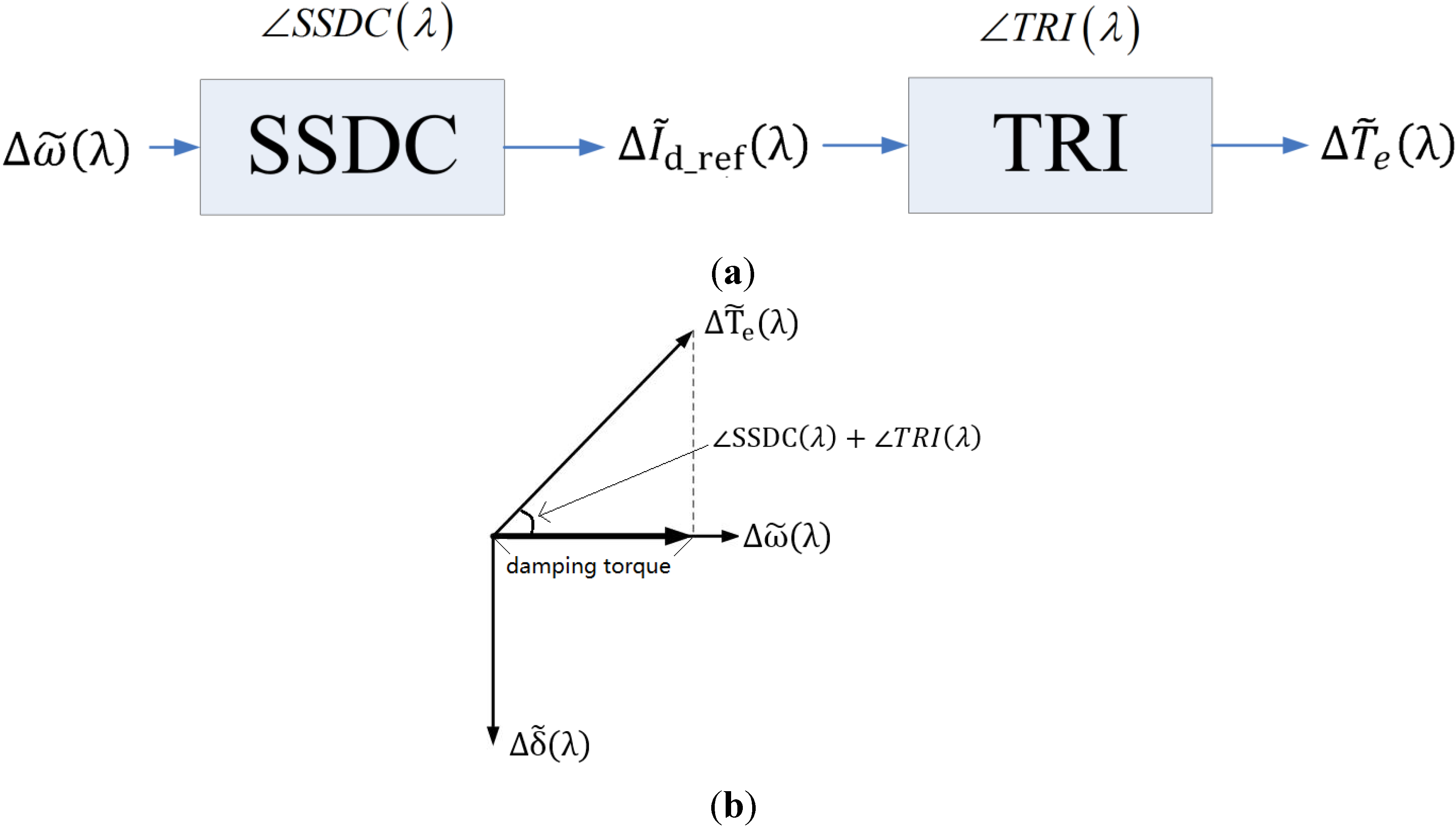
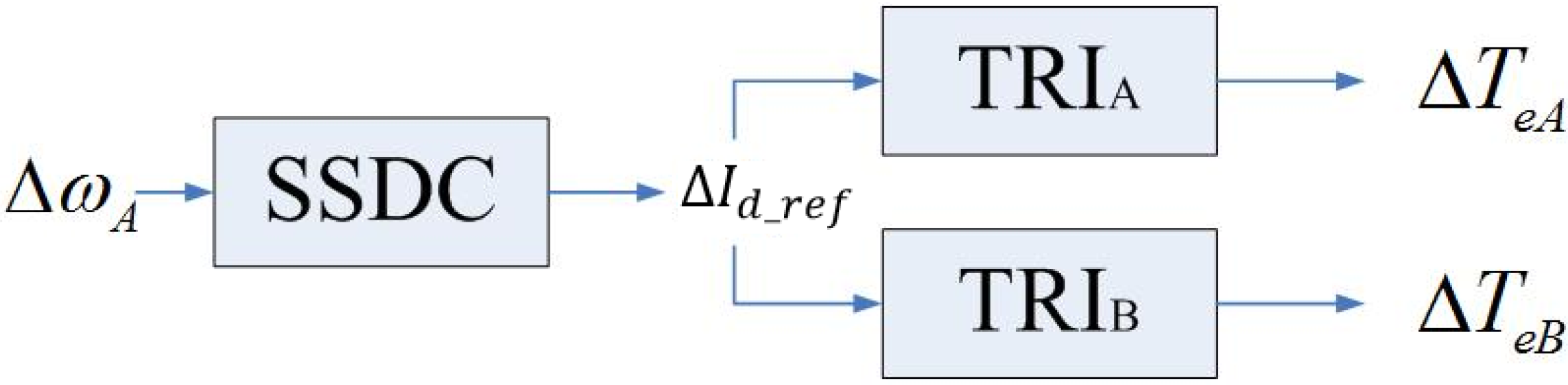
Assume that there are two generators operating in parallel in the system, which we denote as Generator A and Generator B. Suppose Generator A has a mechanical natural frequency λ A f 0 . When SSO occurs, the speed deviation of Generator A will contain the component, Δ ω ˜ A ( λ A ) , of this frequency. Correspondingly, the SSDC will output a current reference signal I ˜ d _ ref ( λ A ) . It should be noted that this current reference signal will not only induce an additional electrical torque, T ˜ eA ( λ A ) , of frequency λ A f 0 on Generator A. Simultaneously, it will induce an additional electrical torque, T ˜ eB ( λ A ) of the same frequency on Generator B. If Generator B has no mechanical natural frequency close to λ A f 0 (within 0.3 Hz, for instance), then we can believe that T ˜ eB ( λ A ) has no obvious effect on shaft oscillation of Generator B. On the other hand, if Generator B happens to have a natural frequency close to λ A f 0 , special attention should be paid to the interaction between the two generators.
Now assume that the two generators have the common mechanical natural frequency of λ A f 0 . For clarity, phase relationship of key variables in this situation is shown in Figure 3. In Figure 3, I ˜ d _ ref ( λ A ) is the output signal of SSDC. TRI A ( λ A ) and TRI B ( λ A ) are the phase differences between the additional electrical torques induced on the generators, T ˜ eA ( λ A ) and T ˜ eB ( λ A ) , and I ˜ d _ ref ( λ A )  respectively .  Δ ω ˜ A ( λ A ) and Δ ω ˜ B ( λ A ) are the speed deviations of the two generators under the common natural frequency. From Figure 3, it is clear that the phase difference of T ˜ eA ( λ A ) and T ˜ eB ( λ A ) is TRI A ( λ A ) TRI B ( λ A ) , which is almost constant and depends on the configuration of the electrical system. Then, the question arises that whether or not the phase difference of the speed deviations, Δ ω ˜ A ( λ A ) and Δ ω ˜ B ( λ A ) , is also constant. If it is not so, obviously the SSDC cannot be guaranteed to provide a positive damping for the two generators simultaneously. Hence the phase difference of the speed deviations of the two generators under their common mechanical natural frequency is the subject we are going to treat.
Figure 3. Phase relationship of key variables concerned in double-generator SSDC design.
Energies 08 01644 g003

3.1. Shaft Oscillation Characteristic of Double Generators Having a Common Mechanical Natural Frequency

For double identical generators operating in parallel, eigenvalue analysis results will show that under each common natural frequency of the generators, there are two oscillation modes in which both generators will participate, namely, a common-mode and an anti-mode. In common-mode, the masses in each generator shaft oscillate in-phase. Common-mode reflects the interaction between the outer electrical system and the two generators. On the other hand, in anti-mode, the masses in each generator shaft oscillate out-of-phase. Anti-mode reflects the native interaction between the two generators [10].
If our main attention is on the torsional characteristic of the shaft systems of the generators, we can briefly treat the electrical system as ‘electrical springs’ [10]. That is to say, we will approximately have T e = k ∆δ , from the classical power-angle equation that P e = E S E R sin δ / X e q , or T e P e = E S E R cos δ 0 ∆δ / X e q . Also, under a natural frequency ω m of a generator shaft, from the perspective of the outer system, the generator shaft can be viewed as a single equivalent mass in connection with a single equivalent ‘mechanical’ spring. The inertia, M , of the equivalent mass is called the modal inertia and we have M = J k ( v k / v g ) 2 where J k are the inertias of the real masses in the shaft and v k and v g are the mode shapes of the corresponding mode [13]. The stiffness coefficient of the equivalent ‘mechanical’ spring, s m , can be calculated from the relationship that s m / M = ω m , where ω m 
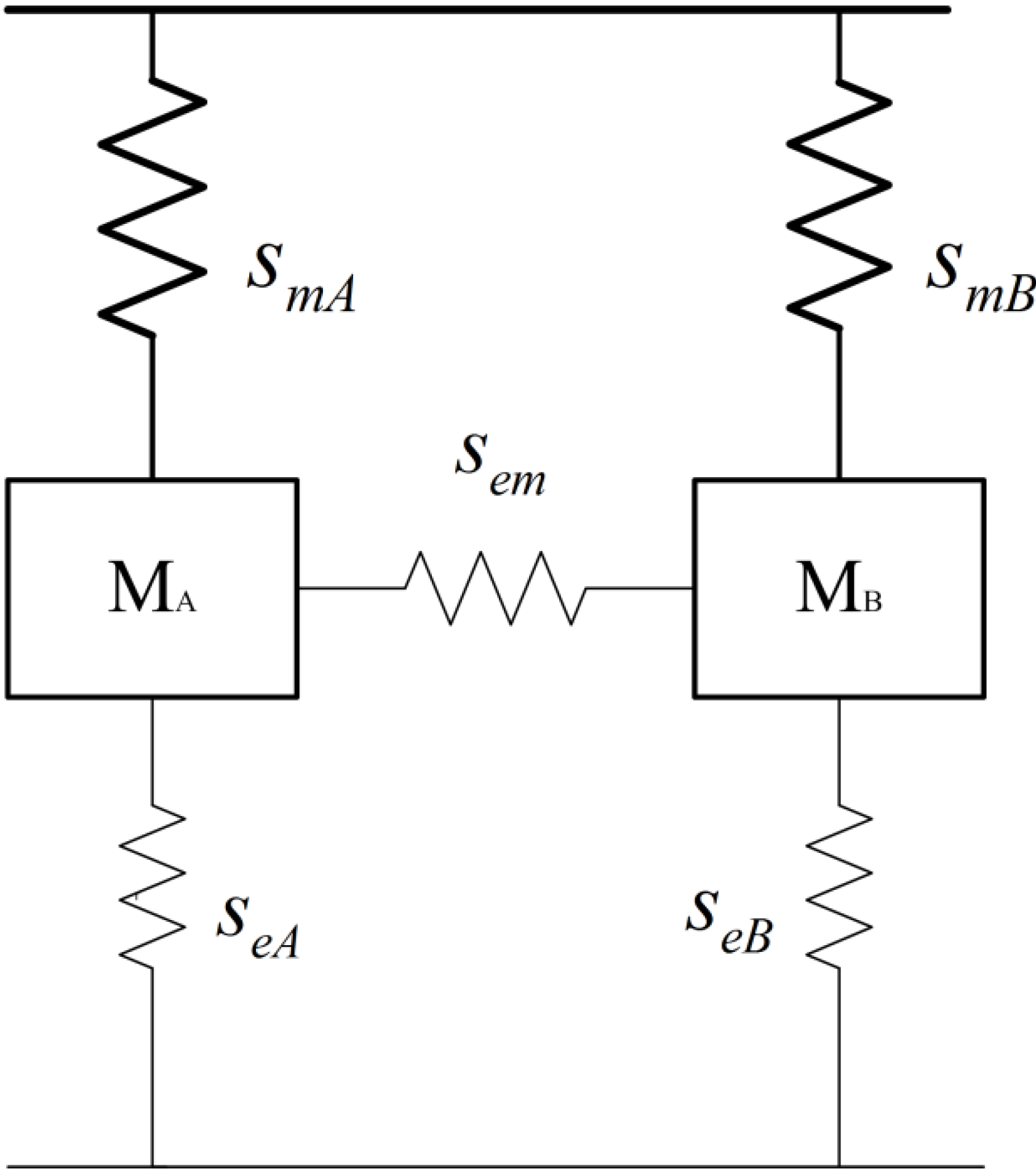
is the natural frequency. Combing the equivalent electrical system and the equivalent mechanical system, under the common mechanical natural frequency of the generators, the whole system can be represented by a simplified mechanical equivalent, shown in Figure 4. In Figure 4, M A and M B are respectively the modal inertias of generator A and generator B under their common natural frequency, and s mA and s mB are the corresponding equivalent modal mechanical stiffness coefficients. s eA , s eB and s em are the equivalent electrical stiffness coefficients, whose magnitudes are well separated with those of mechanical ones from observation of typical values, namely, s eA ,   s eB ,   s em s mA ,   s mB . Hence, “electrical springs” have little impact on the mechanical natural frequencies and the modal shapes of the generator shafts.
Figure 4. Mechanical equivalent of double-generator system.
Energies 08 01644 g004
Now, we analyze situations with two non-identical generators operating in parallel. Denoting the common natural frequency of the two generators as ω common , we have:
s mA / M A = s mB / M B = ω common
The state equation of the system is:
[ M A 0 0 M B ] [ δ ¨ A δ ¨ B ] = [ s mA s eA s em s em s em s mB s eB s em ] [ δ A δ B ]
where δ A and δ B are the power angle deviations of the two generators. Considering s eA , s eB s mA , s mB , Equation (2) can be simplified to:
[ M A 0 0 M B ] [ δ ¨ A δ ¨ B ] = [ s mA s em s em s em s mB s em ] [ δ A δ B ]
With Equations (1) and (3), we can verify that this equivalent system has two oscillation modes, whose frequencies and modal shapes are:
ω 1 = ω common δ ˜ 1 = ( 1 1 ) t
And:
ω 2 = ω common 2 + s em ( M A + M B ) / ( M A M B ) , δ ˜ 2 = ( M B M A ) t
From above analysis, we verify that for systems with two non-identical generators operating in parallel, under their common mechanical natural frequency, there still exists a common-mode and an anti-mode. It should be pointed out that by the common-mode, we merely mean that the generator masses, instead of all the masses, in the two generator shafts oscillate in-phase. Similar meaning also applies to anti-mode. Moreover, from the modal shape of the anti-mode, δ ˜ 2 , it can be seen that in this mode, the oscillation amplitudes of the two generator masses are reversely in proportion to the corresponding modal inertia. The physical interpretation of this phenomenon is that the anti-mode reflects the native interaction of the two generators through the “electrical spring”, s em . Hence, the restoring torques the two generator masses experience in oscillation have the same magnitude, so that the oscillation amplitudes as well as the angular accelerations of the two generators will be reversely in proportion to the corresponding modal inertias.
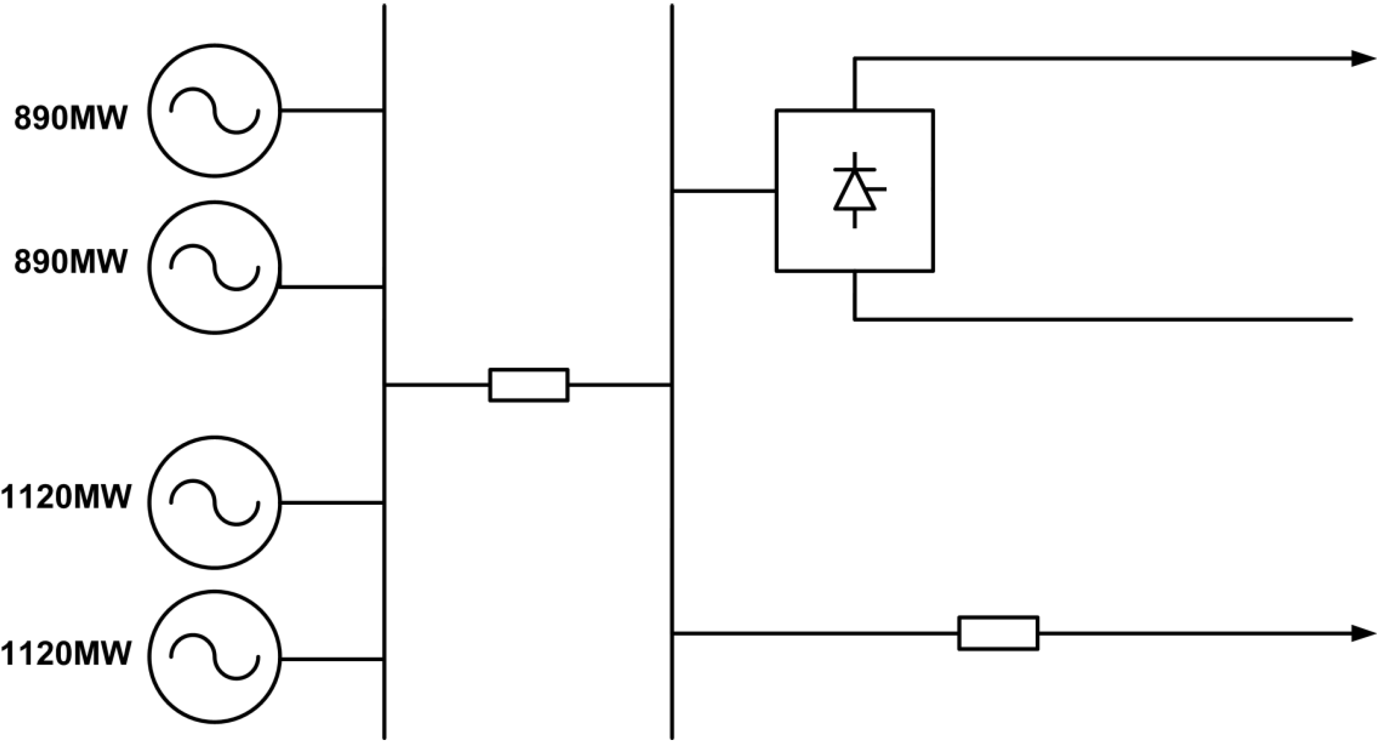
Now we take system #2 of the IEEE SSO second benchmark model (SBM) [13] as an example to verify the above analysis. In this system, there are two non-identical generators operating in parallel. Generator A (600 MVA), with four masses in its shaft, has mechanical natural frequencies of 24.65 Hz, 32.39 Hz and 51.10 Hz. Generator B (700 MVA), with three masses in its shaft, has mechanical natural frequencies of 24.65 Hz and 44.99 Hz. It can be seen that the two generators, though non-identical, share the common natural frequency of 24.65 Hz. The detailed mechanical data of the shaft system of the generators are shown in Table 1 and Table 2. The modal inertias of the generators under their common natural frequency, 24.65 Hz, are shown in Table 3. This example is representative and we now calculate its modal shapes.
Table 1. Mechanical data for Generator A.
MassInertia lbm∙ft2Damping lbf∙ft∙sec/radSpring Constant in lbf∙ft/rad
Exciter13834.34.39e6
Generator176,204547.997.97e6
Low-pressure turbine310,729966.250.12e6
High-pressure turbine49,912155.2
Table 2. Mechanical data for Generator B.
MassInertia lbm∙ft2Damping lbf∙ft∙sec/radSpring Constant in lbf∙ft/rad
Generator334,914208.2156.1e6
Low-pressure turbine370,483230.4198.7e6
High-pressure turbine109,92268.38
Table 3. Modal inertias of the generators under their common natural frequency.
GeneratorModal Inertia (p.u.)Rated Capacity (MVA)
A1.55600
B2.495700
As has been pointed out, the equivalent electrical stiffness coefficients, s eA , s eB and s em , whose magnitudes are well separated with those of mechanical ones, have no great impact on the modal shapes of the system. Approximately, in our calculation, we take s em = V A V B / ( X tA + X tB ) ( V A , V B are the terminal voltage magnitudes of the two generators and X tA , X tB are the leakage reactances of their transformers) and s eA = s eB = 0.5 s em .
With the data above we can obtain the state equations of this system and carry out eigenvalue analysis to calculate the frequency and mode shape of each oscillation mode. The calculation result is shown in Table 4. In Table 4, each row represents the right-eigenvector of an oscillation mode, which is also the mode shape of the corresponding mode. As the eigenvalues and eigenvectors appear in conjugate pairs, only those with a positive imaginary part are displayed. From the first and second row of Table 4, it can be seen that there are both a common-mode and an anti-mode, in which both generators participate, under the shared natural frequency of the two generators. The frequencies of common-mode and anti-mode are near to each other. The first row of Table 4 corresponds to the common-mode, whose eigenvector reveals that the generator masses of the two generator shafts oscillate almost in-phase. The second row of Table 4 corresponds to the anti-mode, whose eigenvector reveals that the generator masses of the two generator shafts oscillate almost out-of-phase. Apart from the above two modes, the remaining three modes are all the natural modes of one of the generators. As the frequencies of those three modes are well separated with each other, it can be seen from their eigenvectors that only the corresponding generator participates in oscillation.
Table 4. Eigenvalue result of the equivalent double-generator system.
EigenvalueFrequency/HzMode Shape (right-eigenvector)
Masses in Generator AMasses in Generator B
ω HPA ω LPA ω GenA ω ExcA ω HPB ω LPB ω GenB
−0.03 + j155.224.70.500 + j0.0000.127 + j0.000−0.366 + j0.000−0.479 + j0.0000.400 + j0.0060.234 + j0.003−0.394 − j0.006
−0.04 + j157.025.00.596 + j0.0000.141 + j0.000−0.434 + j0.000−0.573 + j0.000−0.215 + j0.003−0.124 + j0.0020.217 + j0.003
−0.05 + j203.632.4−0.890 + j0.0000.252 + j0.000−0.194 + j0.000−0.327 + j0.000−0.002 + j0.0000.000 + j0.0000.003 + j0.000
−0.03 + j282.845.00.000 + j0.0000.000 + j0.000−0.001 − j0.000−0.004 + j0.0000.933 + j0.000−0.350 − j0.0000.081 + j0.000
−0.05 + j321.151.10.000 − j0.000−0.001 + j0.0000.010 − j0.000−1.000 + j0.000−0.000 + j0.0000.000 − j0.000−0.000 + j0.000
For the anti-mode, we obtain that the oscillation amplitude ratio of the two generators is:
ω GenA / ω GenB = 0.434 / 0.217 = 2.00
On the other hand, referring to Table 3, the ratio of the modal inertias of the two generators under the common natural frequency is:
M B / M A = 2.495 * 700 1.55 * 600 = 1.88
Thus, the conclusion that in anti-mode, the oscillation amplitudes of the two generators masses are reversely in proportion to the corresponding modal inertias is basically valid. The reason why there is an error is that the equivalent electrical stiffness coefficients, s eA , s eB , and the modal damping coefficients slightly influence the frequencies and modal shapes of the oscillation modes.
In reference [11], it is shown that the phase relationship and relative amplitude of the generator masses in common-mode and anti-mode are also very dependent on the presence of series capacitors, especially when the electrical natural frequency matches the mechanical one. This is because under this condition, the magnitude of the electrical damping coefficient may become very large and have a noticeable impact on the oscillation modes of the system. In this paper, however, we mainly treat systems without series capacitors so that a resonance condition will not occur. Hence the statement that the electrical system has no great impact on the oscillation modal shapes can be considered reasonable.
In addition, we mention that for situations of two identical generators operating in parallel, as the modal inertias of the two generators under each common natural frequency are the same, the oscillation amplitudes of the two generator masses in each anti-mode are also the same, which can be regarded as a special case of the above reversely proportional relationship.

3.2. Phase Relationship of the Speed Deviation Signals of Two Generators Operating in Parallel Under Their Common Natural Frequency

As has been shown, the phase relationship of the speed deviation signals of the generators under their common natural frequency is a key consideration for SSDC design. For two generators operating in parallel, under their common natural frequency there exist both a common-mode and an anti-mode. In the actual oscillation, the speed deviation signal will be the addition of both of these two modes. If the anti-mode is hardly excited, the speed deviations will contain mostly the common-mode component, and the speed deviation signals of the two generators will be in-phase. On the other hand, if the common-mode is hardly excited, the speed deviations will contain mostly the anti-mode component, and the speed deviation signals of the two generators will be out-of-phase. More generally, however, if both the common-mode and the anti-mode are simultaneously excited, then there will be an uncertain phase relationship between the speed deviation signals of the two generators.
As we know, the extent to which mode k of a system is excited depends on:
c k = Ψ k X 0
where Ψ k is the left eigenvector corresponding to mode k and X 0 is the initial value of the state variables of the system [14].
For situations where two identical generators, generator A and generator B, operating in parallel, and assume that they deliver the same power, then for anti-mode k of the system, we have:
Ψ k = [ Ψ kA Ψ kB ] = [ Ψ kA Ψ kA ]
and:
X 0 = [ X 0 A X 0 B ] t = [ X 0 A X 0 A ] t
Apparently, now c k = 0 , namely, the anti-mode of this system would not be excited. This is exactly the reason why in this system, the speed deviation signals of the two generators will be in-phase.
If the two identical generators do not deliver the same power, then Equations (9) and (10) will hold not exactly but approximately, so that in this situation we have c k 0 ; namely, the anti-modes will be excited slightly. Hence the speed deviation signals of the two generators will almost be in-phase.
Finally, for situations of two non-identical generators operating in parallel, the parameters of the generators are no longer the same; the oscillation amplitudes of the shaft masses in the anti-mode may be different and even the number of shaft masses of the two generators may differ. As a result, Equations (9) and (10) will no longer hold and we have c k 0 ; namely, the anti-mode of the system may be excited. As the extent to which the common-mode and the anti-mode are excited is uncertain, the phase relationship of the speed deviation signals of the two generators will also be uncertain.
In reference [10], it is shown that when two identical generators operate in parallel, the speed deviation signals of the two generators will be in-phase and the two generators can be represented by a single equivalent generator. In reference [15], it is shown that if the two identical generators do not deliver the same power, then there will be a slight phase difference, which is generally no more than 40°, between the speed deviation signals of the two generators. These observations are consistent with the above analysis we have made. In this paper, whether there will be a definite phase relationship between the speed deviation signals of the generators, regardless of whether they are identical or non-identical, is demonstrated to be dependent on the extent to which the anti-mode of the system is excited.
In addition, there is one more issue to mention. The frequencies of the common-mode and the corresponding anti-mode will be very close but not exactly the same. Hence, when the common-mode component and the anti-mode component are added, a phenomenon called ‘beat’ will arise, namely, the amplitude of the resultant signal will oscillate at a very low frequency. This phenomenon is common. For instance, we may sometimes observe that the amplitude of a decaying oscillation can temporarily increase even though there is no negative damping in the system. In SSDC design, most attention is paid to the phase relationship of the signals, and the ‘beat’ phenomenon does not have a noticeable impact.

3.3. SSDC Design Based on Mode Separation

As has been demonstrated in Section 3.2, for systems with two non-identical generators operating in parallel, the phase relationship of the speed deviation signals of the two generators under their common natural frequency is uncertain. However, as has been shown in the beginning of this section, if the phase relationship of the speed deviation signals of the generators is uncertain, it can hardly be guaranteed that the SSDC is capable of providing a positive damping for all the generators simultaneously. Hence, simply taking the original speed signals of the generators as the input signal of SSDC is infeasible.
The reason why there is an uncertain phase relationship between the speed deviation signals of the generators is that during the oscillation, the common-mode and the anti-mode are simultaneously excited. As the anti-mode represents the local interaction of the two generators, it does not couple with the HVDC system. Hence, under the impact of the mechanical damping of the generator shafts, the anti-mode is inherently stable. That is to say, only the common-mode may be influenced by the HVDC system and become unstable. Hence, in the input signal of SSDC, we can eliminate the anti-mode component and only reserve the common-mode component, so that the anti-mode and the common-mode are separated and the SSDC is used for common-mode damping. As in the common-mode, the speed deviation signals of the generators have the definite in-phase relationship; it is totally possible that the SSDC can provide positive damping for all the generators simultaneously.
As has been demonstrated in Section 3.1, in anti-mode, the oscillation amplitudes of the generators are reversely in proportion to their modal inertias. Denoting the modal inertias of the generators under their common natural frequency as M A and M B 
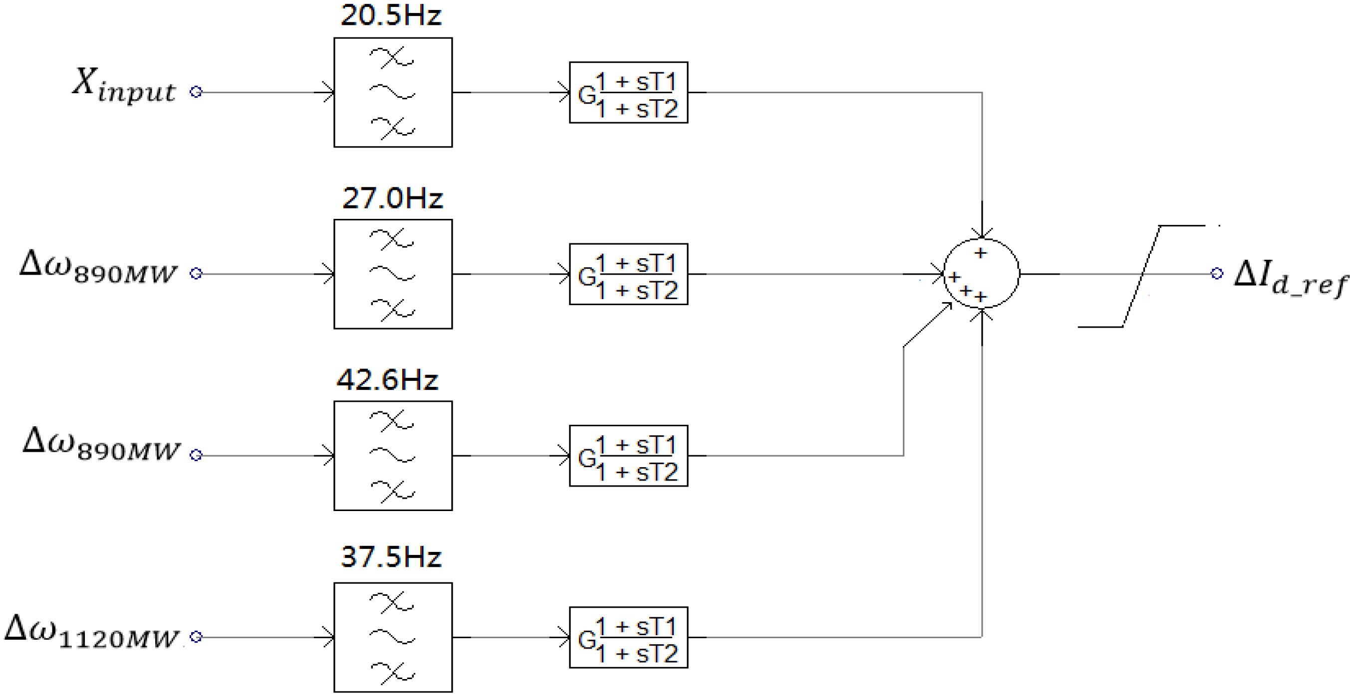
, then the input signal of the SSDC can be taken as:
X input = ( M A ω A + M B ω B ) ( M A + M B )
where M A + M B is the coefficient for normalization, in case that a large gain in the signal may bring adverse effect to the system stability. In this input signal, the anti-mode component under the common natural frequency of the generators will be almost eliminated and the common-mode component will be reserved. Apart from the common natural frequency, the oscillation components of the other natural frequencies of the generators are also reserved in their speed deviation signals.
Admittedly, the relationship that the oscillation amplitudes of the generators in anti-mode are reversely in proportion to their modal inertias does not hold exactly. Hence, in the input signal of SSDC, the anti-mode component cannot be eliminated totally. However, the common-mode component will be the dominant part so that the in-phase relationship of the speed deviation signals of the generators will not get be influenced much.

4. Case Study

In this section, a typical example is adopted to illustrate the design process of SSDC for multi-generators and its effectiveness is verified through time-domain simulation.

4.1. Introduction of the Example Studied

The electrical network representation of the example studied is shown in Figure 5. In this example, there are four generators in two types, the capacities of which are 2 × 1120  MW + 2 × 890  MW . The four generators operate in parallel. The rated capacity of the HVDC system is 1500 MW. The remaining output power of the generators are sent out through an AC transmission line (without serious compensation).
Figure 5. Electrical network representation of the case studied.
Energies 08 01644 g005
The shaft parameters of the generators in the example is determined according to the principle that they have the same per-unit value as those in system #2 of the IEEE Second SSO benchmark model. As a result, the 890 MW generators have natural frequencies of 20.5 Hz, 27.0 Hz and 42.6 Hz. The 1120 MW generators have the natural frequencies of 20.5 Hz and 37.5 Hz. The generators share the natural frequency of 20.5 Hz.

4.2. The Main Operating Conditions Under Consideration

To ensure that the SSDC is effective under various operating conditions, when obtaining the phase difference, TRI ( λ ) , between the induced additional electrical torque induced on the generators, Δ T ˜ e ( λ ) , and the current reference value deviation of the converter, I ˜ d _ ref ( λ ) by test signal method, the following five main operating conditions are considered:
(a)
The four generators and the HVDC system all deliver the rated power;
(b)
One of the 1120 MW generators is out of service and the remaining three generators and the HVDC system deliver the rated power;
(c)
One of the 890 MW generators is out of service and the remaining three generators and the HVDC system deliver the rated power;
(d)
The four generators deliver half of their rated power and the HVDC system deliver the rated power;
(e)
The four generators and the HVDC system all deliver half of the rated power.

4.3. SSDC Design

As is shown in Figure 2, the SSDC is of multi-modal structure. A band-pass filter is applied for each oscillation mode. The lead-lag block for each mode is used to compensate the phase difference, TRI ( λ ) , of the corresponding mode.
Now we take the 20.5 Hz mode, which the generators of both types share, as the illustration to explain the SSDC design method in detail.
Firstly, we obtain the phase difference, TRI ( λ ) , between the induced additional electrical torque induced on the generators, Δ T ˜ e ( λ ) , and the current reference value deviation of the converter, I ˜ d _ ref ( λ ) by test signal method, namely, we construct the studied modal in PACAD/EMTDC, then, a small test signal, I d _ ref = 0.05 sin ω t   p . u . , where ω = 2 π * 20.5  rad / s , the angular frequency under study, is applied. After carrying out time-domain simulation, we can obtain the induced electrical torques on the generators corresponding to the test signal in the simulation result. The result for operating condition (a), introduced in Section 4.2, is shown in Figure 6.
From Figure 6, we can obtain that the induced electrical torques, T e , lags the test signal, I d _ ref , about 17° under operating condition (a). Repeating the above procedure for operating conditions (b)–(e), we obtain that the phase differences for these conditions range from 16° − 19°. Hence, for this mode, to maintain that the condition 90 ° < S S D C ( λ ) + T R I ( λ ) < 90 ° is satisfied for all the five operating conditions considered, we can utilize a lead/lag stage to compensate 17° under 20.5 Hz. The phase-frequency characteristic of the lead/lag stage is shown in Figure 7.
Figure 6. The test signal, I d _ ref , and the corresponding electrical torques, T e , induced on the generators.
Energies 08 01644 g006
Figure 7. Phase-frequency characteristic of the lead/lag stage to compensate 17 under 20.5 Hz.
Energies 08 01644 g007
As has been demonstrated, in the input signal, the anti-mode component should be eliminated. Hence, the input signal is:
X i n p u t = X 890 M W ω 890 M W / ( M 890 M W + M 1120 M W )   + X 1120 M W ω 1120 M W / ( M 890 M W + M 1120 M W )
where M 890 M W is the modal inertia of 890 MW generator under 20.5 Hz and M 1120 M W is the modal inertia of 1120 MW generator under 20.5 Hz. ω 890 M W and ω 1120 M W are the speed deviation signals of the 890 MW and 1120 MW generators, respectively.
Finally, the proportion gain should be adjusted properly.
Now, the detailed process of SSDC design for the 20.5 Hz mode has been introduced. The design method for the other modes is similar. However, as the other modes are not shared by all the generators, we do not need to take the combination of the speed signals as the input signal. Instead, we just take the speed signal of the corresponding generator as the input signal.
In addition, to maintain that the action of SSDC does not affect the normal operation of the HVDC system, the output signal of SSDC, I d _ ref , is limited within ± 0.05  p . u . by a limiter. The whole structure of the SSDC is depicted in Figure 8.
Figure 8. Whole structure of the SSDC.
Energies 08 01644 g008

4.4. Time-Domain Simulation

The example model shown in Figure 5 is constructed in PSCAD/EMTDC. The operating condition that the generators and the HVDC system all deliver the rated power (Operating condition a) is taken as the example. After the system goes into steady state, a three-phase-to-ground fault is applied on bus B shown in Figure 5. The fault lasts for 0.1 s. Figure 9 shows the torques and speeds of the generators without the SSDC applied. From Figure 9, we can see that the system is not stable. Moreover, utilizing a band-pass filter, we can obtain the 20.5 Hz components of the generator speed signals during the oscillation, as is shown in Figure 10. From Figure 10a, at the start of the oscillation, the 20.5 Hz components of the generator signals have an uncertain phase relationship because the resultant signals are the sum of both the common-mode and the anti-mode. However, after some time, as the anti-mode part damps out, only the common-mode part remains and the signals are in-phase, as is shown in Figure 10b. These observations are in agreement with the analysis made in the Section 3.
Figure 9. Torques and speeds of generators when SSDC is not applied.
Energies 08 01644 g009
Figure 10. The 20.5 Hz components of the generator speed signals (a) at the start of the oscillation and (b) after some time.
Energies 08 01644 g010
Then the SSDC is applied and the torques and speeds of generators now is shown in Figure 11, from which we can see that the SSDC is effective in mitigating the oscillation. Figure 12 shows the output signal, I d _ ref , of SSDC. With the action of the limiter, the output signal of SSDC is limited within ± 0.05  p . u . so that it will not affect the normal operation of the HVDC system.
Figure 11. Torques and speeds of generators when SSDC is applied.
Energies 08 01644 g011
Figure 12. Output signal, I d _ r e f , of SSDC during its action.
Energies 08 01644 g012
Finally, if we take the speed signal of only one type of the generators as the input signal of the 20.5 Hz mode, instead of the combination of the speed signals (Equation (12)) of all the generators, the oscillation will still not be mitigated, as is shown in Figure 13. This result verifies the necessity of taking the combined signal as the input signal of SSDC, as suggested by this paper.
Simulation under other operating conditions has similar results.
Figure 13. Generator speeds while speed of only one type of generator is taken as the input signal of the 20.5 Hz mode of SSDC.
Energies 08 01644 g013

5. Conclusions

This paper studies the SSDC design when there are multiple generators near HVDC converter stations. SSDC design for multi-generator systems is more complex than for single-generator systems, especially when the generators have common mechanical natural frequencies. The phase relationship of the speed deviation signals of the generators under their common natural frequencies is a key consideration for SSDC design. This paper investigates the phase relationship of the speed deviation signals of two generators operating in parallel under their common natural frequency. The result shows that whether the two generators are identical or not, under the common natural frequency, there will be both a common-mode and an anti-mode. In the anti-mode, the generator masses of the two shafts will oscillate almost out of phase, and the oscillation amplitudes of the generator masses are nearly reversely in proportion to the corresponding modal inertias. Due to that both the common-mode and the anti-mode will be excited simultaneously during oscillation, the phase difference of the speed deviations of the two generators will be uncertain, so that taking the speed signal of either generator as the input of the SSDC will hardly guarantee its effectiveness in mitigating oscillation of both generators. Furthermore, this paper points out that as the anti-mode is mainly due to the local interaction of the generators and does not couple with the HVDC system; it is inherently stable. By appropriate linear combination of the speed signals of the generators, the anti-mode component can be eliminated and only the common-mode component will be left. This combined signal is taken as the input signal of SSDC. As the common-mode signal of the generators are in-phase, so that they have a definite phase relationship, design of SSDC becomes feasible and the effectiveness of SSDC can be guaranteed. The design process of SSDC is illustrated by a multi-generator system and its effectiveness is verified by time-domain simulation.

Acknowledgments

The work of Shen Wang and Zheng Xu was supported in part by the National High Technology Research and Development Program of China (863 Program) (No. 2011AA05A119) and in part by the Major Projects on Planning and Operation Control of Large Scale Grid of the State Grid Corporation of China (No. SGCC-MPLG001-031-2012).

Author Contributions

Shen Wang and Zheng Xu conceived and developed the ideas behind the present research. Shen Wang carried out the theoretical analysis and case study and wrote the paper under supervision of Zheng Xu. Final review, including final manuscript corrections was performed by Zheng Xu.

Conflicts of Interest

The authors declare no conflict of interest.

References

  1. Bahrman, M.; Larsen, E.V.; Piwko, R.J.; Patel, H.S. Experience with HVDC—Turbine-generator torsional interaction at square butte. IEEE Trans. Power Appar. Syst. 1980, PAS-99, 966–975. [Google Scholar]
  2. Piwko, R.J.; Larsen, E.V. HVDC system control for damping of subsynchronous oscillations. IEEE Trans. Power Appar. Syst. 1982, PAS-101, 2203–2211. [Google Scholar]
  3. Harnefors, L. Analysis of subsynchronous torsional interaction with power electronic converters. IEEE Trans. Power Syst. 2007, 22, 305–313. [Google Scholar] [CrossRef]
  4. Zhou, C.C.; Xu, Z. Damping analysis of subsynchronous oscillation caused by HVDC. In Proceedings of the 2003 IEEE PES Transmission and Distribution Conference and Exposition, Dallas, TX, USA, 7–12 September 2003; pp. 30–34.
  5. Hong, C.; Rao, H. The study of SSTI between Guizhou-Guangdong II ±500 kV DC transmission link and steam-turbine-generators near the rectifier terminal. In Proceedings of the 2006 International Conference on Power System Technology, Chongqing, China, 22–26 October 2006; pp. 1–6.
  6. Song, R.; Lin, J.; Ban, L.; Xiang, Z. Study on the SSO damping characteristic and damping control of Mongolia-China HVDC transmission system. In Proceedings of the 2010 International Conference on Power System Technology, Hangzhou, China, 24–28 October 2010; pp. 1–5.
  7. Jiang, Q.Y.; Cao, Y.J.; Cheng, S.J. A genetic approach to design a HVDC supplementary subsynchronous damping controller. IEEE Trans. Power Deliv. 2005, 20, 1059–1064. [Google Scholar] [CrossRef]
  8. Kim, D.J.; Nam, H.K.; Moon, Y.H. A practical approach to HVDC system control for damping subsynchronous oscillation using the novel eigenvalue analysis program. IEEE Trans. Power Syst. 2007, 22, 1926–1934. [Google Scholar] [CrossRef]
  9. Tang, N.; Xiao, X.; Zhang, J.; Xu, Y.; Li, Q. A phase correction method of HVDC supplementary subsynchronous damping controller. In Proceedings of the 10th IET International Conference on AC and DC Power Transmission (ACDC 2012), Birmingham, UK, 4–5 December 2012; pp. 1–5.
  10. Alden, R.T.H.; Nolan, P.J.; Bayne, J.P. Shaft dynamics in closely coupled identical generators. IEEE Trans. Power Appar. Syst. 1977, 96, 721–728. [Google Scholar] [CrossRef]
  11. Jennings, G.D.; Harley, R.G. Torsional interaction between nonidentical turbine generators. IEEE Trans. Power Syst. 1990, 5, 133–139. [Google Scholar] [CrossRef]
  12. Xu, Z.; Feng, Z. A novel unified approach for analysis of small-signal stability of power systems. In Proceedings of the IEEE Power Engineering Society Winter Meeting, Singapore, Singapore, 23–27 January 2000; pp. 963–967.
  13. IEEE SSR working group. Second benchmark model for computer simulation of subsynchronous resonance. IEEE Trans. Power Appar. Syst. 1985, PAS-104, 1057–1066. [Google Scholar]
  14. Kundur, P. Power System Stability and Control; McGraw-Hill: New York, NY, USA, 1994. [Google Scholar]
  15. Iravani, M.R. Torsional oscillations of unequally-loaded parallel identical turbine-generators. IEEE Trans. Power Syst. 1989, 4, 1514–1524. [Google Scholar] [CrossRef]

