Article

Nanoparticle Filtration Characteristics of Advanced Metal Foam Media for a Spark Ignition Direct Injection Engine in Steady Engine Operating Conditions and Vehicle Test Modes

1
School of Mechanical Engineering, Korea University, 145, Anam-ro, Seongbuk-gu, Seoul 136-701, Korea
2
Alantum Corporation, 8F, Starwood B/D, 5439-1, Sangdaewon 2-dong, Joongwon-gu, Seongnam-city, Gyonggi-do 462-819, Korea
*
Author to whom correspondence should be addressed.
Energies 2015, 8(3), 1865-1881; https://doi.org/10.3390/en8031865
Submission received: 18 November 2014 / Revised: 13 February 2015 / Accepted: 28 February 2015 / Published: 9 March 2015

Abstract

:
In this study, the particle formation and reduction characteristics at the engine-out position, after a three-way catalyst (TWC) and a metal foam gasoline particulate filter (GPF), were evaluated for a gasoline direct-injection (GDI) engine under part-load operating conditions. The vehicle tests were performed under the Federal Test Procedure-75 (FTP-75) and the Highway Fuel Economy Test (HWFET) modes. Particle number (PN) concentrations, size distributions, and the filtering efficiency with the GPF were evaluated with a condensation particle counter (CPC) and a differential mobility spectrometer (DMS500). Under steady engine operating conditions, the PN concentrations at the engine-out position were 9.7 × 10⁵–2.5 × 10⁶ N/cc. While, the PN concentrations after the GPF were 9.2 × 10⁴–3.5 × 10⁵ N/cc, and the PN was reduced by 77%–96%. The PN filtering efficiency with the GPF-GDI vehicle reached approximately 58% in the FTP-75 and 62% in the HWFET mode. The PN concentration of the GPF-GDI vehicle was significantly reduced to 3.95 × 10¹¹ N/km for the FTP-75 and 8.86 × 10¹⁰ N/km for the HWFET mode. The amount of nucleation mode particles below 23 nm was substantially reduced with the GPF-GDI vehicle. The fuel economy, CO2, and regulated emissions of the GPF-GDI vehicle were equivalent to those of the base GDI vehicle under the vehicle certification modes.

1. Introduction

To meet current and projected stringent global greenhouse gas (GHG) regulations and the fuel economy standards, vehicle manufacturers have been developing energy-efficient gasoline direct-injection (GDI) technologies for spark ignition (SI) engines [1,2,3]. State-of-the-art GDI engines combined with boosting technology offer higher specific power, lower fuel consumption and faster response than conventional port fuel injection (PFI) engines [3,4,5,6,7]. In spite of these many advanced technologies, many studies have indicated that the mixture preparation schemes and combustion mechanisms of the GDI engine emit significantly higher amounts of particulate matter (PM) than the traditional PFI engines or diesel engines that have been equipped with particulate filters, especially during the cold-start phase and at high acceleration points [5,6,8,9,10,11,12,13,14,15]. The fuel impingement on the piston bowl and the cylinder liner is responsible for particle formation, so comprehensive approaches or optimization of the injector location, the combustion chamber shape, and improved engine control strategies need to be considered to reduce the formation of nanoparticles in GDI engines [16,17,18,19,20]. PM pollutants are currently of considerable interest because medical findings have indicated that exposure to ultrafine aerosol particles (<100 nm diameter) from internal combustion engines cause significant health risks [7,8,21,22,23,24]. Furthermore, previous studies have indicated that GDI engines produce considerably hazardous nucleation mode particles, which are typically a complex mixture of solid and more volatile particles [8,17,18,25,26,27,28]. Based on the high market growth of GDI vehicles, the European Union (EU) has regulated the particle number (PN) standard for GDI vehicles, which considers non-volatile particles with a diameter above 23 nm, in the Euro-6 vehicle emissions standards [18,20,21,24]. Additionally, the California Air Resource Board (CARB) is debating future PM emission regulations for the low-emission vehicle (LEV)-III standards. CARB has revealed that sub-23 nm particles comprise a substantial portion of the total PM emissions from GDI vehicles [5,9,21,29,30]. The primary reason for these controversial findings of differences between the particle measurement programme (PMP) methods and CARB relates to the sensitivity of the sampling and dilution approaches for the secondary particles formed from gaseous precursors [29,30,31,32].
The particle reduction characteristics of the spark ignition direct injection (SIDI) engine with a three-way catalytic converter (TWC) have been well investigated in previous studies [33,34,35]. Substantial reduction of the sub-23 nm particles was observed in the downstream position of the TWC. The reduction mechanism of particles through the catalytic converter was categorized as partly due to oxidation and partly to coagulation [35]. Engine-out particles consist of combustion-generated solid carbon particles and some organic compounds [7,8,9,18,21]. The solid particles become coated with condensed and adsorbed organic compounds, including unburned hydrocarbons and oxygenated hydrocarbons [8,25,26,27,29,30]. Particle size distributions are generally classified into three modes: nucleation mode (5 nm < dp < 30 nm), accumulation mode (30 nm < dp < 1000 nm) and coarse mode (1000 nm < dp). Exhaust particles containing volatile organic compounds that are less than 23 nm in size formed during combustion in locally rich regions are substantially oxidized in the TWC, while almost all of the accumulation mode particles are passed through the catalyst without purification [25,27,33,34,35]. Therefore, a cost-effective gasoline particulate filter (GPF) can be adopted for GDI vehicles to reduce the nano-PM emissions to satisfy future PN emission regulations [10,27,29,30,31,36,37,38,39]. The physical characteristics of volume, space velocity, pressure drops, exhaust temperature for natural regeneration, and particle-filtering efficiency, including sub-23 nm particles that do not negatively affect vehicle exhaust emissions and fuel efficiency, should be considered for optimized performance [5,10,25,27,30,36,37,38,39,40,41,42,43].
The purpose of this study is to evaluate the size-resolved PN concentrations, filtration efficiency, and pressure drops of the metal foam-type GPF for the GDI engine in the part-load conditions and the relevant engine control parameters. In verification tests on light-duty vehicles, different driving cycles were conducted for various emission certification modes in accordance with the federal test procedure-75 (FTP-75) and the highway fuel economy test (HWFET). Finally, size-resolved particle concentration by DMS500 was included to investigate the proportion of sub-23 nm nucleation mode and accumulation mode particles from GDI and GDI-GPF vehicles, respectively.

2. Experimental Apparatus

2.1. Test Engine and Vehicle

Table 1 provides detailed specifications of the test 2.4 liters naturally aspirated (NA) GDI engine and vehicle. A direct-injection spark ignition engine with a compression ratio of 11.3:1 was tested. A two-brick under-floor catalytic converter (UCC) combined with the engine control strategies of double split injection (DSI) and spark timing retard was used to effectively lower the vehicle emissions during the cold-start phase. A metal foam-type GPF (Alantum, Seongnam, Korea), located 50 cm downstream from the outlet of the UCC, was applied to the test vehicle to evaluate the nanoparticle filtration efficiency of the GPF [39].
Table 1. Specifications of test engine and vehicle.
TypeNaturally aspirated engine stoichiometric direct injection
Displacement (cc)2359
Bore × Stroke (mm)88 × 97
Compression ratio11.3:1
Valvetrain deviceDual continuously variable valve timing
Fuel injection systemCamshaft-driven high pressure pump Wall mounted injector Split injection during cold start
Exhaust systemUnder-floor catalytic converter
Catalyst heating logicSpark timing retard during cold start
Transmission6 speed automatic transmission
Particle size distributions and PN concentrations from the GDI engine were directly measured at three positions with heated sampling valves and sampling line for minimizing the loss of particles: (1) in front of the TWC position; (2) after the TWC position; and (3) after the GPF position using a differential mobility spectrometer (DMS500, CAMBUSTION, Cambridge, UK). The DMS500 equipped with heated sample line and two stage dilution systems allowed direct sampling from the exhaust gas. The detectable particle size ranges of this equipment were 5–1000 nm and the time response was 200 milliseconds [18,33,34,35]. The specifications of the tested fuel are presented in Table 2.
Table 2. Properties of the gasoline fuel.
PropertiesValue
RON93.2
Vapor pressure @ 37.8 °C (kPa)70.9
Density @ 15 °C (kg/m3)718
Sulphur content (mg/kg)5
Oxygen (wt%)2.02
Aromatic (vol%)15.7
Benzene (vol%)0.49
Low heating value (J/g)41,120
Distillation temperature (°C)10 vol%49
50 vol%74
90 vol%144

2.2. Gasoline Particulate Filter and the Filtration Mechanism
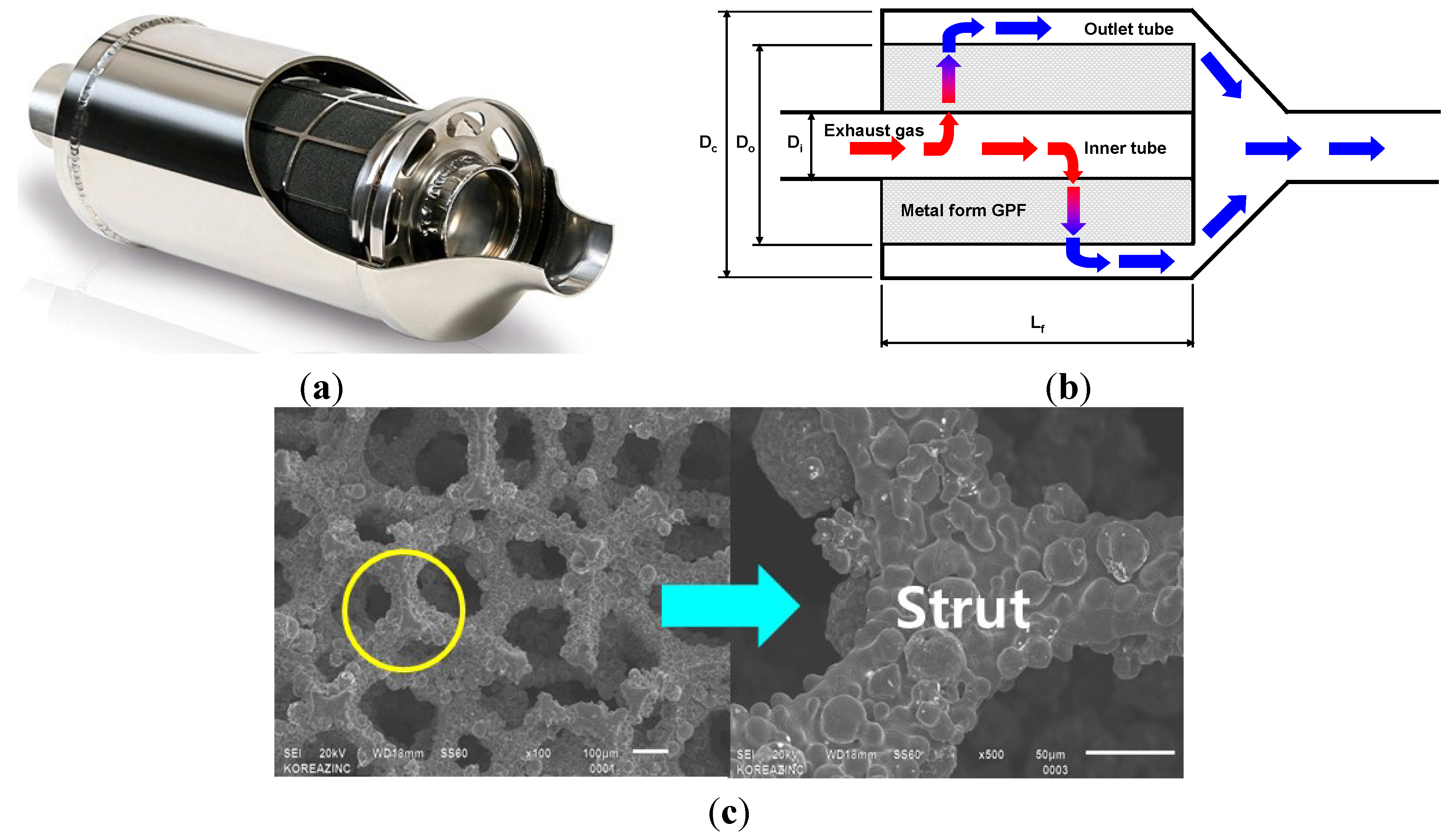
Figure 1 shows a schematic diagram of the cross-sectional area of the metal foam-type particulate filter. The metal foam has the shape of a circular annular tube, and exhaust gas flows radially from the inside to the outside of the annular tube. Metal foams have various advantages for use as filter media and substrates in internal combustion engines [38,39]. First, metal foams of various pore sizes, from 450 to 1200 micron, can be produced and the resulting porosities range around 85%–95%.
Figure 1. Geometry of a radial type metal foam filter for GDI engine; (a) external appearance of the metal foam GPF; (b) exhaust gas flow and the geometry of the GPF; (c) images of metal foam.
Energies 08 01865 g001
The pressure drops and PN loading capacity with various metal foam media depends on pore sizes and volume. Therefore, when metal foams with various pore sizes were fabricated into one filter, the particle capturing process inside the filter pore would be more uniformly improved, and the pressure drop through the GPF could be decreased in as a necessary [36,37,38,39]. Moreover, metal foam has a three-dimensional complex pore structure and an irregular strut surface because of the unique powder metallurgical manufacturing processes. These processes form a large surface area, which enhances the mass transfer from the main flow to the strut surface. Therefore, the catalytic performance for exhaust gas treatment can be increased when metal foam is applied as a catalyst substrate [34,36,37,38,39,40,41,42]. Table 3 shows the physical properties of the metal foam filter used in this test, with a total volume of 4.0 liters, a length of 280 mm, an inner diameter of 42.7 mm; an outer diameter of 142 mm and a total diameter of 160 mm with fixture and outer canning for the GPF.
Table 3. Representative properties of the metal foam filter.
Metal foam propertyOuter layer3rd layer2nd layerInner
Nominal pore size (micron)4505808001200
Porosity (%)87889093
Specific surface area (m2/L)12.710.88.667.31
Strut hydraulic diameter (μm)54546073
Foam density (g/cm3)0.6950.5810.4480.351

2.3. Vehicle Test Equipment and Particulate Emission Analysis

Figure 2 shows a schematic diagram of the experimental apparatus that was used to analyze the concentrations of nano-PM and the regulated emissions for vehicle mode tests. A 48-inch single roll chassis dynamometer (M4500, AVL, Graz, Austria), a gaseous emission analyzer (MEXA-7200H, Horiba, Kyoto, Japan) and a full-flow CVS exhaust dilution tunnel system (CVS-7200S and DLT-1230, Horiba) measured the particle emissions, regulated emissions, carbon dioxide (CO2), and fuel economy. Fluorocarbon-coated glass filters (TX40, Pallflex, Port Washington, NY, USA) were used to collect particulates, which were measured using an analytical balance (CPA2P-F, Sartorius, Göttingen, Germany).
The PN concentration emitted from the test vehicle was counted via a system corresponding to the golden particle measurement system (GPMS) standards, recommended by the PMP [29,30,32,39]. The system has two primary components: (1) a particle sampler system consisting of a sampling and a particle pre-classifier (cyclone with d50% = 2.5 μm); and (2) a particle conditioning and measurement system consisting of a volatile particle remover (VPR) and a particle number counter (PNC) unit. The VPR provides heated dilution, thermal conditioning of the sample aerosol, and secondary dilution for cooling and freezing of the sample before it enters into the PNC [34,35]. The PNC unit is a condensation particle counter (CPC 3010D, TSI, Shoreview, MN, USA) with the lower cut-off modified to 23 nm. Additionally, a DMS500, which is a fast-response size spectrometer, was installed at the tail pipe location of the vehicle under FTP-75 and HWFET mode to analyze the PN concentration and size distribution characteristics [16,18,24,29].
Figure 2. Schematic diagram of the vehicle test system.
Energies 08 01865 g002

3. Experimental Results and Discussion

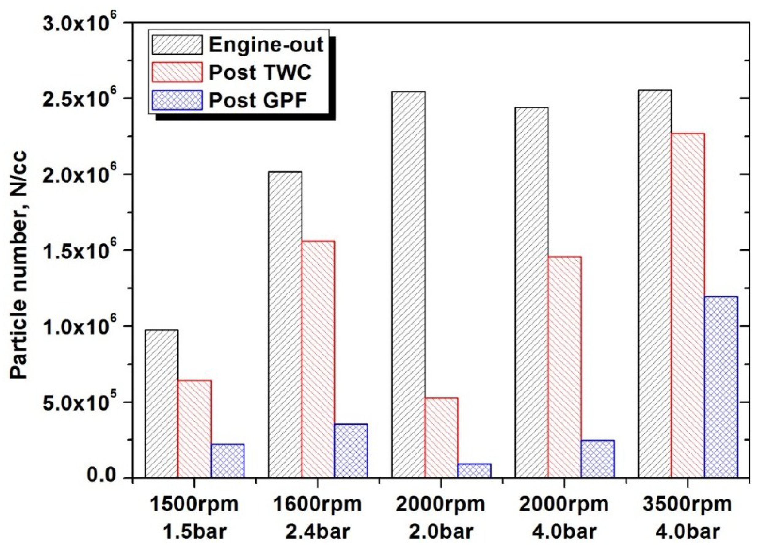
3.1. Exhaust System Temperatures, Pressure Drop, and PN Concentration at Part-Load Conditions

Various part-load engine operation conditions, which mainly occur in the FTP-75 and the HWFET driving cycles, were selected for this research. The exhaust system temperatures and pressure drop between the GPF of the tested engine are shown in Figure 3. To monitor the exhaust system temperatures of the engine, K-type thermocouples were installed at the exhaust port, at the catalyst bed (20 mm below the frontal face) and at the GPF (inlet and outlet positions) streamline. The exhaust port temperatures under part-load conditions of 1500 rpm at brake mean effective pressure (BMEP) of 1.5 bars and of 3500 rpm BMEP of 4.0 bars were 217 °C and 132 °C higher than those before the GPF sampling position, respectively. The temperatures at the inlet and the outlet of the GPF increased from 331 °C and 368 °C to 617 °C and 654 °C, and maintained an approximately 37 °C difference in the part-load conditions. Furthermore, the pressure drop in the GPF was less than 1.0 kPa in the three part-load conditions. However, the pressure drop increased by 3.9 kPa at 3500 rpm, BMEP 4.0 bars.
Figure 4 shows the total PN concentration of the GDI and the GDI-GPF engines in part-load conditions. The particle emissions from the GDI and the GDI-GPF engines were compared at three positions using the DMS500: (1) before the TWC; (2) after TWC; and (3) after the GPF. The total PN at the engine-out sampling position varied from 9.7 × 10⁵ N/cc to 2.5 × 10⁶ N/cc, and that emitted after the TWC sampling point was reduced by approximately 34% and 22% at low engine speed conditions, and by 79% at 2000 rpm, BMEP of 2.0 bars, and 11% at high engine speed conditions. The TWC effectively removed the volatile hydrocarbon particle precursors under low-speed, low-load conditions but had essentially a little effect on particle emissions under the high-speed and high-load conditions because of the higher exhaust flow rate [6,8,10,18,19,20,33,34,35].
Figure 3. Exhaust system temperatures and pressure drop of GPF in various part-load conditions; (start of injection (SOI), 300°–304° CA before top dead center (BTDC); Lambda = 1.0; spark advance (SA) = minimum spark advance for the best torque (MBT)).
Energies 08 01865 g003
Figure 4. Total particle numbers with GDI and GPF-GDI engine in various part-load conditions; (start of injection (SOI), 300°–304° CA before top dead center (BTDC); Lambda = 1.0; spark advance (SA) = minimum spark advance for the best torque (MBT)).
Energies 08 01865 g004
In the low exhaust gas temperature conditions, the nanoparticles exhibited relatively low Brownian motion intensity [7,8,9,36,37,38,39], and therefore, had a low probability of colliding and adhering to the GPF structure. When the gas temperature and exhaust flow velocity increase at high speed and high load conditions, particles are blocked and rebounded at the pore structure, so the filtering efficiency becomes higher compared to the lower exhaust gas temperature conditions [39]. Consequently, the total PN after the GPF sampling position was 2.2 × 10⁵ N/cc, and the reduction of particle concentration at 1500 rpm, BMEP of 1.5 bars was 77% compared to the amount emitted from the engine-out position. However, the collection efficiencies at 2000 rpm, BMEP 2.0 bars and 4.0 bars part-load conditions were greater than 90%, when the GPF inlet temperature exceeded 400 °C. The amount of exhaust particles in the engine-out position increased sharply with the higher engine speed and load. However, substantial reduction of particle concentration was attained after the TWC and GPF positions, which were mainly associated with the oxidation and storage process of the volatile compounds and solid particles in the exhaust after-treatment systems [33,34,35,39,40,41,42].

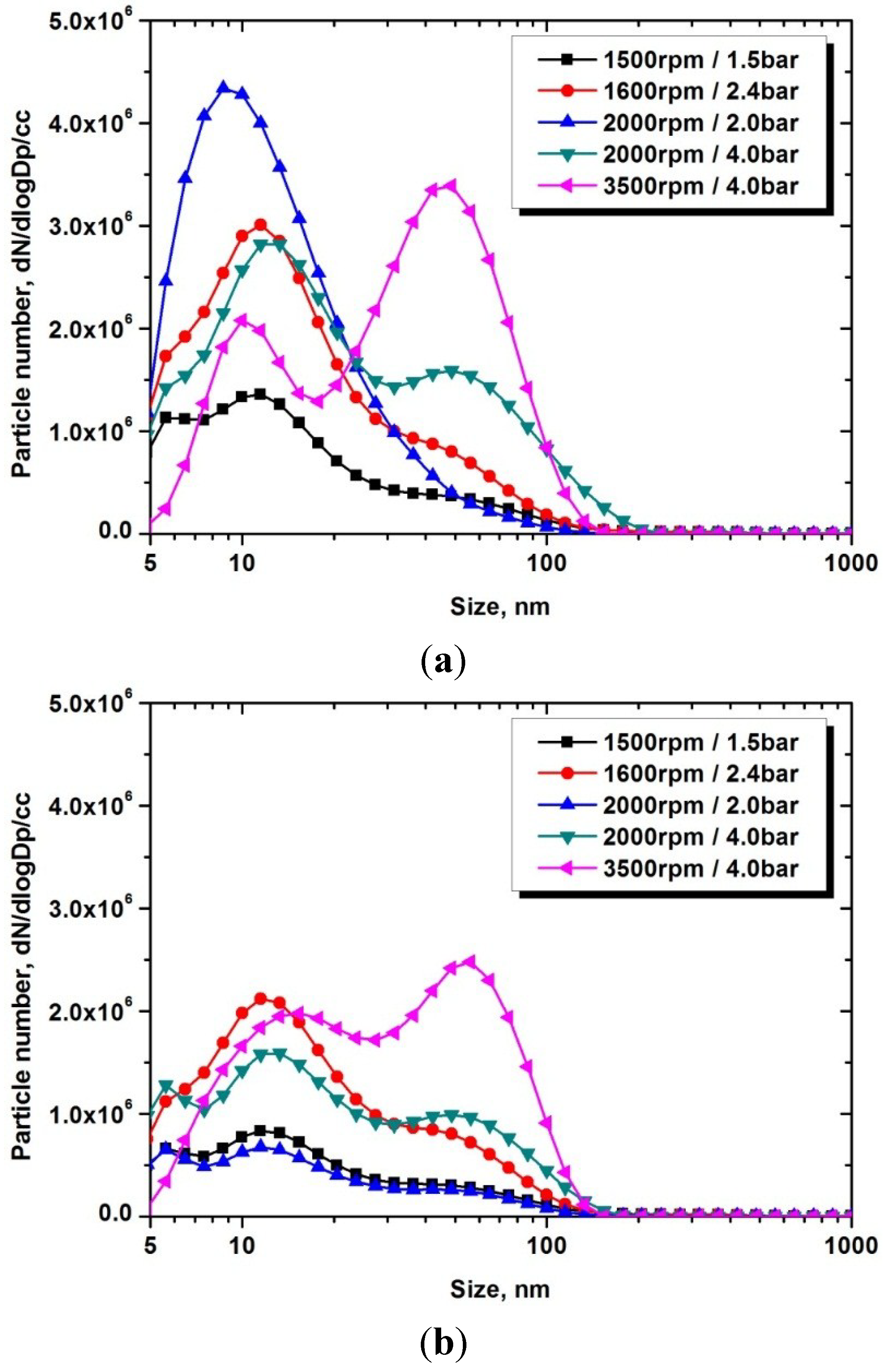
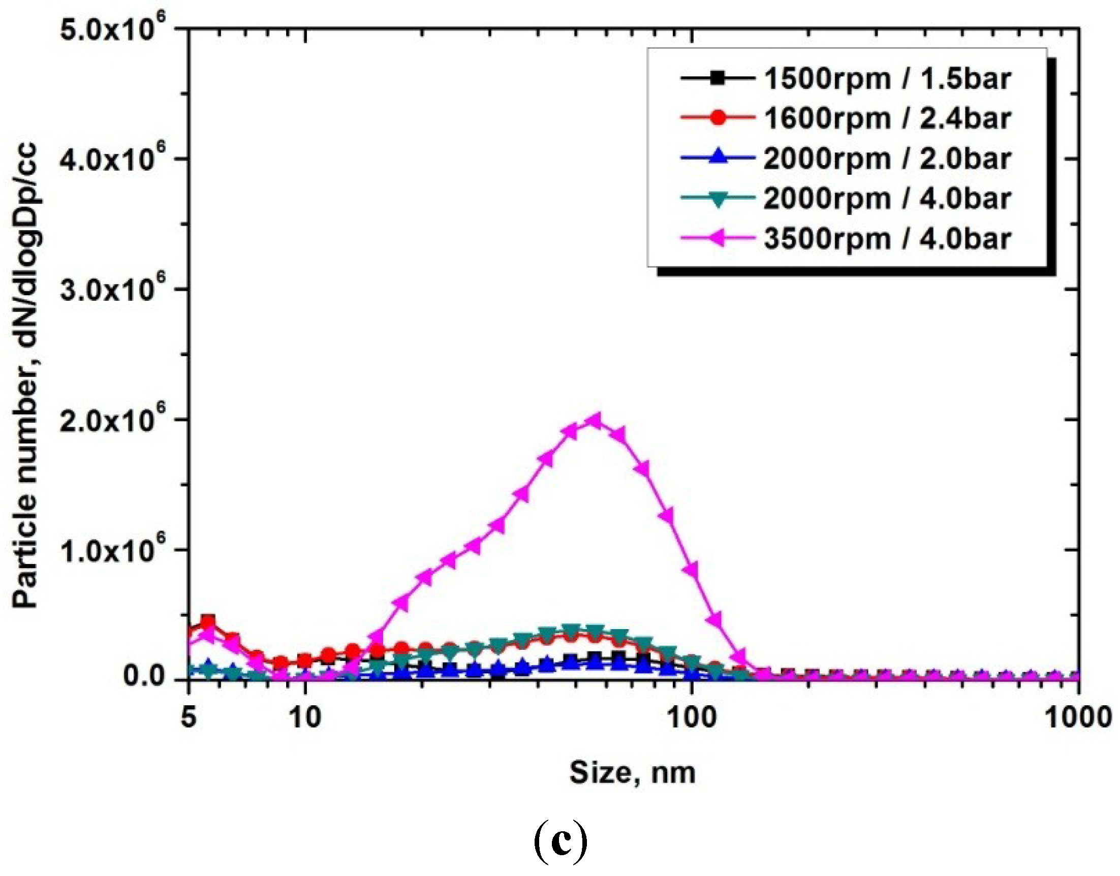
3.2. Particle Size Distribution and Part-Load Engine Operating Conditions

Figure 5 shows the particle size distributions of the GDI and GPF at three sampling positions. PM consists of tiny solid particles and liquid droplets ranging from a few nanometers to approximately one micrometer in diameter (below 1000 nm). Generally, PM size distributions are classified as tri-modal, and they primarily consist of nucleation, accumulation, and coarse modes. These modes are distinguished by the particle diameter [7,8,9,10].
Figure 5. Distributions of the particle size versus the number concentration in various part-load conditions; (a) engine out; (b) post-TWC; (c) post-GPF.
Energies 08 01865 g005aEnergies 08 01865 g005b
The particle size distribution at the engine-out sampling position was bi-modal with 10 nm < dp < 30 nm from 1500 rpm, BMEP 1.5 bars to 2000 rpm, BMEP 2.0 bars, and it consisted of accumulation mode particles with 40 nm < dp < 100 nm formed at 2000 rpm, BMEP 4.0 bars and 3500 rpm, BMEP 4.0 bars. In the case of the sampling position after the TWC, the distribution of nucleation mode particles was approximately 50% less than that of the engine-out position. Finally, the particle size distribution of the sampling position after the GPF had almost reduced values of both nucleation and accumulation mode particles, except under the 3500 rpm and BMEP 4.0 bars condition with higher exhaust flow rate and exhaust system temperature, as shown in Figure 3.

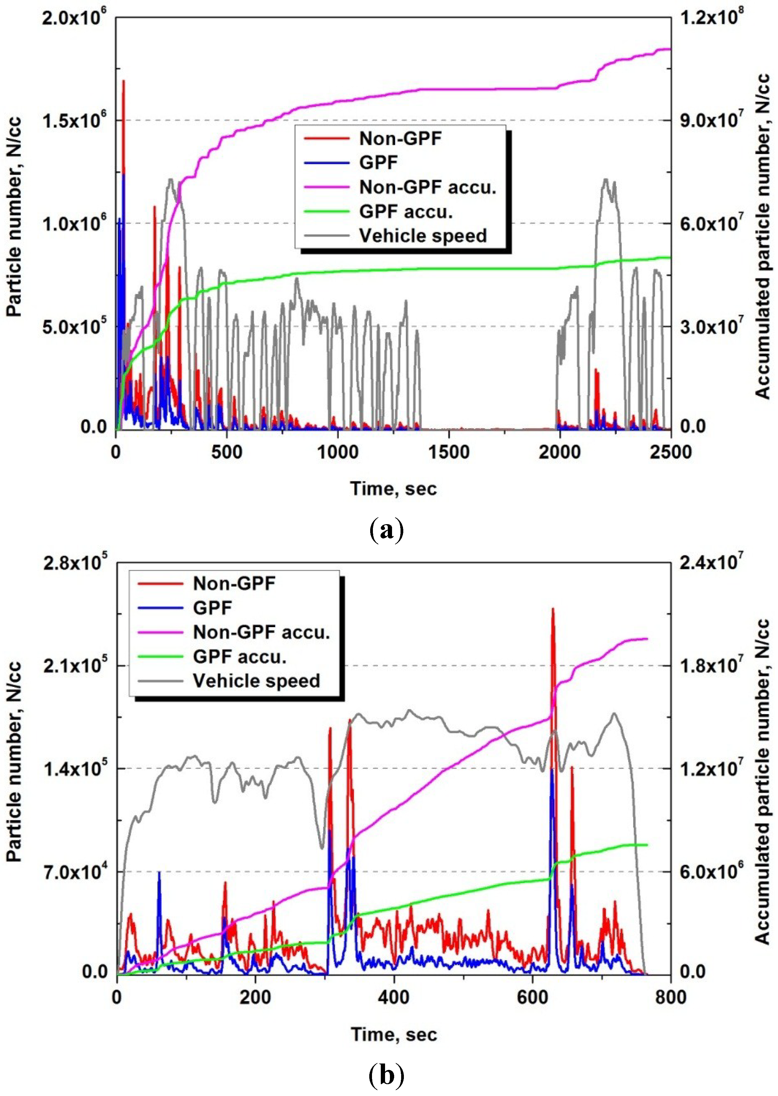
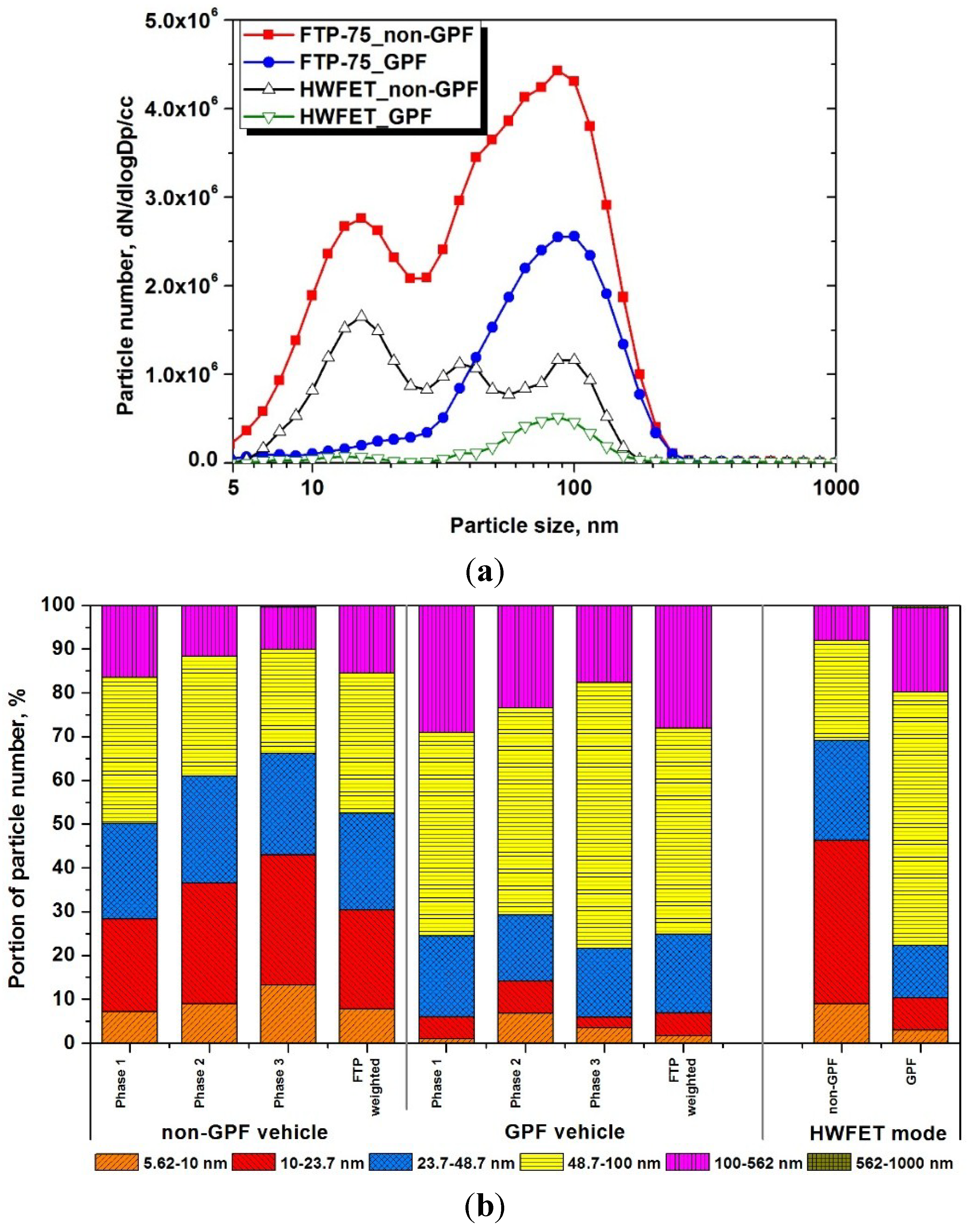
3.3. Particle Matter Emissions during Vehicle Driving Tests

The real-time PN concentration and the cumulative particle by CPC in the FTP-75 and HWFET mode are presented in Figure 6. In the system, volatile particles are removed through thermal treatment using a VPR, leaving particles that are operationally defined as solids over 23 nm particle sizes, to be counted by a CPC [29,30,32,39]. The levels of particle number emissions were closely related with the engine coolant temperature and the driving conditions of the vehicle. In the wall-guided GDI engine, the direct accumulation of injected fuel on a piston leads to rich combustion in the piston crown area, but an incomplete combustion results in soot formations [6,7,8,10,17,18,20,27,39,43]. Low vehicle speed and long idle times in phase 1 of the FTP-75 mode impact on late increment of the engine coolant, combustion chamber wall, and exhaust system temperatures. Low cylinder temperature during engine start and first tip-in of the FTP-75 mode produces more wall-films, which result in significant particle emissions. Optimization of engine control strategy of multiple injections combined with high injection pressure during cold start and cold transient operation stage is most effective measures for reducing PN emissions [8,9,10,11,15,16,17,18,27,31,43]. Moreover, installation of the GFP in GDI engines is a straightforward pathway for reducing both the nucleation mode and the accumulation mode particles [36,37,38,39]. After the GDI engine reached the fully warmed-up condition in phase 2 and phase 3 of the FTP-75 mode, the formation of nanoparticles remained at a very low level, except under acceleration conditions. Accumulated PN concentrations for the GDI and GPF-GDI engines indicated that most of the particles were formed within the first 250 s in the FTP-75 mode.
Figure 6. Real-time particle number concentration by CPC of FTP-75 and HWFET mode; (a) FTP-75 mode; (b) HWFET mode.
Energies 08 01865 g006
To examine the effect of vehicle speed on particle formation, the HWFET mode was also tested. The particle formation of the GDI vehicle increased sharply, compared to that of the GPF-GDI vehicle at steep acceleration points, although this mode included a hot engine start followed by fully warmed-up driving. The particle spikes of the base GDI vehicle during the aggressive acceleration points were due to the combination of the rich mixture formation and shifting of gears by the automatic transmission [18,21,24,30,31,33,34,35]. The PN emissions of the GPF-GDI vehicle through the HWFET mode were significantly lower than those of the base GDI vehicle. Especially, both the PN spikes during aggressive acceleration points and PN formation after 350 s of the HWFET mode with higher vehicle speed conditions were simultaneously mitigated by GPF installation.
Figure 7 shows the comparison of PN concentration levels of each phase of FTP-75 and HWFET mode with base GDI and GPF-equipped GDI vehicle. All the data of the particle concentration were tested about three times and averaged. The particle emissions were 2.89 × 10¹² N/km in phase 1 of the FTP-75 mode, and decreased to 4.36 × 10¹¹ and 3.86 × 10¹¹ N/km in the subsequent cycles, respectively, for the non-GPF case. The average FTP-75 weighted total particle emission was 9.32 × 10¹¹ N/km. The particle emissions for the GPF-equipped vehicles were 1.43 × 10¹² N/km for phase 1 of the FTP-75 mode, and they were 1.31 × 10¹¹ and 1.07 × 10¹¹ N/km in the subsequent cycles, respectively. The FTP-75 weighted total particle emission was 3.95 × 10¹¹ N/km, which was 57.6% less than that of the non-GPF case.
During the cold start and cold transient vehicle operating stages of low engine temperature conditions, the nanoparticles showed relatively low intensity Brownian motion; therefore, they had a low probability of colliding and adhering to the structure of the GPF [8,36,37,38,39,40,41,42]. Consequently, the filtration efficiency of the GPF remained at only 50.4% in phase 1 of the FTP-75 mode. However, the collection efficiencies of phase 2 and phase 3 of the FTP-75 mode increased to 69.8% and 72.2%, respectively. The PN emissions from the HWFET mode showed much lower concentration than from FTP-75 mode irrespective of with or without GPF installation mainly due to the fast fuel evaporation characteristics in the fully engine warm-up condition [17,21,26,33,34,39,43]. The total PN concentration of the GPF-GDI vehicle for the HWFET mode reduced at a rate of 61.6%.
Figure 7. Comparison of particle number emissions by CPC of each phase of FTP-75 and HWFET mode.
Energies 08 01865 g007

3.4. Particle Size Distribution and Part-Load Engine Operating Conditions

Figure 8 shows the particle size contribution and the portion of PN for the FTP-75 and HWFET modes obtained by the DMS500 installed at the tail pipe location to analyze the PN concentration and size distribution characteristics in the 5 nm to 1000 nm particle size ranges including below 23 nm.
Figure 8. Comparison of size-resolved particle concentration and portion of particle number by DMS500 in FTP-75 and HWFET mode; (a) particle number concentration and size distribution; (b) portion of size-resolved particle number concentration.
Energies 08 01865 g008
The particle size distribution for the GDI vehicle exhibit both nucleation and accumulation mode particles that are 10 nm < dp < 100 nm [5,6,8,9,10,16,17,18,20,26,33,34,35,43]. In contrast, the particle distribution for the GDI-GPF vehicle exhibit accumulation mode particles of 60 nm < dp < 100 nm, because the nucleation mode particles were removed in the GPF [38,39]. For the HWFET mode, which includes a high-speed and an acceleration gradient, the particle size distribution of the base GDI vehicle exhibits the three peaks of the sub-23 nm nucleation mode, 40 nm, and 100 nm particles. The particle below 50 nm was substantially reduced with GPF, and the size ranges of 80–90 nm particles were mainly emitted from the GPF equipped GDI vehicle.
As for the portion of PN, accumulation mode particles of diameters ranging 23–100 nm were primarily discharged during phase 1 of the FTP-75 mode for the GDI vehicle, when the engine and exhaust system were still in the cold condition. Only 28% of the total number of nanoparticles were sub-23 nm nucleation mode particles, and PM over 100 nm size composed 16% of the total particle number. In phase 2 and phase 3 of the FTP-75 mode, as the engine was fully warmed-up, the number of particles with diameters greater than 48 nm decreased to less than 40% of the total number of particles, and those of sub-23 nm particles increased to greater than 35%. Therefore, for the GDI engine, particles are assumed to be generated from the unburned hydrocarbons and the wall-film when the engine is in the cold condition, and these nanoparticles originating from hydrocarbons are relatively large [8,10,13,15,16,17,18,19,22,26,28,33,34,35,39,43]. In contrast, almost all of sub-23 nm nucleation particles were strongly reduced in the GDI-GPF vehicle, and its proportion relative to the total number of nanoparticles was not affected by the engine operating states. Sub-23 nm particles comprised only 6%, and particles larger than 48 nm accounted for 75% of the total number of particles for the GDI-GPF vehicle during phase 1, whereas that for the GDI was 49% over 48 nm particles. In phase 2 and phase 3, particles larger than 48 nm comprised more than 70% of the total fraction, and sub-23 nm particles comprised less than 14% of the total number of particles. Particle sizes for the GDI vehicle in the HWFET mode was mainly discharged 46% in sub-23 nm nucleation mode, whereas 77% of that by the GDI-GPF vehicle was mainly over 48 nm diameter particles.

3.5. Regulated Emissions, CO2, Fuel Economy and Particles

Table 4 summarizes the comparison of the regulated emissions (THC, CO, NOx, and PM), CO2 emissions, and the fuel economy (FE) of the GDI and GDI-GPF vehicles, respectively. The regulated emissions, CO2 emission, and the fuel economy of the GDI-GPF vehicle were similar to those of the GDI vehicle. Because the particles collected in the GPF occurred at the highest filtration efficiency, the PN and PM emissions were decreased by 57.6% and 64.0% for the FTP-75 mode, respectively. In the HWFET mode, the PN and the PM emissions level for the GPF vehicle were also lower than those for the FTP-75 weighted mode, and the filtration efficiency of the GPF for PN and PM emissions increased to 61.6% and 68.8%, respectively. Therefore, the metal foam-type GPF can reduce the particulate emissions to levels that satisfy the Euro-6 PN regulation for GDI vehicles without sacrificing engine performance or fuel economy.
Table 4. Regulated emissions, CO2, fuel economy, and particulates.
Driving modeTypeTHC (g/km)CO (g/km)NOx (g/km)CO2 (g/km)F.E. (km/L)PN (N/km)PM (mg/km)
FTP-75Non-GPF0.0100.2220.00420611.49.32 × 10111.262
GPF0.0110.2320.00520611.43.95 × 10110.454
HWFETNon-GPF0.0010.0530.00212319.02.31 × 10110.536
GPF0.0010.0670.00312418.98.86 × 10100.167

4. Conclusions

The PN concentrations, size distribution characteristics, and filtration efficiency of the metal foam-type GPF for the GDI engine in the part-load engine operating conditions and the vehicle test modes were investigated. The various exhaust system temperatures and pressure drop between the GPF which factors were closely connected with particle capturing efficiency and engine performance were also evaluated. The major findings obtained from this study are summarized as follows:
The TWC slightly removed the volatile hydrocarbon particle precursors by 22%–79% under low- and middle- engine speed and low- and middle-load conditions, while the TWC showed a small effect on particle emissions with a reduction of 11% under the high-engine speed, high-load conditions because of the higher exhaust flow rate. The filtration efficiency of the GPF was reached around 77%–96% in the low-to-medium part-load engine operating conditions. However, lower filtering efficiency of 53% was obtained at high speed condition by passive regeneration inside the GPF under high exhaust gas temperature above 650 °C. The size-resolved particle concentration from the GPF-GDI engine presented that both the nucleation and the accumulation mode particles were simultaneously reduced under steady-state part-load engine operating conditions.
Installation of the metal foam GPF in a GDI vehicle significantly impacted the particle concentration and the size-resolved PN emissions characteristics in the vehicle test modes. The PN emissions, mainly emitted during cold engine operation and high accelerating points in the GDI vehicle, were effectively reduced with adoption of the GPF. The average FTP-75 weighted total particle emission was 3.95 × 10¹¹ N/km from the GPF-GDI vehicle, which was 57.6% less than that of the non-GPF GDI vehicle. The size-resolved PN emissions from the metal foam GPF-GDI vehicle presented substantial PM filtering efficiency on the whole ranges of particles from the GDI vehicle. Sub-23 nm nucleation mode particle that was not counted in the Euro 6 PN regulation were of distinctive abatement features by 23%–36% of the total particles from the GPF-GDI vehicle.
The fuel economy, CO2, and regulated emissions with the GPF-GDI vehicle were equivalent to those of the base GDI vehicle under the vehicle certification modes of the FTP-75 and the HWFET. Adoption of the metal form type GPF for GDI vehicles has potential to meet the Euro 6 PN legislation with minimizing the penalties on the engine performance, exhaust gas emissions, and fuel efficiency in a GDI vehicle.

Acknowledgments

This study was supported by BK21 plus and by the Ministry of Trade, Industry and Energy of the Republic of Korea. We thank Alantum Company for their technical assistance for the metal foam-type GPF.

Author Contributions

All authors contributed to this work. Cha-Lee Myung and Juwon Kim performed a GDI engine and vehicle experiment for the evaluation of the advanced gasoline particulate filter (GPF), also wrote the major part of this article. Wonwook Jang and Dongyoung installed the GPF and analyzed the experimental data. Jeongmin Lee designed the metal-foam GPF and technical support. Professor Simsoo Park, the project manager, gave the academic advice for nano-particle characteristics from a GDI engine.

Conflicts of Interest

The authors declare no conflict of interest.

References

  1. Heywood, J.; Welling, O. Trends in performance characteristics of modern automobile SI and diesel engines. SAE Int. J. Engines 2009, 2, 1650–1662. [Google Scholar]
  2. Wu, X.S.; Daniel, R.; Tian, G.H.; Xu, H.M.; Huang, Z.H.; Richardson, D. Dual-injection: The flexible, bi-fuel concept for spark-ignition engines fuelled with various gasoline and biofuel blends. Appl. Energy 2011, 88, 2305–2314. [Google Scholar] [CrossRef]
  3. Johnson, T.V. Review of diesel emissions and control. Int. J. Engine Res. 2009, 10, 275–285. [Google Scholar] [CrossRef]
  4. Ristovski, Z.D.; Jayaratne, E.R.; Morawska, L.; Ayoko, G.A.; Lim, M. Particle and carbon dioxide emissions from passenger vehicles operating on unleaded petrol and LPG fuel. Sci. Total Environ. 2005, 345, 93–98. [Google Scholar] [CrossRef] [PubMed] [Green Version]
  5. Myung, C.L.; Park, S. Exhaust nanoparticle emissions from internal combustion engines: A review. Int. J. Automot. Technol. 2012, 13, 9–22. [Google Scholar] [CrossRef]
  6. Hwang, I.G.; Choi, K.; Kim, J.; Myung, C.L.; Park, S. Experimental evaluation of combustion phenomena in and nanoparticle emissions from a side-mounted direct-injection engine with gasoline and liquid-phase liquefied petroleum gas fuel. J. Automob. Eng. 2012, 226, 112–122. [Google Scholar] [CrossRef]
  7. Zhao, F.; Lai, M.C.; Harrington, D.L. Automotive spark-ignited direct-injection gasoline engines. Prog. Energy Combust. Sci. 1999, 25, 437–562. [Google Scholar] [CrossRef]
  8. Kittelson, D.B. Engines and nanoparticles: A review. J. Aerosol Sci. 1998, 29, 575–588. [Google Scholar] [CrossRef]
  9. Maricq, M.M.; Podsiadlik, D.H.; Chase, R.E. Gasoline vehicle particle size distributions: Comparison of steady state, FTP, and US06 measurements. Environ. Sci. Technol. 1999, 33, 2007–2015. [Google Scholar] [CrossRef]
  10. Myung, C.L.; Ko, A.; Park, S. Review on characterization of nano-particle emissions and PM morphology from internal combustion engines: Part 1. Int. J. Automot. Technol. 2014, 15, 203–218. [Google Scholar] [CrossRef]
  11. Gong, C.M.; Li, J.; Li, J.K.; Li, W.X.; Gao, Q.; Liu, X.J. Effects of ambient temperature on firing behavior and unregulated emissions of spark-ignition methanol and liquefied petroleum gas/methanol engines during cold start. Fuel 2011, 90, 19–25. [Google Scholar] [CrossRef]
  12. Costagliola, M.A.; De Simio, L.; Iannaccone, S.; Prati, M.V. Combustion efficiency and engine out emissions of a S.I. engine fueled with alcohol/gasoline blends. Appl. Energy 2013, 111, 1162–1171. [Google Scholar] [CrossRef]
  13. Broustail, G.; Halter, F.; Seers, P.; Moreac, G.; Mounaim-Rousselle, C. Comparison of regulated and non-regulated pollutants with iso-octane/butanol and iso-octane/ethanol blends in a port-fuel injection spark-ignition engine. Fuel 2012, 94, 251–261. [Google Scholar] [CrossRef]
  14. Lee, J.; Choi, S.; Kim, H.; Kim, D.; Choi, H.; Min, K. Reduction of emissions with propane addition to a diesel engine. Int. J. Automot. Technol. 2013, 14, 551–558. [Google Scholar] [CrossRef]
  15. Bielaczyc, P.; Szczotka, A.; Woodburn, J. The effect of a low ambient temperature on the cold-start emissions and fuel consumption of passenger cars. J. Automob. Eng. 2011, 225, 1253–1264. [Google Scholar] [CrossRef]
  16. Myung, C.L.; Kim, J.; Choi, K.; Hwang, I.G.; Park, S. Comparative study of engine control strategies for particulate emissions from direct injection light-duty vehicle fueled with gasoline and liquid phase liquefied petroleum gas (LPG). Fuel 2012, 94, 348–355. [Google Scholar] [CrossRef]
  17. Park, C.W.; Oh, H.C.; Kim, S.D.; Kim, H.S.; Lee, S.Y.; Bae, C.S. Evaluation and visualization of stratified ultra-lean combustion characteristics in a spray-guided type gasoline direct-injection engine. Int. J. Automot. Technol. 2014, 15, 525–533. [Google Scholar] [CrossRef]
  18. Peckham, M.S.; Finch, A.; Campbell, B.; Price, P.; Davies, M.T. Study of Particle Number Emissions from a Turbocharged Gasoline Direct Injection (GDI) Engine Including Data from A Fast-Response Particle Size Spectrometer; SAE Technical Paper; Society of Automotive Engineers: Warrendale, PA, USA, 2011. [Google Scholar]
  19. Arsie, I.; Di Iorio, S.; Vaccaro, S. Experimental investigation of the effects of AFR, spark advance and EGR on nanoparticle emissions in a PFI SI engine. J. Aerosol Sci. 2013, 64, 1–10. [Google Scholar] [CrossRef]
  20. Bonatesta, F.; Chiappetta, E.; La Rocca, A. Part-load particulate matter from a GDI engine and the connection with combustion characteristics. Appl. Energy 2014, 124, 366–376. [Google Scholar] [CrossRef]
  21. Karavalakis, G.; Durbin, T.D.; Shrivastava, M.; Zheng, Z.Q.; Villela, M.; Jung, H.J. Impacts of ethanol fuel level on emissions of regulated and unregulated pollutants from a fleet of gasoline light-duty vehicles. Fuel 2012, 93, 549–558. [Google Scholar] [CrossRef]
  22. Ristimaki, J.; Keskinen, J.; Virtanen, A.; Maricq, M.; Aakko, P. Cold temperature PM emissions measurement: Method evaluation and application to light duty vehicles. Environ. Sci. Technol. 2005, 39, 9424–9430. [Google Scholar] [CrossRef] [PubMed]
  23. Fang, S.C.; Cassidy, A.; Christiani, D.C. A systematic review of occupational exposure to particulate matter and cardiovascular disease. Int. J. Environ. Res. Public. Health 2010, 7, 1773–1806. [Google Scholar] [CrossRef] [PubMed]
  24. Myung, C.L.; Ko, A.; Lim, Y.; Kim, S.; Lee, J.; Choi, K.; Park, S. Mobile source air toxic emissions from direct injection spark ignition gasoline and lpg passenger car under various in-use vehicle driving modes in korea. Fuel Process. Technol. 2014, 119, 19–31. [Google Scholar] [CrossRef]
  25. Choi, S.; Myung, C.L.; Park, S. Review on characterization of nano-particle emissions and PM morphology from internal combustion engines: Part 2. Int. J. Automot. Technol. 2014, 15, 219–227. [Google Scholar] [CrossRef]
  26. Seong, H.; Choi, S.; Lee, K. Examination of nanoparticles from gasoline direct-injection (GDI) engines using transmission electron microscopy (TEM). Int. J. Automot. Technol. 2014, 15, 175–181. [Google Scholar] [CrossRef]
  27. Gaddam, C.K.; Vander Wal, R.L. Physical and chemical characterization of SIDI engine particulates. Combust. Flame 2013, 160, 2517–2528. [Google Scholar] [CrossRef]
  28. Commodo, M.; Sgro, L.A.; Minutolo, P.; D’Anna, A. Characterization of combustion-generated carbonaceous nanoparticles by size-dependent ultraviolet laser photoionization. J. Phys. Chem. A 2013, 117, 3980–3989. [Google Scholar] [CrossRef] [PubMed]
  29. Giechaskiel, B.; Maricq, M.; Ntziachristos, L.; Dardiotis, C.; Wang, X.L.; Axmann, H.; Bergmann, A.; Schindler, W. Review of motor vehicle particulate emissions sampling and measurement: From smoke and filter mass to particle number. J. Aerosol Sci. 2014, 67, 48–86. [Google Scholar] [CrossRef]
  30. Giechaskiel, B.; Mamakos, A.; Andersson, J.; Dilara, P.; Martini, G.; Schindler, W.; Bergmann, A. Measurement of automotive nonvolatile particle number emissions within the european legislative framework: A review. Aerosol Sci. Technol. 2012, 46, 719–749. [Google Scholar] [CrossRef]
  31. Fontaras, G.; Franco, V.; Dilara, P.; Martini, G.; Manfredi, U. Development and review of Euro 5 passenger car emission factors based on experimental results over various driving cycles. Sci. Total Environ. 2014, 468, 1034–1042. [Google Scholar] [CrossRef] [PubMed]
  32. Chung, M.C.; Kim, M.S.; Sung, G.S.; Kim, S.M.; Lee, J.W. Comparison study on characteristics of nano-sized particle number distribution by using condensation particle counter calibrated with spray and soot type particle generation methods. Int. J. Automot. Technol. 2014, 15, 877–884. [Google Scholar] [CrossRef]
  33. Whelan, I.; Samuel, S.; Hassaneen, A. Investigation into the Role of Catalytic Converters on Tailpipe-Out Nano-Scale Particulate Matter from Gasoline Direct Injection Engine; SAE Technical Paper; Society of Automotive Engineers: Warrendale, PA, USA, 2010. [Google Scholar]
  34. Samuel, S.; Hassaneen, A.; Morrey, D. Particulate Matter Emissions and the Role of Catalytic Converter during Cold Start of GDI Engine; SAE Technical Paper; Society of Automotive Engineers: Warrendale, PA, USA, 2010. [Google Scholar]
  35. Whelan, I.; Timoney, D.; Smith, W.; Samuel, S. The Effect of a Three-Way Catalytic Converter on Particulate Matter from a Gasoline Direct-Injection Engine during Cold-Start; SAE Technical Paper; Society of Automotive Engineers: Warrendale, PA, USA, 2013. [Google Scholar]
  36. Swanson, J.J.; Watts, W.F.; Newman, R.A.; Ziebarth, R.R.; Kittelson, D.B. Simultaneous reduction of particulate matter and NOx emissions using 4-way catalyzed filtration systems. Environ. Sci. Technol. 2013, 47, 4521–4527. [Google Scholar] [CrossRef] [PubMed]
  37. Opitz, B.; Drochner, A.; Vogel, H.; Votsmeier, M. An experimental and simulation study on the cold start behaviour of particulate filters with wall integrated three way catalyst. Appl. Catal. B Environ. 2014, 144, 203–215. [Google Scholar] [CrossRef]
  38. Vogt, C.D.; Kattouah, P.; Kato, K.; Thier, D.; Ohara, E.; Ito, Y.; Shimada, T.; Shibagaki, Y.; Yuuki, K.; Sakamoto, H. Novel GPF concepts with integrated catalyst for low backpressure and low CO2 emissions. In Proceedings of the 23rd Aachen Colloquium Automobile and Engine Technology, Eurogress Aachen, Germany, 6–8 Octoboer 2014.
  39. Choi, K.; Kim, J.; Ko, A.; Myung, C.L.; Park, S.; Lee, J. Size-resolved engine exhaust aerosol characteristics in a metal foam particulate filter for GDI light-duty vehicle. J. Aerosol Sci. 2013, 57, 1–13. [Google Scholar] [CrossRef]
  40. Tsuneyoshi, K.; Takagi, O.; Yamamoto, K. Effects of Washcoat on Initial PM Filtration Efficiency and Pressure Drop in SiC DPF; SAE Technical Paper; Society of Automotive Engineers: Warrendale, PA, USA, 2011. [Google Scholar]
  41. Yamamoto, K.; Matsui, K. Diesel Exhaust after-treatment by silicon carbide fiber filter. Fibers 2014, 2, 128–141. [Google Scholar] [CrossRef]
  42. Maik, B.; Kirchner, U.; Vogt, R.; Benter, T. On-road and laboratory investigation of low-level PM emissions of a modern diesel particulate filter equipped diesel passenger car. Atmos. Environ. 2009, 43, 1908–1916. [Google Scholar] [CrossRef]
  43. Choi, K.; Kim, J.; Myung, C.L.; Lee, M.; Kwon, S.; Lee, Y.; Park, S. Effect of the mixture preparation on the nanoparticle characteristics of gasoline direct-injection vehicles. J. Automob. Eng. 2012, 226, 1514–1524. [Google Scholar] [CrossRef]

