
Reliability Analysis Models for Differential Protection Considering Communication Delays and Errors

Abstract
:1. Introduction
2. Definitions
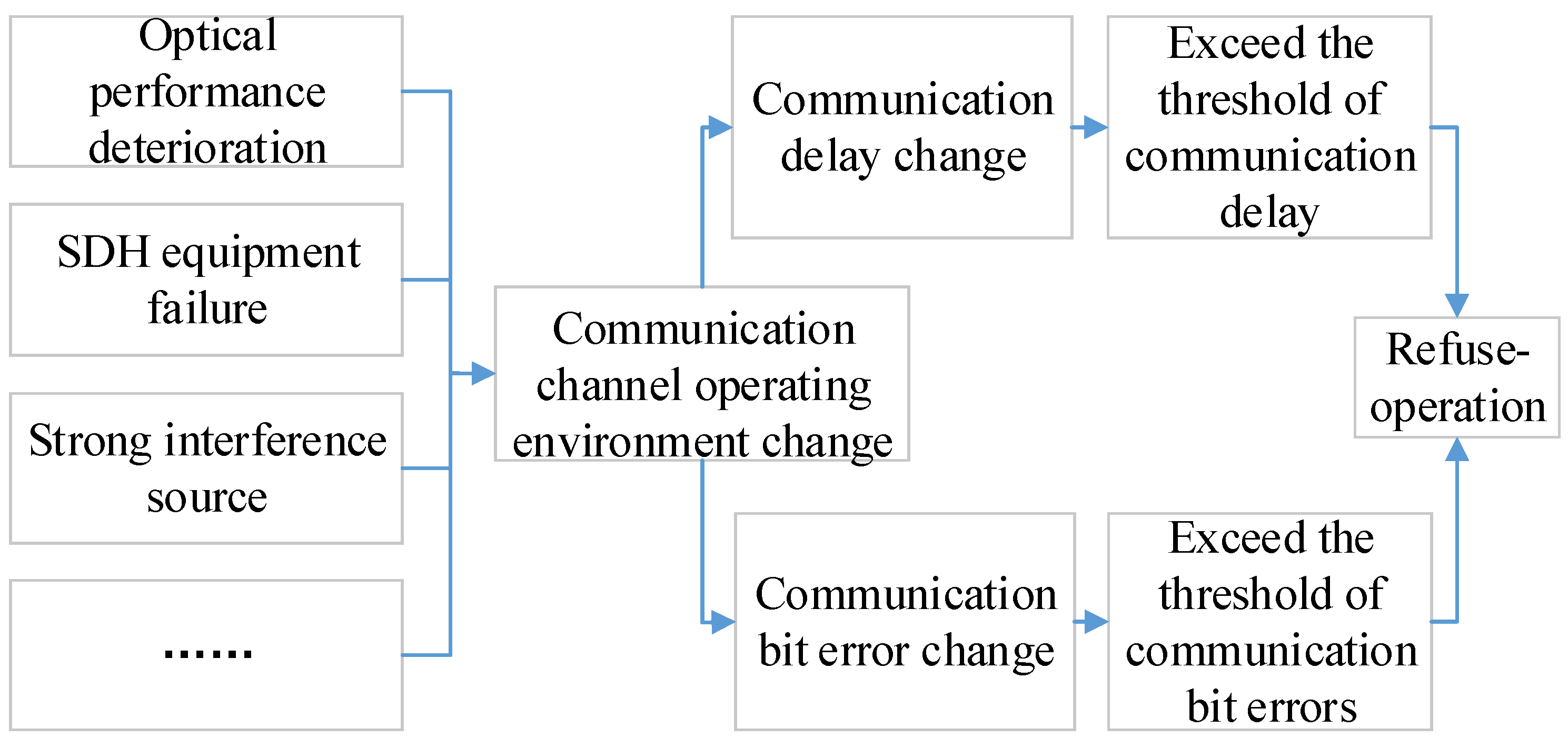
- Refuse-operation: A communication delay or bit error causes the relay protection to lock, and as a result, the relay protection doesn’t start when a given fault occurs within the protection range.
- False trip: A communication delay or bit error causes the relay protection device activation when no fault has occured within the protection range.

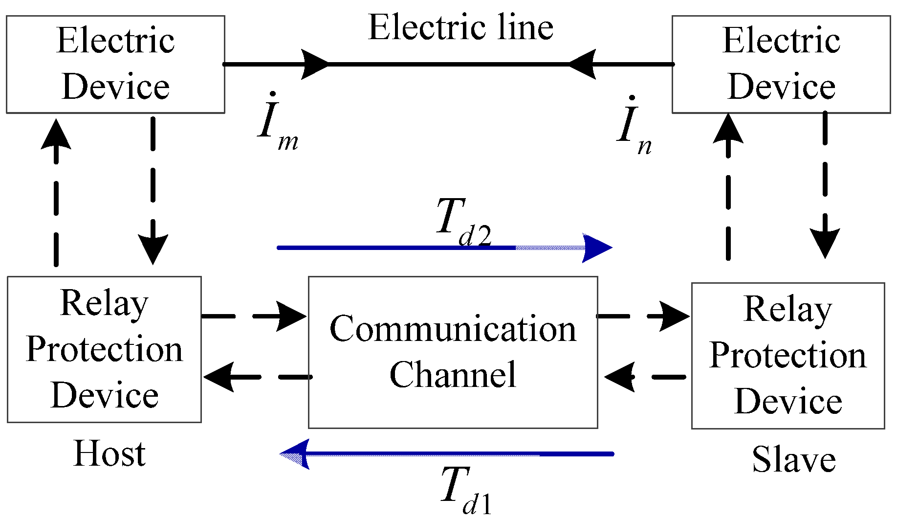
3. Malfunction Probability Models for Communication Delays and Bit Errors
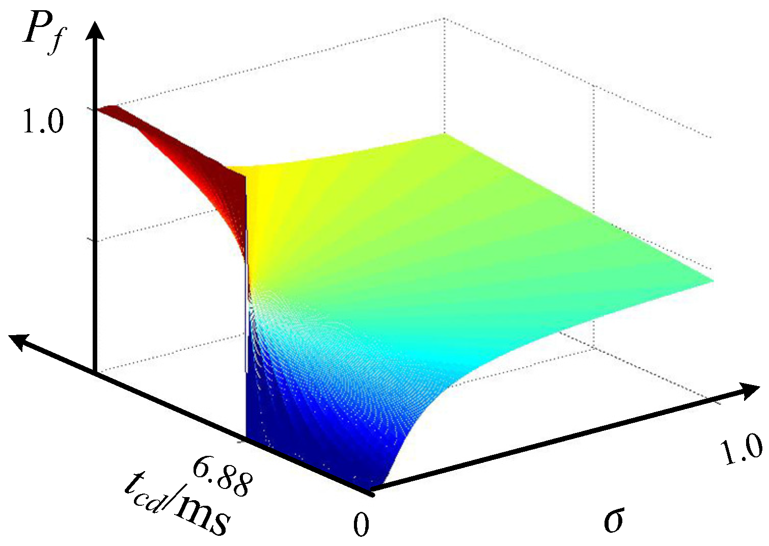
3.1. False Trip Probability Model for Inconsistent Delays
3.1.1. Relationship between Inconsistent Delay and Protection Action Criterion
- (1)
- The action criterion of the current differential protectionCurrently, the following two criteria are commonly used for the activation of transmission line phase current differential protection [5,22]:Start criterion: Icd ≥ Iop, Icd is the differential current; Iop is a constant determined offline. The threshold of the relay protection is Imax:Braking ratio criterion: Icd ≥ kIres; k is the braking coefficient; Ires is the amount of braking current. Two typical forms of Ires are:
- (a)
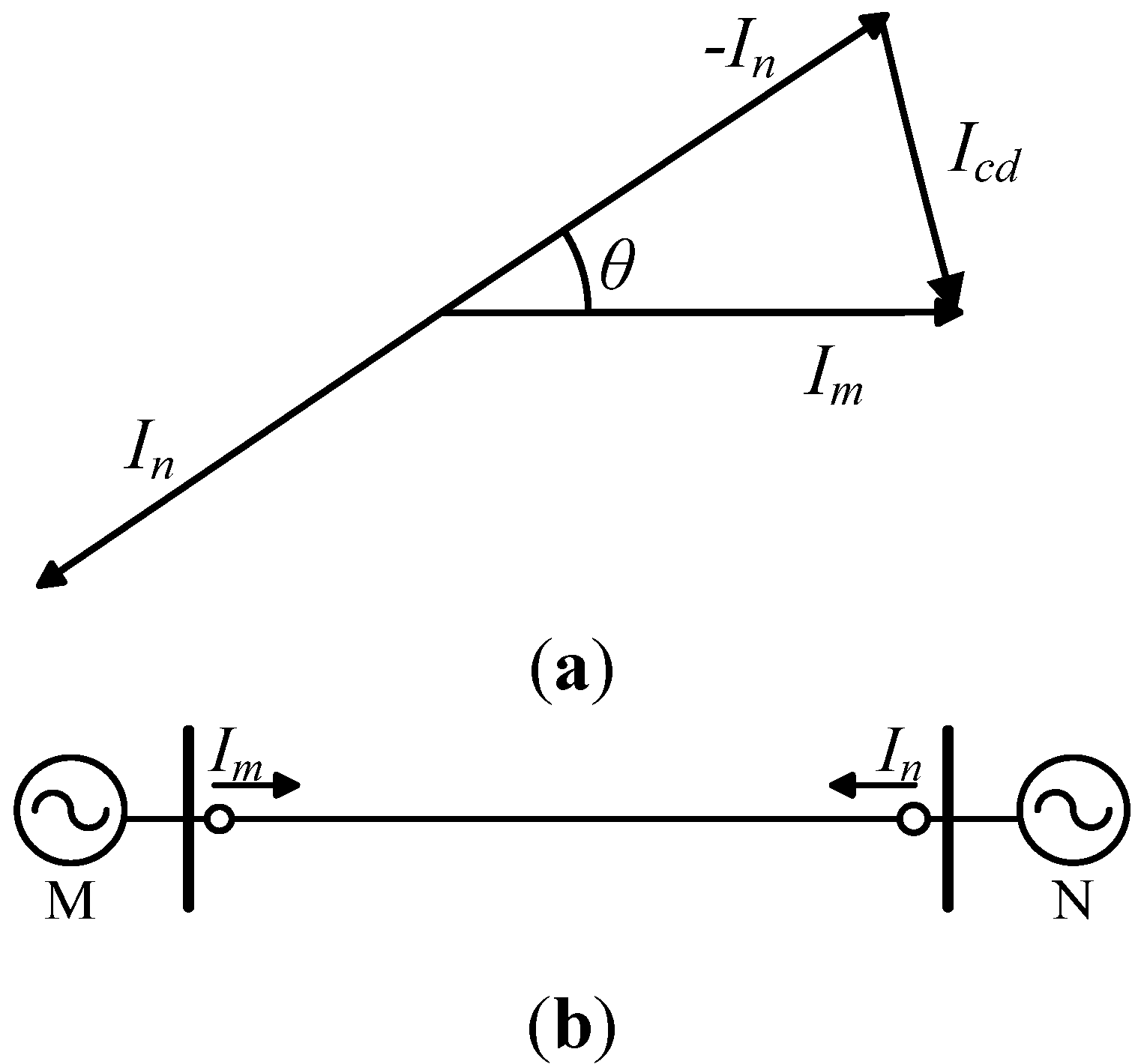
- . The relationship between the currents of two ends and measured current is depicted in Figure 2. According to the braking ratio criterion, the threshold for this criterion can be expressed as:where IL is load current, ω is synchronous angular velocity.
- (b)
- . The threshold of the relay protection using this criterion is:
- (2)
- The relationship between the differential current and inconsistent delayThe inconsistent delay tcd causes the sampling time error (tcd/2) between the two ends [23]. This produces a differential current Icd when there no fault is happening or the fault is out of protection area. From Figure 2a, the angle difference between −In and Im can be obtained:θ = tcd × ω/2Therefore, the differential current is:Equation (7) shows the relationship between the differential current and the inconsistent delay.

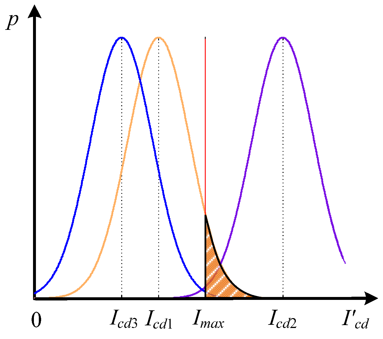
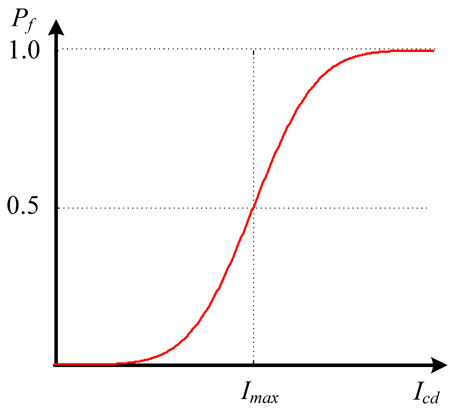
3.1.2. False Trip Probability for Inconsistent Delays


- If , then the probability can be expressed as:
- If , then the probability can be expressed as:

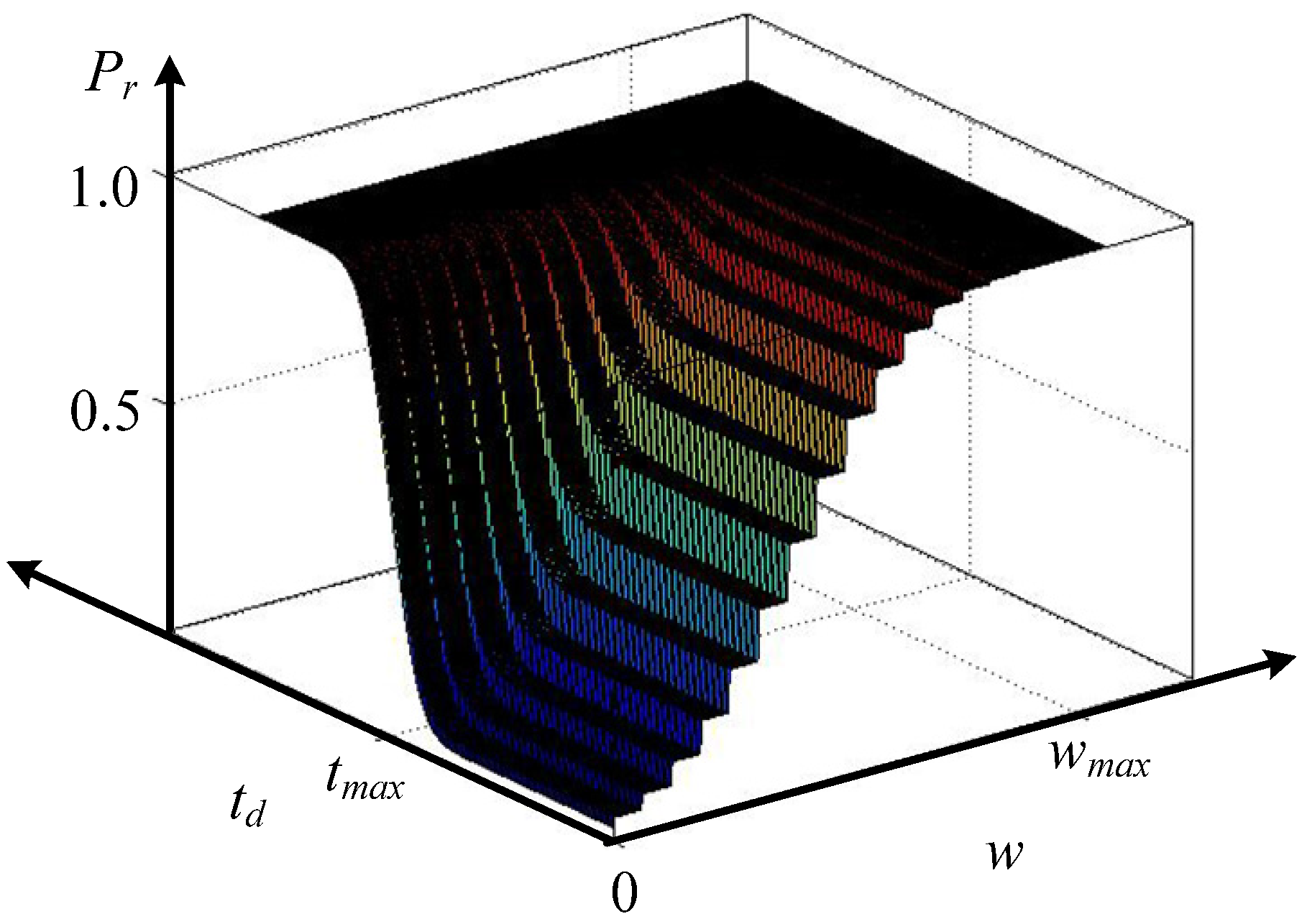
3.2. Refuse-Operation Probability Model for Consistent Delays


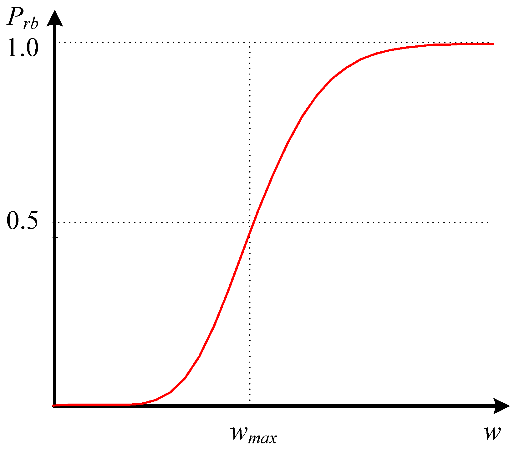
3.3. Refuse-Operation Probability Model for Bit Errors


3.4. Refuse-Operation Probability Model for Consistent Delays and Bit Errors


4. Simulations

| Parameters | Name | Value | Description |
|---|---|---|---|
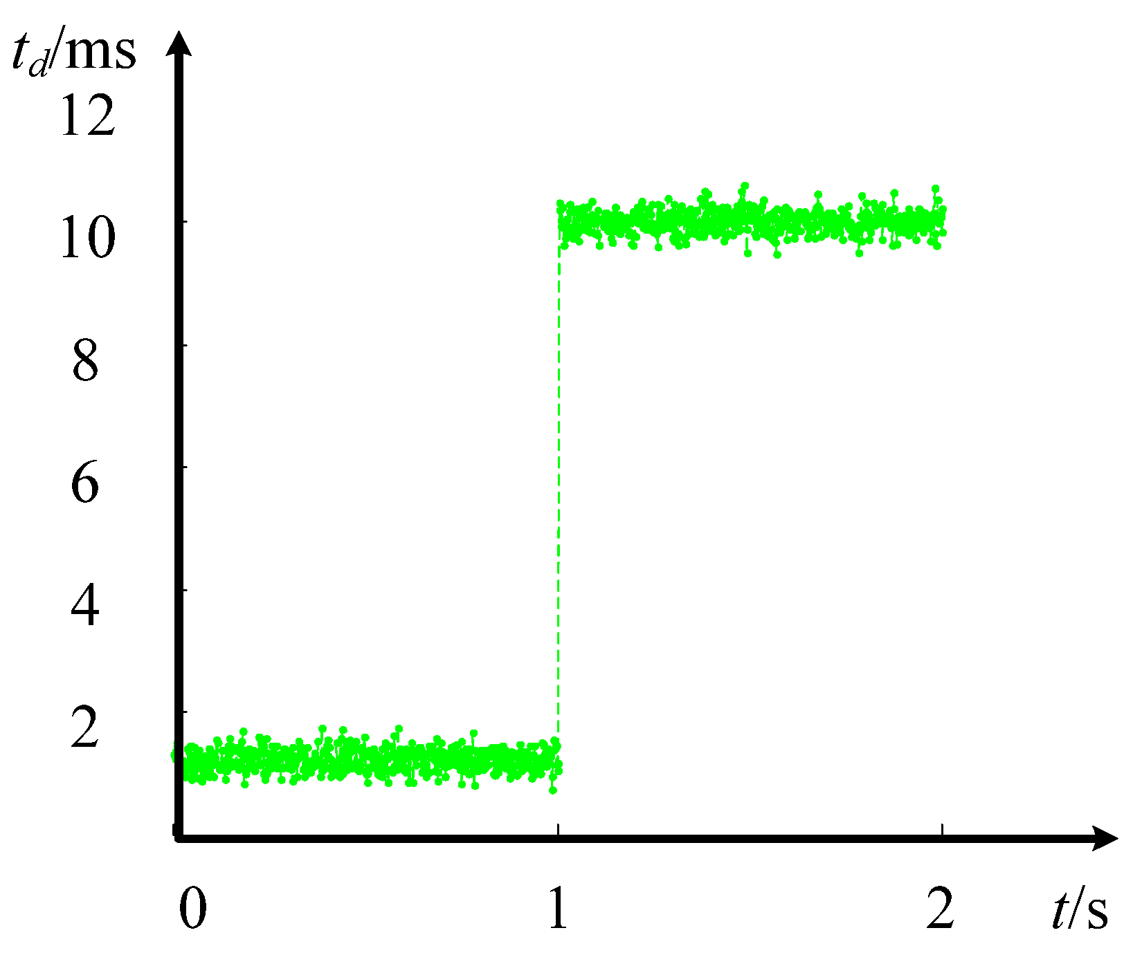
| tmax | Consistent delay threshold | 12 ms | If the measured consistent delay t is larger than tmax, the relay will refuse to operate when internal fault occurs. |
| σ1 | Normal distribution standard deviation of consistent delay | 1/6 ms | (1) Considering the uncertainty of environment impacts and communication condition variations, the consistent delay t follows the Normal distribution. |
| (2) Assuming 99.7% of consistent delay is less than 1 ms, then according to the probability theory the consistent delay fluctuation standard deviation is 1/6 ms. | |||
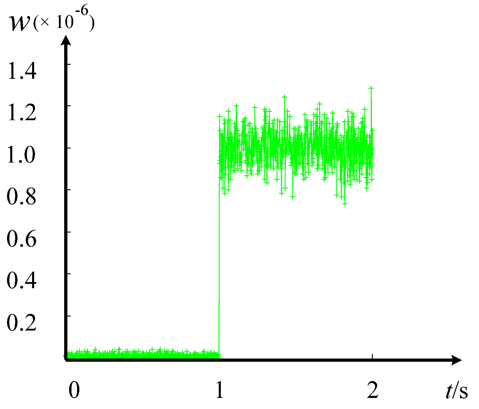
| wmax | Communication bit error rate threshold | 2 × 10⁻⁶ | (1) If the measured bit error rate w is larger than the wmax, the relay will refuse to operate when internal fault occurs. |
| (2) The value of communication bit error rate threshold is relative fuzzy, it may be related to the types of relay protection and the distribution of the communication bit error. Here we select a typical value 2 × 10⁻⁶. | |||
| Iop | Current start threshold for start criterion | 0.5 × IN | Protection operates when the differential current is larger than Iop. |
| σ | Normal distribution standard deviation of differential current caused by inconsistent delay | 0.26 × IN | The selected value 0.26 × IN is calculated from the reliable coefficient of current different protection. |
| k | Braking coefficient | 0.6 | Braking coefficient in braking ratio criterion. |
4.1. Key Factors Affecting the Malfunction Probability


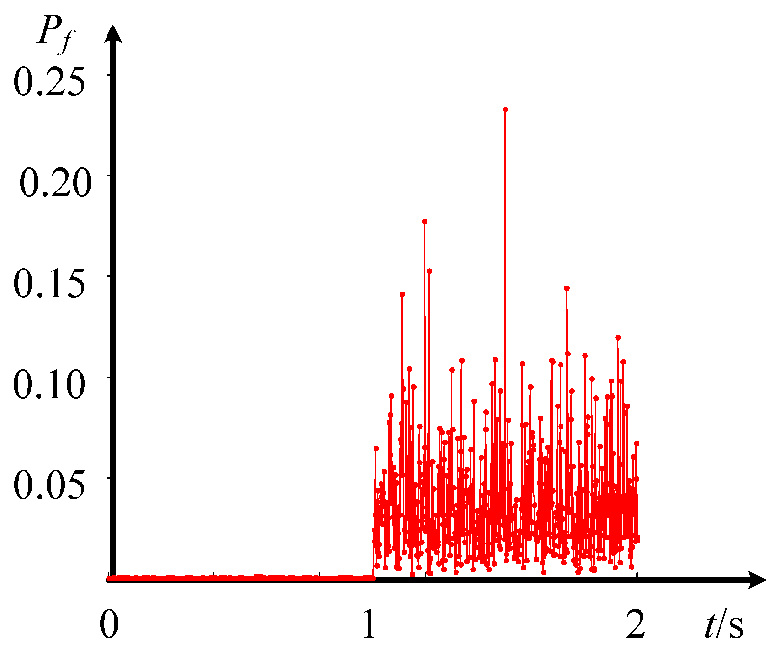
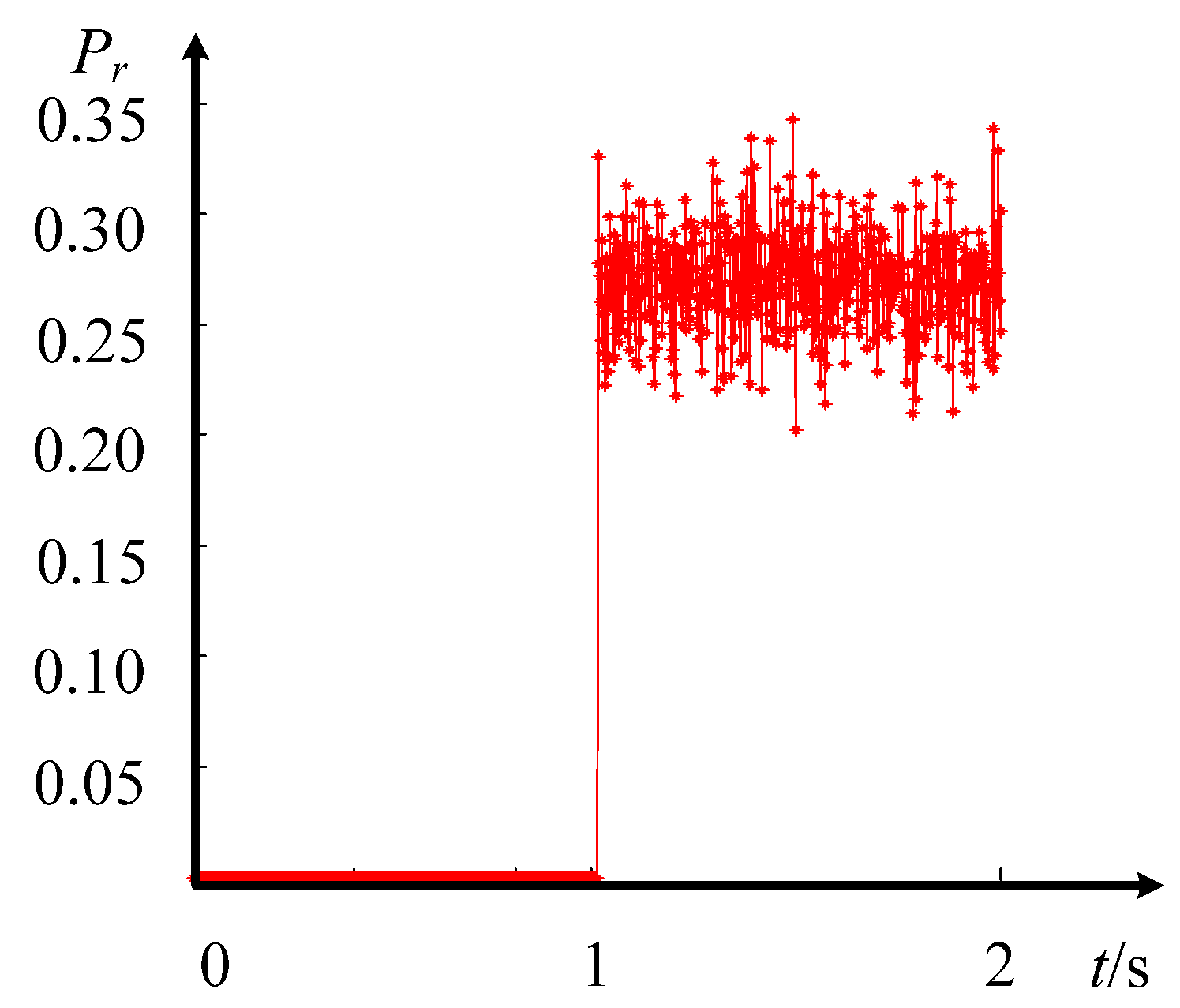
4.2. Comparison of Mal-Function Probabilities in Normal and Abnormal Communication Conditions


5 Conclusions
Acknowledgments
Author Contributions
Conflicts of Interest
References
- Dambhare, S.; Soman, S.A.; Chandorkar, M.C. Current differential protection of transmission line using the moving window averaging technique. IEEE Trans. Power Deliv. 2009, 25, 610–620. [Google Scholar] [CrossRef]
- Wen, M.; Chen, D.; Yin, X. Instantaneous value and equal transfer processes-based current differential protection for long transmission lines. IEEE Trans. Power Deliv. 2011, 27, 289–299. [Google Scholar] [CrossRef]
- Li, B.; Li, C.; He, J.; Yip, T. Novel principle and adaptive scheme of phase correlation line current differential protection. Int. Trans. Electr. Energy Syst. 2013, 23, 733–750. [Google Scholar] [CrossRef]
- Solak, K.; Rebizant, W.; Klimek, A. Fuzzy adaptive transmission-line differential relay immune to CT saturation. IEEE Trans. Power Deliv. 2012, 27, 766–772. [Google Scholar] [CrossRef]
- Dambhare, S.; Soman, S.; Chandorkar, M. Adaptive current differential protection schemes for transmission-line protection. IEEE Trans. Power Deliv. 2009, 24, 1832–1841. [Google Scholar] [CrossRef]
- Yin, S.; Ding, S.X.; Xie, X.; Luo, H. A review on basic data-driven approaches for industrial process monitoring. IEEE Trans. Ind. Electr. 2014, 61, 6418–6428. [Google Scholar] [CrossRef]
- Yin, S.; Li, X.; Gao, H.; Kaynak, O. Data-based techniques focused on modern industry: An overview. IEEE Trans. Ind. Electr. 2015, 62, 657–667. [Google Scholar] [CrossRef]
- Yin, S.; Zhu, X.; Kaynak, O. Improved PLS focused on key performance indictor related fault diagnosis. IEEE Trans. Ind. Electr. 2015, 62, 1651–1658. [Google Scholar] [CrossRef]
- Yin, S.; Huang, Z. Performance monitoring for vehicle suspension system via fuzzy positivistic C-means clustering based on accelerometer measurements. IEEE/ASME Trans. Mechatron. 2014, PP, 1–8. [Google Scholar] [CrossRef]
- Hodder, S.; Kasztenny, B.; Fischer, N. Backup considerations for line current differential protection. In Proceedings of the 2012 65th Annual Conference for Protective Relay Engineers, College Station, TX, USA, 2–5 April 2012; pp. 96–107.
- Li, H.Y.; Southern, E.P.; Crossley, P.A.; Potts, S. A new type of differential feeder protection relay using the Global Positioning System for data synchronization. IEEE Trans. Power Deliv. 2002, 12, 1090–1099. [Google Scholar] [CrossRef]
- Zhang, M.; Dong, X.; Bo, Z.Q.; Caunce, B.R.J. A new current differential protection scheme for two-terminal transmission lines. In Proceedings of the IEEE Power Engineering Society General Meeting, Tampa, FL, USA, 24–28 June 2007; pp. 1–6.
- Gao, H.; Chen, T.; Lam, J. A new delay system approach to network-based control. Automatica 2008, 44, 39–52. [Google Scholar] [CrossRef]
- Ward, S.; Higinbotham, W. Network errors and their influence on current differential relaying. In Proceedings of the 2011 64th Annual Conference for Protective Relay Engineers, College Station, TX, USA, 11–14 April 2011; pp. 79–90.
- Kwong, W.S.; Clayton, M.J.; Newbould, A. A microprocessor-based current differential relay for use with digital communication systems. IEE Conf. Publ. 1985, 249, 65–69. [Google Scholar]
- Hirschler, B. Practical application of 1588 security. In Proceedings of the 2008 IEEE International Symposium on Precision Clock Synchronization for Measurement, Control and Communication, Ann Arbor, MI, USA, 22–26 September 2008; pp. 37–43.
- Eidson, J.C.; Fischer, M.; White, J. IEEE-1588 Standard for a precision clock synchronization protocol for networked measurement and control systems. In Proceedings of the 34th Annual PTTI Meeting, Reston, VA, USA, 3–5 December 2002; pp. 243–254.
- Eidson, J.C. IEEE-1588 Standard Version 2. Agilent Laboratories, Measurement Research Lab: Palo Alto, CA, USA, 5 March 2007. [Google Scholar]
- Kasztenny, B.; Fischer, N.; Fodero, K.; Zvarych, A. Communications and data synchronization for line current differential schemes. In Proceedings of the 38th Annual Western Protective Relay Conference, Spokane, WA, USA, 18 October 2011; pp. 1–19.
- Gartia, A.; Gartia, A.; Gulati, A.; Kumar, C. Microcontroller based line differential protection using fiber optic communication. In Proceedings of the 2003 IEEE Innovative Smart Grid Technologies-Asia (ISGT Asia), Bangalore, India, 10–13 November 2013; pp. 1–4.
- Kowalik, R.; Januszewski, M.; Rasolomampionona, D. Problems found during testing synchronous digital hierarchical devices used on power protection systems. IEEE Trans. Power Deliv. 2013, 28, 11–20. [Google Scholar] [CrossRef]
- Miller, H.; Burger, J.; Fischer, N.; Kasztenny, B. Modern line current differential protection solutions. In Proceedings of the 2010 63rd Annual Conference for Protective Relay Engineers, College Station, TX, USA, 29 March–1 April 2010; pp. 1–25.
- Fukushima, S.; Yamada, J.; Mori, T.; Kawano, F. Development of line current differential relay over native ethernet. In Proceedings of the 12th IET International Conference on Developments in Power System Protection (DPSP 2014), Copenhagen, Denmark, 31 March–3 April 2014; pp. 1–5.
- Gao, H.S.; Ma, B.Y. A longitudinal differential protection channel delay model based on the probability distribution. Power Syst. Protect. Control 2014, 17, 61–65. [Google Scholar]
- Ouyang, L.J.; Xu, Q.Q.; Xu, Q.S.; Wang, X. Experiment analysis and research of the effect of channel inconsistent delay on the differential criterion. Power Syst. Protect. Control 2011, 8, 80–85. [Google Scholar]
- Xu, Q.Q.; Zhang, Y.G.; Zhou, D.J.; Zhu, J.H.; Li, S. Experimentation and research of optical fiber channel to the line differential protection PSL603U. Power Syst. Protect. Control 2010, 11, 75–80. [Google Scholar]
- Qin, W.P.; Hao, Y.J.; Liu, Y.M. Influence of communication channel time delay on microcomputer-based relay protection. Power Syst. Protect. Control 2009, 7, 58–62. [Google Scholar]
- Sheng, S.; Li, K.K.; Chan, W.L.; Zeng, X.J. Adaptive agent-based wide-area current differential protection system. IEEE Trans. Ind. Appl. 2010, 46, 2111–2117. [Google Scholar] [CrossRef]
© 2015 by the authors; licensee MDPI, Basel, Switzerland. This article is an open access article distributed under the terms and conditions of the Creative Commons Attribution license (http://creativecommons.org/licenses/by/4.0/).
Share and Cite
Wu, Y.; Li, M.; Tang, Y.; Fu, R.; Ni, M. Reliability Analysis Models for Differential Protection Considering Communication Delays and Errors. Energies 2015, 8, 2454-2472. https://doi.org/10.3390/en8042454
Wu Y, Li M, Tang Y, Fu R, Ni M. Reliability Analysis Models for Differential Protection Considering Communication Delays and Errors. Energies. 2015; 8(4):2454-2472. https://doi.org/10.3390/en8042454
Chicago/Turabian StyleWu, Yingjun, Manli Li, Yi Tang, Rong Fu, and Ming Ni. 2015. "Reliability Analysis Models for Differential Protection Considering Communication Delays and Errors" Energies 8, no. 4: 2454-2472. https://doi.org/10.3390/en8042454