1. Introduction: The Application of Volumetric Expanders in ORC Systems
Effective energy recovery from renewable and waste energy sources is one of the most important present-day problems [
1]. Advanced energy systems based on local waste heat, renewables and fossil fuel resources can provide opportunity for an increase of consumers’ energy safety and energy supply continuity [
2]. They can also provide the chance for development of prosumers [
3], which are the energy consumers able to produce energy for their own needs. However, implementation of local and prosumer energy systems requires access to the relevant energy conversion technologies.
One of the most promising energy conversion technologies is the ORC system [
4]. The Organic Rankine cycle has the same configuration as the well-known classical steam Rankine cycle but uses low-boiling working media instead of water. ORC power systems may differ in power, purpose and technical configuration. Micro power (0.5–10 kW), small power (10–100 kW), medium power (100–500 kW) and large power (500 kW and more) systems are available. They can operate as [
5] power plants, CHP’s and multi-generation systems.
The most important problems connected with ORC system design are the selection of a suitable working fluid and expander. Currently there is a wide range of applicable working fluids available [
6] and many appropriate selection methods [
7]. Expander selection is mainly based on the system power and its purpose. In general two types of expanders can be applied in ORC systems: one are turbines, the other is volumetric machines.
Turbines are mainly applied in large and medium power ORC systems powered by heat sources with high thermal capacity (1 MW and more) and temperature (150 °C and more), such as large industrial waste sources [
8] e.g., steam boilers or gas turbine exhaust gases. In the large power systems silicone oils (e.g., hexamethyldisiloxane (MM) or octamethyltrisiloxane (MDM)) are mainly adopted as working fluids [
9]. Since large power ORC’s are now well developed, most research works focus on the optimization of the design [
10].
Volumetric expanders are applied mainly in micro and small power systems [
6] such as domestic and agricultural plants. One of the most important problems in this case is the dynamic thermal characteristics of the heat source also characterized by small capacity, thermal power and temperature (up to 150 °C). Variation in the heat source properties has a negative influence on the continuity of the system operation. The low thermal parameters of the heat source also influence the working fluid selection—only low-boiling working fluids can be applied in this case. These working fluids include refrigerants and similar substances e.g., classical R123 (C
2HCl
2F
3) and R245fa (C
3H
3F
5), as well as new specially designed fluids e.g., R1234yf (C
3F
4H
2) and R1234ze (C
3F
4H
2). As described above, the specific heat source characteristics result in a small working fluid flow and difficulties in system adjustment. Therefore the design and construction of small and micro power ORC systems is very difficult and most of the existing systems are still at the prototype level or under research. In low and micro power ORCs the applicability of turbines is very limited due to the machine operational characteristics requiring large working medium flows. Microturbines are very small in dimensions and there is a necessity of a very precise parts fitting what can result in high manufacturing costs. Also, the machines require very high rotational speeds. This causes difficulties in rotor balancing and the bearings. Moreover, turbine efficiency decreases with decreasing power. This is contrary to the aim of small ORC systems which should be simple, cheap and easy to use. Despite this, a few attempts have been made to apply micro- turbines in agricultural ORC system [
11].
Volumetric expanders are a good option for systems where low pressures and low working medium flows are expected. In general piston, screw, spiral, vane and the rotary lobe expanders can be applied in small and micro ORC plants. The general advantages of volumetric expanders compared to turbines are:
Small and very small capacity (volumetric expanders are able to operate with very low working medium flows),
Low cycle frequency (which enables the quasi-static description of the operation process),
Low specific speed,
High pressure drops in one stage,
Low rotational speed (approx. 3000 rev/min),
Ease of hermetic sealing (the simplicity of the design, relatively low operational pressures and low rotational speeds results in simple machine sealing with standard seals e.g., O-rings).
The disadvantages are:
Internal friction, reducing the efficiency and reliability of the machine,
Need for lubrication and frequent replacement of wearing parts,
Large weight in relation to the power and efficiency (especially in the case of piston and screw expanders),
Internal and external leakages reducing the efficiency.
Modified and specially adapted spiral and screw compressors are often applied as expanders in micro and small ORC systems [
6]. These machines are complicated to design and manufacture and are expensive. Moreover, application of a compressor as the expander results in non-optimal working conditions and lowered efficiency. To the knowledge of the author there are no specially designed ORC screw expanders available, and there is only a single prototype of an ORC-dedicated spiral expander [
12].
Vane expanders are especially interesting for small and micro ORC systems. Currently they have become a subject of different experimental and numerical scientific analyses [
13,
14]. Micro vane expanders have a number of advantages in comparison with other volumetric expanders. The most important are:
Very simple design,
High power in relation to the dimensions,
Suitability for wet gas conditions,
Low weight,
Negligible clearance volume,
Ease of gas-tight sealing,
Very low price.
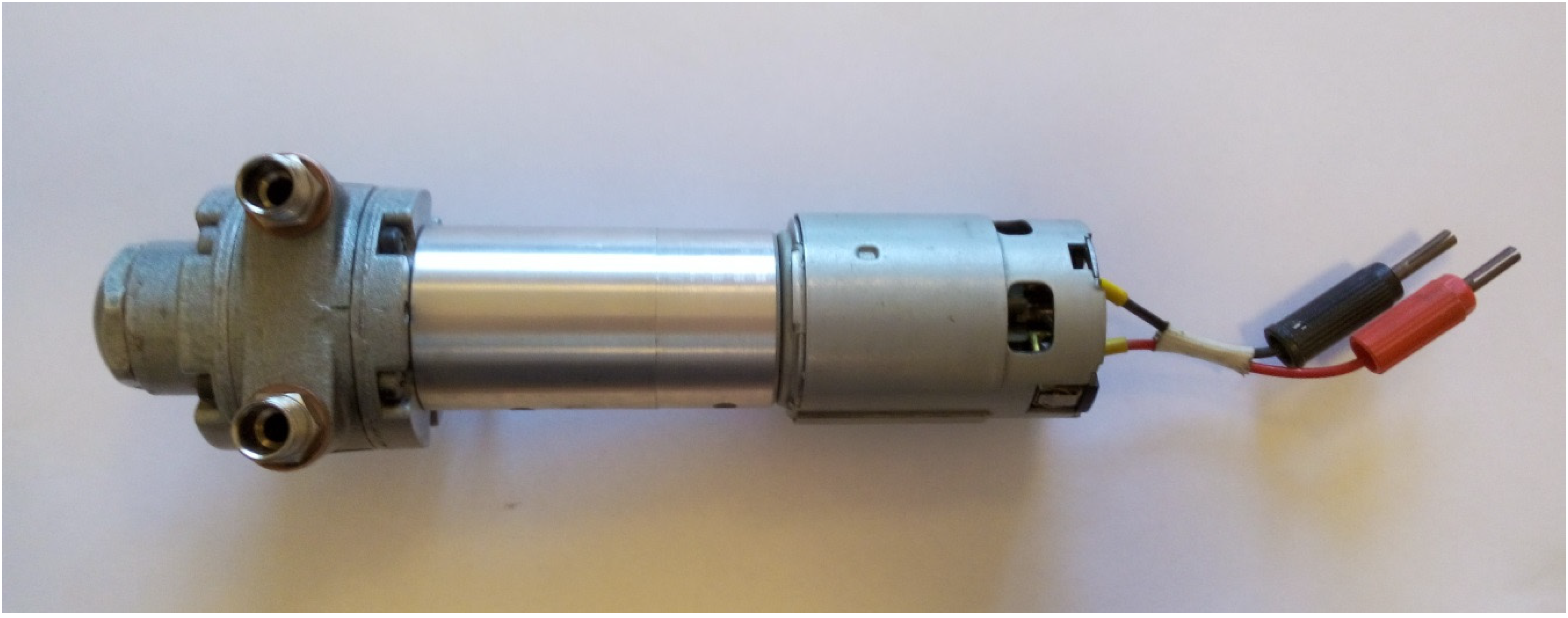
There are no ORC-dedicated vane expanders available, however, standard pneumatic air motors can be easily adapted for this task.
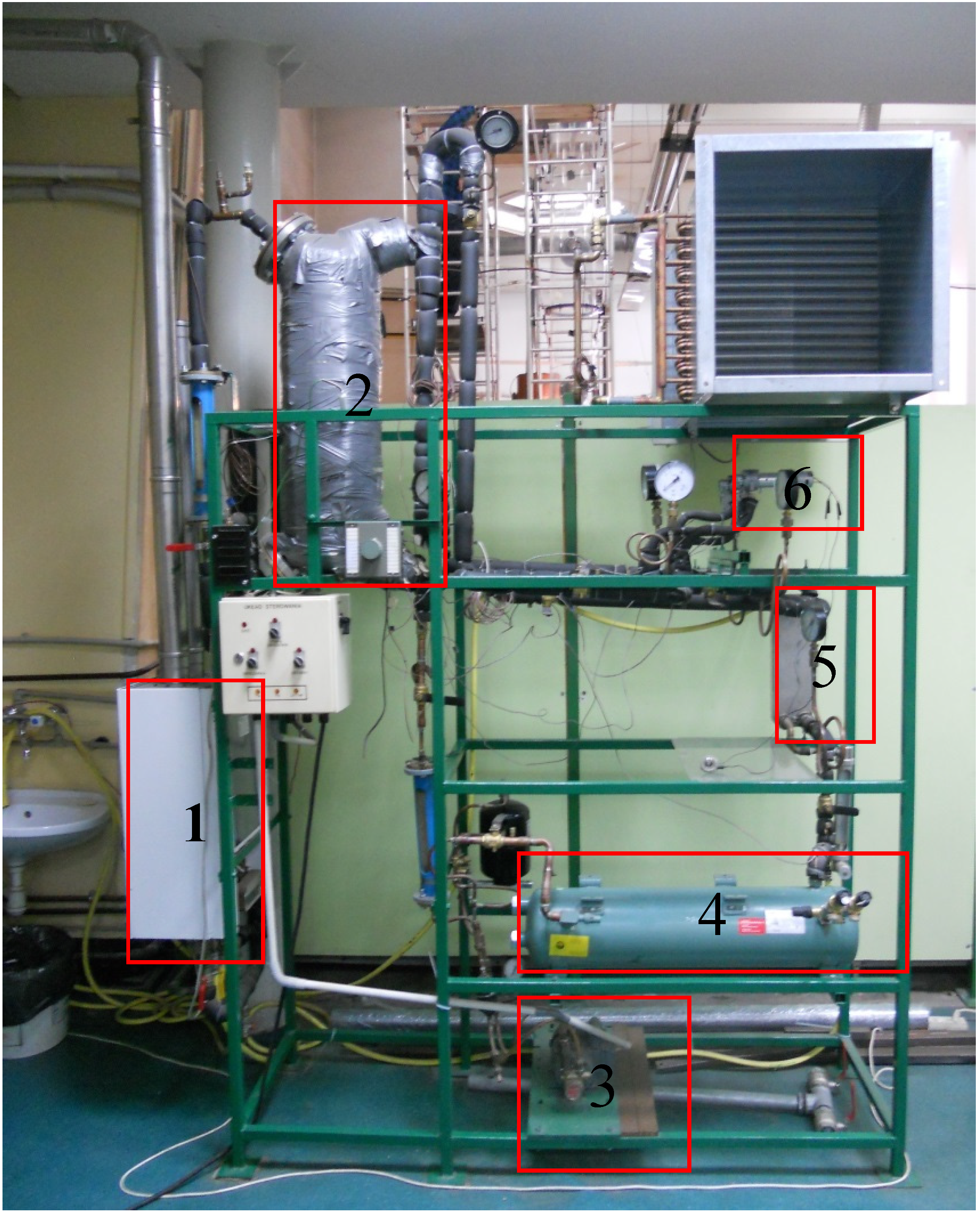
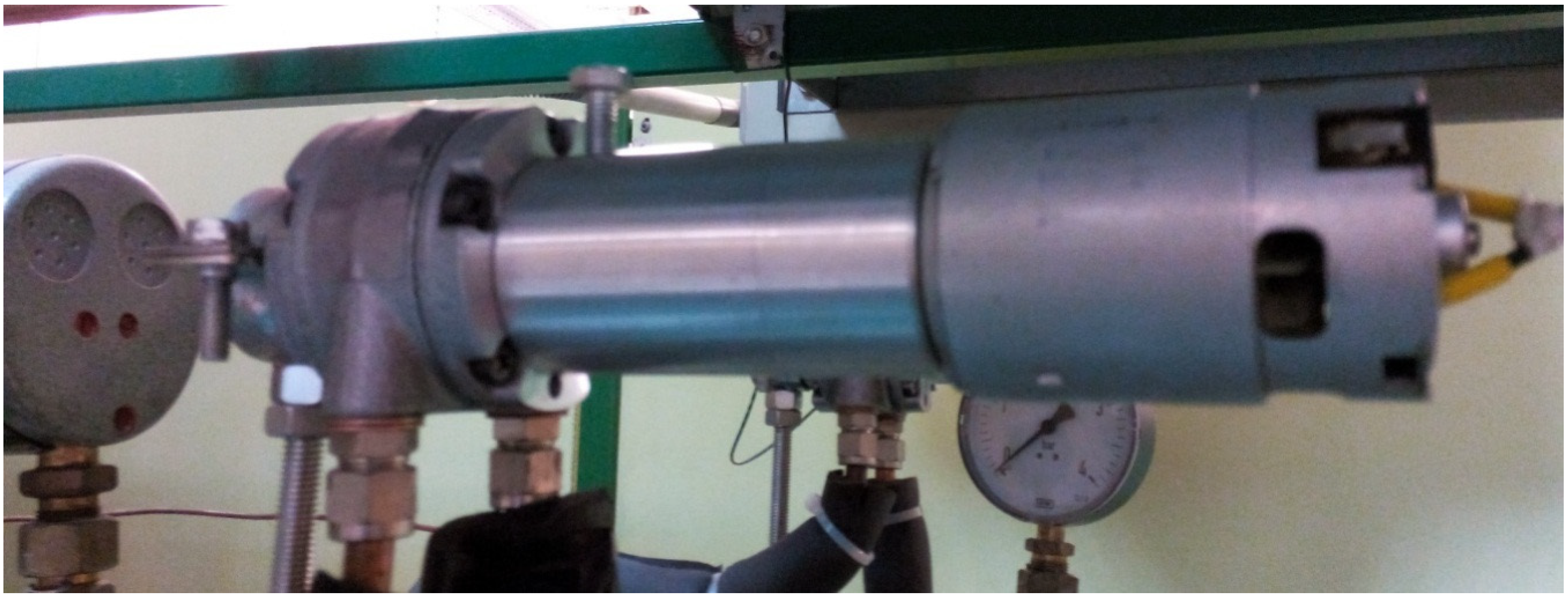
Encouraged by the abovementioned advantages of vane expanders, the author decided to examine their practical application in a micro-ORC system. For this purpose a test-stand, described in detail later in this article, was designed and set up. The test-stand design allows research into different operating conditions due to its adaptive heat source. A series of experiments was performed using the test-stand. Analysis concerning the test-stand operation under variable amount of working fluid conditions was described by the author in his earlier article [
15]. The present study concerns research related to vane expander operation under the different heat source conditions. The following aspects are treated in the following sections: the assembly and mathematical description of a rotary vane expander and the results of experiments.
2. The Assembly and Mathematical Description of a Rotary Vane Expander
As an introduction to the discussed issues the assembly and the mathematical description of a rotary vane expander is presented in the following section.
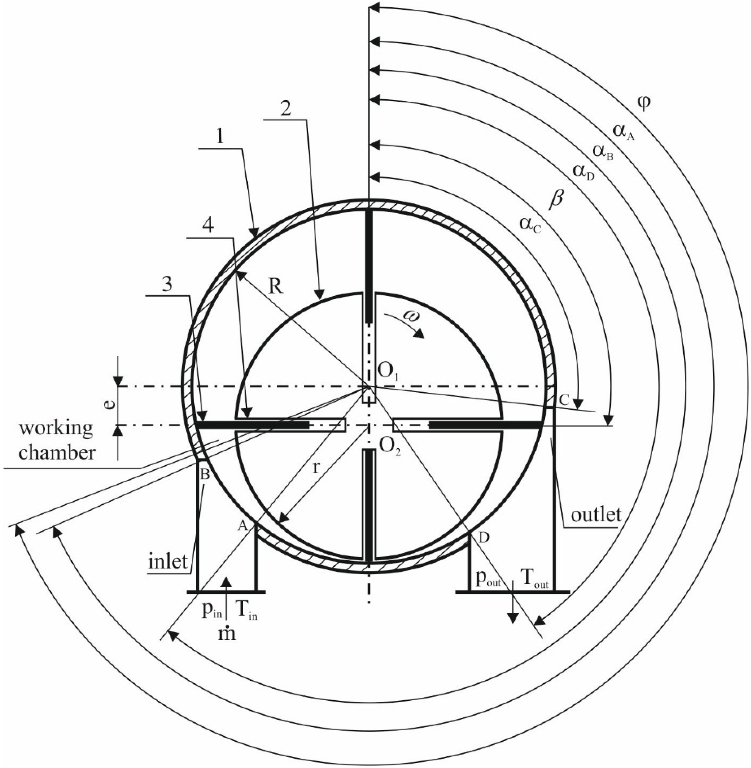
Figure 1 shows a simplified scheme of the multivane rotary expander. Assembly of the expander can be described on the basis of this figure.
Figure 1.
The scheme of the multivane rotary expander.
Figure 1.
The scheme of the multivane rotary expander.
The main machine elements are a cylinder (1) and the rotor (2). The diameters of the rotors and cylinders may vary, depending mostly on the machine power. Small (0.02–0.05 m) diameters are characteristic of small power expanders (such as engines in small pneumatic tools, e.g., grinders or drillers), while larger diameters (0.05–0.2 m) are used in large power expanders (e.g., pneumatic engines in mixers). The rotor is mounted eccentrically in the cylinder on bearings (rolling or slide). Eccentricity can also vary, depending on the machine design. Large (0.01–0.15 m) eccentricity increases the volume of the working chambers which can improve the machine power, but can also increase the internal leakage and reduce the efficiency. Small eccentricity (lower than 0.01 m) decreases the working chambers’ volume and machine power, but increases the efficiency due to the decreasing internal leakage. Vanes (3) are placed in perpendicular or inclined slots (4) milled in the rotor (see
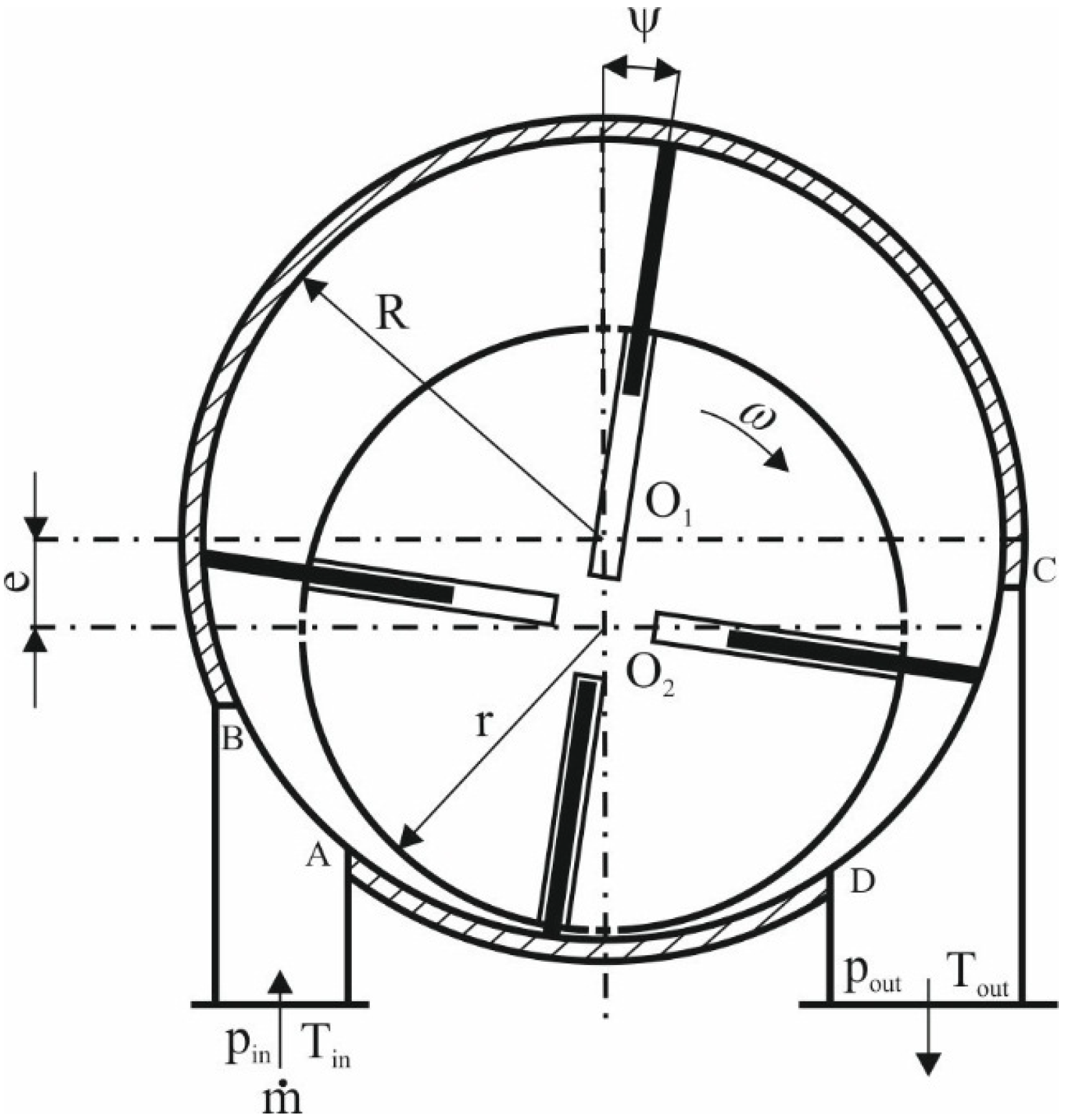
Figure 1). The vanes remain in close contact with the cylinder as a result of centrifugal force, or are pressed to the cylinder surface with help of other elements e.g., springs or rings. Inclined slots are preferable as the centrifugal force acting on the vane during rotor movement increases and the risk of jamming the vane in the slot decreases. Also, the energy dissipation by friction in the case of inclined vanes is 30%–60% smaller than in the case of perpendicular vanes [
16]. The number of vanes may vary, depending on the machine design and power. More vanes can improve the continuity of the machine operation by increasing the number of coexisting working chambers, but can also decrease the efficiency by adding additional friction. The optimum is acknowledged to be between 4 and 20 vanes, but it ultimately depends on specific device design and application [
16]. The cylinder is usually made of cast aluminum alloy. While the rotor is usually made of rolled steel. Vanes are made of different materials, depending on the machine type. The commonly used materials are steel, graphite, titanium and cured silicon doped with graphite. The inlet and outlet port edges (A, B, C and D in
Figure 1) are referred to as the machine “steering edges”. The proper arrangement of these edges has a significant influence on the expander operation. The inlet port edges (defined by α
A and α
B angles in
Figure 1) and inlet port diameter should be arranged in such a way that gas can flow into the machine working chamber without significant pressure losses. The outlet port edges (defined by α
C and α
D angles in
Figure 1) and outlet port diameter should be arranged in such a way that gas can be evacuated from the chamber quickly and without whirls. This issue is comprehensively described in [
17].
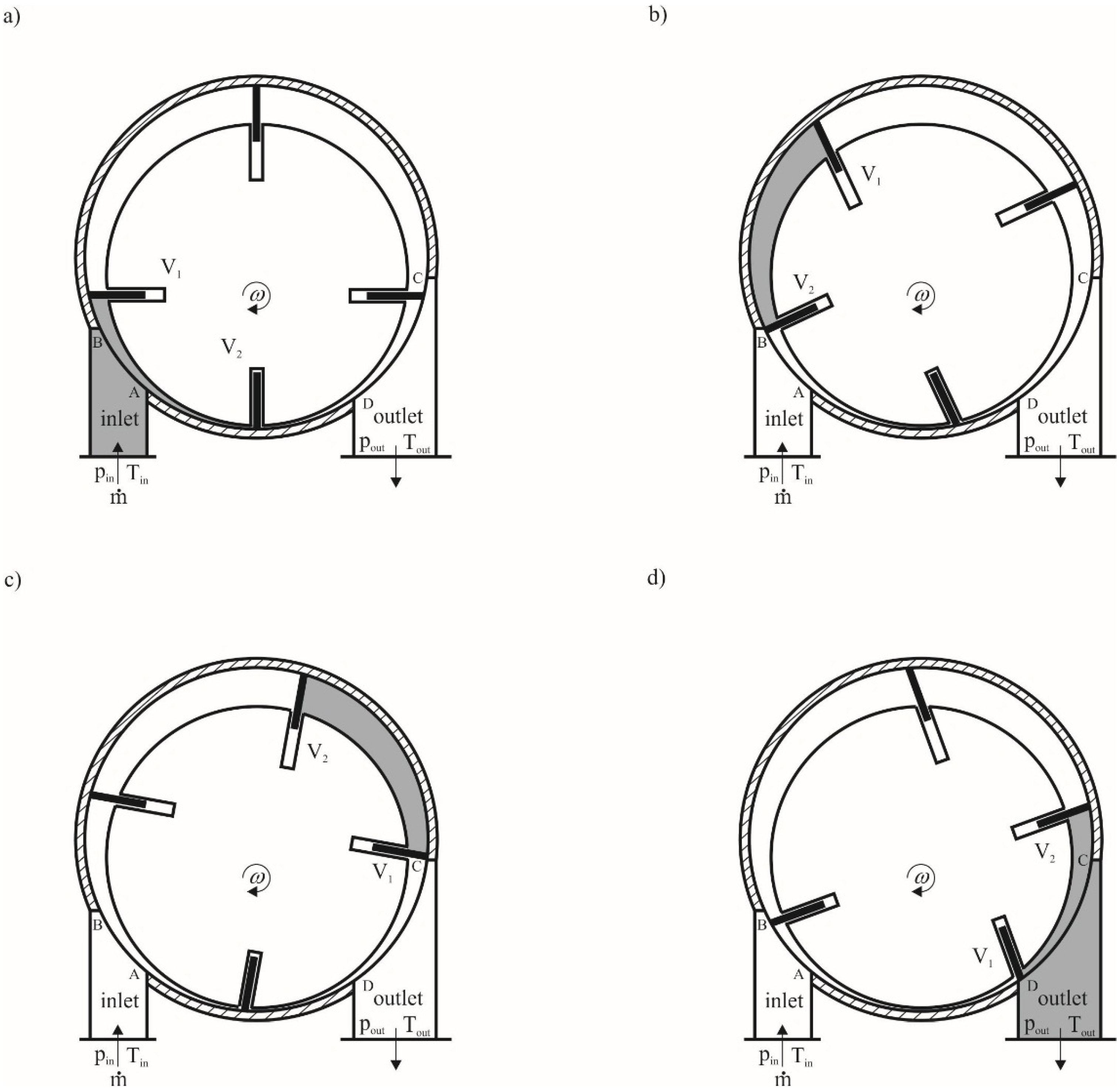
The working principle of a multivane expander is very simple and it can be described on the basis of
Figure 2. The working fluid with thermodynamic properties
pin and
Tin flows into the rotating working chamber through an opening formed by the inlet port (limited by A and B) and the surfaces of the cylinder, rotor and the two vanes (V
1 and V
2) (see
Figure 2a). The filling of the chamber ends when the V
2 vane passes B edge (see
Figure 2b). This way, a portion of gas is enclosed within the rotating chamber. Gas pressure, exerted on the vane results in rotor movement. The vanes remain in close contact with the cylinder as a result of the centrifugal force resulting from the rotor rotational movement. During rotor movement volume of the working chamber increases and the gas expands (see
Figure 2c). When the V
1 vane reaches the C edge the chamber opens and the gas starts to flow toward the outlet port (limited by C and D) (see
Figure 2d). The expansion ends when the values of thermodynamic properties of the gas in the chamber equals those at the outlet port
pout and
Tout. When the V
2 vane reaches the D edge, the working chamber closes again and after the minimum value of the volume is reached, the chamber is filled again with gas. The expander working cycle is completed at this point. In the multivane expander many working chambers coexists in a one moment of time and the gas is expanded concurrently in all of the chambers. This feature results in continuous machine operation.
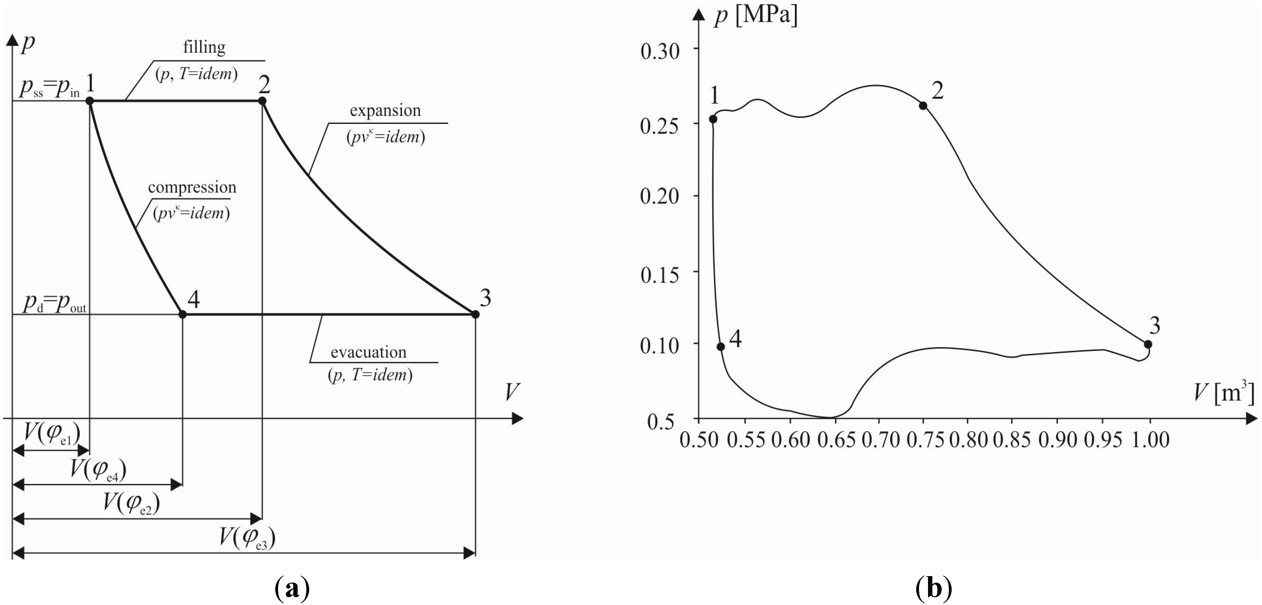
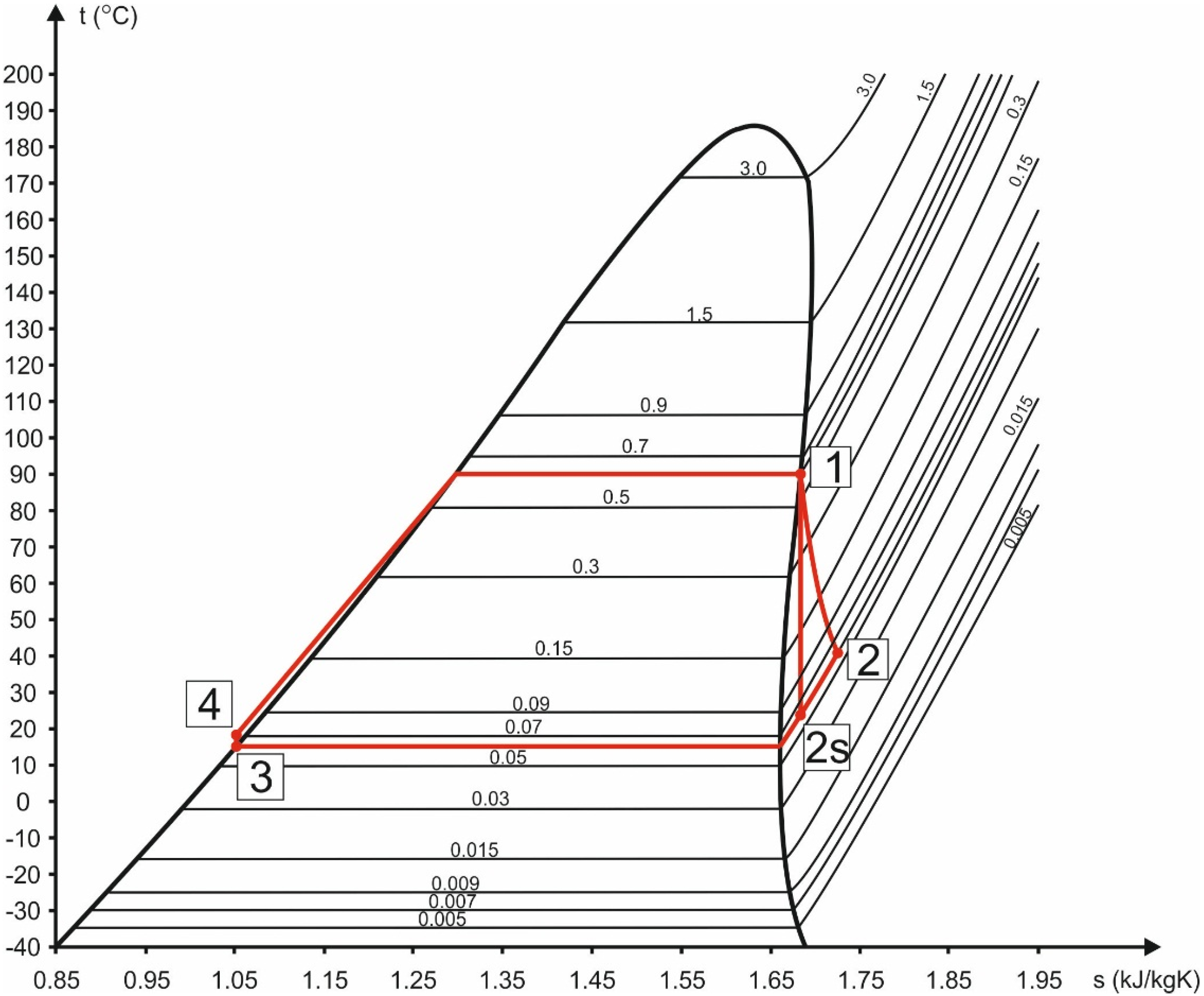
The ideal vane expander working cycle (see
Figure 4a) is formed by four ideal thermodynamic processes: isobaric filling (1–2), polytropic expansion (2–3), isobaric evacuation (3–4) and polytropic compression (4–1). The real working cycle (see
Figure 4b) is different from the ideal cycle. The curved lines depicting the processes result from energy dissipation phenomena. The most important are under and overexpansion, pressure losses during filling and evacuation, friction, internal leakages, and heat transfer from the machine surface to the surroundings.
Figure 2.
The process of the gas expansion in the multivane expander. (a) The working chamber filling; (b) end of the working chamber filling; (c) end of the expansion; (d) evacuation of the gas from the working chamber.
Figure 2.
The process of the gas expansion in the multivane expander. (a) The working chamber filling; (b) end of the working chamber filling; (c) end of the expansion; (d) evacuation of the gas from the working chamber.
Figure 3.
The scheme of the multivane rotary expander with inclined vanes.
Figure 3.
The scheme of the multivane rotary expander with inclined vanes.
Figure 4.
The comparison between the ideal and the real multivane expander thermodynamic cycles in the p-V plane [
15]. (
a) Ideal cycle; (
b) real cycle.
Figure 4.
The comparison between the ideal and the real multivane expander thermodynamic cycles in the p-V plane [
15]. (
a) Ideal cycle; (
b) real cycle.
In the following a brief mathematical description of the multivane expander is presented. The machine working parameters are related with the geometrical dimensions (the cylinder diameter
D, the rotor diameter
d, the cylinder length
L, and the number of vanes
z). It is generally assumed that these values are related to each other as follows [
18]:
e = (0.9–0.15)R,
L = (3–4.5)R.
The volume of a working chamber whose position is defined by the angle φ (see
Figure 1) can be described by the equation:
where
A(φ) is a cross section of the working chamber, ρ is the length of the variable cylinder radius-vector, β is the angle of vane inclination to the rotor radius.
The length of the variable cylinder radius-vector whose position is defined by the angle φ can be described by the equation:
where
e is the eccentricity.
The combination of Equations (1) and (2) gives the following expression for the volume of a working chamber:
The expansion of a gas is a polytropic process, thus the gas pressure in the chamber can be described by the equation:
where
Vmax is the maximum volume of the working chamber,
n is the polytropic exponent.
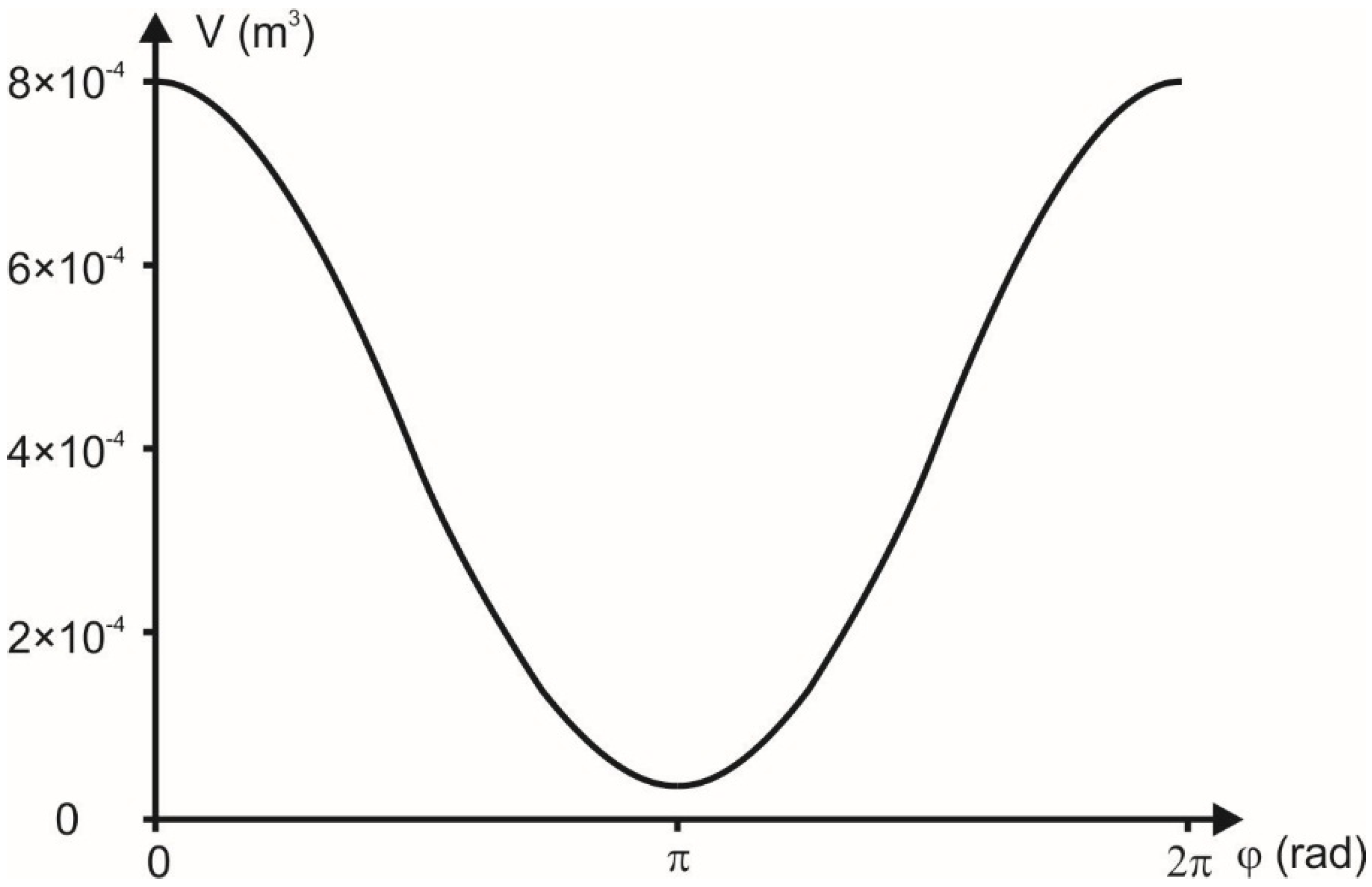
Figure 5 shows the relationship between the volume of a working chamber and the angle of the rotor rotation (φ). The graph is valid under the assumption that:
R = 0.1 m,
e = 0.09R,
L = 3
R.
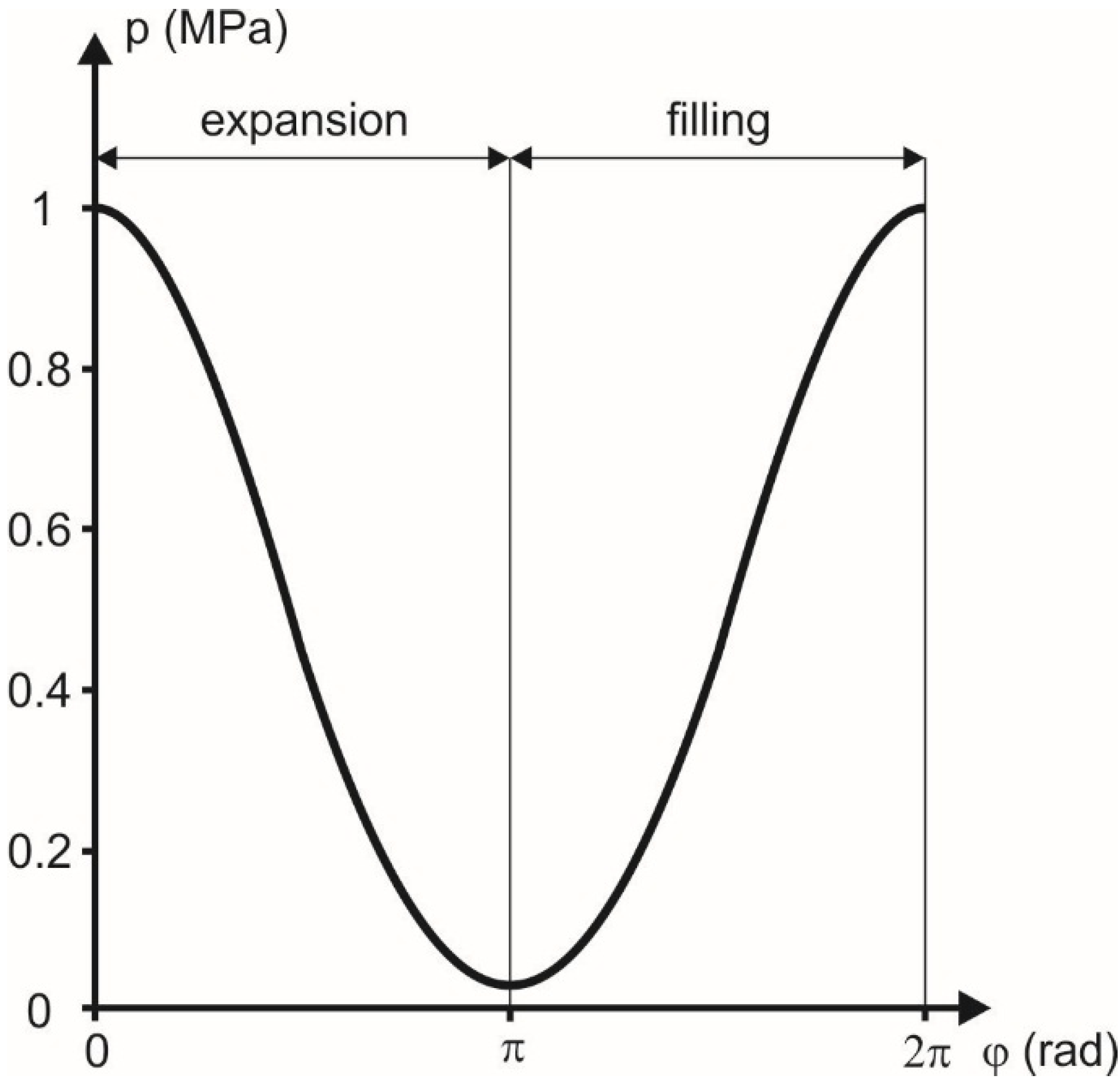
Figure 6 shows the variation of pressure in a working chamber. The graph is valid under assumption that polytropic exponent
n = 1.1 and the pressure at the expander inlet is
pin = 1 MPa.
Figure 5.
The relationship between the volume of a working chamber and the angle of the rotor rotation (R = 0.1 m, e = 0.09R, L = 3R, φ = 0°–360°).
Figure 5.
The relationship between the volume of a working chamber and the angle of the rotor rotation (R = 0.1 m, e = 0.09R, L = 3R, φ = 0°–360°).
Figure 6.
The variation of the gas pressure in the working chamber (n = 1.1, φ = 0°–360°).
Figure 6.
The variation of the gas pressure in the working chamber (n = 1.1, φ = 0°–360°).
The theoretical volumetric flow rate through a multivane expander can be obtained with the equation:
where
R (m) is the cylinder radius,
e (m) is the eccentricity,
L (m) is the cylinder length,
n (rev/s) is the expander rotational speed.
The theoretical volumetric mass flow rate through a multivane expander can be obtained with the equation:
where ρ
in (kg/m
3) is the gas density at the inlet to the expander.
The theoretical power output of a multivane expander can be obtained with the equation:
The combination of Equations (5)–(7) gives the following expression for the theoretical power output:
The volumetric flow rate through a multivane expander is dependent on the dimensionless coefficient λ representing the energy losses in the expander and it can be obtained with the equation:
λ coefficient can be obtained with the following equation:
where λ
V is the clearance volume coefficient; λ
T is the throttling coefficient, λ
L is the leakage coefficient. The calculation procedure for the above coefficients is very complex and has been comprehensively described in [
18].
Usually, the coefficient λ is determined with the following simplified empirical equation:
where
K = 0.05—for large (1 kW and more) expanders,
K = 0.1—for small (up to 1 kW) expanders,
pout (Pa) and
pin (Pa) are the pressure of the gas at the inlet and the outlet of the expander, respectively.
The combination of Equations (8) and (9) give the following expression for the power output:
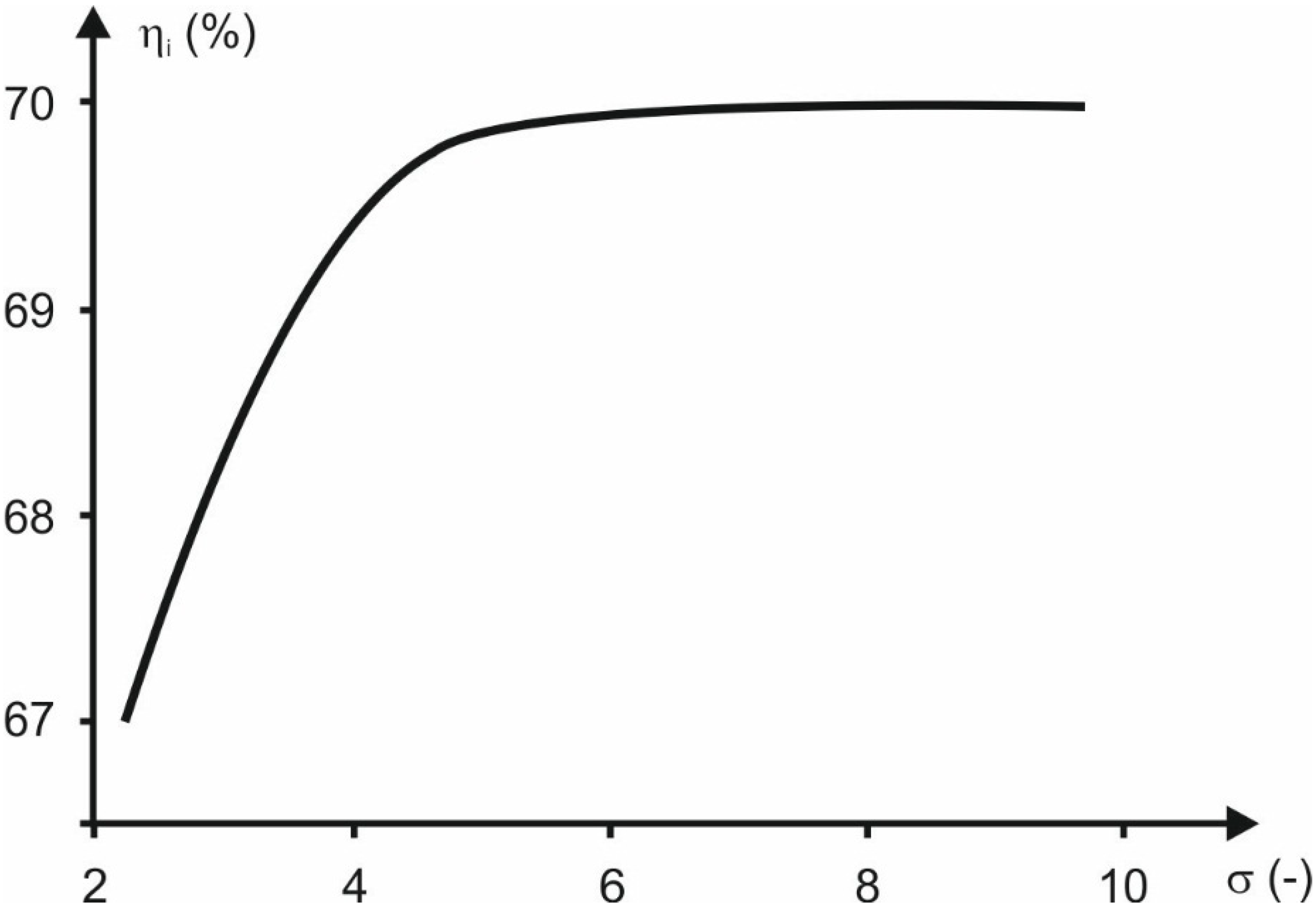
Gas can be expanded in the expander within a limited pressure range. The range can be defined by the expansion ratio:
The multivane expander output power mainly depends on the expansion ratio [
17], which is a characteristic feature of the machine and it can reach different values. Practically it is within the range of σ = 3–10 [
19].
The power of a multivane rotary expander can also be obtained with the equation:
where
hin and
hout are the specific enthalpy of the working fluid at the inlet and the outlet of the expander, respectively.
The internal efficiency of a multivane rotary expander can be obtained with the equation:
where
hout s is the specific enthalpy of the working fluid at the outlet of the expander under the assumption that the expansion is isentropic.
The total efficiency of a multivane expander is dependent on many energy dissipation processes taking place in the machine during operation. The most important are [
18]:
Friction between the vane and the cylinder,
Leakages between the working chambers,
Heat dissipation from the casing,
Pressure fluctuations during filling and evacuation.
According to the Reference [
18] the mechanical efficiency of the multivane expanders varies from η
m = 0.7–0.75 (machines with perpendicular vanes) to η
m = 0.75–0.82 (machines with inclined vanes).
4. Summary and Conclusions
This paper presents a theoretical and experimental analysis of operation of a the micro-ORC rotary vane expander under variable heat source temperature conditions. Such systems are suitable for dispersed cogeneration of heat and electric power in small scenarios such as households or farms.
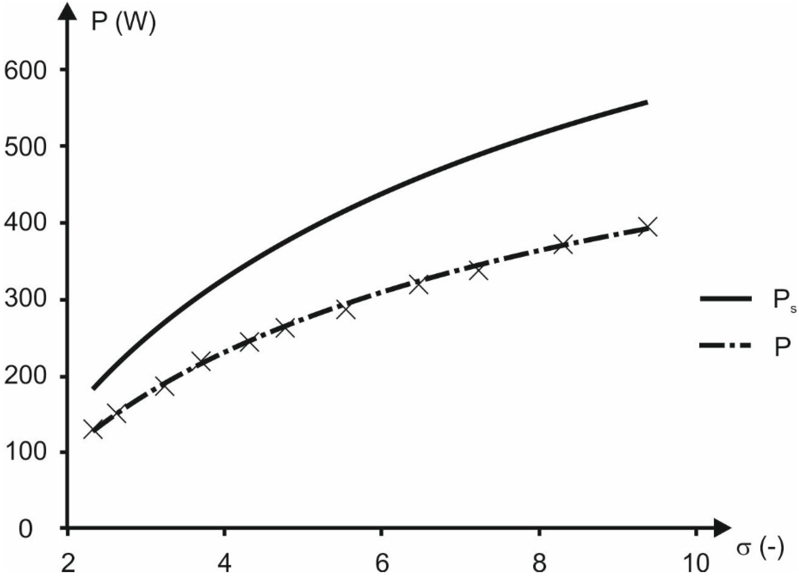
The theoretical analysis of rotary vane expanders shows that the power output is mainly dependent on the expansion ratio (the ratio of the working fluid pressure at the inlet and outlet from the expander). The output power increases with the increasing expansion ratio. The theoretical treatment also includes a mathematical description of the expander, together with the thermodynamic descriptions. Examples of output power calculations complete the treatment.
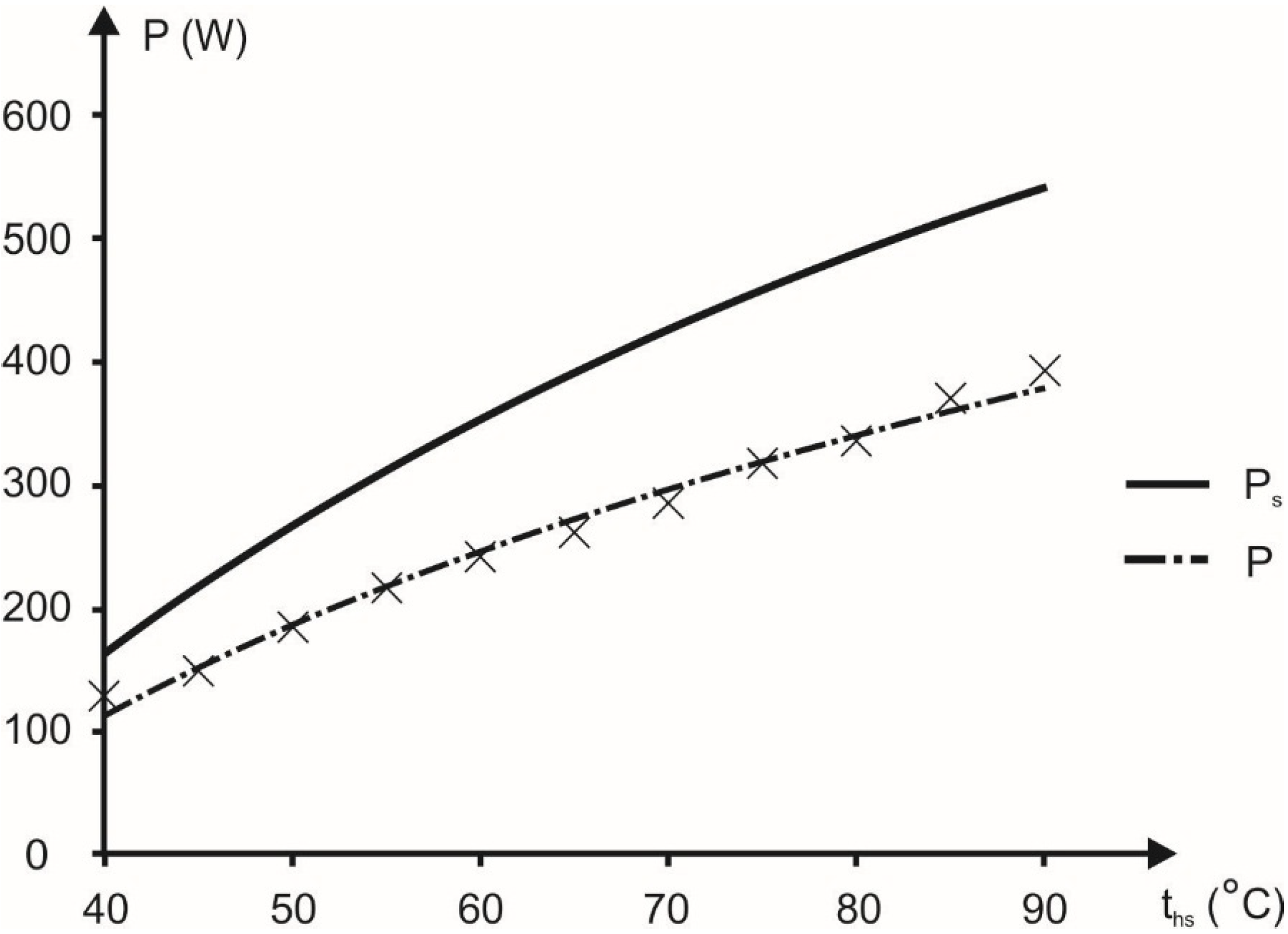
Moreover, the experimental results related to the micro multivane expander proved that the expander power output is dependent on the heat source temperature and expansion ratio. The experiments show that commercially available multivane rotary expanders can be applied in micro ORC systems after suitable modification. The experimental results also proved that with the application of the multivane expander it is possible to recover waste heat from very low temperature (40–90 °C) heat sources. This is possible due to the multivane expander features, namely the ability to operate with low working fluid pressures and flows. This is not possible in the case of turbines and micro turbines, where high velocities and high working fluid flows are needed. Multivane expanders are also a good alternative to the other types of the volumetric expanders applied in a small power ORC systems e.g., screw, scroll and piston, as they are compact, low weight, simple in design and cheap. Moreover multivane expanders have large power output relating to their dimensions and weight when compared with earlier mentioned volumetric expanders. The experiments were performed on a very small device in a limited range of pressures. However, for larger multivane expanders, the shape of the characteristic output power, presented in
Figure 12 and
Figure 13, will be similar as presented in [
16]. The performance and quality of operation of the multivane expander depends on the machine design and the energy dissipation processes. The most important are internal and external leakages, internal friction, and heat transfer from the machine surface to the surroundings. Thus the design optimization of the multivane expander should include proper arrangement of the machine steering edges, and improvements to the sealing and machine insulation [
17].
The application of multivane expanders can provide an opportunity for a large increase in the market share of domestic ORC systems. The simplicity of these expanders translates into easy service, operation and low system cost, what are very important in the case of domestic devices. The application of turbines in such systems is difficult and results in high manufacturing costs.
Encouraged by the advantages of these machines, the author decided to continue the research on the application of the multivane expanders in ORC systems. The author has designed a new prototype of a multivane expander-based micro ORC system combined with a heat storage system. The theoretical analysis of this system is comprehensively presented in [
22]. The new prototype assembly allows one to change the working fluid. The construction of the prototype is underway. The experiment will be performed using classic working fluids
i.e., R123 and R245fa, as well as modern alternatives,
i.e., SES36, R1234yf and R1234ze.


