Abstract
Due to the possibility of putting a large number of modules consisting of switches and capacitors connected in series, the modular multilevel converter (MMC) can easily be scaled to high power and high voltage power conversion, which is an attractive feature for filter-less and transformer-less design and helpful to achieve high efficiency. However, a significantly increased amount of sub-modules in a MMC may increase the requirements for sensors and also increase the risk of failures. As a result, fault detection and diagnosis of MMC sub-modules are of great importance for continuous operation and post-fault maintenance. Therefore, in this paper, an effective fault diagnosis technique for real-time diagnosis of the switching device faults covering both the open-circuit faults and the short-circuit faults in MMC sub-modules is proposed, in which the faulty phase and the fault type is detected by analyzing the difference among the three output load currents, while the localization of the faulty switches is achieved by comparing the estimation results by the adaptive observer. In contrast to other methods that use additional sensors or devices, the presented technique uses the measured phase currents only, which are already available for MMC control. In additional, its operation, effectiveness and robustness are confirmed by simulation results under different operating conditions and load conditions.
1. Introduction
Recent years, renewable energies, especially the off-shore wind energy and marine energies, have been drawing a lot of interest due to their features of low pollution, sustainable development, few disturbances and large capacity, which have made the expansion of energy plants from onshore to offshore the trend. Modular Multilevel Converter-High Voltage Direct Current (MMC-HVDC) systems [1,2,3,4,5,6] are gradually becoming a possible solution compared to the traditional power transmission technology for connecting offshore energy plants located at longer distances to the transmission grids due to a series of merits compared to other existing power transmission systems such as higher output voltage levels, modular construction, larger maintenance intervals, improved reliability and reduced costs. However, due to the high maintenance/repair cost at the distant offshore plant, the reliability has become one of the most important challenges for MMCs, where generally a large number of power switching devices are used and each of these devices may be considered as a potential failure site, so obviously, it is essential to detect and locate any faults within a short time after the fault occurrence with minimal sensors.
Strictly, the detection process should be divided into the monitoring stage and the identification stage, where the former is used to supply the information about whether the operation of the system is normal or not, while the latter is activated only when the system is diagnosed as abnormal to identify the fault type and fault location. Given the large numbers of identical cells and the symmetrical structure of the converter, acquiring the fault location in a MMC is challenging. A direct approach to detect faults is to add additional sensors to each semiconductor switching device, to each cell, or to use a gate drive module capable of detecting faults and providing feedback [7]. This method combines the monitoring process and the identification process and the time consumed in the detection is quite short, however, it is a quite inefficient way to detect faults as the faults are detected manually which has low efficiency, especially when a large number of switching devices and cells are involved. Moreover, these additional sensors and signals increase not only the cost, but also the implementation complexity. Lezana [8] detected the system by analyzing the magnitude of the switching frequency component of the output phase voltage. This method is complex to implement and it is easy to get the wrong diagnosis in transient operation due to the very small angle difference caused by the high switching frequency. Moreover, the faulty switching device cannot be located. Yazdani [9] proposed that the root mean square value of the output phase voltage can be used to monitor the system, but this it is time-consuming. A sliding mode observer (SMO)-based fault detection method for MMC is proposed in [10], which is also time-consuming. Deng [11] employed the Kalman filter (KF) to detect open-circuit faults in MMC sub-modules. However, this is useless for short-circuit faults happening in the MMC. Liu [12] proposed the Wavelet Transform (WT) to detect short-circuit faults in MMC sub-modules, but not open-circuit faults. The artificial intelligence methods such as Fast Fourier Transform (FFT) [13,14] Discrete Fourier Transform (DFT) [15] and Neural Network (NN) [16] can also be used to detect the open-circuit faults and short-circuit faults in MMCs and the only problem then is the long training time. To avoid the mentioned disadvantages, in this paper, a fault detection and localization method based on a nonlinear adaptive observer for both open-circuit faults and short-circuit faults is proposed for an MMC to improve the reliability. The establishment of an adaptive observer of the MMC, used to estimate the behavior of the MMC under different faulty operation conditions, is based on the nonlinear dynamical system theory [17]. The fault characteristics of the sub-modules undergoing both open-circuit and short-circuit failures of the power semiconductor devices are analyzed in Section 2. The faulty phase of the MMC is detected in Section 3 by evaluating the output currents and this section provides simultaneously information on the fault type, i.e., open-circuit fault in T1, open-circuit fault in T2 or short-circuit fault. The adaptive observer is adjusted in Section 4 based on the detection results and then additional activities are performed in order to localize the specific faulty module. The proposed method can effectively and precisely detect the fault types as well as locate the faulty modules and faulty switching devices, even under various operation transmission power ratings without increasing the implementation and calculation complexity, which is shown in the simulation results in Section 4. Finally, the conclusions are presented in Section 5.
2. Principle and Fault Mechanism Analysis for MMC
2.1. Operation Principle of MMC
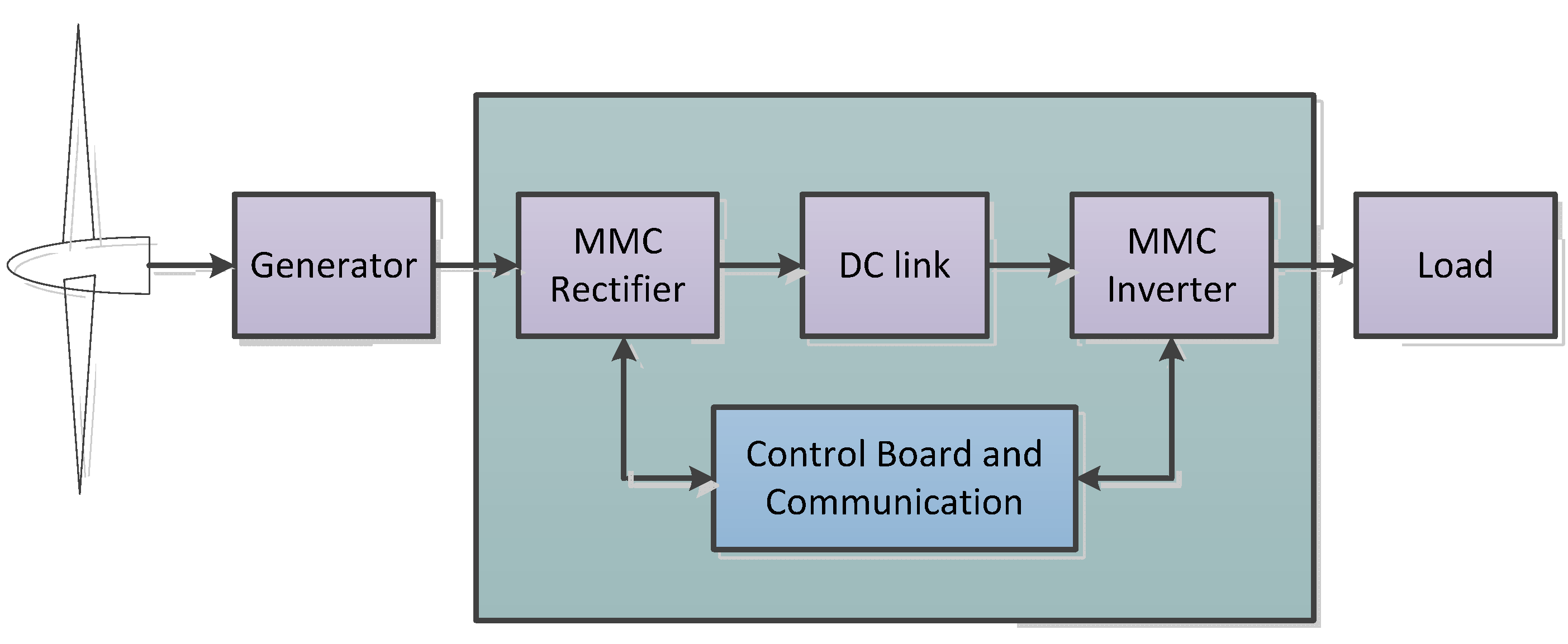
A wind power generation HVDC transmission system, as shown in Figure 1, is used in this paper to illustrate the MMC state observer design process under different load types. Ten wind turbines (XD93-2000 kW) with 2 MW rated active power are to be connected by the MMC converter to make up a wind farm. Both the generator-side converter and the grid-side converter employ the three-phase MMC and the DC link voltage in this system is maintained by the sum of sub-module voltages in the converter leg.
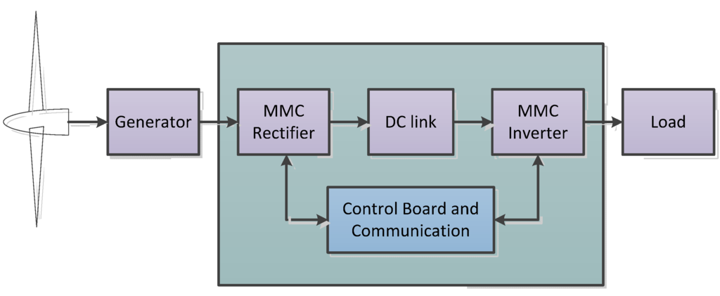
Figure 1.
Wind power generation HVDC transmission system.
Figure 1.
Wind power generation HVDC transmission system.
The MMC, as shown in Figure 2, consists of three phases and each phase has two arms, being composed of N sub-modules and a series connected inductor. These sub-modules are identical and generally half-bridge in each arm. Each sub-module consists of two insulated-gate bipolar transistors (IGBTs) T1, T2 and two antiparallel connected diodes D1, D2, as well as an energy storage capacitor C. The dynamical mathematical equations which characterize the MMC in Figure 2 are studied below.
The upper arm currents ip,k and lower arm currents in,k in phase k are expressed below in Equations (1) and (2). The arm currents consists three parts: the dc component which is one third of the dc current idc, the ac component which is the half of the output ac current ik and the circulating current icir,k. All of the variables are illustrated in Figure 2.

Figure 2.
Structure of the Modular Multilevel Converter (MMC).
Figure 2.
Structure of the Modular Multilevel Converter (MMC).
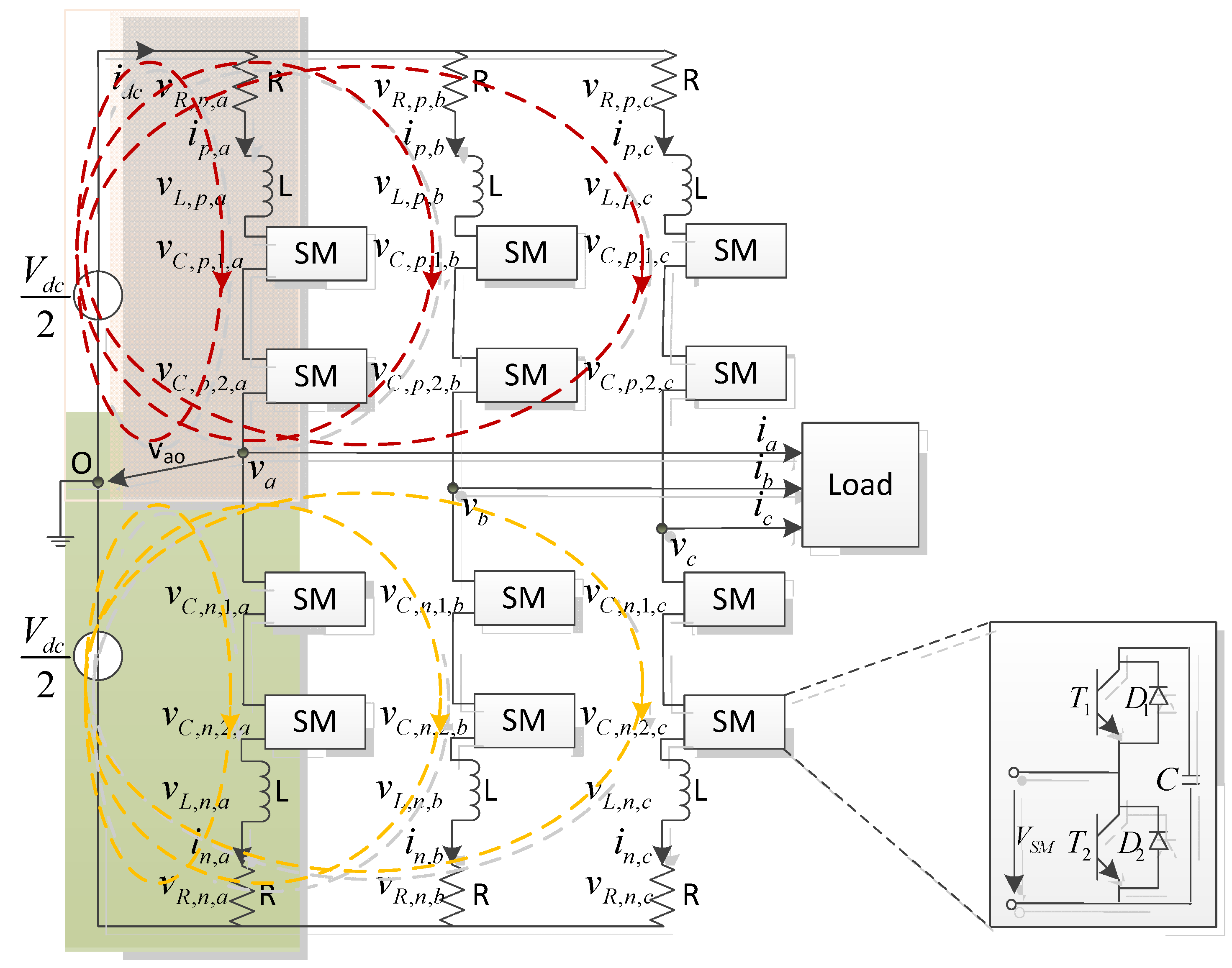
According to the Kirchhoff voltage law, the voltage relationships are obtained from the analysis of the upper loop and lower loop which are comprised by each arm and the DC source, respectively. vc,p,i,k and vc,n,i,k are the capacitor voltages of the ith module in the upper arm and the lower arm in phase k, vL,p,k and vL,n,k are the inductor voltages in the upper arm and the lower arm in phase k, vR,p,k and vR,n,k are the resistor voltages in the upper arm and the lower arm in phase k, and vk are the output phase voltages in phase k, Sp,i,k and Sn,i,k are the gating signals driving the upper switches in the modules in the upper arm and lower arm, respectively:
The voltages of the capacitor in those modules, the inductor currents and the voltages across the resistors in the arms are presented in Equations (5)–(10):
The subscript p and n are the upper arm and lower arm, i is the number of capacitors in each arm, k = a, b, c represent the three phases.
2.2. Fault Mechanism of MMC
There are two different types of the switching device fault in a sub-module: open-circuit fault which appears due to lifting of the bonding wires in a switch module caused by over-temperature or aging and usually does not cause additional serious damage to the system if the protection system functions well; short-circuit faults are caused by wrong gating signals, overvoltage, or high temperature and could cause additional damage to other components in the circuit, so the short circuit fault should be treated fast and carefully. Generally, the hardware overcurrent protection which stops the operation of the system is the most common solution for short-circuit faults [18]. However, for MMC, the overcurrent appears in the faulty module rather than flowing through the whole arm or phase which means it is the faulty module that needs to be bypassed by the action of overcurrent protection devices and the system operation can continue without stopping. Open-circuit and short-circuit fault detection and localization of a specific power switch present some difficulties since an open-circuit fault or short-circuit fault in power switches with the same position in different modules, associated to the same arm, causes identical arm current profiles. The failure configurations of the open-circuit and short-circuit fault in a sub-module concerning on the failure of the switching devices T1, T2 are shown in Figure 3.
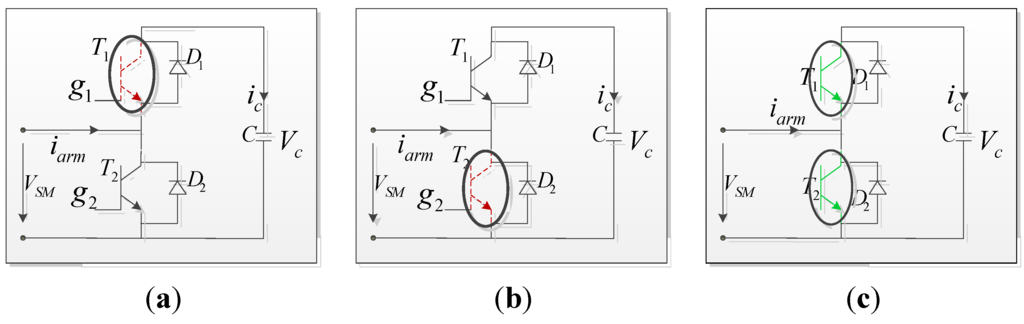
Figure 3.
Failure configurations of the modules. (a) open-circuit fault in upper IGBT; (b) open-circuit fault in lower IGBT; (c) short-circuit fault in upper or lower IGBT.
Figure 3.
Failure configurations of the modules. (a) open-circuit fault in upper IGBT; (b) open-circuit fault in lower IGBT; (c) short-circuit fault in upper or lower IGBT.
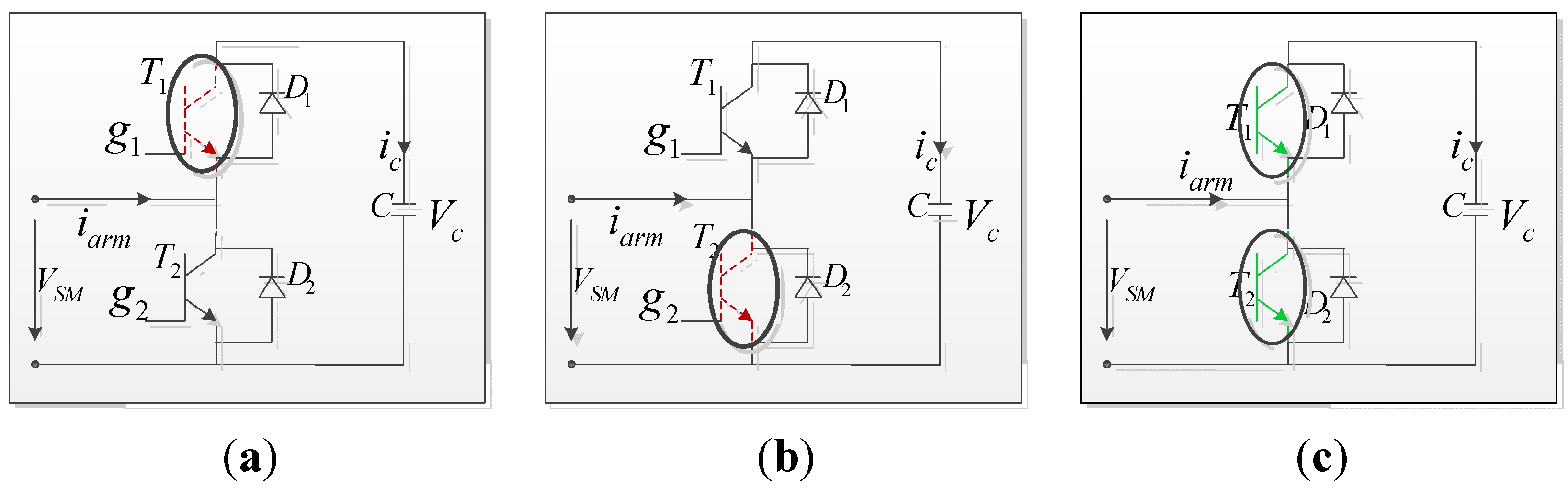
There are four statuses in each module considering the normal condition, open-circuit faults and short-circuit faults:
- (1)
- Normal operation: In normal operation, as listed in Table 1, when the arm current ip(n),k is positive, if T1 is turned on, T2 is turned off in the ith module which means Sp(n),i,k = 1, the current flows through D1 and C, the capacitor is charged; otherwise, T1 is turned off, T2 is turned on, the current will go through T2 and the capacitor voltage maintains stable; when ip(n),k is negative, T1 is turned off, T2 is turned on, the current flows through D2; oppositely, Sp(n),i,k = 0, the current will go through T1 and C, the capacitor is discharged;

Table 1.
Four Working Regions of Sub-Module in MMC.
| State No. | Current | Status | Gating Signal | Arm Current Goes Through | Capacitor | Capacitor Voltage |
|---|---|---|---|---|---|---|
| 1st | ip(n),k > 0 | T1 on, T2 off | Sp(n),i,k = 1 | D1 and C | Charged | Increased |
| 2nd | ip(n),k > 0 | T1 off, T2 on | Sp(n),i,k = 0 | T2 | Bypassed | Stable |
| 3rd | ip(n),k < 0 | T1 on, T2 off | Sp(n),i,k = 1 | T1 and C | Discharged | Decreased |
| 4th | ip(n),k < 0 | T1 off, T2 on | Sp(n),i,k = 0 | D2 | Bypassed | Stable |
- (2)
- Open-circuit fault in T1 (Figure 3a): as shown in Table 2, the sub-module operates as normal when the arm current ikm > 0, the arm current still goes through D1 and C to charge the capacitor when the gating signal Sp(n),i,k = 1 and the arm current flows through T2 to bypass the capacitor when the gating signal Sp(n),i,k = 0; when ip(n),k is negative, the module is in normal operation when Sp(n),i,k = 0, the arm current flows through D2 and the capacitor voltage is stable; however, when the gating signal Sp(n),i,k = 1, the arm current will be forced to go through D2 instead of T1 and C in the normal condition;
Table 2.
Failure Mechanism of Open-Circuit Fault in T1.
| State No. | Current | Status | Gating Signal | Arm Current Goes Through | Capacitor | Capacitor Voltage |
|---|---|---|---|---|---|---|
| 1st | ip(n),k > 0 | T1 on, T2 off | Sp(n),i,k = 1 | D1 and C | Charged | Increased |
| 2nd | ip(n),k > 0 | T1 off, T2 on | Sp(n),i,k = 0 | T2 | Bypassed | Stable |
| 3rd | ip(n),k < 0 | T1 on, T2 off | Sp(n),i,k = 1 | D2 | Bypassed | Stable |
| 4th | ip(n),k < 0 | T1 off, T2 on | Sp(n),i,k = 0 | D2 | Bypassed | Stable |
- (3)
- Open-circuit fault in T2 (Figure 3b): the open-circuit fault is shown in Table 3, the sub-module operates as normal when the arm current ip(n),k > 0 and Sp(n),i,k = 1, if T1 is turned off, T2 is turned on, the arm current is forced to go through D1 and C to charge the capacitor instead of T2 to bypass the capacitor; when the arm current ip(n),k < 0, the module is in normal operation;
Table 3.
Failure Mechanism of Open-Circuit Fault in T2.
| State No. | Current | Status | Gating Signal | Arm Current goes Through | Capacitor | Capacitor Voltage |
|---|---|---|---|---|---|---|
| 1st | ip(n),k > 0 | T1 on, T2 off | Sp(n),i,k = 1 | D1 and C | Charged | Increased |
| 2nd | ip(n),k > 0 | T1 off, T2 on | Sp(n),i,k = 0 | D1 and C | Charged | Increased |
| 3rd | ip(n),k < 0 | T1 on, T2 off | Sp(n),i,k = 1 | T1 and C | Discharged | Decreased |
| 4th | ip(n),k < 0 | T1 off, T2 on | Sp(n),i,k = 0 | D2 | Bypassed | Stable |
- (4)
- Short-circuit fault in T1 or T2 (Figure 3c): as shown in Table 4, when the short-circuit fault happens in T1 (T2), the sub-module operates as normal if the corresponding IGBT T1 (T2) is turned on and the complementary IGBT T2 (T1) is turned off; when the complementary IGBT T2 (T1) is turned on, the capacitor discharged through the capacitor discharging loop which is formed by the short-circuited T1 (T2), the complementary IGBT T2 (T1) and the capacitor C. Due to the small time constant of the capacitor discharging loop, the capacitor discharged very quickly which leads to the rapid declines of capacitor voltage and the large short-circuit current in the faulty module. Generally the faulty module is bypassed and the arm current goes through the switch used to do overcurrent protection. However, with MMC topology, the arm current will go through D1 to charge C when the arm current is positive and go through D2 to discharge C with negative arm current. The capacitor voltage of the faulty module changes from zero to a small value compared to the normal capacitor voltages.
Table 4.
Failure Mechanism of Short-Circuit Faults in T1 or T2.
| State No. | Current | Status | Gating Signal | Arm Current Go through | Capacitor | Capacitor Voltage |
|---|---|---|---|---|---|---|
| 1st | ip(n),k > 0 | T1 on, T2 off | Sp(n),i,k = 1 | D1 and C | Bypassed | Increased |
| 2nd | ip(n),k > 0 | T1 off, T2 on | Sp(n),i,k = 0 | D1 and C | Bypassed | Increased |
| 3rd | ip(n),k < 0 | T1 on, T2 off | Sp(n),i,k = 1 | D2 and C | Bypassed | Decreased |
| 4th | ip(n),k < 0 | T1 off, T2 on | Sp(n),i,k = 0 | D2 and C | Bypassed | Decreased |
It can be seen that various module performances are caused by different faults which means that the different faults can be identified by analyzing the performance of the system. Moreover, the system performance under fault conditions can be imitated by changing the gating signals which makes the below fault identification possible.
3. Proposed Fault Identification Method for MMC
It is desirable that the fault diagnostic method utilize variables already used by the main control in order to avoid the use of extra sensors and the subsequent increase of the system complexity and costs. Hence, the proposed diagnostic algorithm has, as inputs, the output currents and the corresponding reference current signals, capacitor voltages and the reference voltage signals, which can be easily obtained from the main control system.
The framework of the proposed fault identification method is displayed in Figure 4. This approach first detects faulty phase of the MMC by evaluating the output currents and simultaneously provides information on the fault type, i.e., if it is T1 open-circuit fault, T2 open-circuit fault or short-circuit fault. The adaptive observer is adjusted based on the detection results and then additional activities can be performed in order to localize the specific faulty module.
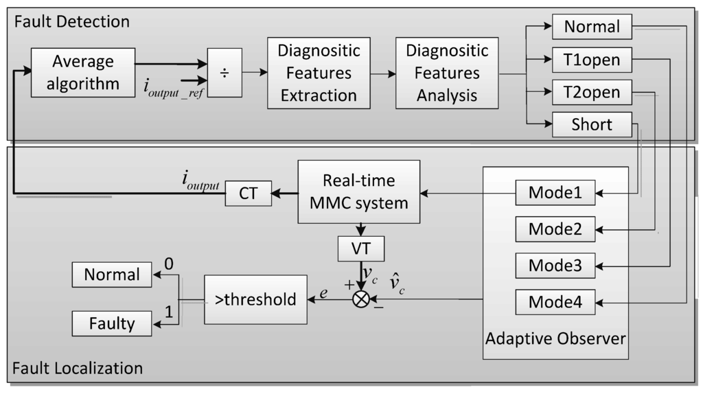
Figure 4.
Framework of the proposed identification method.
Figure 4.
Framework of the proposed identification method.

3.1. Fault Detection
The averaged values of the output currents are calculated first as expressed in Equation (11) by using the reference current signals:
<ik> is the averaged output current can be used to detect the occurrence of failures in any of its phases. However, due to the specific profile taken by the output current waveforms, it is quite difficult to choose a universal threshold since they can vary significantly according to the transmission power level and load conditions. To eliminate those affections, the averaged output currents are normalized:
Three diagnostic features are defined as below:
According to the fault type and the fault occurrence time, these three variables can generate a unique fault signature by comparing the three diagnosis variables. Under normal condition, the output currents are balanced and the three diagnostic features are near-zero. If any open-circuit fault occurs in T1, the current in the faulty phase will increase in a short period when the arm current is negative as the arm current goes through D2 instead of T1 and C, which means the resistance in the faulty phase will be smaller under this situation than under normal condition. At the meantime, the remaining current will be forced to go through the other two phases. Due to the different gating signals in the two normal phases, the remaining current go through them will be different slightly. Therefore, two diagnosis variables in the three will converge to a different value, while the remaining one practically changes slightly.
If any open-circuit fault occurs in T2, the current in the faulty phase will increase in a short period when the arm current is negative as the arm current goes through D1 and C instead of T2, which means the resistance in the faulty phase will be larger under this situation than under normal condition.
If any power switch short-circuit fault occurs, the capacitor in the faulty module will discharge to zero as soon as the other IGBT in the faulty module is turned on and the MMC will operate under unbalanced conditions which means there will be larger circulating current. Therefore, all the output currents will be affected and the three diagnostic variables will change to different values.
Taking this into account, the faulty phase detection and the fault type identification can be performed by using the diagnostic signatures presented in Table 5, which shows the combinations for open-circuit faults and short-circuit faults. The values kOT1, kOT2 and kS are constants and used for T1 open-circuit fault, T2 open-circuit fault and T1 or T2 short-circuit fault detection. The detection method can be easily extended to the other remaining phases.
Table 5.
Detection for Power Device Fault in Phase A.
| Features | Phase A | Phase B | Phase C | ||||||
|---|---|---|---|---|---|---|---|---|---|
| Open-Circuit Fault | Short-Circuit Fault | Open-Circuit Fault | Short-Circuit Fault | Open-Circuit Fault | Short-Circuit Fault | ||||
| T1 | T2 | T1 | T2 | T1 | T2 | ||||
| e1 | >kOT1 | <−kOT2 | >kS | <−kOT1 | >kOT2 | >kS | 0 | 0 | <−kS |
| e2 | >kOT1 | <−kOT2 | >kS | 0 | 0 | <−kS | <−kOT1 | >kOT2 | >kS |
| e3 | 0 | 0 | <−kS | >kOT1 | <−kOT2 | >kS | <−kOT1 | >kOT2 | >kS |
3.2. Fault Localization
Once the faulty arm is detected and the fault type is recognized, the proposed fault localization algorithm is executed simultaneously in all the modules in the faulty arm to identify the faulty module. According to the fault detection algorithm results, the MMC adaptive observer, sharing the same idea as that described in [19], will be adjusted to the corresponding mode and by comparing the measured capacitor voltage values and the estimated capacitor voltage values the estimated errors are obtained. If the errors are smaller than the given threshold, the corresponding faulty modules are identified. The adaptive observer is described below.
3.2.1. Mode 1: Normal Operation
By choosing the capacitor voltages and the arm currents as the state variables, the above dynamical mathematical equations can be transferred into the state space model:
From Equations (1)–(10), the differential of the arm currents are derived:
Equations (14)–(17) denote the differential of the selected state variables are the state space model deriving from the dynamical mathematical equations of the MMC. Then the observer model consisting of the state space model and a feedback part is obtained, as expressed in Equations (15)–(18), and the feedback part is the observation error multiplying the gain matrix. The observation error is the bias between the real states and the estimated ones and the gain matrix is used to make the observation error smaller and smaller and the state space model more and more accurate which is the principle to determine the gains:
where
and
are the estimation values and
are the elements of gain matrix
which should be set to satisfy fast dynamic response and acceptable convergence characteristics.
3.2.2. Mode 2: Open-Circuit Fault in T1
According to the failure mechanism analysis in the second part of Section 2, when an open-circuit fault happens in T1, the capacitor is charged only under the condition of ip(n),k > 0 and Sp(n),i,k = 1 appear at the same time instead of only Sp(n),i,k = 1. Therefore, S'p(n),i,k = (ip(n),k > 0 && Sp(n),i,k = 1) is used in observer model rather than Sp(n),i,k = 1.
3.2.3. Mode 3: Open-Circuit Fault in T2
When the open-circuit fault happens in T2, the capacitor is charged or discharged under all the four regions except ip(n),k < 0 as well as Sp(n),i,k = 0. So, S''p(n),i,k = not (ip(n),k < 0 && Sp(n),i,k = 0) is used in observer model.
3.2.4. Mode 4: Short-Circuit Fault in T1 or T2
When the short-circuit fault happens in both T1 and T2, the module is bypassed and the capacitor is stable to zero, so S'''p(n),i,k = 0 is used in observer model. To express this clearly, the modification strategies are listed in Table 6.
Table 6.
Description of Modification Strategy.
| Fault Type | Specification | Modification Strategy |
|---|---|---|
| Mode 1 | Normal condition | Sp(n),i,k = 1 |
| Mode 2 | Open-circuit fault in T1 | S'p(n),i,k = (ip(n),k > 0 && Sp(n),i,k = 1) |
| Mode 3 | Open-circuit fault in T2 | S''p(n),i,k = not (ip(n),k < 0 && Sp(n),i,k = 0) |
| Mode 4 | Short-circuit fault in T1 or T2 | S'''p(n),i,k = 0 |
4. Simulation Results
To verify the effectiveness of the proposed fault identification process, an AC network connected 25-level MMC system which has 12 sub-modules in each arm as shown in Figure 2 is chosen as a case study and its control structure is illustrated in Figure 5. The three output load currents ia,b,c and the three phase voltages va,b,c are measured and decoupled into idq and vdq, respectively. Dividing the active power P by vdq, the dq current references idq_ref are obtained. After sending the dq current errors to the PI controller, the dq voltage references vdq_ref are gotten and transferred to the references of the three phase output voltages vabc_ref to do modulation. The system specifications are listed in Table 7.
For the detection algorithm, the values chosen for the threshold values kOT1, kOT2 and kS were equal to 0.05, 0.03 and 0.02. The values were empirically established by analyzing several tests and taking into account a tradeoff between fast detection and robustness against false alarms. Simulation results showing the algorithm behavior for normal operation, T1 open-circuit faults, T2 open-circuit faults and short-circuit fault in T1 or T2, were obtained for two different transmission power levels, which are 20 MW and 10 MW, respectively, to evaluate the technique under a strong transient.
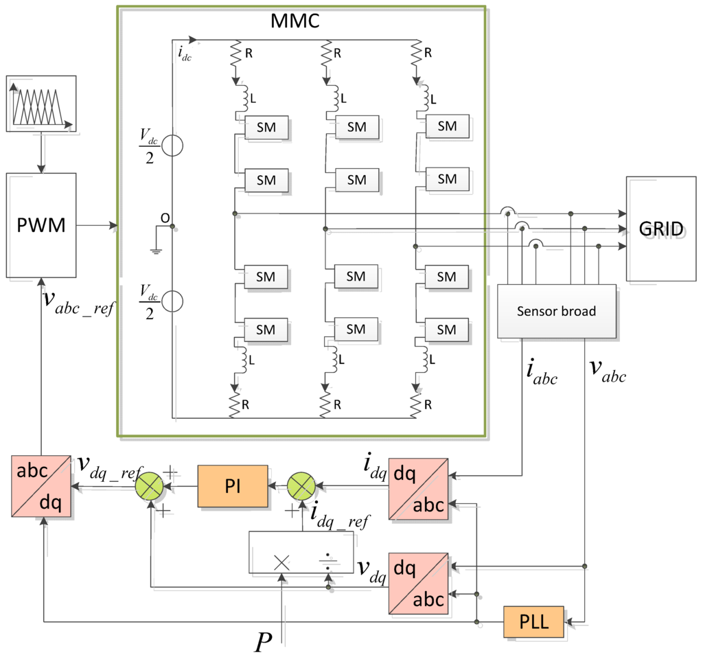
Figure 5.
Block diagram of the grid-side MMC control strategy.
Figure 5.
Block diagram of the grid-side MMC control strategy.

Table 7.
Specifications of the MMC system.
| Parameter | Value | Parameter | Value |
|---|---|---|---|
| Rated active power P | 20 MW | Arm resistor R | 0.05 Ω |
| Rated DC-link voltage Vdc | 60 kV | Number of sub-module N | 12 |
| Rated AC grid voltage Vac | 30 kV | Switching frequency fs | 1.2 kHz |
| Sub-module Capacitor C | 0.8 mF | Fundamental frequency f | 50 Hz |
| Arm inductor L | 5 mH | Modulation index M | 0.9 |
4.1. Normal Operation
The algorithm analysis for a normal MMC operation is conducted. A Phase Shift Carrier Pulse Width Modulation (PSC-PWM) scheme [20] is applied and its output line-to-line voltages vab, vbc, vca are shown in Figure 6. The distortion of the output voltage is caused by the charging and discharging of the capacitors in sub-modules. The output currents ia, ib, ic are displayed in Figure 7. The distortion of the arm currents are caused by the dc components and ac components in the circulating current in the same phase. The capacitor voltages vcp and vcn in the upper arm and in the lower arm in phase a are shown in Figure 8.
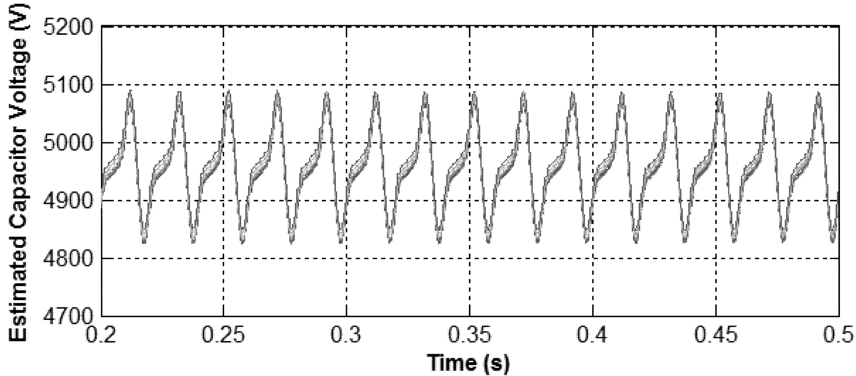
Under the normal condition, all the errors between the measured capacitor voltages and the estimated capacitor voltages present a near-zero value which can be seen from the comparison of measured capacitor voltages in Figure 8 and estimated capacitor voltages in Figure 9.
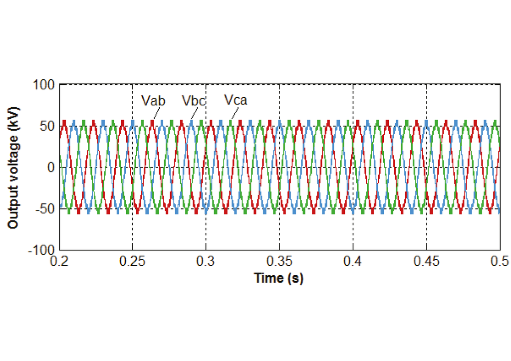
Figure 6.
Output voltages of the grid-side converter with MMC.
Figure 6.
Output voltages of the grid-side converter with MMC.
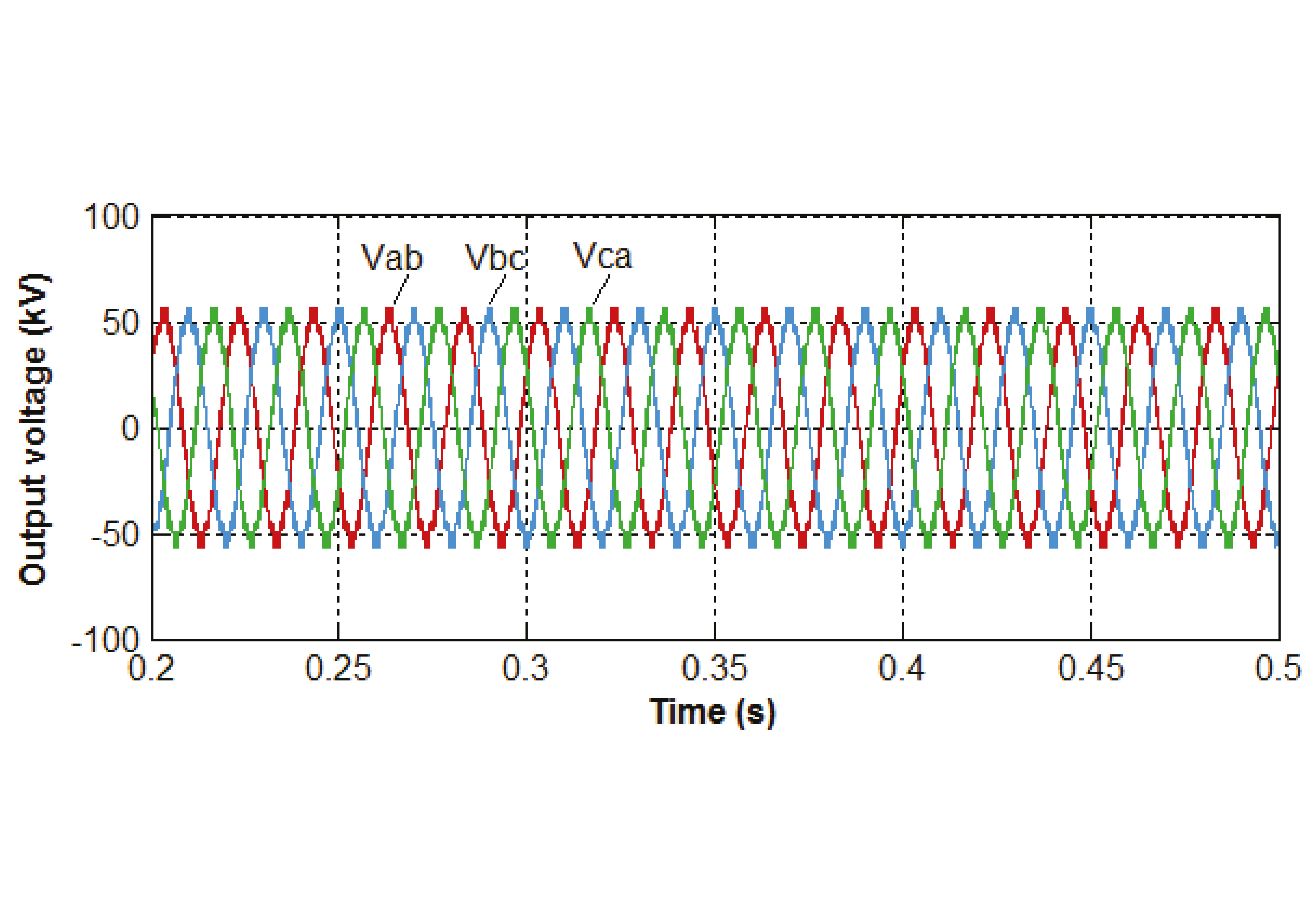
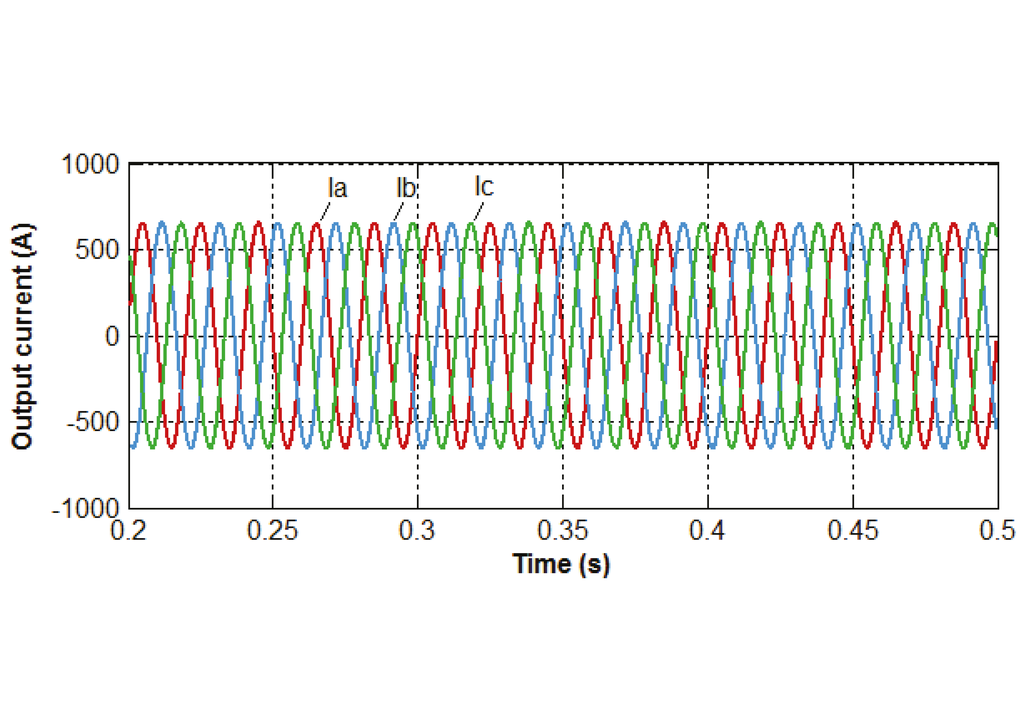
Figure 7.
Output currents of the grid-side converter with MMC.
Figure 7.
Output currents of the grid-side converter with MMC.
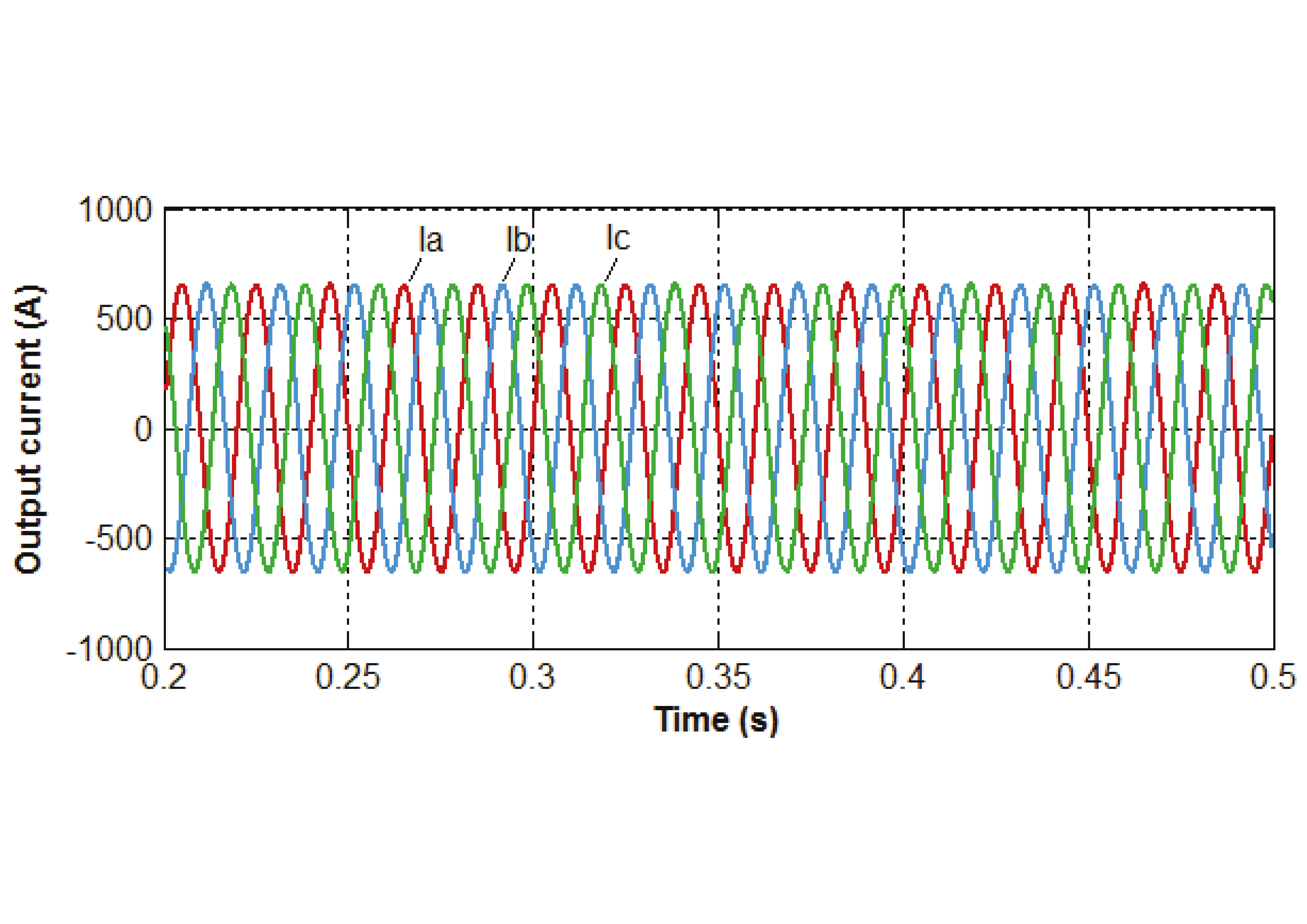

Figure 8.
Measured capacitor voltages in Phase a.
Figure 8.
Measured capacitor voltages in Phase a.
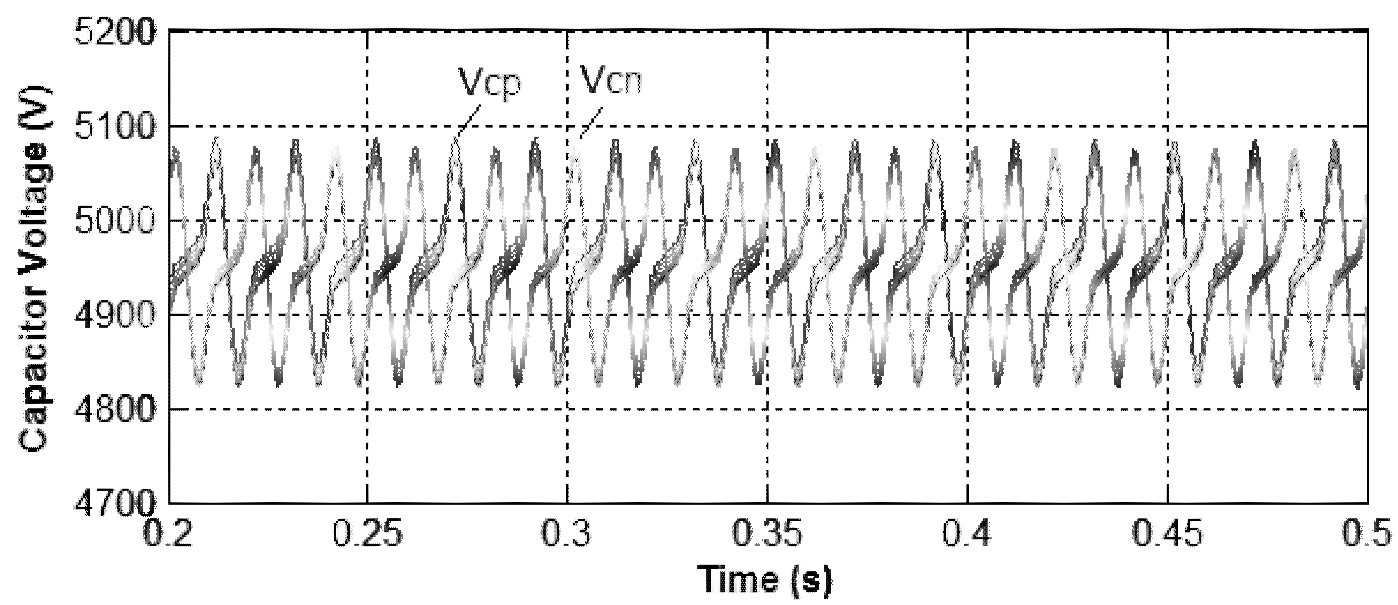

Figure 9.
Estimated capacitor voltages in the upper arm of Phase a.
Figure 9.
Estimated capacitor voltages in the upper arm of Phase a.
4.2. Open-Circuit Fault in T1
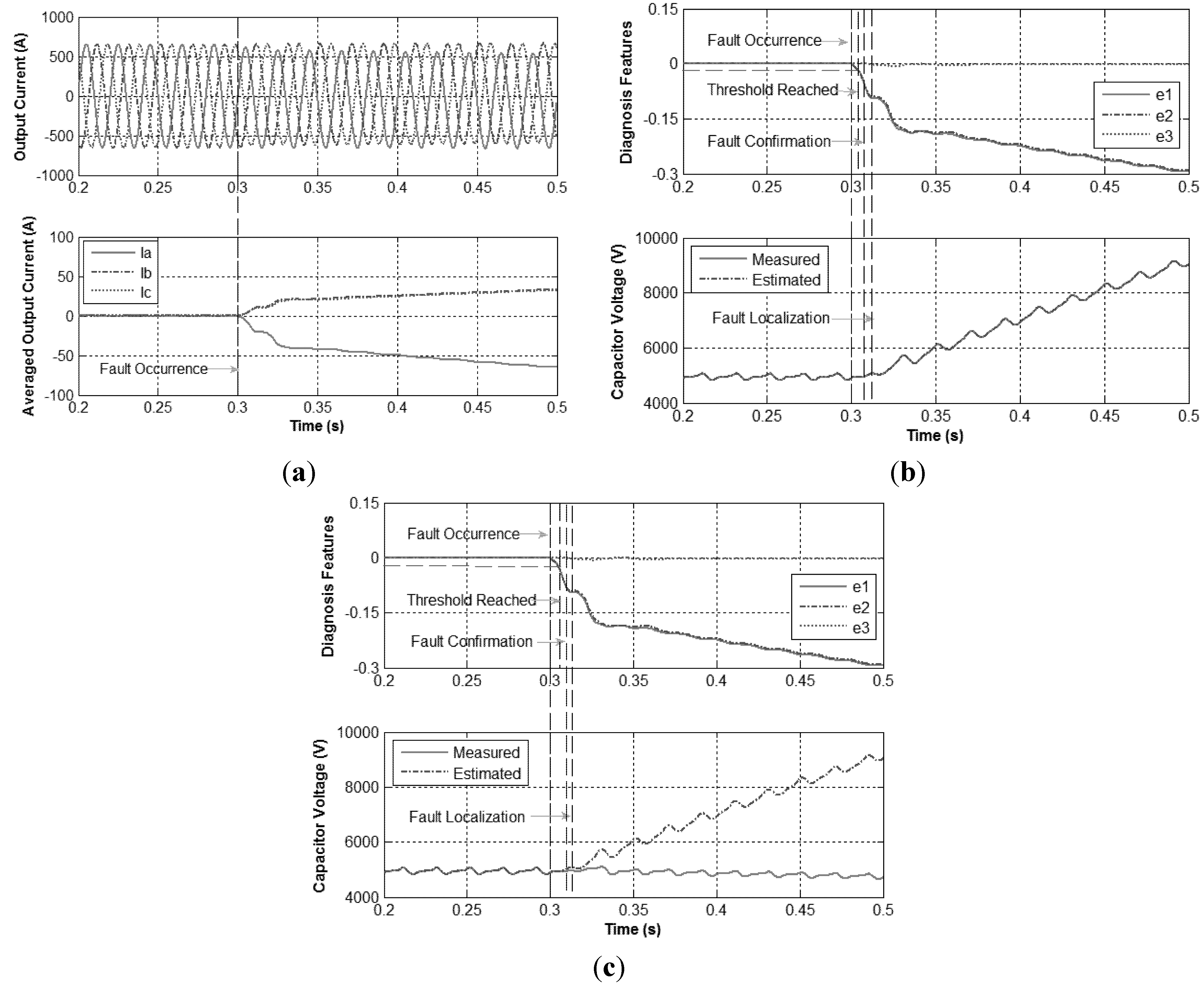
At t = 0.3 s, an open-circuit fault in first module T1 in the upper arm in phase a is introduced and the results are displayed in Figure 10. It can be seen that the waveform of the output currents are normal from 0.3 s to 0.312 s. That’s because the arm current in the upper arm in phase a is positive during 0.3 s to 0.312 s and according to Table 1 the faulty T1 has no effect on the system during this period. After 0.312 s, due to the fact the arm current reaches zero and T1 is turned on and T2 is turned off, the arm current is kept at zero instead of going to negative values until T1 is turned off and T2 is turned on which leads to the increase of the averaged arm current. Regarding the averaged output current values, considering the relationship between the arm currents and the output currents, immediately after 0.312 s, the average value of output current in phase a increases and diverges from others which present similar status. This generates a unique fault signature that matches the conditions defined in Table 5, detecting in this way an open-circuit fault in T1 in phase a of MMC after the fault signature lasts for 500 steps (2 μs per step).


Figure 10.
Open-circuit fault in T1 under 20MW. (a) Output current and their averaged values; (b) Diagnosis features and capacitor voltages in SM1; (c) Diagnosis features and capacitor voltages in SM2.
Figure 10.
Open-circuit fault in T1 under 20MW. (a) Output current and their averaged values; (b) Diagnosis features and capacitor voltages in SM1; (c) Diagnosis features and capacitor voltages in SM2.
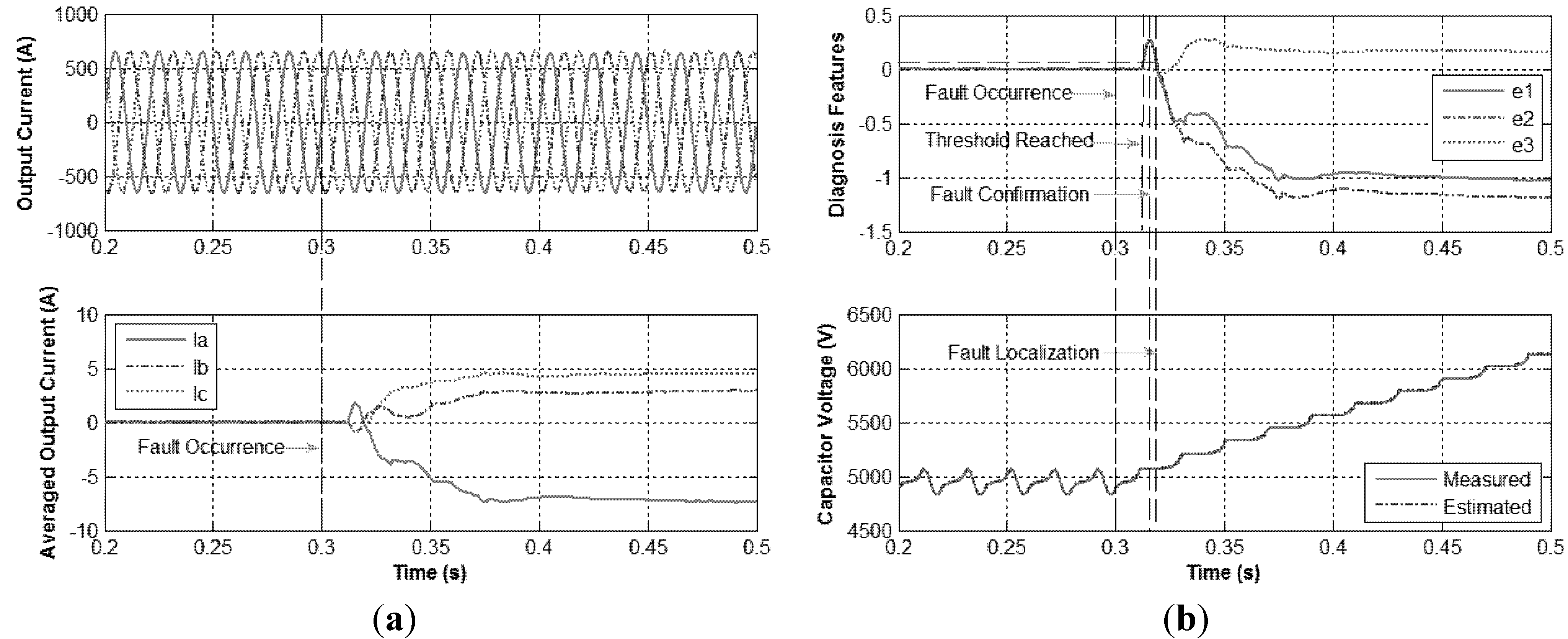
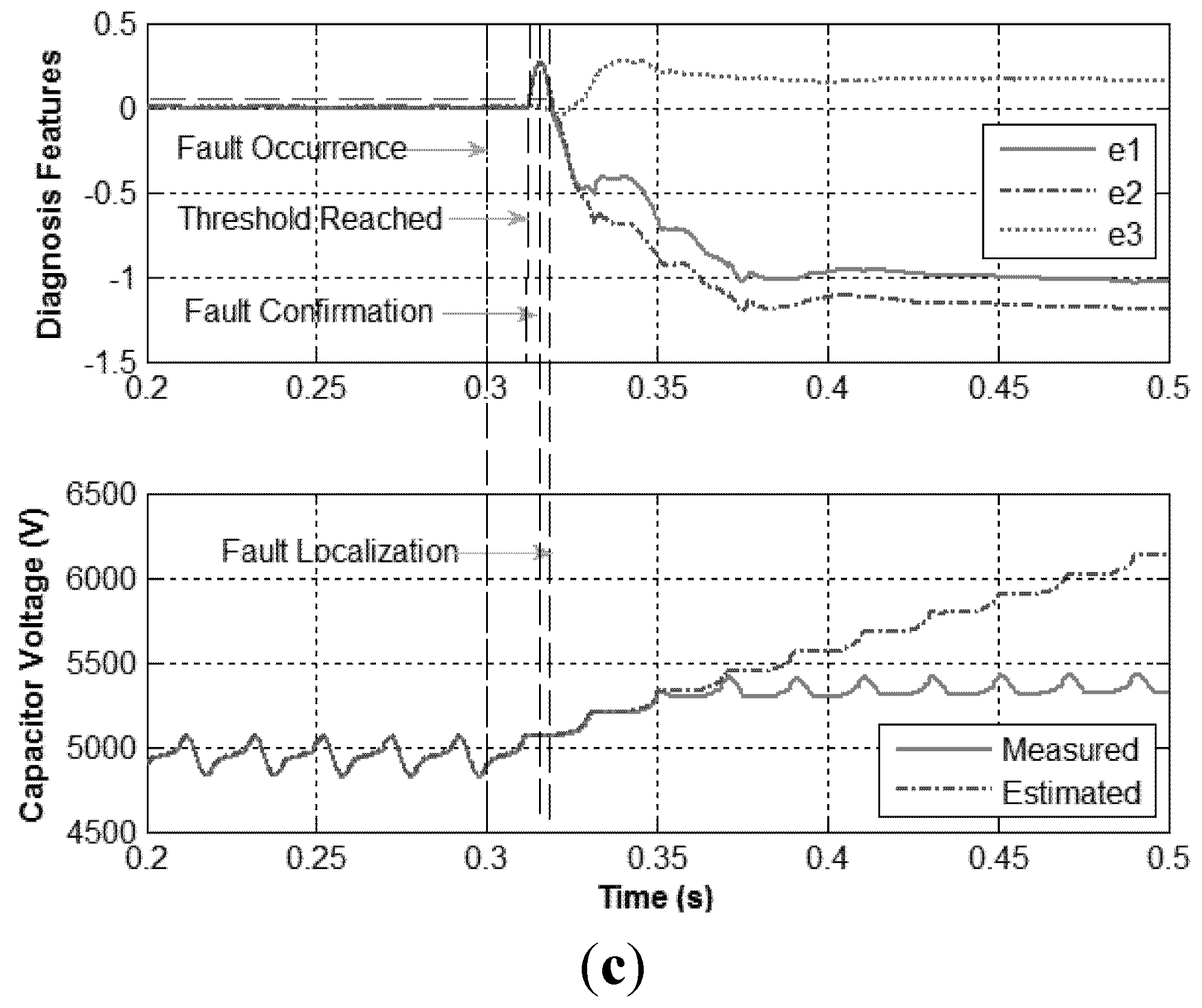
Once the faulty phase and the fault type are detected, the corresponding observer, illustrated by Equations (18)–(21), is immediately adjusted to Mode 2 to estimate the capacitor voltages for all the capacitors in the detected faulty phase. By comparing the measured capacitor voltages with the corresponding estimated capacitor voltages, the faulty module can be identified. For the first capacitor in the upper arm of phase a, the error between the measured capacitor voltage and the estimated capacitor voltage is near-zero value as shown in Figure 10b. However, as shown in Figure 10c, for the second module in the faulty arm, the error between the measured capacitor voltage and the estimated capacitor voltage is much bigger. Therefore, by exclusion, the algorithm localizes the T1 in the first module in the upper arm of phase a as the faulty device.
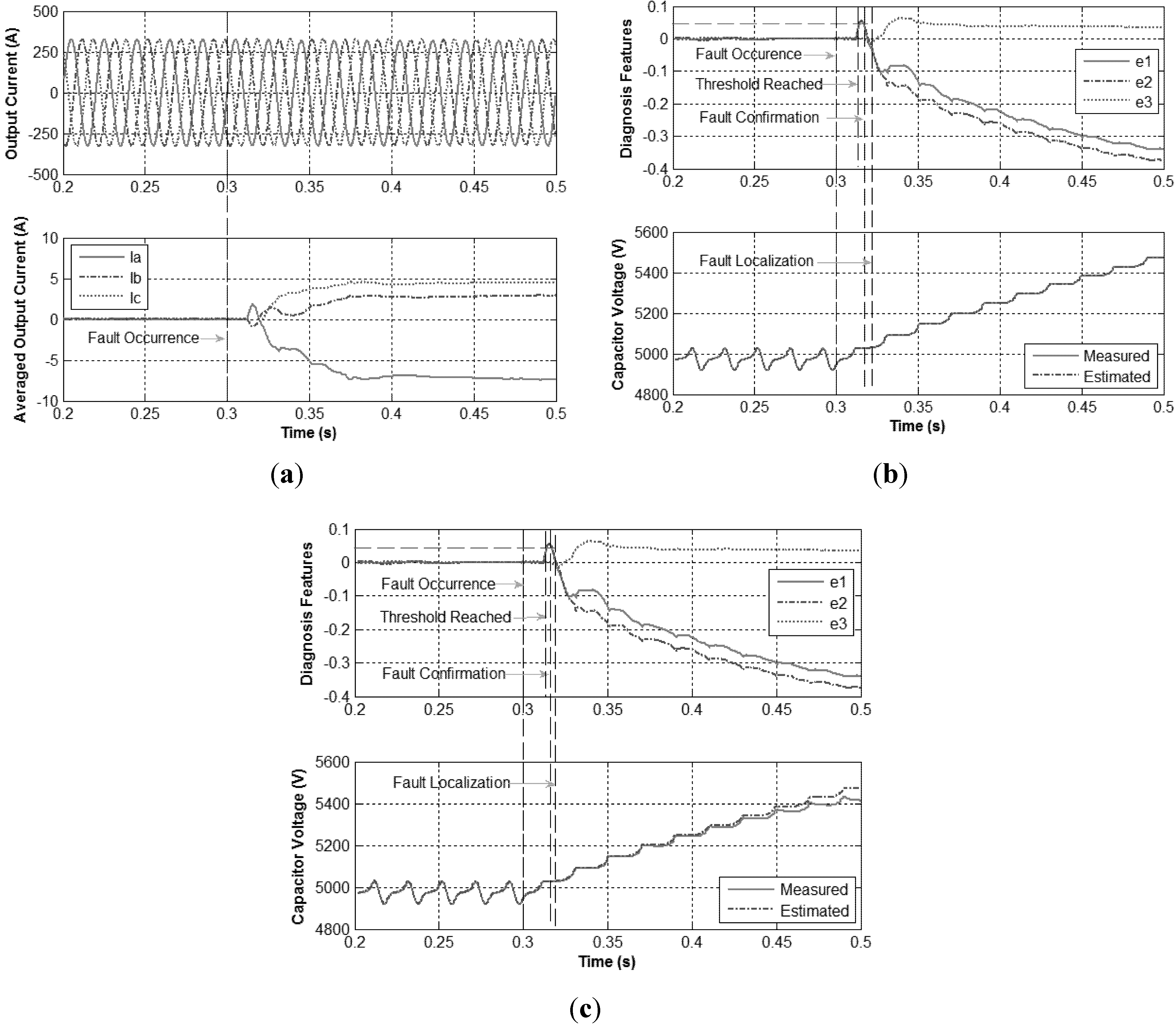
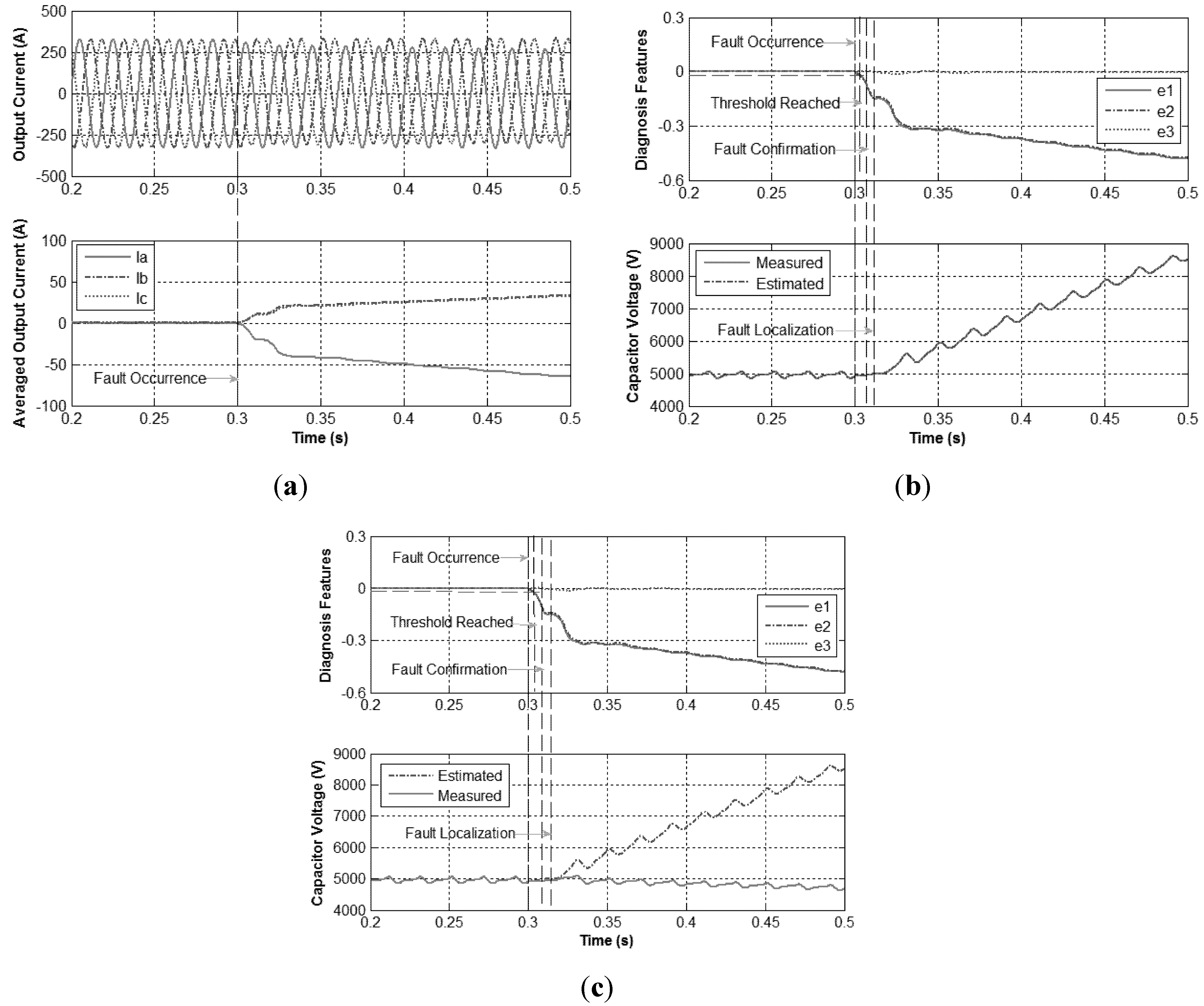
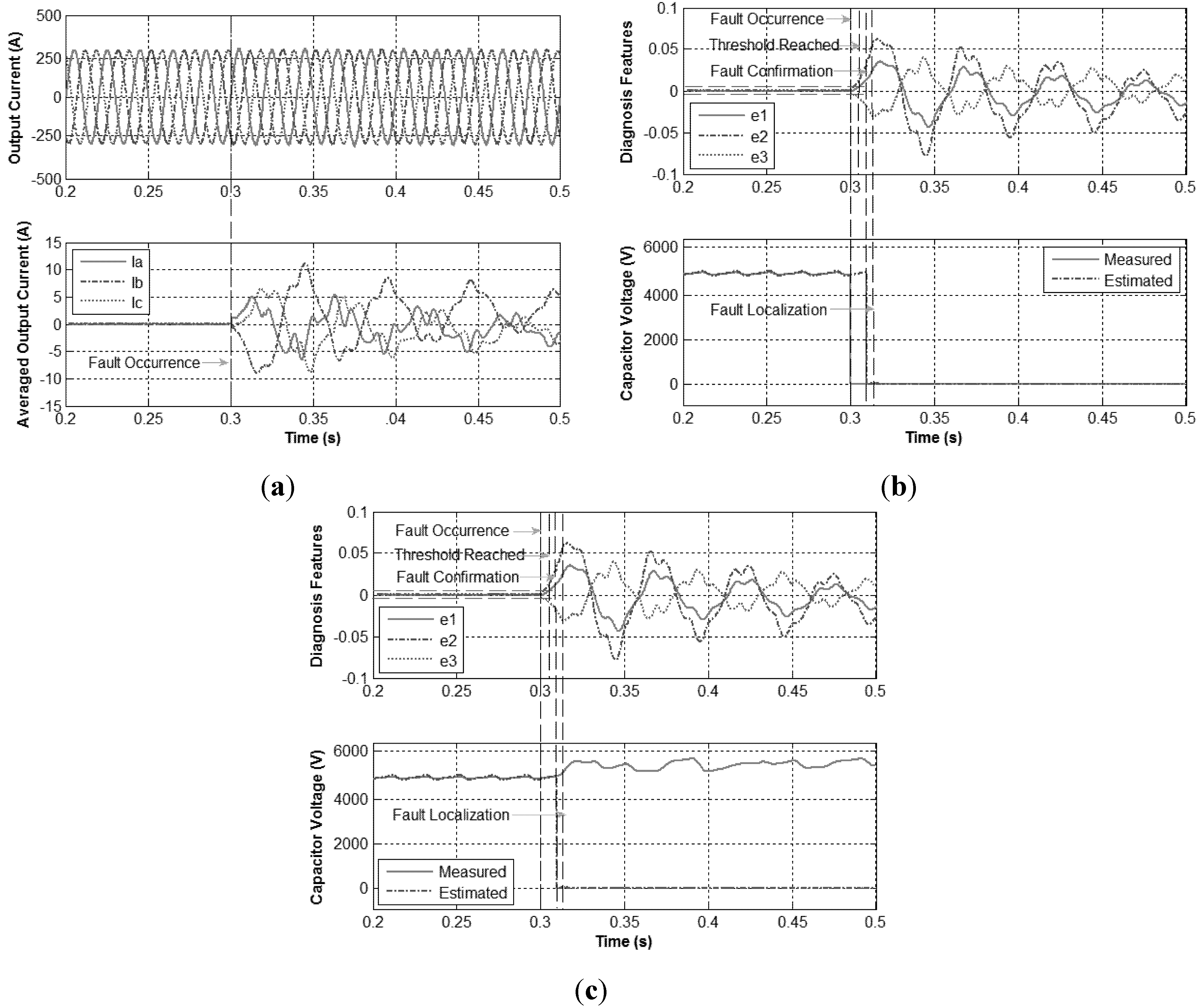
In order to evaluate the algorithm performance for different operating conditions, the equivalent time-domain waveforms of the output currents and the three diagnostic variables for 10 MW transmission power are presented in Figure 11.
In a similar way to the previous case, under normal operating conditions, the diagnostic variables are approximately zero. As shown in Figure 11a, when the open-circuit fault in T1 happens at 0.3 s, two of the diagnosis variables will be almost the same and the remaining one would be near-zero. According to the comparison between the variation tendency of the three diagnosis variables and Table 5, the phase
is detected as the faulty phase and the fault type is an open-circuit fault in T1.
Then comparing the measured capacitor voltages and the corresponding estimated capacitor voltages obtained by using the observer under Mode 2 in the faulty phase the faulty module can be identified if the error between them is zero. As shown in Figure 11b,c, the error in the first module in the faulty phase is zero and in the second module is non-zero. As a consequence, the faulty module is the first module in phase a.

Figure 11.
Open-circuit fault in T1 under 10MW. (a) Output current and their averaged values; (b) Diagnosis features and capacitor voltages in SM1; (c) Diagnosis features and capacitor voltages in SM2.
Figure 11.
Open-circuit fault in T1 under 10MW. (a) Output current and their averaged values; (b) Diagnosis features and capacitor voltages in SM1; (c) Diagnosis features and capacitor voltages in SM2.
What should be noticed is that, the chosen study case is almost the worst case which takes the longest detection time due to from 0.3 s to 0.312 s the arm current is positive in the upper arm in phase a and the faulty T1 doesn’t affect the system operation during this period. If the corresponding arm current is negative when the fault happens, the detection time will be much shorter than this.
4.3. Open-Circuit Fault in T2
Similarly, at t = 0.3 s, an open-circuit fault in first module T2 in the upper arm in phase a is introduced and the results are displayed in Figure 12. It can be seen that the waveform of the output current in phase a changes after 0.3 s and the average value of output current in phase
also, immediately after the fault occurrence, diverges from others which present almost the same trend. The errors among the three averaged output currents trend to match the predefined conditions as listed in Table 5. Hence, the faulty phase and the fault type (open-circuit fault in T2) are detected.

Figure 12.
Open-circuit fault in T2 under 20MW. (a) Output current and their averaged values; (b) Diagnosis features and capacitor voltages in SM1; (c) Diagnosis features and capacitor voltages in SM2.
Figure 12.
Open-circuit fault in T2 under 20MW. (a) Output current and their averaged values; (b) Diagnosis features and capacitor voltages in SM1; (c) Diagnosis features and capacitor voltages in SM2.
Then the corresponding observer is immediately adjusted to Mode 3 to estimate the capacitor voltages for all the capacitors in the detected faulty phase. When the error between the measured capacitor voltage and the estimated capacitor voltage is near-zero value as shown in Figure 12b, the faulty module can be identified and when the error is non-zero, the corresponding module is in normal operation as shown in Figure 12c. Therefore, the T2 in the first module in the upper arm of phase a is recognized as the faulty device.
When the open-circuit fault in T2 happens at 0.3 s under 10 MW transmission power, the changes of the three diagnosis variables are the same as shown in Table 5, as illustrated in Figure 13a. Then the faulty phase and the fault type can be detected and the identification algorithm is triggered. Then the faulty module can be identified as the first module in the faulty phase by observing the estimated error under Mode 3 observer in Figure 13b,c.

Figure 13.
Open-circuit fault in T2 under 10MW. (a) Output current and their averaged values; (b) Diagnosis features and capacitor voltages in SM1; (c) Diagnosis features and capacitor voltages in SM2.
Figure 13.
Open-circuit fault in T2 under 10MW. (a) Output current and their averaged values; (b) Diagnosis features and capacitor voltages in SM1; (c) Diagnosis features and capacitor voltages in SM2.
4.4. Short-Circuit Fault in T1 or T2
Regarding now the algorithm analysis for the occurrence of IGBT short-circuit faults, Figure 14 presents the time-domain waveforms of the three phase currents and the three diagnostic variables for a 20 MW transmission power, with a short-circuit fault in T1.
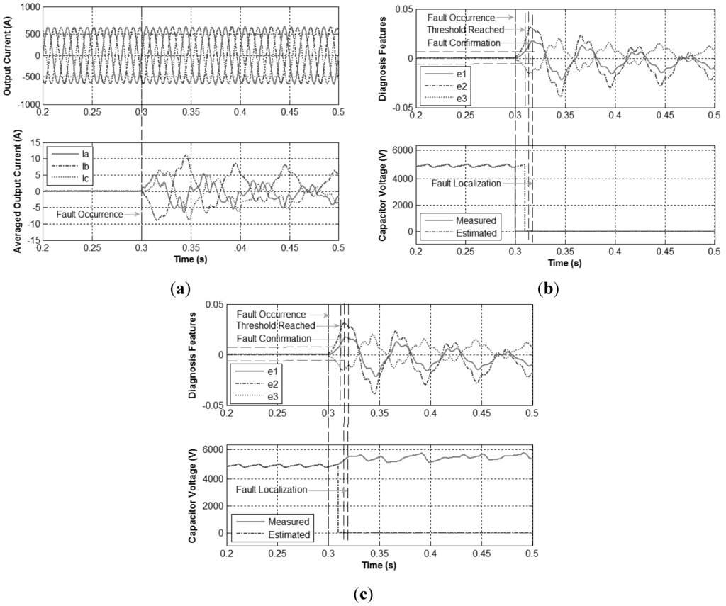
Figure 14.
Short-circuit fault in T1 or T2 under 20 MW. (a) Output current and their averaged values; (b) Diagnosis features and capacitor voltages in SM1; (c) Diagnosis features and capacitor voltages in SM2.
Figure 14.
Short-circuit fault in T1 or T2 under 20 MW. (a) Output current and their averaged values; (b) Diagnosis features and capacitor voltages in SM1; (c) Diagnosis features and capacitor voltages in SM2.

In a similar way to the previous cases, under normal operating conditions, all the three diagnostic variables are zero. Then, at the instant t = 0.3 s, a short-circuit fault in T1 is introduced. As a consequence, it can be observed that, instead of being regulated to zero, because of this fault, the currents become considerably unbalanced. On the other hand, immediately after the fault occurrence, the diagnostic variables e1, e2, and e3 are no longer zero, crossing the threshold value. Considering this, a specific fault signature is also generated, which fulfills the conditions shown in Table 5 for a short-circuit fault in phase a.
Once the diagnostic algorithm detects this fault, the provided information is then used to trigger the observer into mode 4 to estimate the capacitor voltages in the faulty phase. The faulty module can be identified when the error is zero, while the corresponding module is in normal operation if the error is non-zero, as shown in Figure 14b,c. Therefore, the T1 in the first module in the upper arm of phase a is recognized as the faulty device.
With the aim to evaluate the algorithm performance under a short-circuit fault for other mechanical operating conditions, the equivalent time-domain waveforms of the output currents and the six diagnostic variables for 10 MW transmission power is presented in Figure 15.
Under normal operating conditions, it is also clearly seen that all the diagnostic variables present a zero value. At the instant t = 0.3 s, a short-circuit fault in T1 is introduced. It can be seen that, after this moment, the averaged output currents fluctuate, together with the diagnostic variables e1, e2, and e3. When these three variables reach the defined threshold, a unique fault signature is generated that also matches the conditions in Table 5, detecting a short-circuit fault in T1 in phase a.
Since the faults happened in other modules share the same principle as analyzed previously, only open-circuits and short-circuit faults in T1 and T2 in the first module for phase a were analyzed. However, additional tests were also successfully carried out for the other modules and the other phases, proving the effectiveness of the proposed fault identification algorithm.
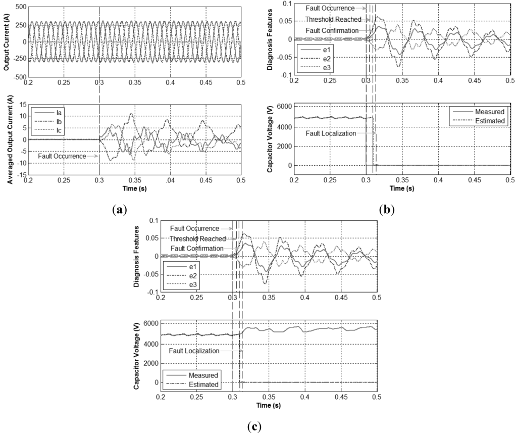
Figure 15.
Short-circuit fault in T1 or T2 under 10 MW. (a) Output current and their averaged values; (b) Diagnosis features and capacitor voltages in SM1; (c) Diagnosis features and capacitor voltages in SM2.
Figure 15.
Short-circuit fault in T1 or T2 under 10 MW. (a) Output current and their averaged values; (b) Diagnosis features and capacitor voltages in SM1; (c) Diagnosis features and capacitor voltages in SM2.
5. Conclusions
A new algorithm for real-time diagnostics of power switch open-circuit and short-circuit faults in MMC has been proposed in this paper. The technique just uses as inputs variables that are already available from the main control system. This means that it avoids the use of extra sensors or electric devices and the subsequent increase of the system complexity and costs.
The obtained results allow concluding that, in opposition to other existing methods, owing to the use of normalized quantities, the algorithm behavior does not depend either on the transmission power level, or on its load level. Accordingly, universal thresholds can be defined, independently of these issues, which greatly simplifies the method implementation and application to other cases.
The proposed technique can effectively detect IGBT open-circuit faults through an algorithm that provides information on the fault type and the affected phases. Then, a specific localization test is performed according to the fault type, which allows one to identify the faulty power module. Nevertheless, although the algorithm relies on the calculation of average values, a converter fault can be detected in a time interval much smaller than the current fundamental period.
Finally, compared with the existing methods, the developed diagnostic algorithm is relatively simple since it just requires a few and basic mathematical operations. This makes it not computationally demanding, and therefore, it can be easily integrated into the main control system without great effort.
Author Contributions
Hui Liu, Ke Ma and Poh Chiang Loh conceived and designed the study. Hui Liu performed the simulation and wrote the paper, while Ke Ma and Poh Chiang Loh supplied guidance. Hui Liu, Ke Ma, Poh Chiang Loh and Frede Blaabjerg reviewed and edited the manuscript. All authors read and approved the manuscript.
Conflicts of Interest
The authors declare no conflict of interest.
References
- Marquardt, R.; Lesnicar, A.; Hildinger, J. Modulares Stromrichterkonzept für Netzkupplungsanwendung bei hohen Spannungen; ETG-Fachtagung: Bad Nauheim, Germany, 2002. [Google Scholar]
- Westerweller, T.; Friedrich, K.; Armonies, U.; Orini, A.; Parquet, D.; When, S. Trans bay cable—World’s first HVDC system using multilevel voltage-sourced converter. In Proceedings of the CIGRE Session 2010, Paris, France, 22–27 August 2010.
- Xu, J.Z.; Zhao, C.Y.; Liu, W.J.; Guo, C.Y. Accelerated Model of Modular Multilevel Converters in PSCAD/EMTDC. IEEE Trans. Power Deliv. 2013, 28, 129–136. [Google Scholar] [CrossRef]
- Siemens HVDC Project. Available online: http://www.energy.siemens.com/us/en/power-transmission/hvdc/hvdc-plus/references.htm#content=2014%20INELFE%2C%20France-Spain (accessed on 16 April 2015).
- Glinka, M.; Marquardt, R. A New AC/AC-Multilevel Converter Family Applied to a Single-phase Converter. IEEE Trans. Ind. Electron. 2005, 52, 662–669. [Google Scholar] [CrossRef]
- Lesnicar, A.; Marquardt, R. An Innovative Modular Multilevel Converter Topology Suitable for a Wide Power Range. In Proceedings of the IEEE Power Tech Conference, Bologna, Italy, 23–26 June 2003.
- Song, W.; Huang, A. Fault-tolerant design and control strategy for cascaded h-bridge multilevel converter-based statcom. IEEE Trans. Ind. Electron. 2010, 57, 2700–2708. [Google Scholar] [CrossRef]
- Lezana, P.; Aguilera, R.; Rodríguez, J. Fault Detection on Multicell Converter Based on Output Voltage Frequency Analysis. IEEE Trans. Ind. Electron. 2009, 56, 2275–2283. [Google Scholar] [CrossRef]
- Yazdani, A.; Sepahvand, H.; Crow, M.L.; Ferdowsi, M. Fault detection and mitigation in multilevel STATCOMs. IEEE Trans. Ind. Electron. 2011, 58, 1307–1315. [Google Scholar] [CrossRef]
- Shao, S.; Wheeler, P.W.; Clare, J.C.; Watson, A.J. Fault detection for modular multilevel converters based on sliding mode observer, IEEE Trans. Power Electron. 2013, 28, 4867–4872. [Google Scholar] [CrossRef]
- Deng, F.J.; Chen, Z.; Khan, M.R. Fault detection and localization of modular multilevel converter. IEEE Trans. Power Electron. 2015, 30, 2721–2732. [Google Scholar] [CrossRef]
- Liu, H.; Loh, P.C.; Blaabjerg, F. Sub-module Short Circuit Fault Diagnosis in Modular Multilevel Converter based on WT and ANFIS. Electr. Power Compon. Syst. 2015, 43, 1080–1088. [Google Scholar] [CrossRef]
- Khomfoi, S.; Tolbert, L.M. Fault diagnosis and reconfiguration for multilevel inverter drive using AI-based techniques. IEEE Trans. Ind. Electron. 2007, 54, 2954–2968. [Google Scholar] [CrossRef]
- Khomfoi, S.; Tolbert, L.M. Fault diagnosis system for a multilevel inverter using a neural network. IEEE Trans. Ind. Electron. 2007, 22, 1062–1069. [Google Scholar]
- Jiang, W.; Wang, C.; Wang, M. Fault detection and Remedy of Multilevel Inverter based on BP Neural Network. In Proceedings of the Asia-Pacific Power and Energy Engineering Conference (APPEEC), Shanghai, China, 27–29 March 2012; pp. 1–4.
- Sedghi, S.; Dastfan, A.; Ahmadyfard, A. Fault detection of a seven level modular multilevel inverter via voltage histogram and neural network. In Proceedings of the Energy Conversion Congress and Exposition (ECCE), Shilla Jeju, Korea, 30 May–3 June 2011; pp. 1005–1012.
- Krener, A.J.; Xiao, M.Q. Nonlinear observer design in the siegel domain. J. Control Optim. 2002, 41, 932–953. [Google Scholar] [CrossRef]
- Blaabjerg, F.; Teodorescu, R.; Liserre, M. Overview of control and grid synchronization for distributed power generation systems. IEEE Trans. Ind. Electron. 2006, 53, 1398–1409. [Google Scholar] [CrossRef]
- Liu, H.; Loh, P.C.; Ma, K.; Blaabjerg, F. State observer design of modular multilevel converter. In. In Proceedings of the IEEE International Symposiums on Power Electronics for Distributed Generation Systems (PEDG), Aachen, Germany, 22–25 June 2015; pp. 413–418.
- Blaabjerg, F.; Liserre, M.; Ma, K. Power electronics converters for wind turbine systems. IEEE Trans. Ind. Appl. 2011, 48, 708–719. [Google Scholar] [CrossRef]
© 2015 by the authors; licensee MDPI, Basel, Switzerland. This article is an open access article distributed under the terms and conditions of the Creative Commons Attribution license (http://creativecommons.org/licenses/by/4.0/).