1. Introduction
Fuel cells are key elements for building a competitive, secure and sustainable clean energy economy. Hydrogen gas is a zero-carbon fuel that can be produced from renewable sources and fuel cells convert directly its chemical energy into electricity. The broad range of benefits to the environment, economy and nation’s energy security that fuel cells can offer include reduced oil consumption, reduced greenhouse gas emissions, reduced pollution, highly efficient energy conversion and highly reliable grid support. For end-users, fuel cells bring additional advantages including quiet operation, low maintenance needs and reliable operation. The target set by the U.S. Department of Energy (DOE) to reduce the greenhouse gas emissions 80% by 2050 [
1] and to eliminate the dependence on imported fuel requires the widespread use of hydrogen and fuel cells in all energy sectors—industrial, commercial, residential and transportation.
Compared to other types of fuel cells, Polymer Electrolyte Membrane Fuel Cells (PEMFCs) offer the advantages of delivering higher gravimetric and volumetric power densities and of operating at lower temperatures which results in a quick start up time and less wear on the system components. These advantages make PEMFCs particularly suitable for transportation and stationary applications. The global market value for PEMFCs in 2012 was $486 Million and expected to reach $1.24 Billion by the year 2017.
As identified by DOE, the number one challenge that remains to be resolved on the road to a hydrogen economy is the cost of manufacturing fuel cells [
1]. In today’s fuel cell industry, fuel cell stacks are assembled manually in a lengthy process involving a repetitive work cycle in which human errors are common. It is currently common to take as long as a full day to assemble and leak-test a single stack. To be commercially viable, stack assembly must be accomplished in minutes, not hours [
2].
In the early stages of fuel cell prototype development, fuel cell stacks may be assembled manually, but the introduction of automated assembly processes become economically justifiable once the production quantity increases. For fuel cell stacks consisting of large number of cells, the objective and subjective effects on the worker and on the product quality which are related to the monotony of repetitive work cycles characteristic to fuel cell assembly, further justifies the adoption of automated assembly processes. An automated fuel cell assembly process is justified as well when integrated into larger automation lines in which the fuel cell components are also produced using automatic technologies.
Previous efforts in demonstrating automatic assembly lines for fuel cells validate the conclusion that the automatic assembly process represents a solution to reduce their manufacturing cost. There are specific technical challenges related to an automated fuel cell assembly process. Probably the most significant one represents the difficulty to precisely align the fuel cell components in the stack when the operation is performed by a robot arm that has inherent limitations in accuracy and repeatability and a lack of compliance (flexibility in robot joints). Misalignment of the fuel cell components generates overboard leaks of the reactant gasses during the fuel cell operation. The challenge of precisely aligning the fuel cell components in the stack increases with the stack length which is determined by its number of cells. To avoid component misalignment, it is a common practice in a manual fuel cell assembly process to use steel alignment pins inserted in one endplate and positioning holes in the fuel cell components that are used to guide the components along the pins. However, in an automated assembly process performed by a robotic arm with inherent limited accuracy and repeatability, with a lack of compliance and with alignment pins that have a certain tolerance to position and straightness, this approach will most often result in jamming the components during their insertion along the alignment pins. A second challenge in an automated assembly process is related to the variety of fuel cell components that need to be handled by the robot arms. These components include thin, flexible membrane electrode assemblies (MEAs), rubber gaskets, graphite paper, graphite bipolar plates, copper current collector plates and end-plates. This has led in the past to expensive automated assembly workcells consisting of a number of different robots, each dedicated for handling a particular fuel cell component. A major barrier in the way to successfully demonstrate in the past an automated fuel cell assembly technology consisted in an insufficient integration of the fuel cell design process with the design of the robot assembly line. There have been attempts [
3] to demonstrate a robotic fuel cell assembly process using fuel cell components that were not designed for an automated assembly. For the automated assembly line to be successfully demonstrated, it has been shown [
4] that the robot end-effector as well as the fuel cell components must include design features that allow an accurate engagement and component alignment during pick up and release operations, as well as to compensate for the robot limited accuracy, repeatability and lack of compliance.
The Flexible Manufacturing Center and the Center for Automation Technologies and Systems at Rensselaer Polytechnic Institute have researched the robotic assembly of fuel cells [
3,
5] in workcells consisting of multiple robots but with limited success in demonstrating its feasibility. ZSW (Centre for Hydrogen and Solar Technology) and the University of Applied Sciences in Ulm, Germany [
6] as well as ZBT (Zentrum fűr Brennstoffzellentechnik) in Duisburg, Germany [
7] successfully demonstrated lengthy automatic assembly processes for single cells which involve the application of liquid rubber sealant to address the overboard gas reactant leaks. The workcell consists of seven sections connected by conveyors, including a section for curing the rubber sealant. The disadvantage of the demonstrated technologies is that they are limited to assembly of single cells in very lengthy processes involving expensive automation lines. ZSW also successfully demonstrated a simple and rapid automated assembly line for multi-cell PEMFC stacks using a KUKA robot [
8]. The end-effector is capable of handling a variety of components and aligning them in the stack. The end-effector does not appear to possess compliance and its arrangement relative to the robot wrist assembly does not allow it to assemble longer stacks. The alignment pins in the demonstrated technology are metallic and need to be removed after assembly, which may induce component misalignment during removal process.
We have recently successfully demonstrated an automated assembly process for PEMFS stacks [
4,
9] using an end-effector [
10] with passive compliance and fuel cell components with design features that allowed their accurate alignment in the stack. In this paper, we present our second generation of end-effector and robot workcell as well as the fuel cell design features that enabled an even higher productivity of the automated assembly process and the capability of the robot to assemble larger scale fuel cell stacks.
2. Approach
2.1. End-Effector
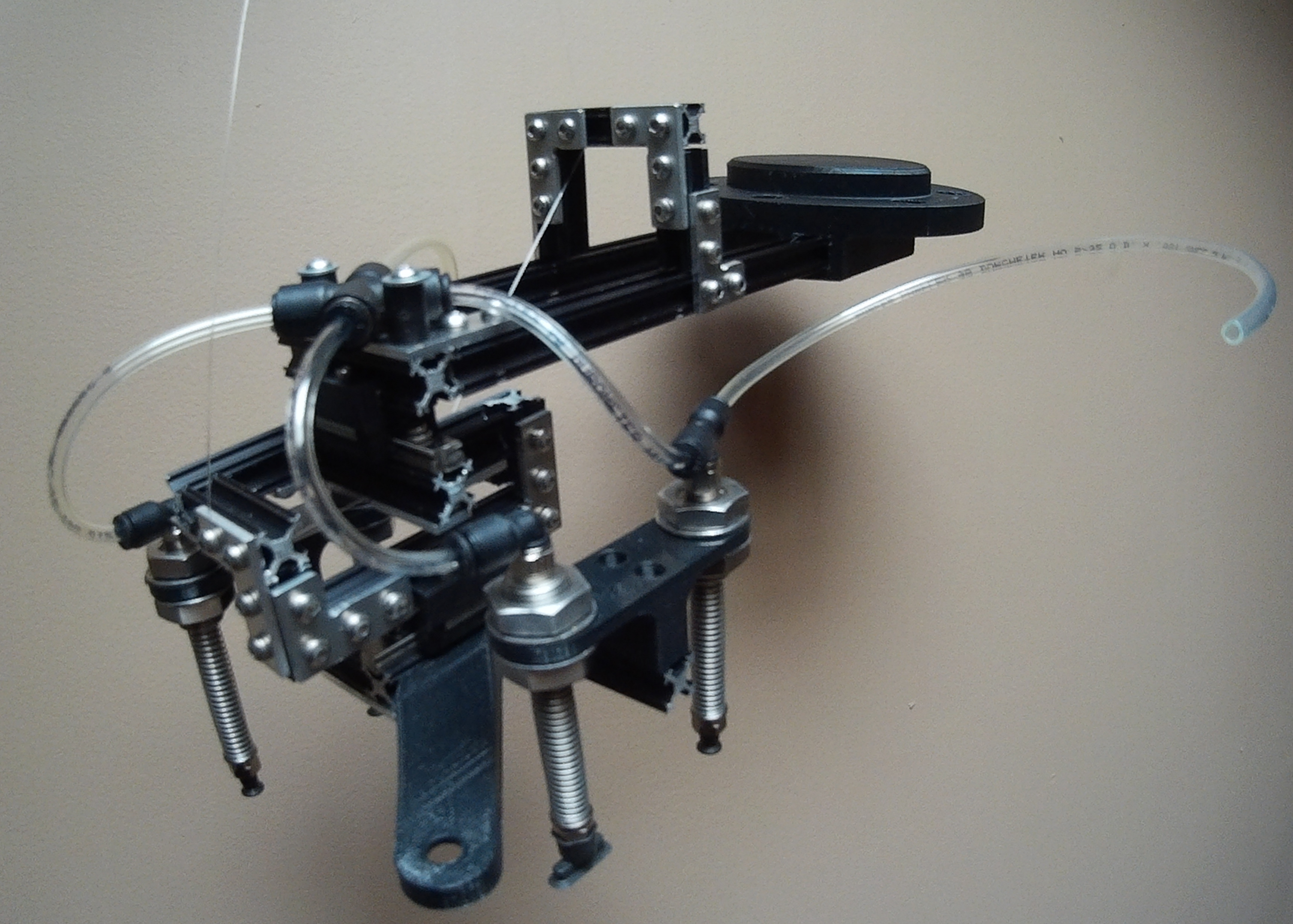
The second generation end-effector was designed to increase the manufacturing productivity and the robot’s capability to assemble fuel cell stacks consisting of any number of cells, while maintaining its capability of aligning the fuel cell components in the stack without jamming them and maintaining a low manufacturing cost. The end effector was built from MicroRax miniature aluminum extrusion T-slot framing (Twintec, Inc. in Auburn, WA, USA) and components produced by 3D printing (see
Figure 1 and
Figure 2). It consists of three subassemblies connected to each other by two miniature linear blocks and rails (Anaheim Automation, Inc. in Anaheim, CA, USA). The linear block and rails are oriented at 90 degrees relative to each other and allow a relative motion along X and Y axes between the lower subassembly which grasps the fuel cell components and the top subassembly which attaches the end-effector to the robot wrist assembly. Each linear block and rail mechanism has stoppers which delimits the block’s travel to about 3 mm along the rail. These in-plane degrees of freedom offer the end-effector a reliable passive compliance capability that compensates for the robot’s limitations in accuracy, repeatability and lack of joint flexibility. Furthermore, they allow the end-effector to slide the positioning holes of the fuel cell components along the alignment pins when the latter have a certain tolerance to position and straightness. This compliance system along with the conical tip of the alignment pins (see
Section 2.2) may compensate for misalignments as large as a few millimeters, which are much larger than the usual limitations in a robot’s accuracy and repeatability.
Figure 1.
The end-effector attached to the robot wrist-assembly.
Figure 1.
The end-effector attached to the robot wrist-assembly.
Figure 2.
Partially exploded view of the end-effector depicting its main subassemblies. The tubing connecting the vacuum cups through the suspension mechanisms to the vacuum pump is not represented.
Figure 2.
Partially exploded view of the end-effector depicting its main subassemblies. The tubing connecting the vacuum cups through the suspension mechanisms to the vacuum pump is not represented.
The lower subassembly of the end-effector (
Figure 1) has the role to pick up and release the fuel cell components and to align them along the alignment pins on one fuel cell end-plate. It supports four level compensators (SLSA-120NR from Anver, in Hudson, MA, USA) provided with vacuum cups and suspension mechanisms that are used to provide a soft touch and to reduce the machine need for indexing when picking up and releasing fuel cell components in the stack. The four vacuum cups are pneumatically connected through tubing and fittings mounted on the level compensators to a miniature vacuum pump (JV09CET from Anver). A winglet with two positioning holes (Ø.27″ diameter) is also attached to the lower subassembly such that the holes align with the positioning holes in the fuel cell components during pickup and release operations.
The intermediate subassembly has only the role of interconnecting the lower and the top subassemblies though the miniature linear blocks and rails and to provide passive compliance to the end-effector.
The top subassembly connects the end-effector to the robot wrist-assembly and consists of an interface component and aluminum extrusion framing. Unlike previous end-effectors [
4,
8], in this second generation design, the interface component that attaches to the robot wrist-assembly is off-centered relative to the suspension mechanisms and vacuum cups, preventing the fuel cell stack from interfering with the robot wrist-assembly during pick up and release operations when the fuel cell stack consists of a large number of cells. This design enables automated assembly of fuel cell stacks consisting of any large number of cells.
The interface component of the end-effector that attaches it to the robot wrist-assembly, the winglet, the supports for level compensators and the supports for the linear blocks that attaches them to the lower and top subassemblies (see
Figure 2) were manufactured from acrylonitrile butadiene styrene (ABS) using 3D printing. This manufacturing method, along with the use of miniature aluminum extrusion T-slot framing results in an inexpensive end-effector that possesses sufficient mechanical strength required during the assembly of fuel cell stacks. Furthermore, the ease and versatility of interconnecting the aluminum extrusion framing components allows one to adapt the end-effector design to match the design of fuel cell components of any shape and size.
2.2. Fuel Cell Components
The components for a 19-cells PEMFC stack with an active area of 45 cm
2 were designed and manufactured with features that allowed the robot end-effector to grasp, handle and align them in the stack [
4,
10]. The bipolar plates were machined in-house using a Tormach CNC milling machine out of 100 mm × 100 mm × 4 mm graphite plates purchased from TDM LLC. They were designed and machined with a 5-channel serpentine flow field at anode and an interdigitated flow field at cathode and with inlet and outlet manifolds and two Ø.27″ positioning holes for alignment pins along the peripheral area (
Figure 3).
Figure 3.
Bipolar plates used for robotic assembly of the fuel cell stack. The figure shows two positioning holes for centering pins. (a) 5-channel serpentine anode flow field; (b) Interdigitated cathode flow field.
Figure 3.
Bipolar plates used for robotic assembly of the fuel cell stack. The figure shows two positioning holes for centering pins. (a) 5-channel serpentine anode flow field; (b) Interdigitated cathode flow field.
The phosphoric acid (PA)—doped polybenzimidazole (PBI)—based MEAs were purchased from
Advent Technologies without the final cut for inlet and outlet manifolds. The final cut was done using laser cutting (Universal Laser Systems, M300) and feature an identical pattern for the inlet and outlet manifolds and for the positioning holes on the peripheral area as the bipolar plates. The gaskets made of 0.35 mm thick Perfluoroalkoxy (PFA) sheets were purchased from
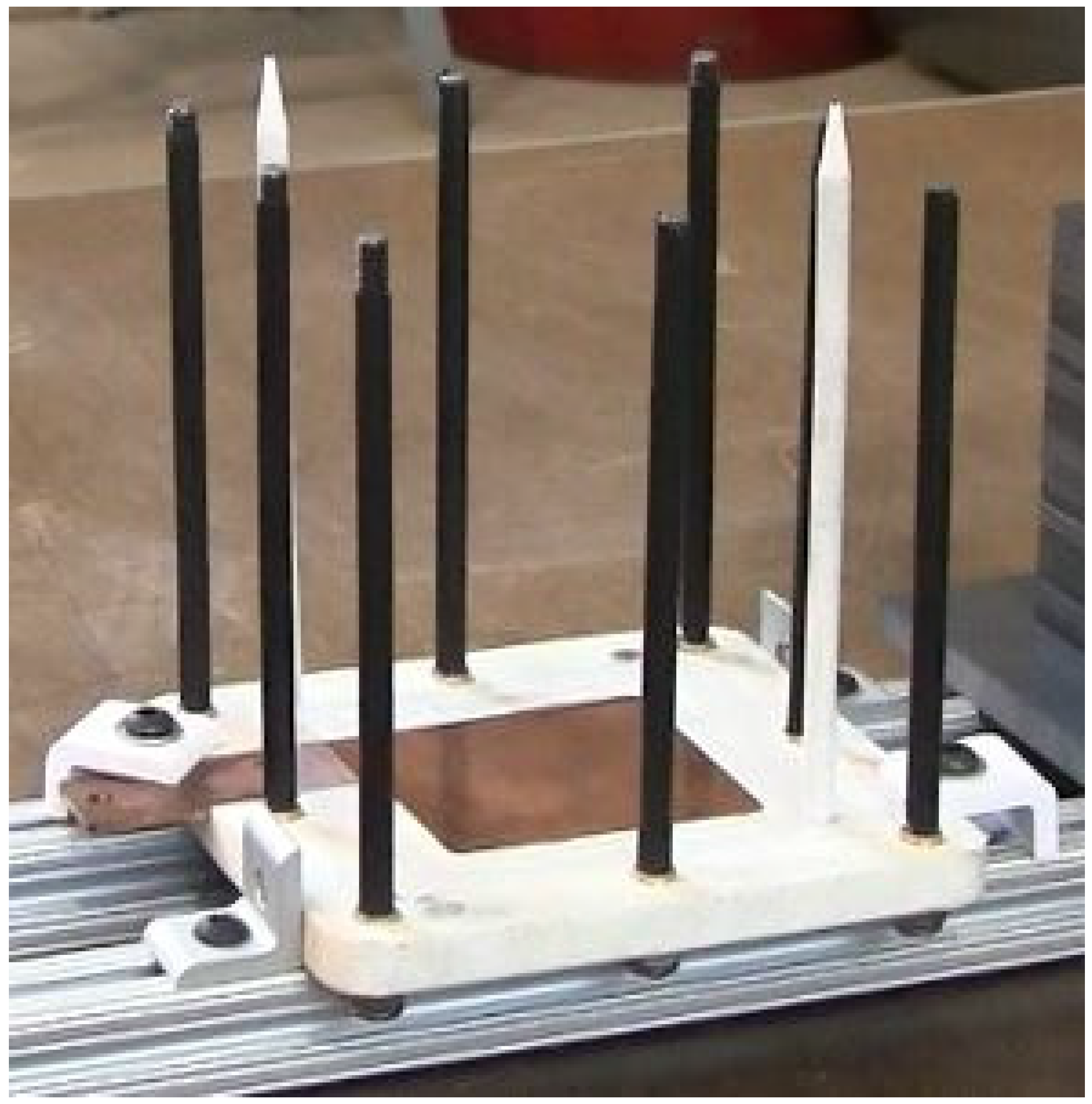
Advent Technologies with an identical pattern for inlet and outlet manifolds and for positioning holes as the MEAs and bipolar plates. The inner opening of the gaskets is on each side 0.02″ wider than the GDLs bonded on each side of the MEA. The endplates were machined in-house out of 0.375″ thick poly(tetra)fluoroethylene (PTFE) plates and feature each a recess for copper current collector plates. One endplate on which the fuel cell components are stacked is provided with two threaded holes on which two alignment pins are permanently mounted (
Figure 4). The alignment pins are made of Ø.25″ diameter PTFE rods and are threaded at the end which is permanently mounted on one endplate while the opposite end is sharpened approx. 30° using a pencil sharpener. The alignment pins were designed with a conical end in order to ease the engagement between the positioning holes on the end-effector and on the fuel cell components and the alignment pins during pick up and release operations. The PTFE material of the alignment pins was selected to reduce the friction with the fuel cell components during assembly and to prevent short circuiting the stack during operation while withstanding the operating temperatures of a High-Temperature PEMFC.
The allowance between the alignment pins (Ø.25″) mounted on the endplate and the positioning holes (Ø.27″) on other fuel cell components and on end-effector permit the fuel cell components to slide easily along the pins and to align within a tolerance of 0.02″, which is smaller or equal to the allowance between the GDLs and the inner opening of the gaskets. This prevents the gaskets from accidentally overlapping the GDLs during the assembly process, which is a major cause of overboard gas leaks during fuel cell operation.
Figure 4.
Endplate located and clamped in the assembly workcell. Two poly(tetra)fluoroethylene (PTFE) alignment pins (white) are permanently mounted on the endplate. The alignment pins feature a conical end which eases the engagement between the positioning holes on the end-effector and fuel cell components and the alignment pins during release operations. There are also eight tie-rods mounted on the endplate which used for compressing the stack. The figure also depicts two locators and two clamps used for positioning the endplate on the workbench.
2.3. Assembly Workcell
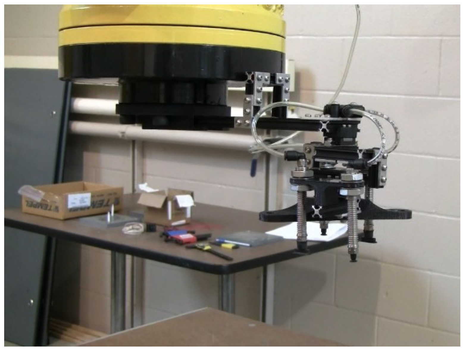
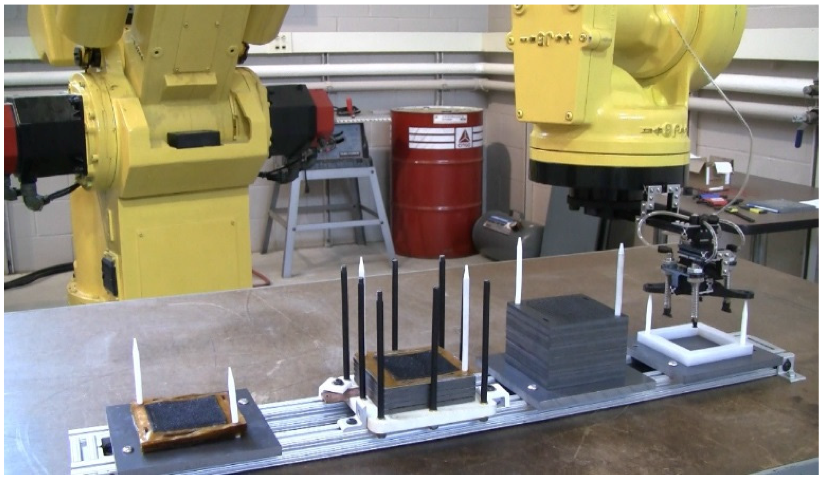
The capability of the end-effector to handle bipolar plates, MEAs and gaskets enabled the design and demonstration of an inexpensive assembly workcell involving a single robot. The second generation workcell for PEMFC stack assembly consists of a Fanuc S 420F robot and a workbench on which three stacks containing bipolar plates, gaskets and MEAs and the endplate with alignment pins on which the fuel cell stack is built are securely mounted (
Figure 5). The three stacks where the fuel cells components are picked from consist of a polyvinyl chloride (PVC) support plate with two PTFE alignment pins each, similar to the alignment pins on the fuel cell endplate. The PVC plates and the fuel cell endplate are mounted on an aluminum extrusion framing attached to the workbench. The PVC plates from where the fuel cells components are picked from are permanently mounted to the frame. Every time a new stack is assembled, a fuel cell endplate is attached to the frame using locators and clamps (see also
Figure 4). The locators allow the new endplate to be mounted every time in the same position.
The bipolar plates on one stack and the MEAs on the second stack are aligned all in the same direction, for example with the anode flow field and the cathode catalyst layer oriented upwards.
Figure 5.
The assembly workcell consisting of one Fanuc S 420F robot and a framing attached to the workbench on which the fuel cell endplate (second from left) and three polyvinyl chloride (PVC) plates from where the membrane electrode assemblies (MEAs) (first from left), the bipolar plates (third) and gaskets (fourth) are picked from are securely mounted. A new fuel cell endplate is placed on the frame every time a new stack is built. The endplate is positioned on the frame using locators and clamps.
2.4. Assembly Process
The robot picks up the fuel cell components and places them on the fuel cell endplate in the following order: bipolar plate, gasket, MEA, gasket, bipolar plate,
etc. During pick up operations (
Figure 6a) the positioning holes on the end-effector engage with the alignment pins on the pickup stack even if the misalignment is as large as a few millimeters, while the compliance system allows the positioning holes to realign with the pins when the end-effector approaches the stack. In this way, the vacuum cups always step on the peripheral area of the fuel cell components in the same position within a tolerance of 0.02″. When the fuel cell components are released on the fuel cell stack (
Figure 6b) the positioning holes on the fuel cell components and on the end-effector align with the alignment pins on the endplate and the components are released always in the same position within a tolerance of 0.02″. This prevents the GDLs from overlapping the gaskets.
Figure 6.
(a) Pick up operation of a bipolar plate; (b) Release operation of MEA.
Figure 6.
(a) Pick up operation of a bipolar plate; (b) Release operation of MEA.
The robot was programmed by leadthrough programming using a teach pendant. The program consists of a subroutine that contains three end-effector positions for each of the pickup stacks and for the fuel cell stack: above the alignment pins, midway between the tips of the alignment pins and the top surface of the stack and the positions where the components are released. As the end-effector approaches the position where the components are released, only the Z-coordinate of the end-effector (the vertical distance from the workbench) modifies, while the X, Y coordinates and the angles about the three coordinate axes remain unchanged. In order to account for indexing the program calculates the Z-coordinate of the top of each stack every time a component is picked or released. The subroutine contains the end-effector positions for a single cell cycle and it is iterated until all the cells in the stack are assembled.
The assembly process was demonstrated with a robot speed of 35 cm/s when the end-effector traveled above the stacks, 7 cm/s during pick up and release of bipolar plates and gaskets and 1.5 cm/s during pick up and release of MEAs. With these parameters, the automated assembly process averages one minute per cell.
To compare the productivity of the present automatic assembly process with a manual assembly process, the fuel cell stack was disassembled and reassembled manually. For a meaningful comparison between the two processes, before the manual assembly, the graphite bipolar plates and the MEAs were pre-arranged in two stacks, all in the same direction, with the anode flow field and the cathode catalyst layer oriented upwards. The manual assembly process lasted about 30 min (an average of about 1.5 min per cell). The delays in the manual operations as compared to the operations performed by the robot were mostly during the insertion of the fuel cell components along the alignment pins, as well as due to periodic breaks necessary for a human operator performing a repetitive work cycle. These delays are expected to increase significantly as the size of the fuel cell stack increases.
A comparison between the robotic assembly process described here and other automatic assembly processes was not easy at the time of preparing this manuscript due to a lack of literature describing successful similar demonstrations. The only similar, successful automated assembly process that we are aware of is the one presented in [
8].
Table 1 below compares the robotic assembly processes demonstrated at Kent State University (KSU) using our first generation end-effector [
9,
10], using the second generation end-effector (the technology presented in this work) and the robotic assembly process shown in [
8].
Table 1.
Productivity and capability of the robotic assembly process presented here (KSU 2
nd Generation) compared to those in references [
8] and [
9,
10].
Table 1.
Productivity and capability of the robotic assembly process presented here (KSU 2nd Generation) compared to those in references [8] and [9,10].
| Robotic Assembly Process | Average time/Cell | Capability to Assemble Long Stacks | Compliance |
|---|
| KSU 1st Generation [9,10] | 120 s | No | Yes |
| KSU 2nd Generation | 60 s | Yes | Yes |
| Reference [8] | 80 s (see Note) | No | N/A |
3. Conclusions
In this paper we present the technology demonstrated at Kent State University for robotic assembly of PEMFC stacks. The second generation end-effector and robot workcell presented here increase the productivity of the automated assembly process and the capability of the robot to assemble larger scale fuel cell stacks. The end-effector possesses a passive compliance system consisting of two linear block and rail mechanisms that compensate for the robot’s inherent limitations in accuracy, repeatability and lack of joint flexibility. Furthermore, they allow the end-effector to slide the positioning holes of the fuel cell components along the alignment pins without jamming them during the assembly process when the latter have a certain tolerance to position and straightness. A system consisting of vacuum cups attached to a vacuum pump through level compensating mechanisms allow the end-effector to grasp and handle a variety of fuel cell components including MEAs, gaskets and bipolar plates. This later feature enables the design and manufacture of a robot workcell for PEMFC automated assembly consisting of a single robot. The fuel cell components used in this demonstration were designed and built with features that allowed their automated assembly in the stack. They consist in flexible, electrically non-conductive alignment pins permanently mounted on one fuel cell endplate and bipolar plates, MEAs and gaskets with positioning holes. The allowance between the alignment pins and the positioning holes on the fuel cell components permit them to align within a tolerance of 0.02″, which is smaller or equal to the allowance between the GDLs and the inner opening of the gaskets. This prevents the gaskets from accidentally overlapping the GDLs during the assembly process, which is the major cause of overboard gas leaks during fuel cell operation. The advantage of the technology presented here consists in its low cost, its simplicity, in its capability of rapidly assembling fuel cell stacks containing a large number of cells and in its capability of accurately aligning the fuel cell components in the stack.


