Abstract
Permanent magnet linear motors (PMLMs) with double-layer concentrated windings generally show significant cogging forces due to the introduction of auxiliary teeth for eliminating the end-effect induced phase unbalance, even when the fractional-slot technology is applied. This paper presents a novel approach to reduce the cogging force by adjusting the armature core dimensions in fractional-slot PMLMs with double-layer concentrated windings, together with magnet skewing. It is shown that the proposed technique is capable of reducing the cogging force of the motor in an effective way, with the peak value minimized to less than 0.4% of the rated thrust force in the case study. Such a technique can also be applicable to other linear motors with appropriate changes.
1. Introduction
Fractional-slot permanent magnet linear motors (PMLMs) are a key enabling technology in modern applications for their favorable features of high force-density, improved efficiency, and excellent dynamic performance [1,2,3,4,5]. However, the interactions of permanent magnets (PM) with finite-length cores and slotted armatures result in cogging forces, which would deteriorate the performances. As a result, the minimization of the cogging force is of essential importance, and the development of new linear motor topologies and technologies (with reduced cogging forces) continues [6,7].
In fractional-slot PMLMs, according to the production mechanism, there are two types of cogging force components that may exist, i.e., the tooth-ripple component due to the slotting effect, and the end-effect component associated with the finite length of the armature core. According to [8,9,10], the end-effect cogging force can be minimized effectively by installing chamferings, adopting a suitable stator length, or introducing auxiliary poles on the armature core. It can be further reduced by employing skewed or stepped end faces [11,12]. As for the tooth-ripple cogging force, generally speaking, by employing the fractional-slot technology, it can be reduced to quite a low level [13].
According to [14], however, for the fractional-slot PMLM with double-layer concentrated windings, a significant phase unbalance exists due to essentially open magnetic circuits, and auxiliary teeth are usually imported at both the armature core ends to provide the flux return path, resulting in the presence of an additional slot, as illustrated in Figure 1. As has been proven in [14], in this configuration, an undesirable large cogging force still exists, and therefore the well-known fractional-slot design method loses its expected strong capability of tooth-ripple cogging force reduction.
Figure 1.
Schematic illustration of a permanent magnet linear motor (PMLM) with double-layer concentrated windings.
To address this problem, extensive research work has been undertaken. Although several controller-based techniques have also been described [15,16], it is generally preferable to minimize the cogging force by improving the motor design [17]. The simplest method regarding the design is parametric optimization, i.e., re-selecting the values of leading dimensions and/or parameters. For example, the values of tooth width and magnet dimensions have been optimized in [18] to reduce the cogging force in an 8-pole/9-slot linear motor. The key problem with this method is that, in general, it shows slightly reduced cogging force over the initial values, since it still has the fundamental problem of the tooth-ripple cogging force arising from the additional slot being generally high. A more efficient solution is proposed in [19], where the linear machine adopts a 9-pole/10-slot structure. However, the three phases are asymmetric in this topology, which leads to a relatively larger thrust ripple, which is less desirable in practice.
This paper presents a novel motor-based technique for reducing the cogging force in a fractional-slot PMLM equipped with double-layer concentrated windings. Based on the investigation of the tooth-ripple cogging force in the motor, a technique which combines optimization of the armature core dimensions with skewed magnets is presented to minimize the cogging force. The effectiveness of the approach is confirmed by detailed finite element (FE) computations, as well as an analytical analysis.
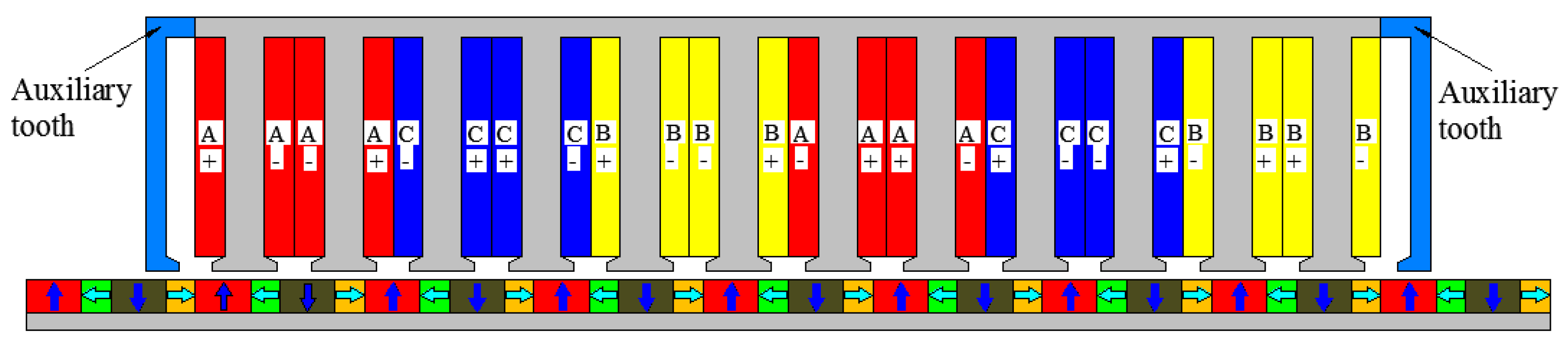
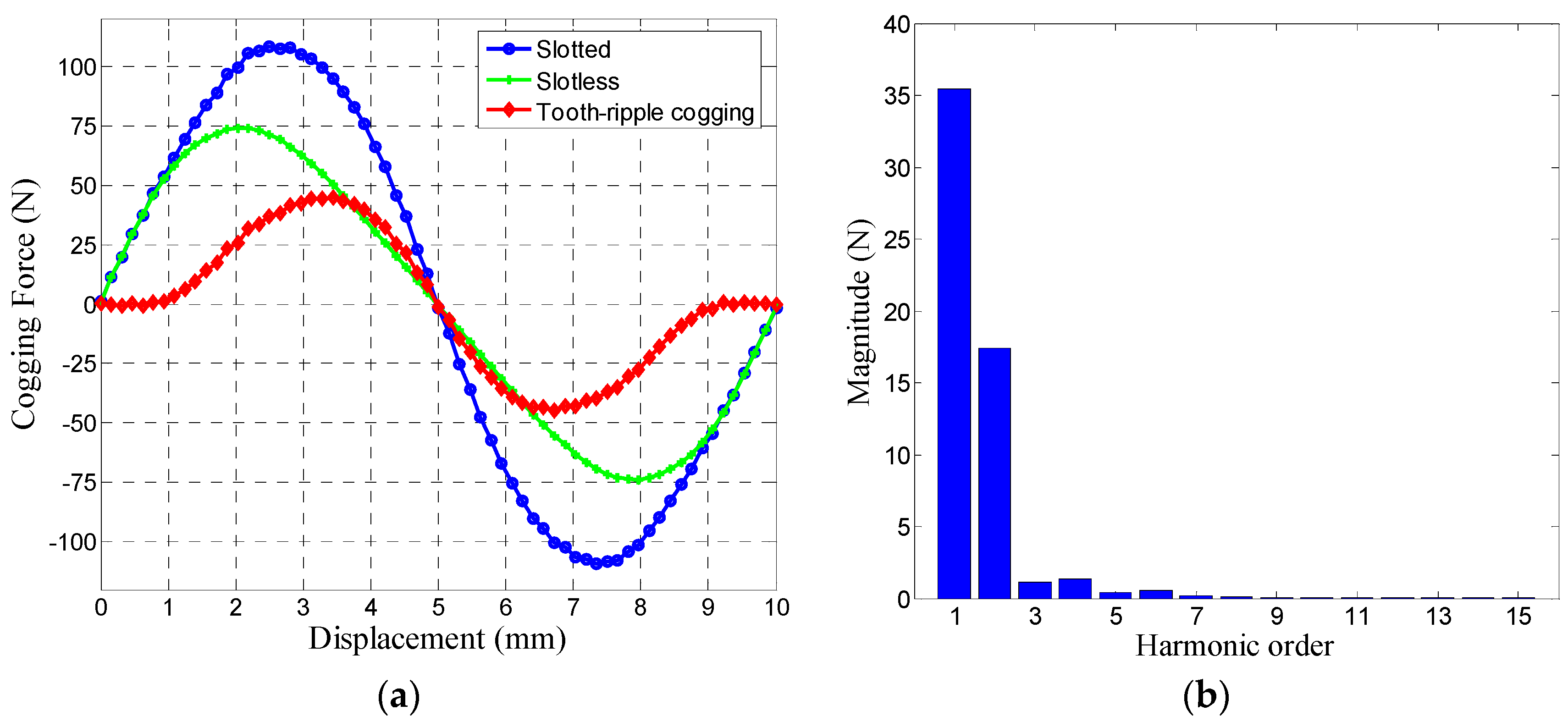
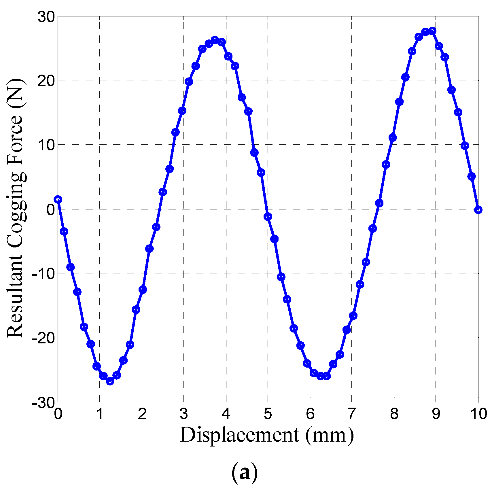
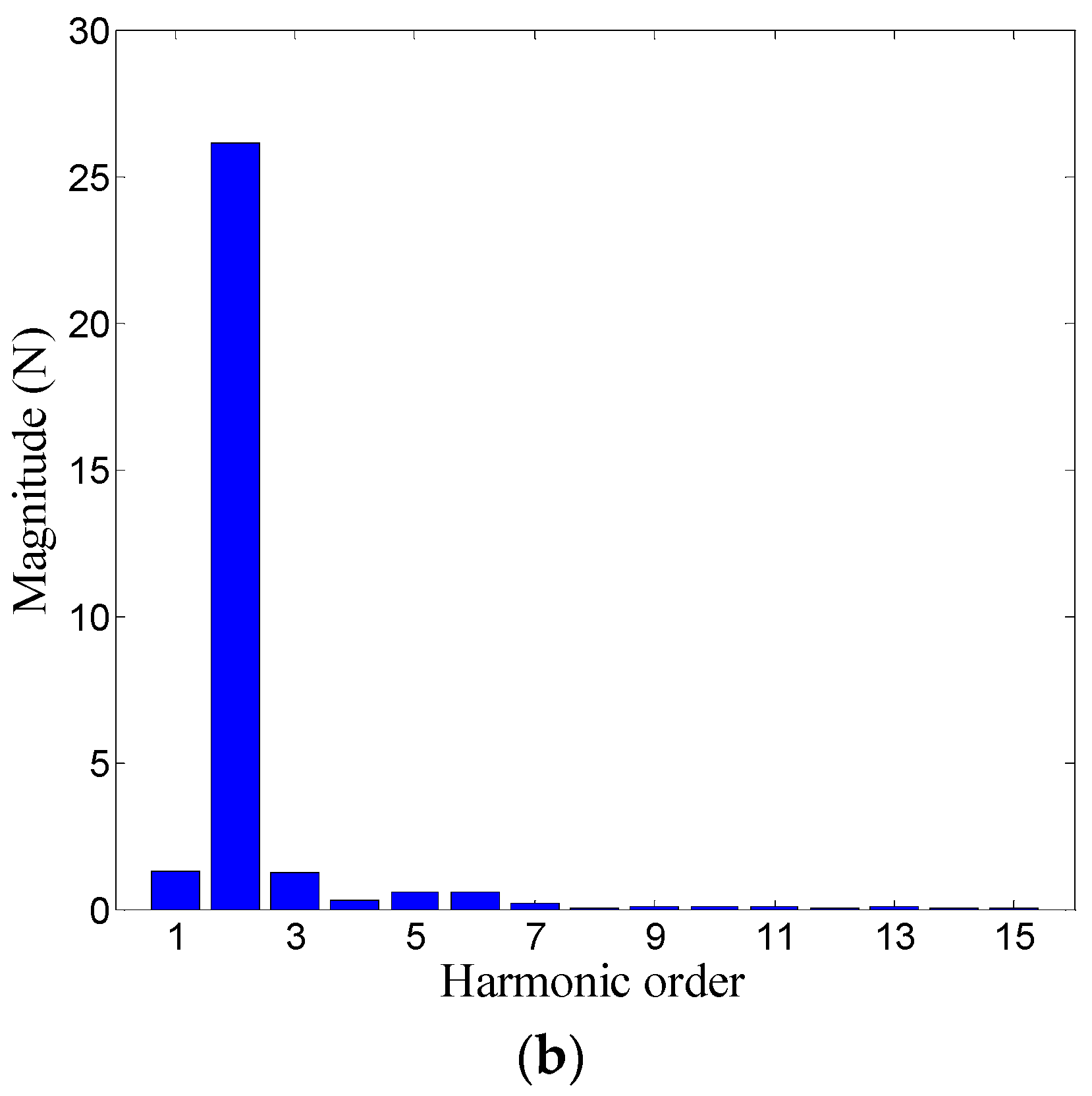
2. Tooth-Ripple Cogging Force in the Double-Layer Concentrated-Winding Design
In a PMLM with double-layer concentrated windings, due to the incorporation of an additional slot, the cogging force amplitude is mainly determined by the component arising from the additional slot [14]. Therefore, the cogging force is considerably higher than that in the single-layer-winding PMLM.
Figure 2 shows the FE model of a PMLM with double-layer windings, where the Dirichlet boundary condition is imposed at the outer surfaces. The primary parameters of the machine are listed in Table 1.
Figure 2.
Finite element model of the PMLM.
Table 1.
Specification and Leading Design Parameters of a permanent magnet linear motor (PMLM).
Figure 3 shows the tooth-ripple cogging force waveform and its harmonic spectrum.
Figure 3.
Cogging force in a PMLM with double-layer windings. (a) Waveform; (b) Harmonic spectrum of the tooth-ripple cogging.
It can be seen that the introduction of the auxiliary slot in the fractional-slot design gives rise to an additional tooth-ripple cogging force with a fairly high amplitude, accounting for 17.9% of the rated thrust force, which makes the fractional-slot design lose its strong capability of cogging force reduction. Therefore, extra effort is necessary for PMLMs with double-layer concentrated windings, to minimize the cogging forces.
Further observation on the harmonic spectrum in Figure 3b reveals that for the tooth-ripple cogging force, the fundamental and 2nd order harmonics are dominant. Therefore, in order to minimize the tooth-ripple cogging force, in practice it is generally adequate to take effective countermeasures to only eliminate the 1st and 2nd order harmonic components. In the following sections, two techniques, namely armature length optimization and magnet skewing, will be employed to reduce the two harmonic components, respectively.
3. Elimination of the 1st-Order Harmonic Cogging Force
Since the tooth-ripple cogging force has the same fundamental period as the end-effect cogging force, viz. one pole pitch, it is important to properly design the armature dimensions, so that the end-effect component is in an equal and opposite fashion to the tooth-ripple component, thus eliminating the 1st-order component of the resultant cogging force. In a more comprehensive way, the motional length of the steel core can be optimized to ensure that the 1st-order magnitude of the end-effect cogging force be equal to that of the tooth-ripple cogging force, and at the same time, the tooth widths at steel core ends are appropriately designed so that their initial phases have an offset of 180 electrical degrees.
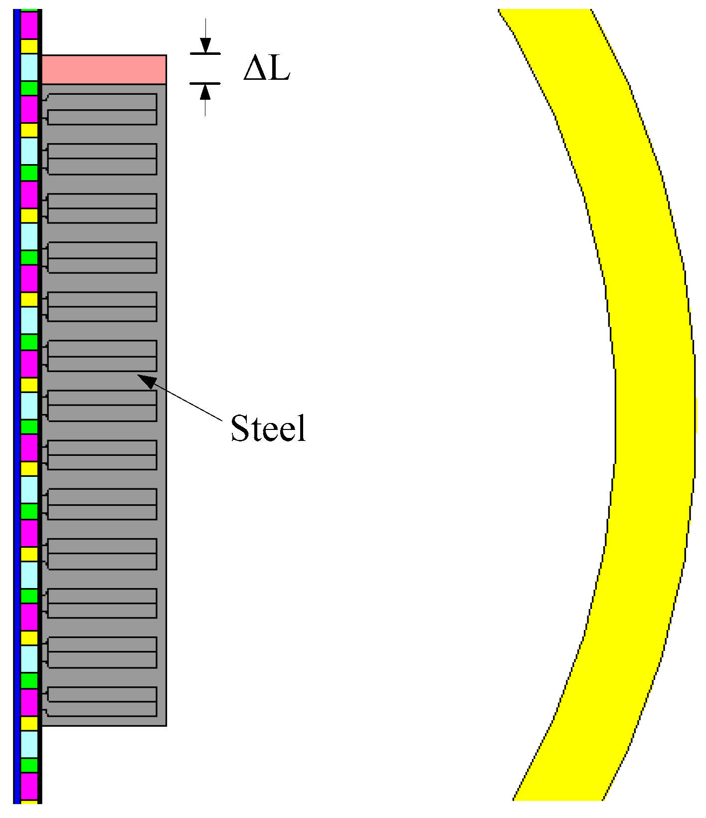
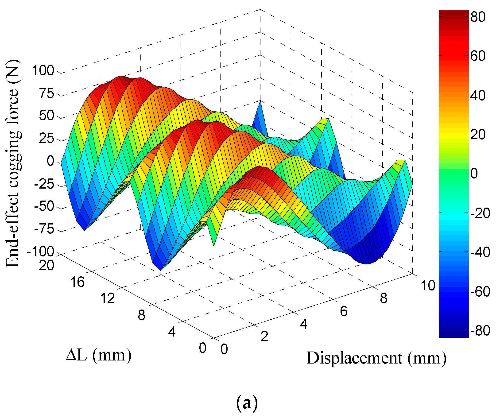
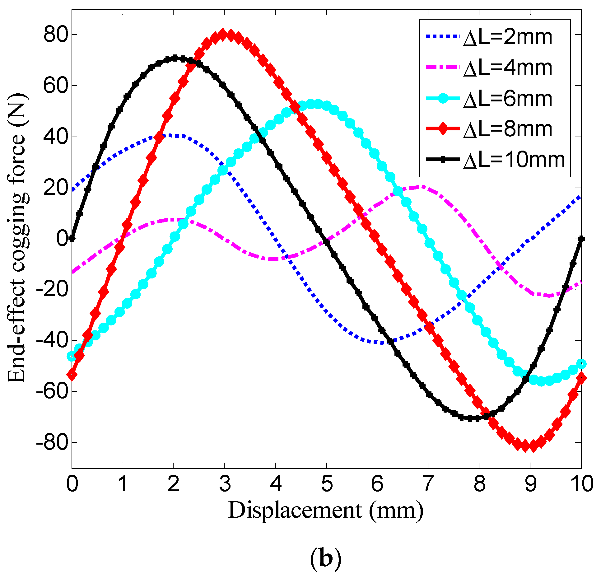
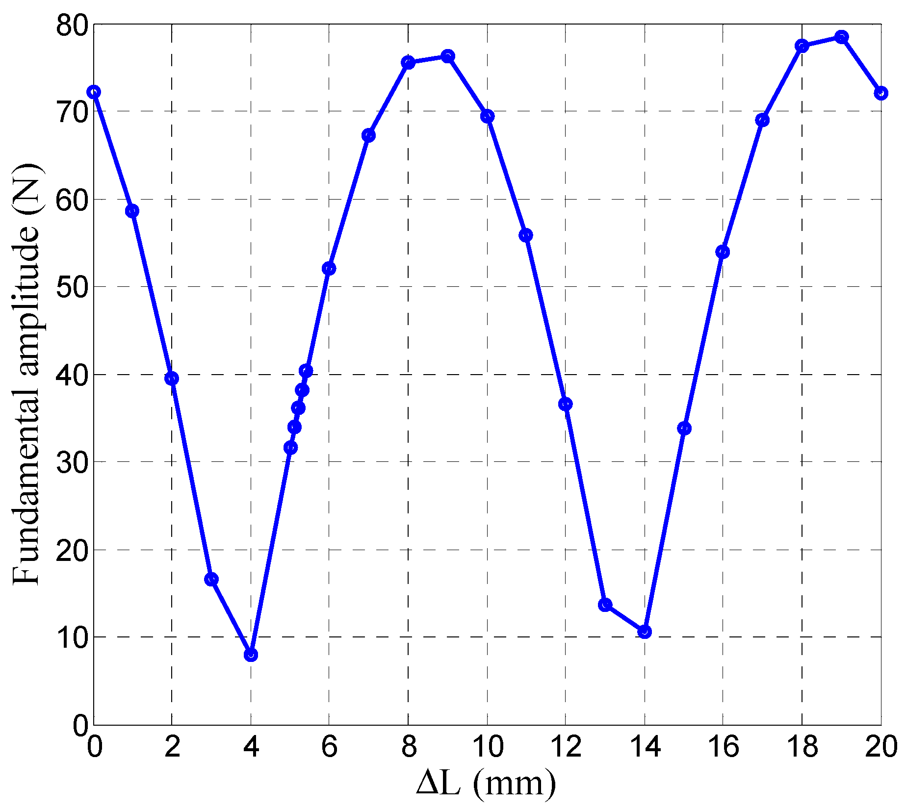
3.1. Influence of the Armature Core Length on the End-Effect Cogging Force
It has been reported in [8] that the magnitude of the end-effect cogging force is a function of the armature core length. In view of this, the armature length should be properly designed to maintain the amplitudes of the 1st-order component of the end-effect cogging force and the tooth-ripple cogging force as equal.
Using the FE model in Figure 4, the end-effect cogging force waveforms were obtained and are shown in Figure 5, where ΔL refers to the armature incremental length.
Figure 4.
Finite Element (FE) model of the slot-less PMLM with an auxiliary steel core.

Figure 5.
End-effect cogging force vs. mover displacement and ΔL. (a) 3-D view; (b) 2-D view.
More specifically, Figure 6 shows the variation of the 1st-order end-effect cogging amplitude along with ΔL. Particularly, when ΔL is equal to 5.2 mm, the 1st-order end-effect cogging amplitude is approximately equal to that of the tooth-ripple cogging force.
Figure 6.
First-order end-effect cogging amplitude as a function of ΔL.
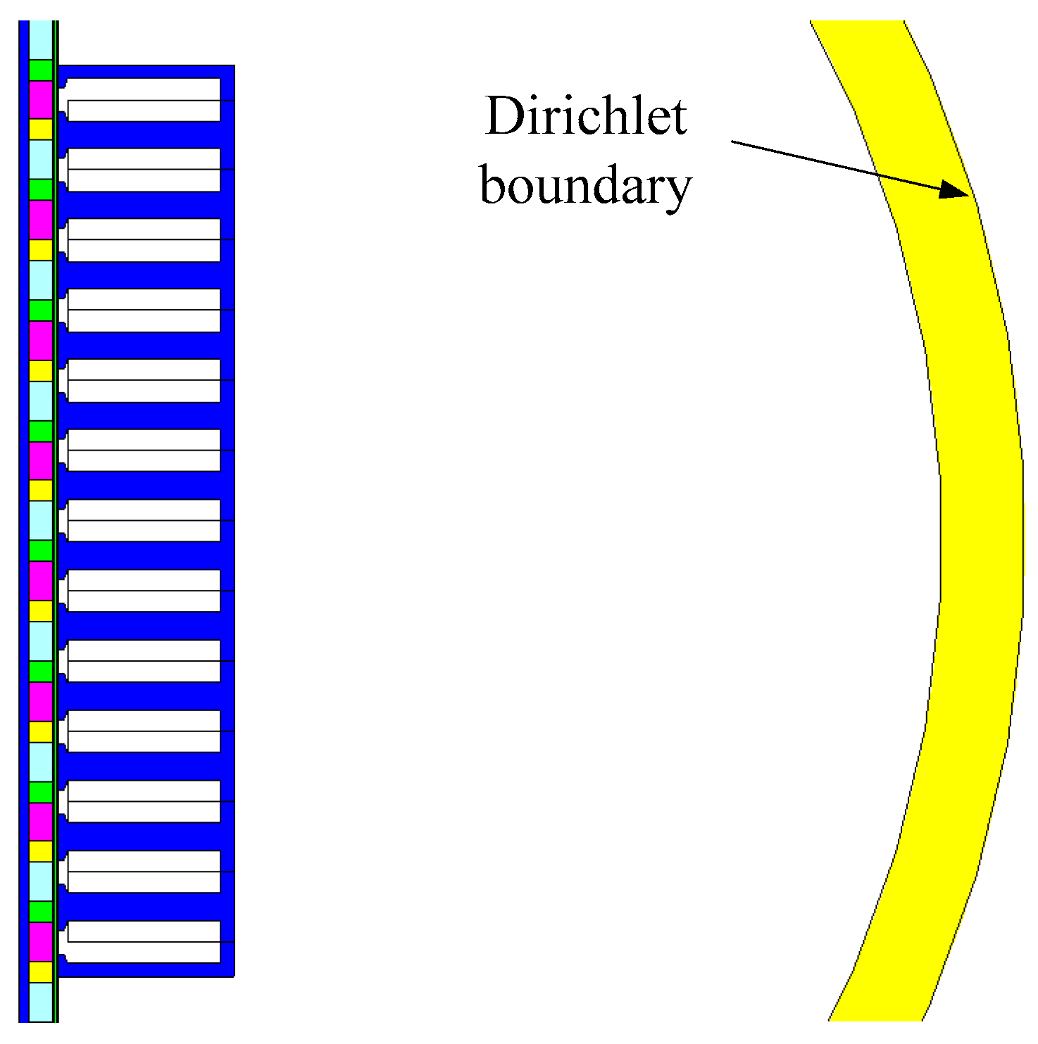
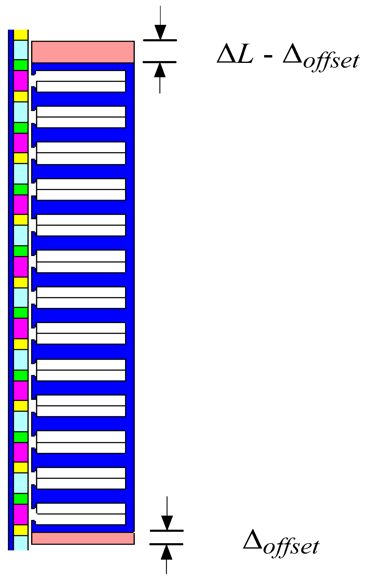
3.2. Phase Adjustment by Offsetting the Auxiliary Core
In order to eliminate the 1st-order harmonic cogging force, apart from the magnitude requirement, the initial phase of the 1st-order harmonic end-effect cogging force should be designed with an offset of 180 electrical degrees to that of the tooth-ripple cogging force, which can be achieved by offsetting the auxiliary core, as shown in Figure 7.
Figure 7.
Initial phase adjustment of the end-effect cogging force by offsetting the auxiliary core.
Assuming that the initial phases of the 1st-order end-effect and tooth-ripple components are θ1 and θ2 (in electrical degrees), respectively, the offset of the auxiliary core can be calculated as
In this case, θ1 is −90.02°, and θ2 is −175.45° when ΔL is designed as 5.2 mm. Accordingly, the offset of the auxiliary core should be 2.62 mm.
3.3. Validations
Figure 8 gives the waveform of the resultant cogging force of the PMLM after performing both the armature core optimization and the auxiliary core offset.

Figure 8.
Resultant cogging force after performing the armature core optimization and the auxiliary core offset. (a) Waveform; (b) Harmonic spectrum.
It can be seen that by adopting the techniques of both optimizing the armature length and offsetting the auxiliary core, the 1st-order component of the resultant cogging force has been reduced drastically, thus verifying the validity of the above proposed method.
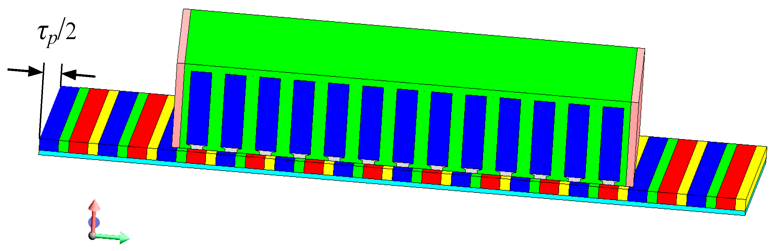
4. Elimination of the 2nd-Order Harmonic Cogging Force
After utilizing the techniques in Section 3, the 1st-order component of the cogging force has been greatly reduced. The dominant component is now the 2nd-order harmonic, and it can be eliminated by skewing the magnets by τp/2, i.e., the wavelength of the 2nd-order harmonic, since skewing magnets reduces the magnetic reluctance variation seen by the armature, and thus minimizes the cogging force. Figure 9 illustrates the schematic of a linear machine equipped with skewed magnets.
Figure 9.
Schematic of the use of skewed magnets for cogging force reduction in a linear machine.
4.1. Analytical Analysis
The analytical analysis of the cogging force in the PMLM, which employs skewed magnets, is derived below. Firstly, if the magnets are straight, the resultant cogging force Fr, which comprises both the tooth-ripple cogging Fslot and the end-effect cogging Fend, can be expressed by
where x is the mover displacement, and Fn and θn are the amplitude and initial phase of the nth-order component, respectively.
By skewing the magnets by τp/2, the resultant cogging force can be calculated as
As can be seen from Equation (3), the technique of magnet skewing has the following impacts, namely:
- (1).
- When n = 2, 4, 6, ..., sin(nπ/2) = 0, which means that the even-order components of the cogging forces can be eliminated by skewing the magnets by τp/2.
- (2).
- The magnitudes of the other harmonic cogging-forces can be brought down with a factor (2/nπ).
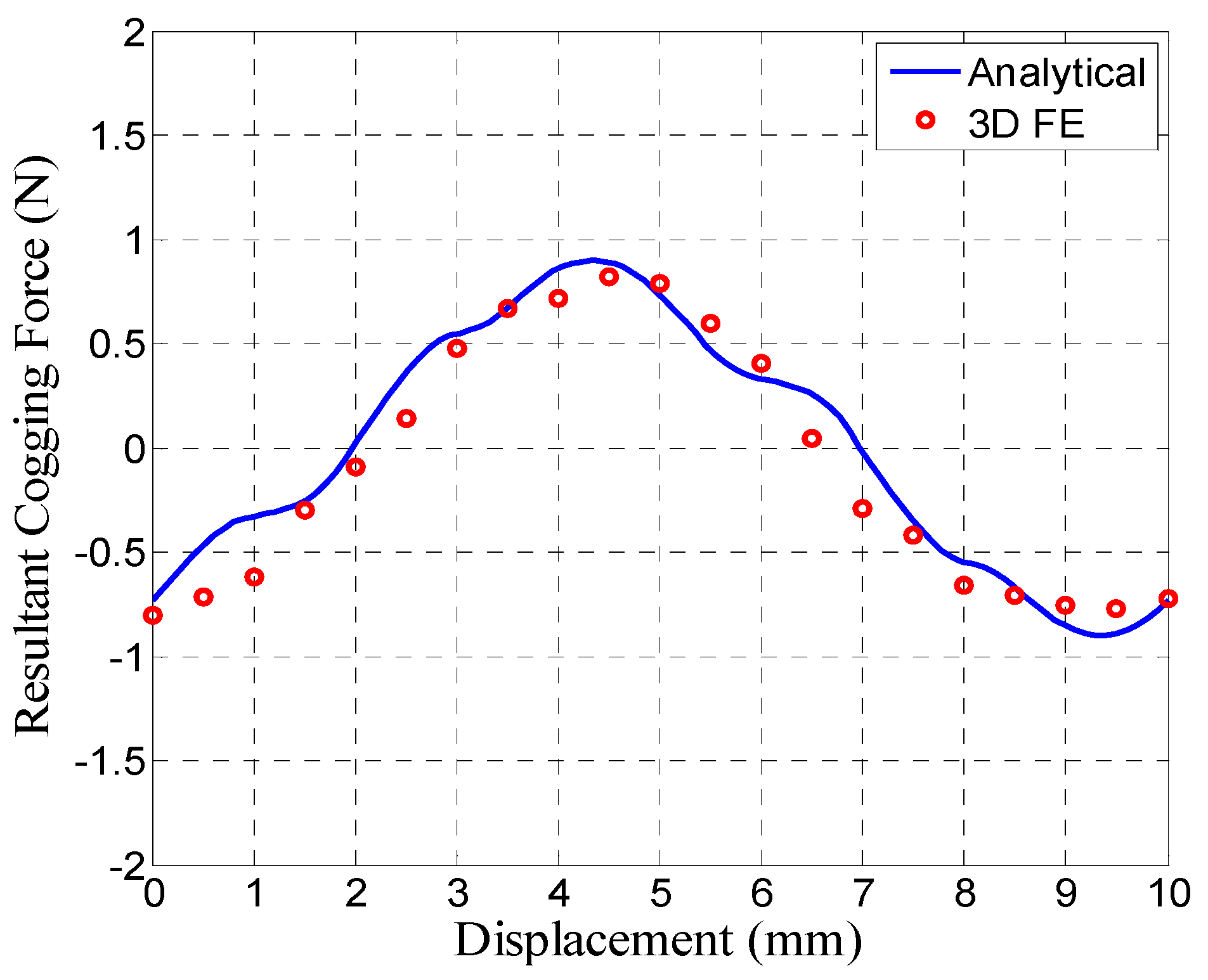
4.2. Validations
In order to account for the skewing effect on the cogging force reduction, 3-dimensional (3D) FE analysis was applied to calculate the cogging force of the PMLM with skewed magnets. Figure 10 displays the result, together with the analytically predicted waveform for comparison, which was derived from Equation (3).
Figure 10.
Cogging force waveform of the PMLM with skewed magnets.
It can be observed that by skewing the magnets by τp/2, the cogging force has been greatly reduced; the amplitude decreased from 27.6 N initially to nearly 0.9 N, accounting for less than 0.4% of the rated force. There is a small error between the FE calculations and the analytical predictions, which may be mainly attributed to computation error and the transverse edge effect that are not taken into account in the analytical derivation. Nevertheless, the results have confirmed the effectiveness of this approach.
5. Practical Considerations
5.1. Skewing Magnets by τp—A High Price
At this stage, one might wonder that why not directly skew the PMs by one pole pitch, instead of half a pole pitch, to eliminate both the tooth-ripple and end-effect cogging forces, since both have a fundamental period of τp. Truly, skewing the PMs in this manner would achieve the expected elimination of the cogging force, but the cost of an excessive loss of the back electromotive force, and hence the power, must be paid. From this point of view, skewing the PMs by half a pole pitch proves to be a better solution which compromises the cogging force and the power density.
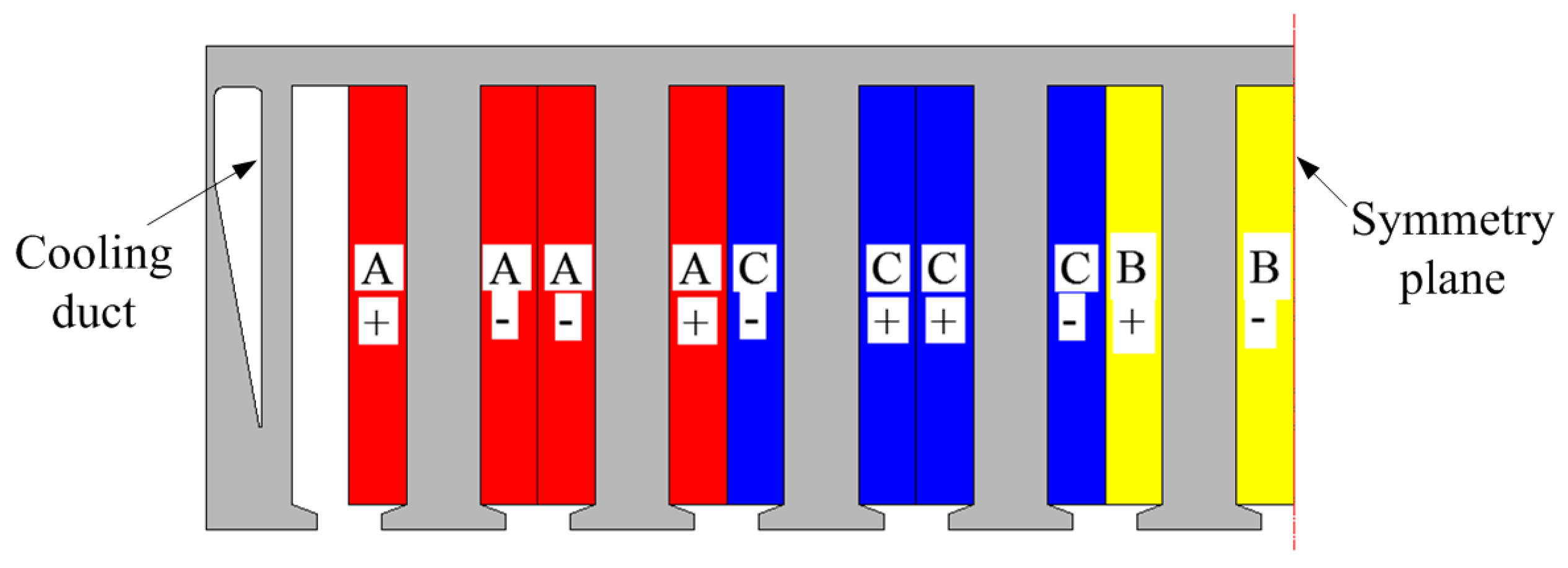
5.2. Incorporation of Cooling Ducts into Armature Cores
It should be pointed out that due to the introduction of the auxiliary teeth, the force density of the linear PM motor would be slightly decreased. In order to minimize this impact, ducts can be incorporated into the armature cores to reduce the weight, as illustrated in Figure 11. Furthermore, the ducts can also be utilized for cooling and are conducive to improving the heat transfer from the cores and windings. However, the dimensions and positions of the ducts should be carefully optimized to have minimal effect on the magnetic field distribution, which is beyond the scope of this paper.
Figure 11.
Incorporation of cooling ducts into armature cores.
6. Conclusions
This paper has studied minimization techniques in a fractional-slot PMLM with double-layer concentrated windings. The following key observations can be drawn:
- (1).
- The PMLM with double-layer concentrated windings exhibits significant tooth-ripple cogging force even with the fractional-slot technology.
- (2).
- By combining the optimized design of armature core dimensions with magnet skewing, the 1st- and 2nd-order cogging forces have been eliminated, and in this way, the resultant cogging force can be greatly minimized.
- (3).
- The approach described in the paper is capable of reducing the cogging force in an effective way, which is conducive to the expanded use of PMLMs in a range of applications. Such techniques can be readily extended to other linear PM machines.
Acknowledgment
This work was supported in part by the Natural Science Foundation of China under Grant 51407047, by the National Key Basic Research Program of China under Grant 2013CB035600, and by the China Postdoctoral Science Foundation under Grant 2014M551241.
Author Contributions
The paper was a collaborative effort between the authors. The authors contributed collectively to the theoretical analysis, modeling, simulation, and manuscript preparation.
Conflicts of Interest
The authors declare no conflicts of interest.
References
- Kou, B.; Luo, J.; Yang, X.; Zhang, L. Modelling and analysis of a novel transverse-flux flux-reversal linear motor for long-stroke application. IEEE Trans. Ind. Electron. 2016, 10, 6238–6248. [Google Scholar] [CrossRef]
- Teo, T.J.; Zhu, H.; Pang, C.K. Modeling of a two degrees-of-freedom moving magnet linear motor for magnetically levitated positioners. IEEE Trans. Magn. 2014, 12, 8300512. [Google Scholar] [CrossRef]
- Ji, J.; Yan, S.; Zhao, W.; Liu, G.; Zhu, X. Minimization of cogging force in a novel linear permanent-magnet motor for artificial hearts. IEEE Trans. Magn. 2013, 7, 3901–3904. [Google Scholar] [CrossRef]
- Gandhi, A.; Parsa, L. Thrust optimization of a flux-switching linear synchronous machine with yokeless translator. IEEE Trans. Magn. 2013, 4, 1436–1443. [Google Scholar] [CrossRef]
- Tavana, N.R.; Shoulaie, A. Pole-shape optimization of permanent-magnet linear synchronous motor for reduction of thrust ripple. Energy Convers. Manag. 2011, 52, 349–354. [Google Scholar] [CrossRef]
- Wang, Q.; Zou, J.M.; Zou, J.B.; Zhao, M. Analysis and computer-aided simulation of cogging force characteristic of a linear electromagnetic launcher with tubular transverse flux machine. IEEE Trans. Plasma Sci. 2011, 1, 157–161. [Google Scholar] [CrossRef]
- Kim, Y.J.; Watada, M.; Dohmeki, H. Reduction of the cogging force at the outlet edge of a stationary discontinuous primary linear synchronous motor. IEEE Trans. Magn. 2007, 1, 40–45. [Google Scholar] [CrossRef]
- Zhu, Z.Q.; Xia, Z.P.; Howe, D.; Mellor, P.H. Reduction of cogging force in slotless linear permanent magnet motors. IEE Proc. 1997, 4, 277–282. [Google Scholar] [CrossRef]
- Inoue, M.; Sato, K. An approach to a suitable stator length for minimizing the detent force of permanent magnet linear synchronous motors. IEEE Trans. Magn. 2000, 4, 1890–1893. [Google Scholar] [CrossRef]
- Zhu, W.; Lee, S.; Chung, K.; Cho, Y. Investigation of auxiliary poles design criteria on reduction of end effect of detent force for PMLSM. IEEE Trans. Magn. 2009, 6, 2863–2866. [Google Scholar] [CrossRef]
- Wang, J.; Inoue, M.; Amara, Y.; Howe, D. Cogging-force-reduction techniques for linear permanent-magnet machines. IEE Proc. 2005, 3, 731–738. [Google Scholar] [CrossRef]
- Jung, I.; Hur, J.; Hyun, D. Performance analysis of skewed PM linear synchronous motor according to various design parameters. IEEE Trans. Magn. 2001, 5, 365–3657. [Google Scholar]
- Hor, P.J.; Zhu, Z.Q.; Howe, D.; Jones, J. Minimization of cogging force in a linear permanent magnet motor. IEEE Trans. Magn. 1998, 5, 3544–3547. [Google Scholar] [CrossRef]
- Wang, Q.; Wang, J. Assessment of cogging-force-reduction techniques applied to fractional-slot linear permanent magnet motors equipped with non-overlapping windings. IET Electr. Power Appl. 2016, 8, 697–705. [Google Scholar] [CrossRef]
- Zhao, S.; Tan, K.K. Adaptive feed forward compensation of force ripples in linear motors. Control Eng. Pract. 2005, 13, 1081–1092. [Google Scholar] [CrossRef]
- Bianchi, N.; Bolognani, S.; Cappello, A. Back EMF improvement and force ripple reduction in PM linear motor drives. In Proceedings of the 2004 IEEE 35th Annual Power Electronics Specialists Conference, Aachen, Germany, 20–25 June 2004; pp. 3372–3377.
- Jahns, T.M.; Soong, W.L. Pulsating torque minimization techniques for permanent magnet AC motor drives—A review. IEEE Trans. Ind. Elec. 1996, 2, 321–330. [Google Scholar] [CrossRef]
- Hwang, C.C.; Li, P.L.; Liu, C.T. Optimal design of a permanent magnet linear synchronous motor with low cogging force. IEEE Trans. Magn. 2012, 2, 1036–1042. [Google Scholar] [CrossRef]
- Youn, S.W.; Lee, J.J.; Yoon, H.S.; Koh, C.S. A new cogging-free permanent-magnet linear motor. IEEE Trans. Magn. 2008, 7, 1785–1790. [Google Scholar] [CrossRef]
© 2016 by the authors; licensee MDPI, Basel, Switzerland. This article is an open access article distributed under the terms and conditions of the Creative Commons Attribution (CC-BY) license (http://creativecommons.org/licenses/by/4.0/).