Abstract
In this paper, a power management strategy (PMS) has been developed for the control of energy storage in a system subjected to loads of random duration. The PMS minimises the costs associated with the energy consumption of specific systems powered by a primary energy source and equipped with energy storage, under the assumption that the statistical distribution of load durations is known. By including the variability of the load in the cost function, it was possible to define the optimality criteria for the power flow of the storage. Numerical calculations have been performed obtaining the control strategies associated with the global minimum in energy costs, for a wide range of initial conditions of the system. The results of the calculations have been tested on a MATLAB/Simulink model of a rubber tyre gantry (RTG) crane equipped with a flywheel energy storage system (FESS) and subjected to a test cycle, which corresponds to the real operation of a crane in the Port of Felixstowe. The results of the model show increased energy savings and reduced peak power demand with respect to existing control strategies, indicating considerable potential savings for port operators in terms of energy and maintenance costs.
1. Introduction
Energy storage is beneficial in situations where power production is intermittent or the load varies in intensity, as the objective of the storage is to mitigate variability in generation and demand by acting as a buffer. Economical feasibility limits the size and power rating of the storage system, resulting in the need to optimise the power flow in order to maximise the efficacy of the limited available resources. In the case of a known load profile, it is possible to define a strategy that results in the optimal solution for a given storage system, placing the focus on finding the most suited technology for the single application. Slow processes get the most benefit from using batteries or other forms of high-capacity storage systems (compressed air, pumped hydro, etc.), while fast loads characterised by short and high power demand are paired with flywheels, supercapacitors or other technologies capable of reacting in a very short time, outputting relatively high power [1,2,3]. Usually, the variability of the load also depends on the time constant of the application: the power demand in regional power network fluctuations is periodical with peaks occurring at around the same time of the day and of the year, leading to optimal solutions for power management that account for the deviation from the typical daily or yearly profile [4,5,6,7,8]. When loads are limited to a short period of time (tens of seconds or less), the variability tends to be defined by three main factors: when the demand occurs, its intensity and duration. As an example, electric vehicles show this sort of unpredictability, as there is no prior knowledge of the acceleration that the driver requires when driving, and therefore, the stochastic behaviour of the demand is taken into account when developing control strategies [9,10,11].
The focus of this paper is to develop an optimal control strategy to be applied to energy storage in rubber tyre gantry (RTG) cranes, which are found in container ports and whose task is to stack containers in the yard area. Most of the energy consumption comes from hoisting containers (weighing up to 54 tons) for a typical full height of 15 m at vertical speeds that can reach 0.85 m/s, resulting in short intense loads of limited durations. In order to reduce the stress on the primary source, which can be either a diesel generator or the port’s electrical network, energy storage can be used for peak shaving during the lifting phase and to recover potential energy during the lowering phase [12,13,14]. Although other authors proposed RTG cranes equipped with batteries [13], these are best suited for reducing idle power consumption due to their low power density. Flywheels and supercapacitors are more suited for the high power flows deriving from the hoist motor (both when motoring and generating), and they have been the subject of multiple studies [12,14,15,16,17]. Flywheel energy storage systems (FESSs) in particular have been found particularly suited for this task, as they show similar performance to supercapacitors, while being characterised by excellent ageing characteristics, which are independent of the charge rate or depth of discharge [1,18], allowing their lifetime to match that of the portal frame. Their disadvantage is high standing losses, which are particularly evident in more resilient designs (such as the use of normal ball bearings instead of magnetic bearings), as are the ones used on cranes; however, this does not affect the use for short power loads, and it only requires the storage to be charged shortly before use. Energy storage then can be beneficial for the reduction of energy demand and also peak power demand; for this reason, it is critical to develop a power management strategy (PMS) that takes full advantage of the storage capacity, while keeping its cost at the minimum. An effective control strategy focused on storage in RTG cranes could have major benefits globally, as they are present in all major container ports and are a key element in the export and import processes. Their activity is energy and power intense; nonetheless, it involves spending a large fraction of time idling before the next lift cycle. In a typical cycle, a container lift is preceded by a lowering of the headblock mechanism (which securely locks to the container) and a locking sequence, giving a forewarning of the incoming lifting cycle. The weight of the container that will need to be lifted is known, as cranes need to measure the weight for safety reasons, giving a good estimate of the power demand of the following lift. The only remaining variability is the duration of the load; it is usually unknown (apart from a few ports with advanced terminal operating systems) with the duration being proportional to the height that the container needs to reach in a specific lift cycle, and it depends on the configuration of the stack in the precise location.
This paper introduces a novel PMS, which optimises the use of storage under uncertainties on the duration of power loads, unlike previous works that assume full knowledge of the load profile [11,13,19,20]. The aforementioned PMS is tailored for load characterised by known intensity and random duration, representing the power consumption caused by the lifting of containers; nonetheless, it could also be applied to any hybrid system characterised by loads of unknown duration. The paper is organised as follows: Section 2 describes the topology of the power system. Section 3 presents the optimal control problem and the proposed PMS. The RTG model and the simulation results are presented and discussed in Section 4, with Section 5 presenting a summary of the work.
2. System Topology
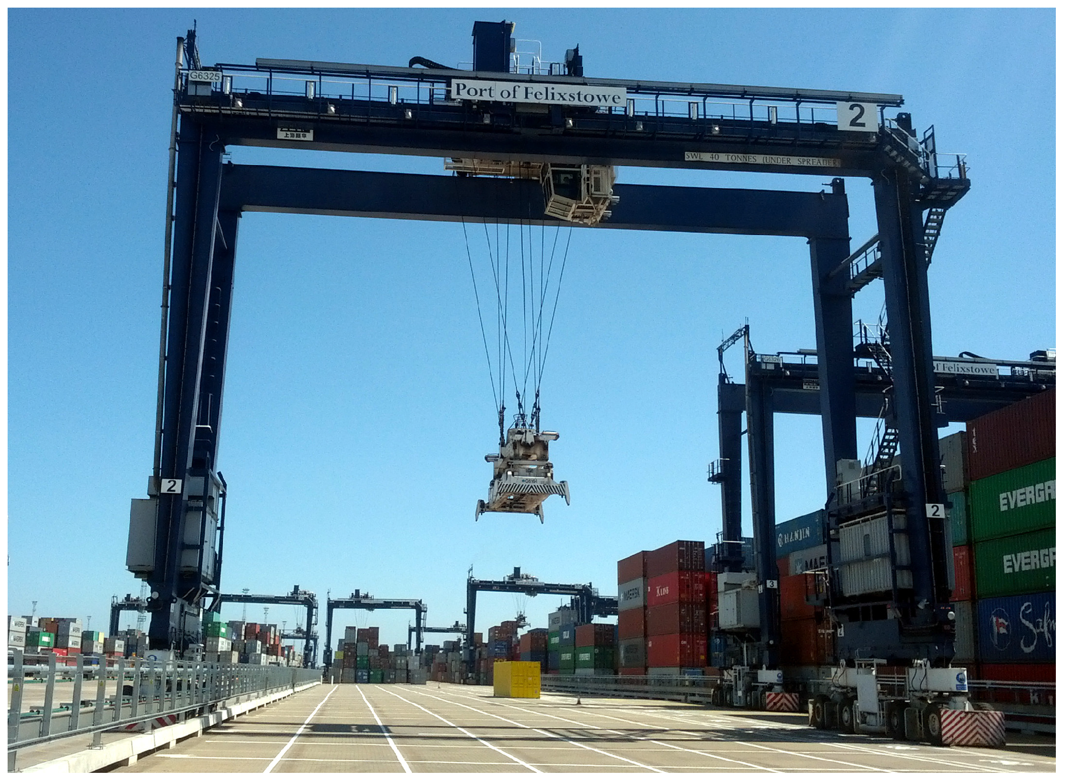
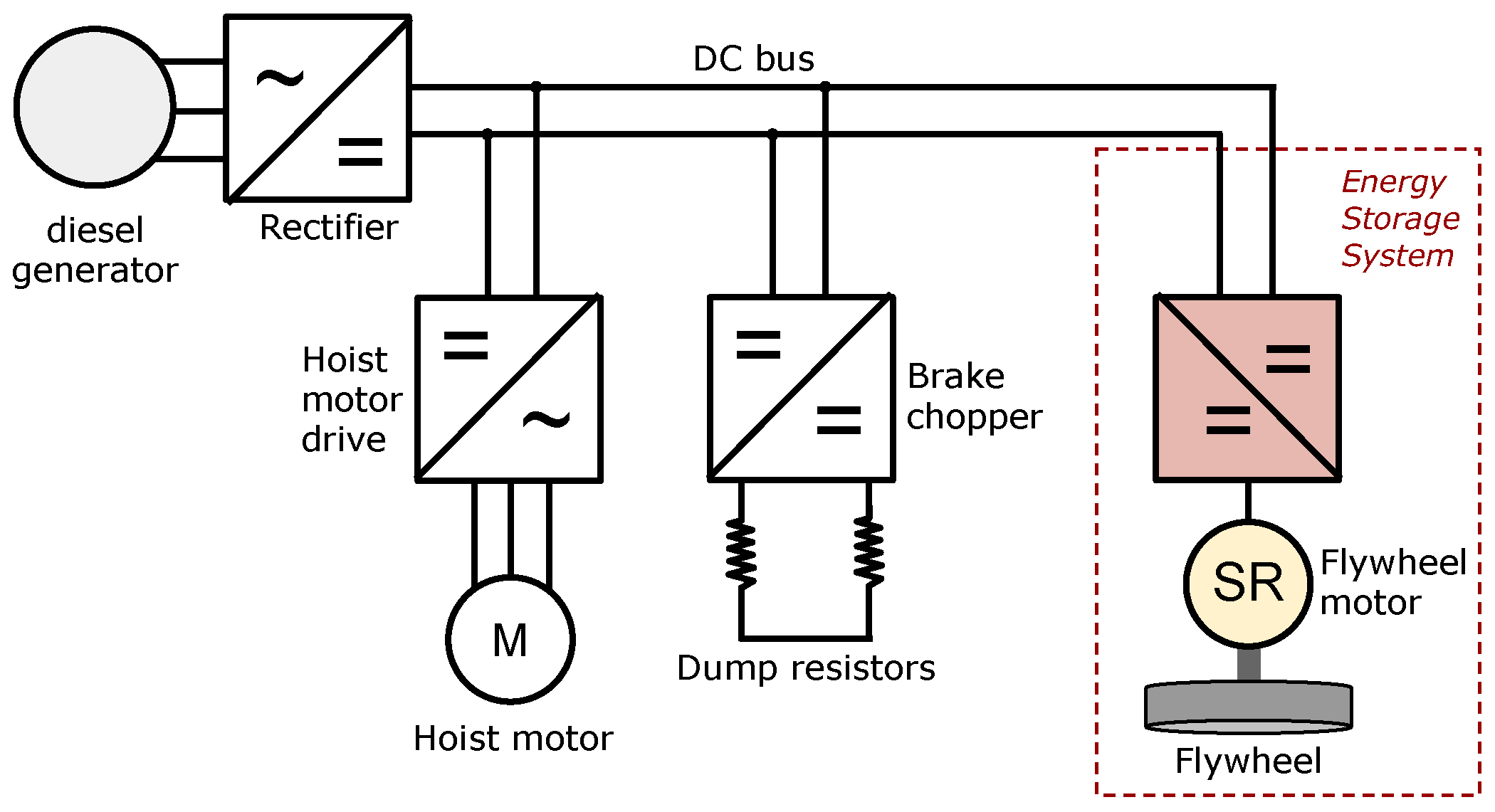
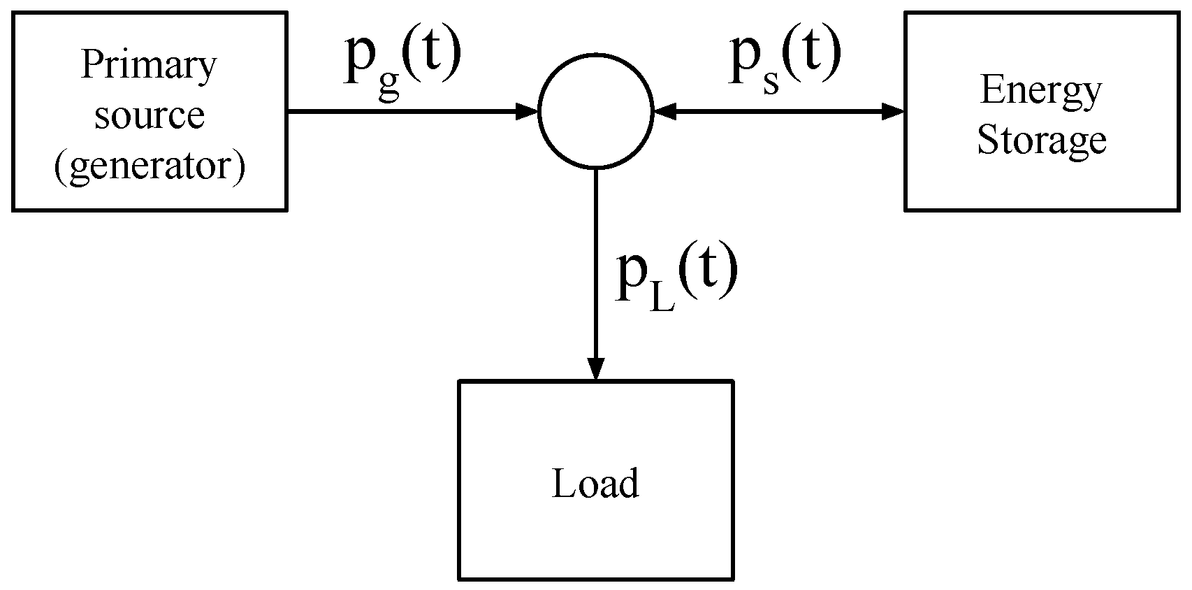
The RTG crane under analysis, shown in Figure 1, is manufactured by Shanghai Zhenhua Heavy Industries (ZPMC), and it is currently used at the Port of Felixstowe. It is equipped with a diesel generator, but it is has also been retrofitted with a connection to the terminal power network through a conductor bar running along the stack, allowing it to be powered by the electric grid without using the diesel generator. The simplified diagram in Figure 2 shows the primary energy source (either generator or grid) connected to a diode rectifier, which powers a DC bus. The main motors (hoist, gantry, trolley, etc.) are all connected to the shared DC bus, as well as the brake resistors, which engage automatically when the DC bus voltage raises above 750 V. The energy storage can be connected to the bus, drawing current when the voltage raises above a threshold (regeneration phase) and supplying power according to a PMS. The energy storage system consists of a motor drive, a switched reluctance (SR) motor and a flywheel coupled to its axis. The primary energy source supplies all of the power that is required for the DC bus, which is the power consumption of the motors minus the power supplied by the storage . As in [19,21], the power system can be represented as shown in Figure 3, where the load, the generated power and the power from the storage are respectively , and , resulting in the following equation:
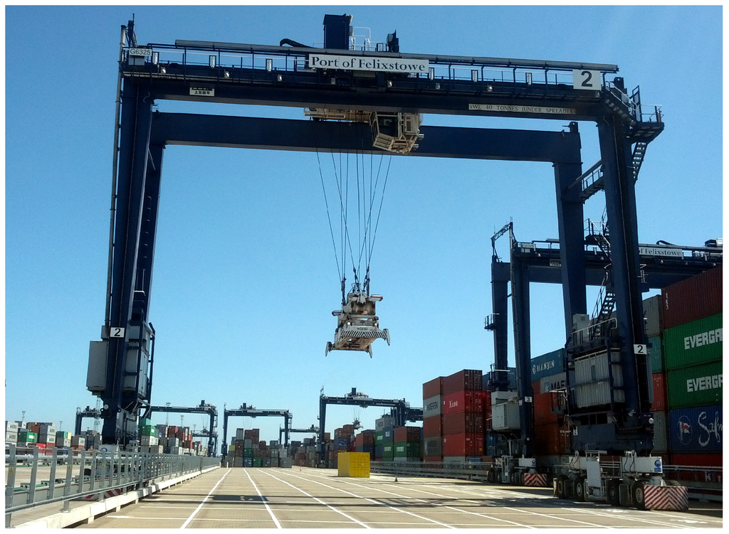
Figure 1.
A rubber tyre gantry crane.
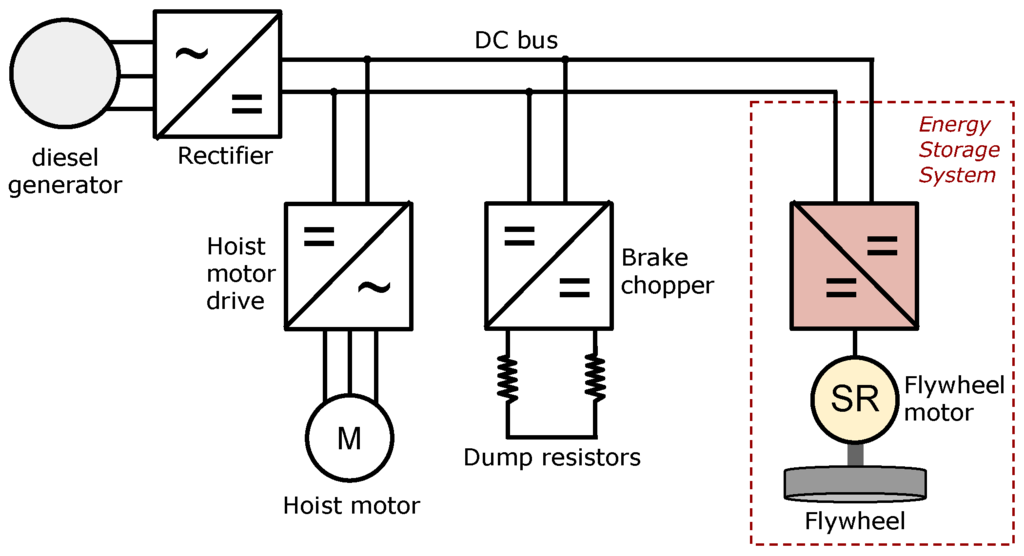
Figure 2.
Simplified diagram of the main electric components of an RTG crane.
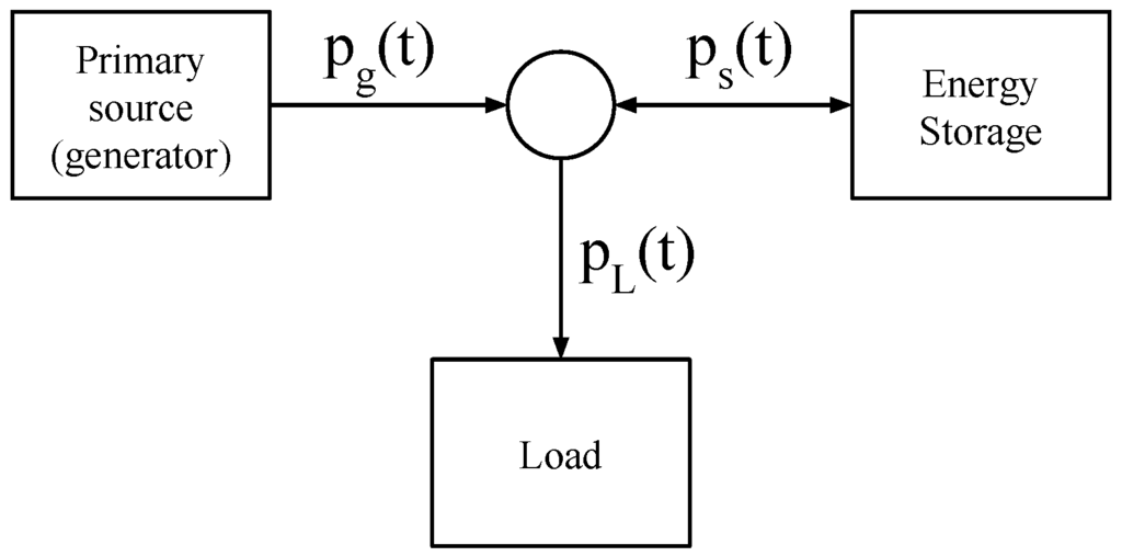
Figure 3.
Topology of the power system.
2.1. The Primary Source
The main power supply provides all of the power demanded by the crane motors, and it can be represented as an infinite source of power and energy, as both the diesel generator and the power network supply are rated above the maximum possible load of the crane. It is unidirectional, as power cannot be converted back to fuel or regenerated into the grid (due to the absence of an active front-end) and has a cost associated with every unit of energy delivered. This cost is represented by the positive definite function , and it encompasses fuel consumption, efficiency and aggregated fixed costs (higher power consumptions have a relatively higher cost due to the need for larger generators). The objective of the proposed PMS is to use the stored energy to minimise the total cost of the energy production for the duration of a lift, which is:
with T indicating the maximum possible duration of the lift cycle.
2.2. The Load
During a lift, the power required by the hoist motor is assumed known and constant with value . Nonetheless, the value of is not known for every instant, as the duration of the lift is unknown. The load profile can then be simplified as follows:
where represents the final time of the lift and is a random variable modelled by a distribution, which is assumed known. It would be possible to calculate the optimal assuming a deterministic and well-known load profile [19,20], but in the case discussed in this paper, the load behaviour is stochastic, creating a new challenge.
2.3. The Energy Storage
An FESS stores recovered energy obtained from lowering containers in the form of a rotating mass, whose angular speed gives an exact value of the stored energy :
where J is the flywheel inertia and ω is the angular speed. To limit torque output and wear, the flywheel will have an actual range of speeds limited by a lower limit and an upper limit , so the usable energy at time t will be the following:
and it will also be bounded:
with the energy corresponding to the maximum speed .
The flywheel is powered by an electric motor, which is assumed equipped with a control system that is able to follow with negligible delay the instantaneous power command issued by the PMS. Given the high standing losses of a flywheel storage system, it is necessary to model a system that loses energy over time with the following approximation:
where is a constant value that links losses to the stored energy (friction and windage losses), is a constant power loss, which is independent of the quantity of stored energy (e.g., power supply, cooling), and finally, is the power exchanged with the system. The values for and can be measured or estimated from the characteristics of the storage.
3. Optimal Power Management Strategy
The objective is to minimise the total cost expressed in Equation (2), which is associated with the generated energy. The optimal controller should then be designed to find the storage output that minimises Equation (2), which, given Equation (1), is equal to:
The cost function for generated power is assumed to result in no cost when no power is demanded (i.e., ). Therefore, knowing from Equation (3) that when , we can reduce the limits of the integral in Equation (8), as the integrand will be zero if we choose the trivial solution (corresponding to no storage output when there is no load):
The total cost value in Equation (9) is calculated for a specific , which, in reality, is a random value whose distribution L is known. To account for the stochastic behaviour, it is then necessary to calculate the expected value of the total cost, by considering a single value of weighted by the probability of its occurrence. By defining as the probability that a certain occurs, the expected value of the cost is the following:
where T is the maximum possible value of . We can assume that , as the container lifts have positive duration, and also , as the duration is finite. Equation (10) spans the whole range of possible values of and calculates the cost of applying a certain control strategy in all possible scenarios, weighting the cost with the probability of that scenario to occur. An optimal control strategy is then one that satisfies:
By defining , the cumulative distribution function (CDF) [22] of the probability density function , we have:
and has the property that the final value is one:
The integrand represents finite quantities, and it can be assumed that:
as the load energy is limited (from Equation (3)), as well as the stored energy. When taking into account Equations (12) and (14), the expression in Equation (11) is equivalent to:
which is a more manageable form of minimisation, as it involves a single integrand when the CDF is known. The proof of Equation (15) is located in Appendix A.
3.1. Constraints
The problem in Equation (15) has the trivial solution of setting if the available stored energy is infinite. In the real world, the energy capacity will be limited, and this is reflected by adding the constraint Equation (6), which will have the practical effect of limiting the amount of energy that can be provided by the storage, creating a limited fuel problem:
Furthermore, the dynamics of the storage system with its losses need to be taken into account; the expression in (7) dictates how the system loses energy over time; hence, Equation (16) is too approximative and overestimates the available energy, so it needs to be replaced by Equation (17).
The last constraint is the power rating of the storage, which cannot exceed the maximum rated value, and it is assumed to be the same, in absolute value, when motoring and generating:
This type of optimal control problem has not yet been solved analytically [23,24,25], but it can be solved numerically by dynamic programming, accurately reducing the number of combinations to iterate through.
3.2. Numerical Calculation
The non-convex problem defined in Equation (15), with the domain defined by the constraints in Equations (17) and (18), has been discretised in order to perform the numerical minimisation. This is because the numerical calculation requires the quantisation of the instantaneous control value , subject to constraints that are difficult to include in the minimisation process.
where is the chosen sampling time. To represent the cost, , it has been chosen as , as it indicates the higher costs associated with higher power demands to the generator and the network. The constraint expressed in Equation (17) is discretised, as well:
The search space for the minimisation is reduced by parametrising the control function using an interpolation method that maintains the monotonicity of the function. The method chosen is piecewise cubic Hermite interpolating polynomial (PCHIP) [26,27], which is a variant of cubic Hermite interpolation, which, unlike methods like spline and Bessel , preserves monotonicity, avoiding “bumps” and overshoots in the resulting signal. A PCHIP interpolant is continuously differentiable, and its extrema are located at the extremal points. An interpolant function is generated from a finite number N of data points , which are then the values of the control signal. The number of values N define the complexity of the interpolant and also the computing time; N must be chosen as a trade-off between the time required by the calculation and the resolution of the signal. In order to further reduce the search space, it is assumed that the optimal will be monotonically decreasing for due to the monotonically increasing characteristics of the scaling factor .
3.3. The Output
The outcome of the minimisation is , which is specific for a set of parameters: the durations distribution, the initial conditions of the storage, the load intensity and the storage dynamics. In case of distinct possible initial conditions, it is necessary to calculate the optimal strategy for each scenario. For example, if the energy stored at the beginning is not a constant, the controller must account for the possible range of initial storage levels and produce an output that is appropriate for that particular initial condition.
4. Simulations and Results
The optimal PMS proposed in this paper was tested on a model of an RTG crane equipped with a flywheel storage system. The optimal control is tailored to the particular storage system used, whose parameters are presented in Table 1. The RTG and FESS models are described in more detail in Section 4.3.

Table 1.
Parameters of the flywheel energy storage system (FESS) used in the RTG model.
4.1. Numerical Calculation of Optimal Values
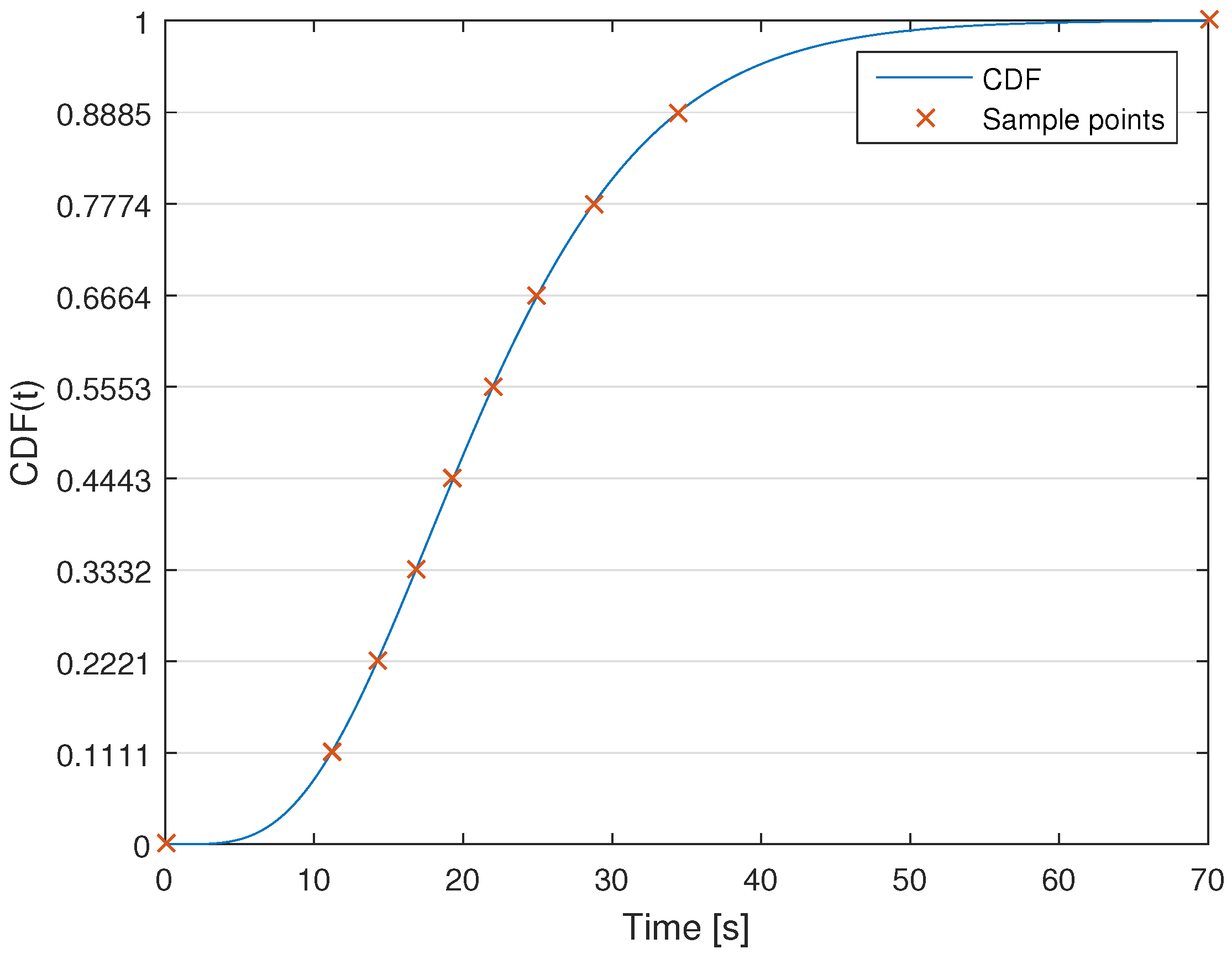
The number of calculations to be performed is too large for a single system; for this reason, an HTCondor cluster [28] composed of over 300 nodes has been used to calculate the optimal strategy when varying the values of and . The nodes work concurrently on different initial conditions to find the minimum cost by searching in the parameter space defined by the points , which can vary from (corresponding to the initial time and minimum power output) to . The time distribution of these points has been selected with the objective of maximising the variability of the interpolant when the changes in power output are more expected; that is, when the probability is higher. The points need to be adequately distributed, as well, so the choice for the values is the following: given a series of N points linearly distributed in the interval and given a CDF , the values are:
resulting in a distribution of , which tends to concentrate the values where the CDF changes more rapidly, which in turn corresponds to the instants when the probability is higher, as is visible in Figure 4.
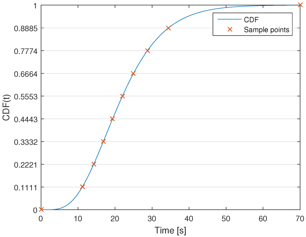
Figure 4.
Temporal distribution of 10 sample points of a piecewise cubic Hermite interpolating polynomial (PCHIP) interpolant superimposed on the CDF. The vertical position of the PCHIP points indicates the distribution in the region.
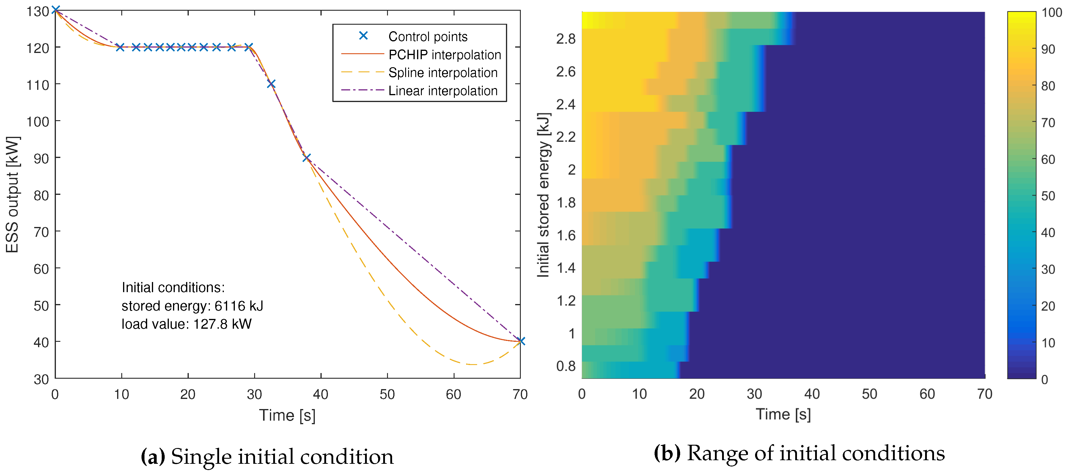
The output of the calculation is a matrix of parameters linked to an individual initial condition of the storage and value of the load. Given a particular scenario, the control system reads the optimal values calculated off-line and generates the optimal power output in real time via PCHIP interpolation. Figure 5a shows an example of the output of the calculation, as well as the PCHIP interpolation used as a reference for the control system. The parameters used in the minimisation (including discretisation and load ranges) are presented in Table 2. and indicate, respectively, the resolution used for the load power and the initial stored energy. A sample of the results of the calculations is shown in Figure 5b.
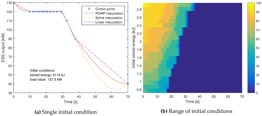
Figure 5.
Examples of control points calculated in the minimisation. (a) The control points calculated for a single pair of initial conditions. Three different interpolations are also shown (PCHIP, spline and linear). Notice how the spline interpolation does not maintain monotonicity. (b) A range of optimal control strategies calculated for 0.72 MJ < < 3.00 MJ and = 100 kW. The colour bar on the right shows the power output of the storage expressed in kW.

Table 2.
Parameters of the numerical minimisation.
4.2. Distribution of Lift Durations
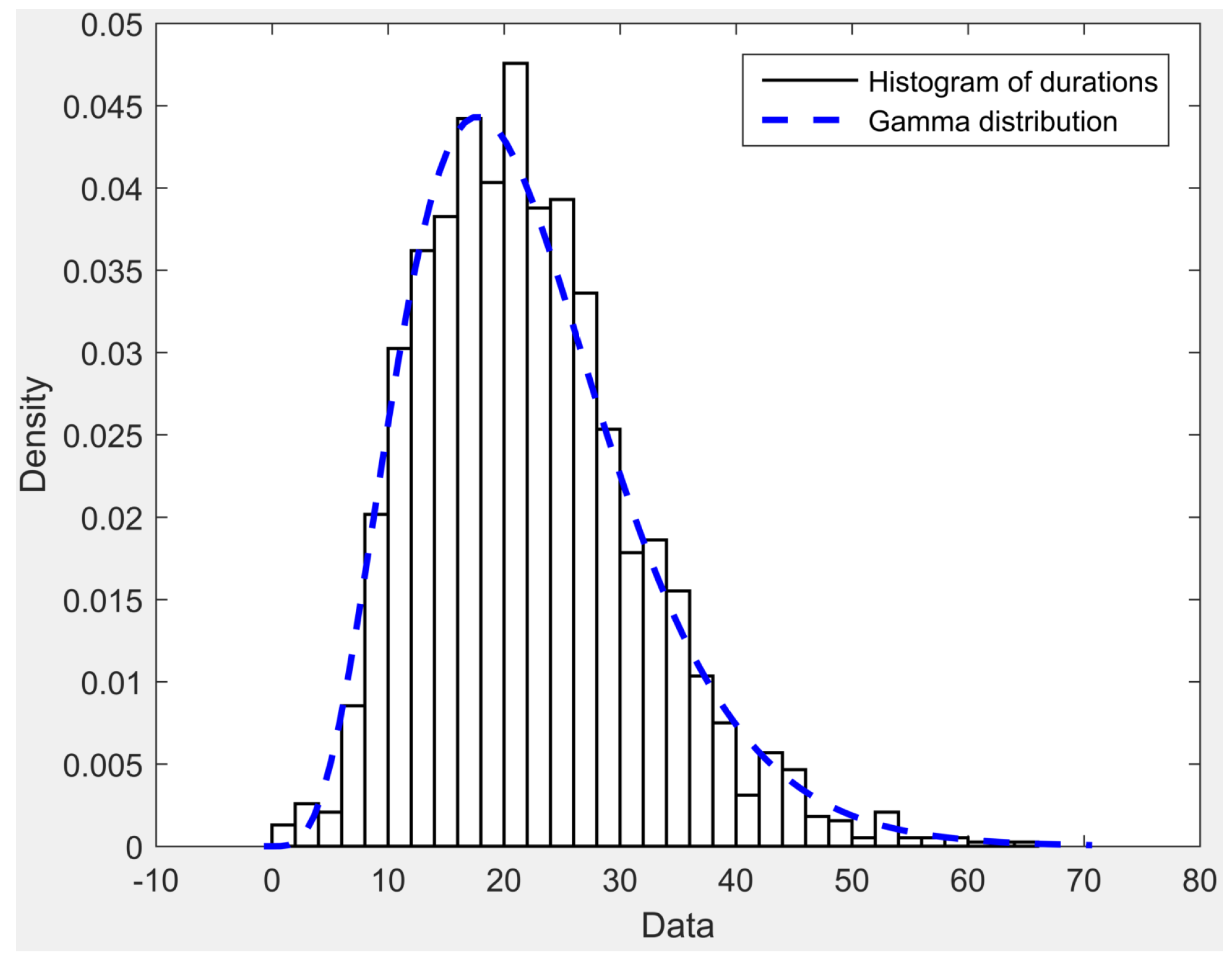
Measurements of the activity of an RTG crane were recorded at the Port of Felixstowe, including the duration of container lifts measured as the interval between the start of a lift (i.e., the hoist motor speed becomes positive) and its end when reaching zero speed. The data were collected for a period of six days, after which they were analysed and fit to a Gamma distribution, which has been chosen because it results in the best fit to the data and is defined by the constants α and β. The probability density of a Gammadistribution L is described by the following equation:
where is the Gamma function evaluated at α, and it is a constant:
The actual random variable t has a realistic upper limit T, as the duration of the load is limited in time, so the distribution used in the calculation has been truncated at . The parameters α and β have been found by minimising the squared error and are presented in Table 3. Figure 6 shows the histogram of lift durations superimposed on the Gamma distribution.

Table 3.
Parameters of the Gamma distribution that fit the lift duration data.
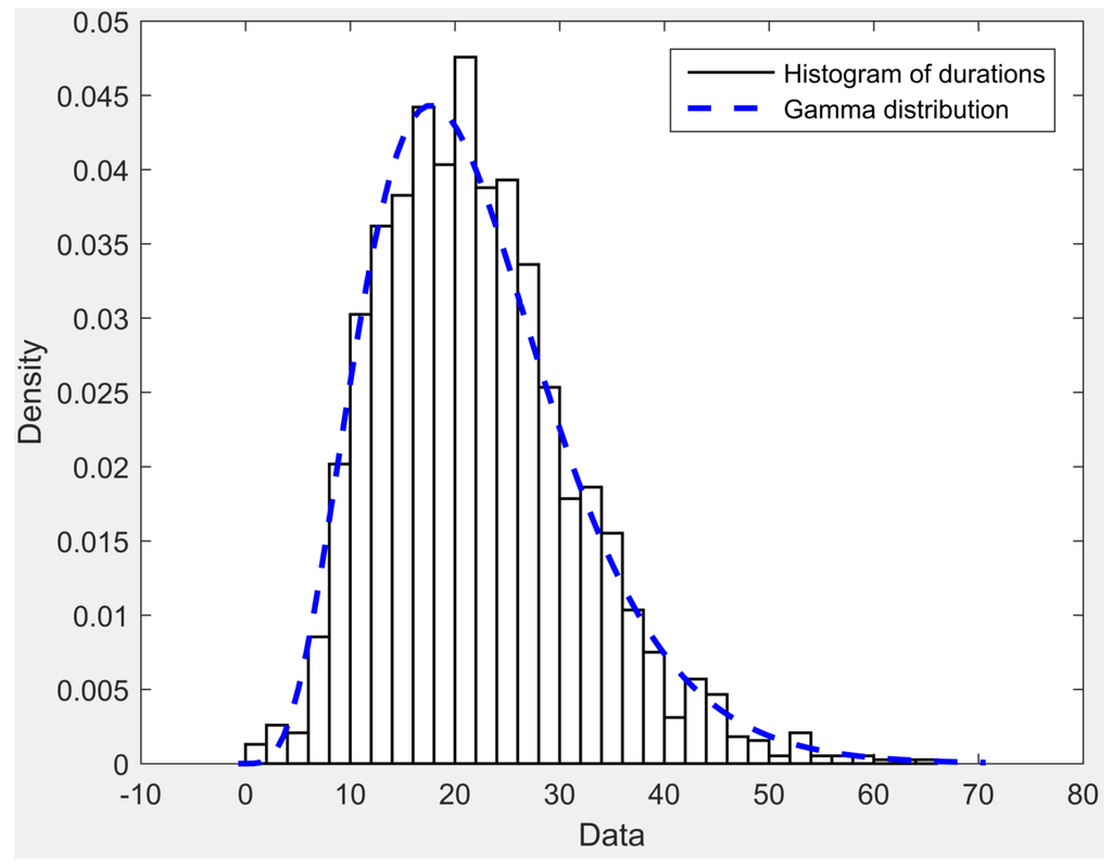
Figure 6.
Histogram of the lift durations superimposed on the Gamma distribution that fits the data.
The CDF can be easily pre-calculated off-line for each instant by integration or by using the following equation:
where is the lower incomplete gamma function and equal to:
4.3. Model of the RTG Crane
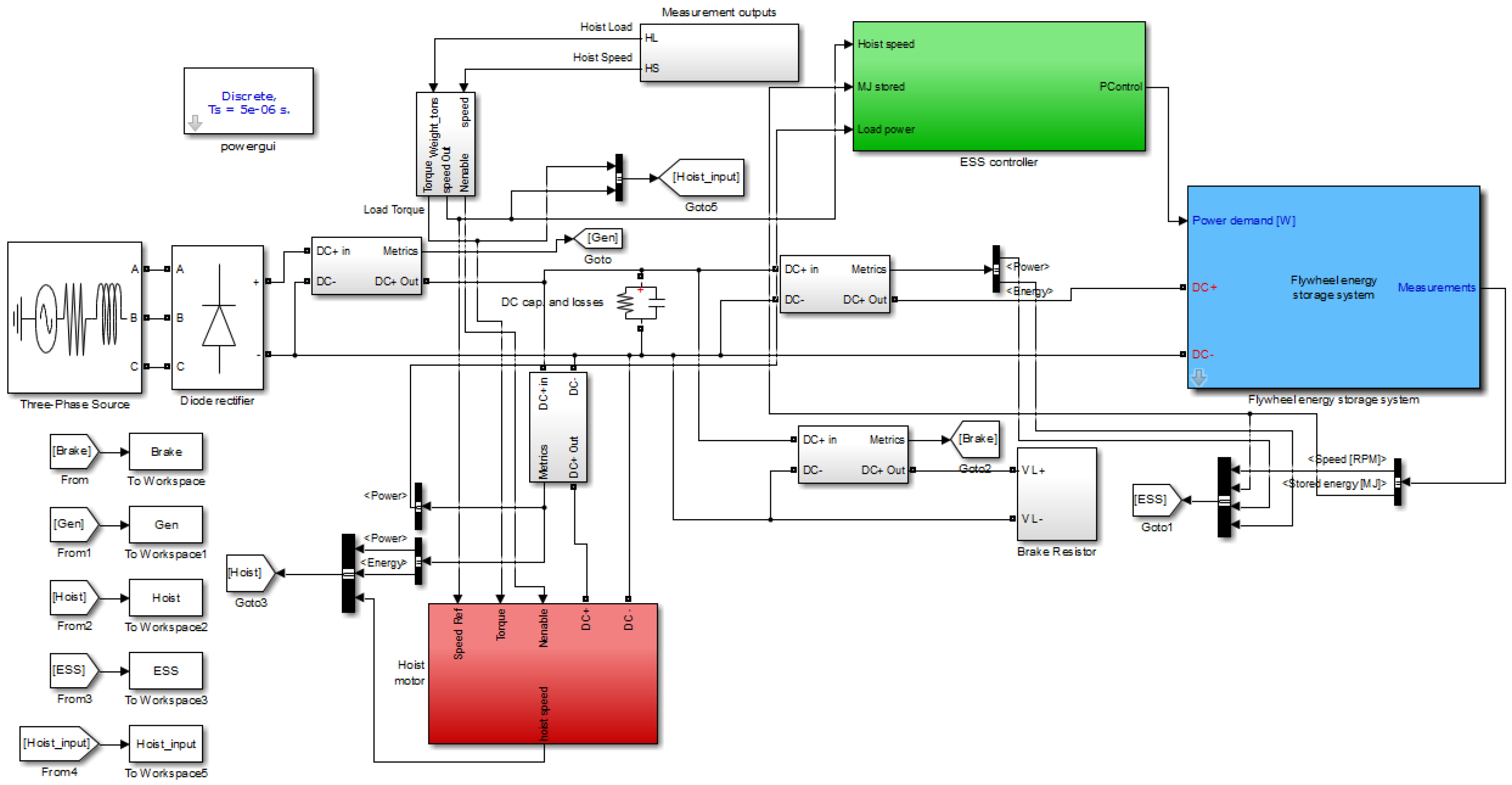
The main electrical and mechanical components of an RTG crane have been modelled in MATLAB/Simulink using the SimPowerSystems toolbox. This model was originally developed to study the operations of RTG cranes at the Port of Felixstowe [29,30], but it has been extended to be used to test the PMS by adding a model of an FESS connected to the DC bus of the crane, as is visible in Figure 7. The model is composed of three main elements: a primary source, the hoist motor and the FESS.
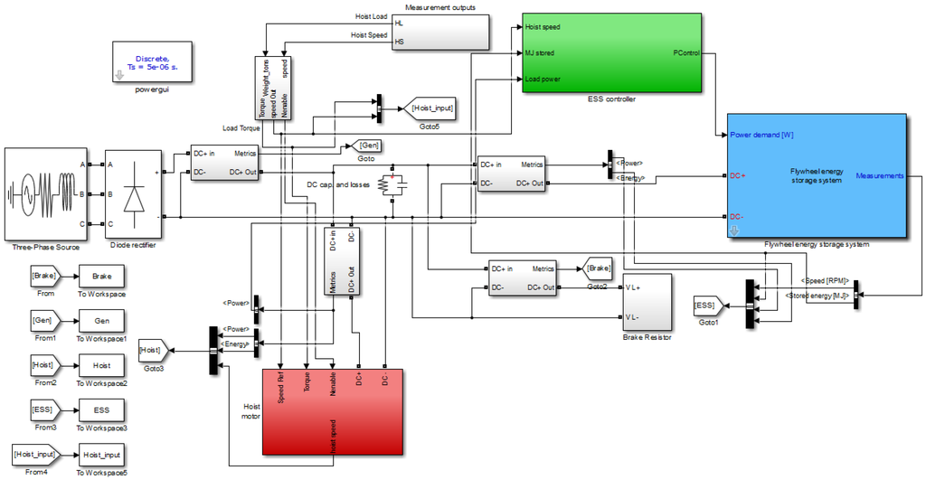
Figure 7.
Simulink model of the RTG crane used for the simulations.
4.3.1. Primary Source
In the model, the primary source is an ideal three-phase source connected directly to a diode rectifier, which powers the DC bus. Measurements are taken on the three-phase side to measure the energy consumed by the crane. The benefits of the storage and its control strategy will be assessed by analysing the energy consumed by the primary source. A good control strategy will need, as a primary objective, to reduce the energy consumption and also limit the peak power demand.
4.3.2. The Hoist Motor
An induction motor rated at 200 kW is connected to the DC bus. It is powered by a drive, which controls the motor speed following a reference value extracted directly from measurements taken at the Port of Felixstowe. It draws power from the DC bus when raising a container and then generates power back into the bus when lowering. The regenerated energy is collected by the energy storage until it reaches maximum capacity, then the remaining energy is dissipated into brake resistors.
4.3.3. The Flywheel Energy Storage System
The storage system model has been developed to test the PMS proposed in this paper. The model, shown in Figure 8, is based on a prototype powered by a 150-kW, 12/10 pole switched reluctance motor whose model and low-level control system has been provided by the manufacturer Nidec SR Drives (Harrogate, UK); the motor is coupled to a flywheel whose inertia has been measured to be 3.0447 kg/m. The maximum rotational speed is 15,000 RPM, and the minimum speed is set to 5000 RPM; the total capacity is then 3.34 MJ, which equates to 0.927 kWh. The low-level control system is designed to provide any output power up to the rated value of ±150 kW with a maximum delay of 0.6 ms; this is fast compared to the dynamics of the hoist motor, meaning that the low-level control is fully transparent to the PMS.

Figure 8.
Simulink model of the flywheel energy storage system.
4.4. Test Cycle
The activity of a diesel-powered RTG crane was measured for the duration of one hour during a typical day. Among the recorded signals were the speed of the hoist motor and the container weight, which have been used in the RTG model to simulate the operation of the crane. The characteristics of this hour of crane operations are presented in Table 4 and represent the typical activity of an RTG crane, consisting mainly of the combination of four basic hoist movements and their accompanied energy flows:
- The empty headblock is lowered over a container: a small amount of energy is regenerated;
- The load is hoisted to a height decided by the crane operator: a large amount of energy is consumed;
- The load is lowered in place: a large amount of energy is regenerated;
- The headblock is hoisted back into the starting position: a small amount of energy is consumed.

Table 4.
Characteristics of the test cycle.
During the simulation, in the first and third movements, the energy is either dissipated as heat or, when a storage system is present, is stored in the ESS. The crane then uses the stored energy, if available, in the second and fourth movements according to the control system implemented.
The simulation was repeated with different ESS scenarios as follows:
- No ESS: In this scenario, no storage is installed, and all of the recovered energy is dissipated through the brake resistors;
- Constant power: The ESS uses a set-point control strategy where the ESS output is limited to a value that is the average load power, i.e., ;
- Proposed PMS: An ESS with the optimal control strategy proposed in this paper;
- Infinite capacity: An ideal ESS with unlimited energy capacity and set to absorb or generate energy with a power limit of 150 kW with no time limitations, similarly to the second scenario, but with no capacity constraints and with the highest power limit.
In all of the scenarios, the ESS is set to charge only using recovered energy from lowered containers (no trickle charge, as the storage is never charged directly by the primary source). Scenario 2 is a simple and robust control strategy, which has already been implemented [14] and replicates most power-sharing control strategies. Scenario 4 extends 2 by increasing the power upper limit to the maximum rating of the storage and also increases the capacity to an unlimited value, in order to represent a simple and ideal scenario.
4.5. Results of the Simulation and Analysis
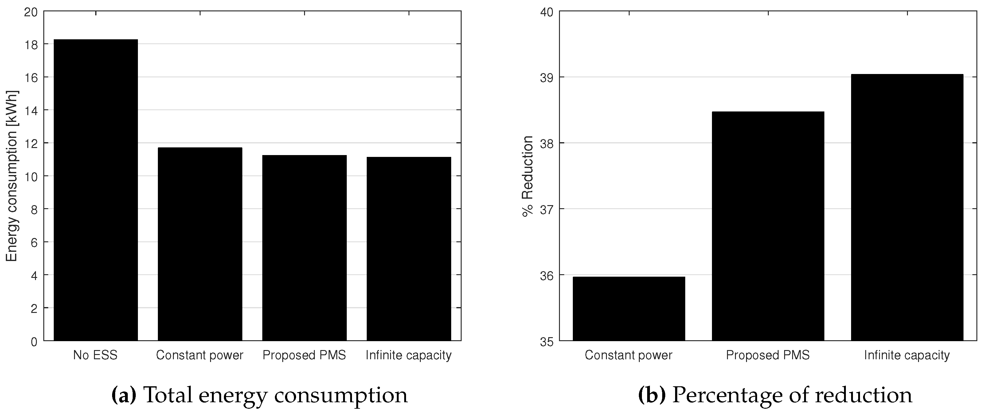
The simulations produced different results depending on the scenario, with the presence of the storage resulting in reduced energy consumption, as shown in Figure 9. With no storage, the crane wasted a significant amount of energy in the brake resistors, as all of the potential energy recovered from lowering the container is not being stored. The addition of the storage greatly increases the efficiency of the system, as it enables the reutilisation of regenerated energy, and the benefits are evident in Figure 9a. The three different control strategies used in Scenarios 2, 3 and 4 produced significantly different results. In particular, the set-point control with constant power output reduced the energy consumption by 35.9%; in this particular test cycle, this is the best achievable outcome for this kind of control, as the power limit is set by knowing in advance the average power consumption. The ideal energy storage with infinite capacity reached a reduction of 39.0%, and this is the upper bound for a system with a power rating of 150 kW. The proposed PMS is only slightly worse than the ideal case with a 38.47% reduction (see Figure 9b).
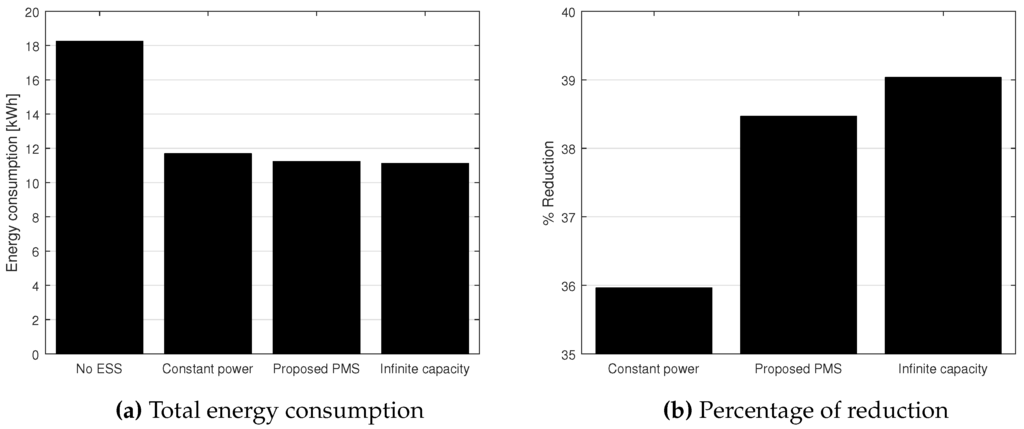
Figure 9.
Results from the test cycle. (a) The total energy from the primary source for the four scenarios; (b) the percentage of reduction of energy consumption for the three storage scenarios with respect to the first scenario.
The minimisation criteria used in the PMS also originate a significant reduction in peak power demand, since the quadratic cost function penalises large quantities of primary supply power. This is reflected in Table 5, where the percentage of time that the primary source is outputting more than 150 and 200 kW is shown. The proposed PMS has promising results with respect to the other control systems, including the scenario with infinite storage, as it effectively reduces the stress on the primary source during peak demand. The proposed PMS limits the peak better than the infinite capacity scenario due to the fact that the latter uses all of the recovered energy at the beginning of the lift, causing the storage to be depleted prematurely and forcing the generator to take over for the rest of the duration of the lift. The reduction in peak power consumption achieved by the proposed PMS reduces the stress on the primary source and allows for the downsizing of the diesel generator or the substation feeding the hybrid cranes; this could potentially be an opportunity for further reductions in costs for terminal operators (in addition to the energy cost savings).

Table 5.
Percentage of time that the primary source power output is over 150 and 200 kW. PMS, power management strategy.
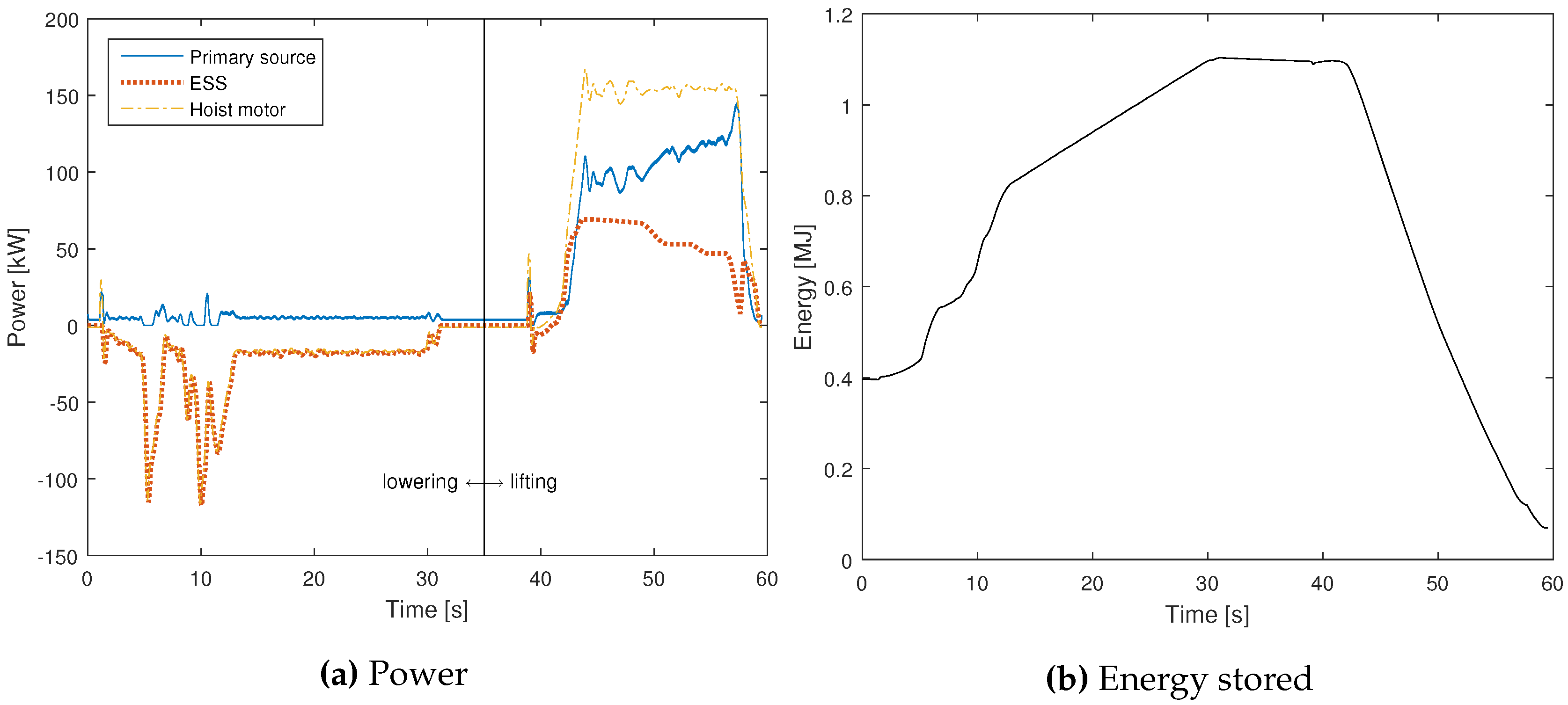
An example of the behaviour of the energy storage is visible in Figure 10, which shows a slice of the simulation when the hoist motor performs a lowering and a lifting. In the example, the energy storage starts with around 0.4 MJ of stored energy (Figure 10b), and it recovers the regenerated power (shown in Figure 10a as the negative power). At the end of the lowering, the ESS reaches almost 1.1 MJ of stored energy (relatively low, as it was only lowering an empty headblock), with the flywheel spinning at around 9500 RPM. The stored energy is used in the second part, during the lift of a container, reducing the power demand on the primary source. At the end of the cycle, the ESS ends with very little remaining energy.
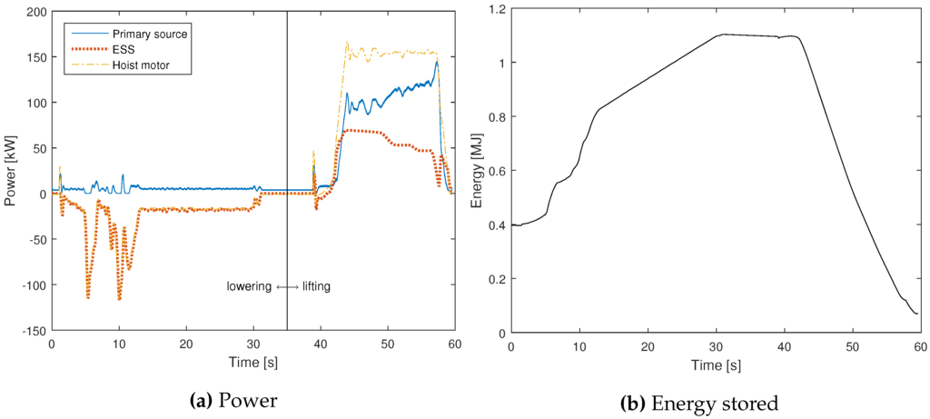
Figure 10.
Example extracted from the simulation. (a) The power flows of the three main elements in the model; when lowering, the ESS power is equal to the hoist power; (b) the profile of the energy stored in the ESS.
The intensity of the activity of the hybrid crane has an impact on the energy savings: low utilisation causes lower savings due to the larger times between lifts (and consequent high standing losses of the storage). Nevertheless, the proposed PMS optimisation process is limited to the single lift and is not dependent on their frequency, and it is only sensible to variations in the distribution of lift durations. Major changes in the container terminal operations could cause, for example, a reduction or an increase in average stack heights, leading to shorter or longer lift durations. This will need to be addressed by recalculating the optimal strategy with the new distribution parameters.
5. Conclusions
A power management strategy has been developed that minimises the energy costs associated with systems subjected to stochastic loads with a random duration. An optimal control problem has been established where the cost function takes into account the variability of the load, penalising the energy cost depending on the probability that a certain condition occurs. After accurately reducing the search space, an HTCondor cluster has been used to perform the numerical calculations aimed at obtaining the global minimum. A set of control strategies has been calculated for a range of possible initial conditions, and the resolution has been increased by interpolating the results.
The calculated PMS has been implemented in a MATLAB/Simulink model of a rubber tyre gantry crane equipped with a flywheel energy storage system; the results of the simulation show that the proposed power management strategy performs better than existing control strategies and very close to the ideal case. In particular, the results show that energy storage with optimal control reduces energy consumption and peak power demand, resulting in an efficient utilisation of the limited capacity of the storage. As the simulations show, using the proposed strategy for energy storage could reduce the energy consumption in container ports by a significant amount, as RTG cranes account for a large portion of the port’s total demand. The added benefit of peak power reduction could potentially minimise the maintenance costs for diesel generators and/or reduce the stress on the electrical infrastructure of the port.
Acknowledgments
This work was supported by Climate-KIC (Knowledge and Innovation Community) through the project Delivering sustainable energy solutions for ports (SUSPORTS). The authors are grateful for the help given by the Port of Felixstowe in collecting data on RTG cranes and providing knowledge about the crane operations.
Author Contributions
All of the authors contributed to the editing and improvement of the manuscript. Stefano Pietrosanti developed the control strategy, the model and analysed the results.William Holderbaum and Victor M. Becerra provided the methodology, contributed to the analysis of results and supervised all of the processes.
Conflicts of Interest
The authors declare no conflict of interest.
Abbreviations
The following abbreviations are used in this manuscript:
| PMS | Power Management Strategy |
| RTG | Rubber tyre gantry, a type of container crane |
| ESS | Energy storage system |
| FESS | Flywheel energy storage system |
| CDF | Cumulative distribution function |
| PCHIP | Piecewise cubic Hermite interpolating polynomial |
| SR | Switched reluctance (electric motor) |
Nomenclature
Power demand from the load | |
Power from the primary source (e.g., diesel generator) | |
Power from the storage system | |
Power rating of the storage system | |
Total cost associated with the energy production | |
Cost function associated with energy production | |
Constant power demand of the load | |
Energy stored in the storage system at time t | |
Energy capacity of the storage system | |
Constants defining the dynamic properties of the storage system | |
Probability that an event occurs at time t when defined by a distribution L | |
Cumulative distribution function associated with the distribution L | |
constant parameters that define a Gamma distribution |
Appendix A
Theorem 1.
Given a distribution L whose known probability density function is , with , and whose CDF is , and given continuous functions and that satisfy the following:
then the following is true:
References
- Ter-Gazarian, A.G. Energy Storage for Power Systems; The Institution of Engineering and Technology (IET): Stevenage, UK, 2011. [Google Scholar]
- Zeng, Y.; Cai, Y.; Huang, G.; Dai, J. A review on optimization modeling of energy systems planning and GHG emission mitigation under uncertainty. Energies 2011, 4, 1624–1656. [Google Scholar] [CrossRef]
- Chen, H.; Cong, T.N.; Yang, W.; Tan, C.; Li, Y.; Ding, Y. Progress in electrical energy storage system: A critical review. Prog. Nat. Sci. 2009, 19, 291–312. [Google Scholar] [CrossRef]
- Rowe, M.; Yunusov, T.; Haben, S.; Singleton, C.; Holderbaum, W.; Potter, B. A peak reduction scheduling algorithm for storage devices on the low voltage network. IEEE Trans. Smart Grid 2014, 5, 2115–2124. [Google Scholar] [CrossRef]
- Haben, S.; Ward, J.; Vukadinovic Greetham, D.; Singleton, C.; Grindrod, P. A new error measure for forecasts of household-level, high resolution electrical energy consumption. Int. J. Forecast. 2014, 30, 246–256. [Google Scholar] [CrossRef]
- Rowe, M.; Yunusov, T.; Haben, S.; Holderbaum, W.; Potter, B. The real-time optimisation of DNO owned storage devices on the LV network for peak reduction. Energies 2014, 7, 3537–3560. [Google Scholar] [CrossRef]
- Zhang, Y.; Gatsis, N.; Giannakis, G.B. Robust energy management for microgrids with high-penetration renewables. IEEE Trans. Sustain. Energy 2013, 4, 944–953. [Google Scholar] [CrossRef]
- Liang, H.; Zhuang, W. Stochastic modeling and optimization in a microgrid: A survey. Energies 2014, 7, 2027–2050. [Google Scholar] [CrossRef]
- Brahma, A.; Guezennec, Y.; Rizzoni, G. Optimal energy management in series hybrid electric vehicles. In Proceedings of the 2000 American Control Conference, Chicago, IL, USA, 28–30 June 2000; Volume 1, pp. 60–64.
- Lin, W.S.; Zheng, C.H. Energy management of a fuel cell/ultracapacitor hybrid power system using an adaptive optimal-control method. J. Power Sources 2011, 196, 3280–3289. [Google Scholar] [CrossRef]
- Romaus, C. Optimal energy management for a hybrid energy storage system for electric vehicles based on stochastic dynamic programming. In Proceedings of the 2010 IEEE Vehicle Power and Propulsion Conference (VPPC), Lille, France, 1–3 September 2010.
- Flynn, M.; Mcmullen, P.; Solis, O. Saving energy using flywheels. IEEE Ind. Appl. Mag. 2008, 14, 69–76. [Google Scholar] [CrossRef]
- Baalbergen, F.; Bauer, P.; Ferreira, J. Energy storage and power management for typical 4Q-load. IEEE Trans. Ind. Electron. 2009, 56, 1485–1498. [Google Scholar] [CrossRef]
- Iannuzzi, D.; Piegari, L.; Tricoli, P. Use of supercapacitors for energy saving in overhead travelling crane drives. In Proceedings of the 2009 International Conference on Clean Electrical Power, Capri, Italy, 9–11 June 2009; pp. 562–568.
- Xu, J.; Yang, J.; Gao, J. An integrated kinetic energy recovery system for peak power transfer in 3-DOF mobile crane robot. In Proceedings of the 2011 IEEE/SICE International Symposium on System Integration (SII), Kyoto, Japan, 20–22 December 2011; pp. 330–335.
- Kim, S.-M.; Sul, S.-K. Control of rubber tyred gantry crane with energy storage based on supercapacitor bank. IEEE Trans. Power Electron. 2006, 21, 262–268. [Google Scholar] [CrossRef]
- Hellendoorn, H.; Mulder, S.; de Schutter, B. Hybrid control of container cranes. In Proceedings of the 18th IFAC World Congress, Milan, Italy, 28 August–2 September 2011; Volume 19, pp. 9697–9702.
- Hedlund, M.; Lundin, J.; de Santiago, J.; Abrahamsson, J.; Bernhoff, H. Flywheel energy storage for automotive applications. Energies 2015, 8, 10636–10663. [Google Scholar] [CrossRef]
- Levron, Y.; Shmilovitz, D. Optimal power management in fueled systems with finite storage capacity. IEEE Trans. Circuits Syst. I Regul. Pap. 2010, 57, 2221–2231. [Google Scholar] [CrossRef]
- Levron, Y.; Shmilovitz, D. Power systems’ optimal peak-shaving applying secondary storage. Electr. Power Syst. Res. 2012, 89, 80–84. [Google Scholar] [CrossRef]
- Singer, S. Canonical approach to energy processing network synthesis. IEEE Trans. Circuits Syst. 1986, 33, 767–774. [Google Scholar] [CrossRef]
- Montgomery, D.; Runger, G. Applied Statistics and Probability for Engineers; John Wiley & Sons: Hoboken, NJ, USA, 2010. [Google Scholar]
- Driessen, B.J. On-off minimum-time control with limited fuel usage: Near global optima via linear programming. Optim. Control Appl. Methods 2006, 27, 161–168. [Google Scholar] [CrossRef]
- Singhose, W.; Singh, T.; Seering, W. On-off control with specified fuel usage. J. Dyn. Syst. Meas. Control 1999, 121, 206–212. [Google Scholar] [CrossRef]
- Kirk, D.E. Optimal Control Theory: An Introduction; Courier Corporation: Mineola, NY, USA, 2004; p. 452. [Google Scholar]
- Fritsch, F.N.; Carlson, R.E. Monotone piecewise cubic interpolation. SIAM J. Numer. Anal. 1980, 17, 238–246. [Google Scholar] [CrossRef]
- Kahaner, D.; Moler, C.; Nash, S. Numerical Methods and Software; Prentice-Hall: Englewood Cliffs, NJ, USA, 1989; p. 495. [Google Scholar]
- Thain, D.; Tannenbaum, T.; Livny, M. Distributed computing in practice: The Condor experience. Concurr. Pract. Exp. 2005, 17, 323–356. [Google Scholar] [CrossRef]
- Knight, C.; Becerra, V.; Holderbaum, W.; Mayer, R. A consumption and emissions model of an RTG crane diesel generator. In Proceedings of the TSBE EngD Conference, TSBE Centre, Whiteknights, UK, 5 July 2011.
- Knight, C.; Becerra, V.; Holderbaum, W.; Mayer, R. Modelling and simulating the operation of RTG container cranes. In Proceedings of the 6th IET International Conference on Power Electronics, Machines and Drives (PEMD 2012), Bristol, UK, 27–29 March 2012; pp. F24–F24.
© 2016 by the authors; licensee MDPI, Basel, Switzerland. This article is an open access article distributed under the terms and conditions of the Creative Commons by Attribution (CC-BY) license (http://creativecommons.org/licenses/by/4.0/).

