Abstract
The wettability, microstructures, and bonding strength of infrared brazing Ti-15-3 and Ti50Ni50 shape memory alloy using 72Ag-28Cu (wt.%) and 68.8Ag-26.7Cu-4.5Ti (wt.%) filler metals have been investigated. Only Ticusil® active braze readily wets both Ti50Ni50 and Ti-15-3 substrates. Wetting of eutectic 72Ag-28Cu melt on Ti50Ni50 base metal is greatly ameliorated by adding 4.5 wt.% Ti into the alloy. The brazed Ti-15-3/BAg-8/Ti50Ni50 joint consists of Cu-Ti intermetallics in the Ag-rich matrix. The formation of interfacial Cu(Ti,V) and (CuxNi1−x)2Ti intermetallics next to Ti-15-3 and Ti50Ni50 substrates, respectively, is attributed to the wetting of both substrates. The brazed Ti-15-3/Ticusil®/Ti50Ni50 joint shows a vigorous reaction, which results in the formation of a large amount of Ti2Ni intermetallics in the joint. The maximum joint strengths using BAg-8 and Ticusil® filler metals are 197 MPa and 230 MPa, respectively.
1. Introduction
Ti50Ni50 shape memory alloy (SMA) possesses excellent pseudoelasticity and shape memory effect [,]. Experimental results also demonstrate that Ti50Ni50 SMA is characterized by a very good biocompatibility [,,]. Thus, it has led to extensive applications in biomedicine and engineering [,,]. Titanium alloys have good specific strength as well as corrosion resistance, so they are widely applied in medical and aerospace applications. Ti-15-3 is a type of β-Ti alloy that has excellent forming characteristics at low temperatures []. Its chemical composition in wt.% is 3 Al, 3 Cr, 3 Sn, 15 V, and balance Ti. The strength of heat-treated Ti-15-3 primarily results from dispersed α-Ti precipitates in a β-Ti matrix [].
Advancements in joining processes are crucial in many engineering alloy applications. Oliveira et al. updates recent advancements in joining Ti50Ni50 SMA []. Many studies on joining Ti50Ni50 and its effects on the joint performance have been evaluated [,,,,]. Additionally, dissimilar joining of Ti50Ni50 SMA is a complex issue relating to the joined base metal because of brittle intermetallics formation in the joint []. Joining Ti50Ni50 to Ti-15-3 alloy is of great interest because it provides excellent combined functional characteristics owned by Ti50Ni50 and the mechanical/corrosion features of Ti-15-3 [].
It is well known that brazing is more appropriate than welding for bonding dissimilar alloys. Infrared brazing is more suitable than furnace brazing for evaluating the evolution of joint microstructures because of its heating rate as high as 50 °C/s [,]. The base metal is less affected by the thermal history of infrared brazing, so it is applied in the experiment. It is important to use an appropriate filler foil for brazing Ti50Ni50 SMA and Ti-15-3 alloy. The wettability of braze melt on the base metal and reaction(s) at the interface between the braze melt and base metal must both be considered in filler metal selection. According to previous studies, many titanium alloys are well brazed with Ag-based braze alloys [,,,]. However, the Ag-Cu eutectic melt cannot effectively wet the Ti50Ni50 substrate unless the active ingredient, Ti, is alloyed into the braze []. Ti50Ni50 SMA and 316 stainless steel have been infrared brazed using the Ticusil® (68Ag-26.7Cu-4.5Ti, wt.%) braze alloy, and the highest shear strength of such joints is 237 MPa for specimens joined below 950 °C [].
In this study, BAg-8 (72Ag-28Cu, wt.%) and Ticusil® foils were selected as the brazing fillers. The eutectic of the BAg-8 filler is 780 °C, and the liquidus of the Ticusil® filler is 850 °C. This research was focused on wetting and infrared brazing of Ti50Ni50 and Ti-15-3 alloys. Microstructures, dynamic wetting behaviors of the two fillers, as well as bonding strengths of joints were examined.
2. Materials and Methods
Ti50Ni50 SMA was made by using a vacuum arc remelter with pure titanium and nickel pellets. Pure titanium and nickel granules were degreased with 1HF-5HNO3-64H2O (in cm3) and 2HCl-25HNO3-75CH3COOOH (in cm3) solutions before being vacuum arc remelted. During the melting, the master alloy was melted at least six times with a pure titanium block as the getter, and its weight loss was below 0.1%. The Ti50Ni50 ingot was hot-rolled and homogenized at 900 °C to obtain plates of 3 mm thickness. A Ti-15-3 plate with a thickness of 3 mm was used as the substrate. BAg-8 and Ticusil® fillers with 50 μm in thickness were obtained from Morgan Advanced Materials Inc., Berkshire, UK.
Figure 1a displays the experimental installation of the wetting angle test, and it contains infrared lamps, a sample holder, and a CCD recording system []. The infrared furnace (SINKO-RIKO RHL-816C, ULVAC, Tokyo, Japan) under a vacuum of 5 × 10⁻⁸ bar was used in the wetting angle and brazing experiments. Infrared furnace heating rate was fixed at 10 °C/s during the test. The braze alloy prepared by a vacuum arc remelting furnace with a near spherical shape, weighing 0.15 g was applied in the wetting angle experiment. Figure 1b shows the thermocouple location of the specimen holder, and the thermocouple was in contact with the specimen holder [].
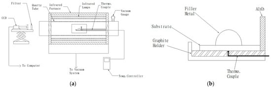
Figure 1.
(a) Experimental installation of the wetting angle test and (b) thermocouple location of the specimen holder in part (a).
All joined surfaces were ground sequentially with SiC papers of 240, 400, 600, 800, and 1200 grit with a scratch depth of approximately 15 μm []. Next, they were cleaned in an ultrasonic bath prior to brazing. The power of the ultrasonic bath was 150 W with a fixed frequency of 43 kHz. The brazing foil was placed in between the Ti50Ni50 and Ti-15-3 base metals. The specimen was enclosed by a graphite fixture with a thermocouple inserted into the lower graphite plate (Figure 1b). Preheating temperatures of BAg-8 and Ticusil® brazes were 700 and 800 °C for 300 s, respectively. Table 1 shows the wetting angle and shear test conditions applied in tests.

Table 1.
Wetting angle and shear test conditions applied in test.
Bonding strengths of joints were assessed with the symmetric double lap shear tests as described in previous reports [,,]. Figure 2 displays the shear test sample and applied forces in the shear test. The brazing filler foil, indicated by bold lines with the width of 3 mm, was placed in between the Ti50TNi50 and Ti-15-3 base metals. Shear tests of the infrared brazed joint were evaluated using a Shimadzu AG-10 universal testing machine (Shimadzu Corporation, Nakagyo-ku, Japan) and its crosshead speed was kept at 0.0167 mm/s. The cross-sections of the infrared brazed joint were inspected with a Nova Nano 450 field emission scanning electron microscope (FESEM, FEI Corp., Hillsboro, OR, USA). Operation voltage of 15 kV and 1 μm spot size were applied in the inspection.

Figure 2.
Illustration of the shear test sample and applied forces in shear test.
3. Results and Discussion
3.1. Dynamic Wetting Angle Test
Figure 3 illustrates the dynamic wetting behaviors of the BAg-8 and Ticusil® filler metals on Ti-15-3 substrate at various temperatures for 300 s. From Figure 3, one can find that the BAg-8 braze could not well wet the Ti-15-3 substrate at 800 °C, but the wettability was greatly increased by increasing the testing temperature to 850 °C, at which the wetting angle of 20° was readily reached after 60 s. On the other hand, the molten BAg-8 braze demonstrated poor wettability on a Ti50Ni50 substrate, even when the testing temperature was increased to 850 °C []. Figure 3 also shows the dynamic wetting angle behavior of the Ticusil® alloy on Ti-15-3 base metal at 900 and 950 °C. The molten Ticusil® braze effectively wetted the Ti-15-3 substrate, and the wettability was slightly improved by increasing the test temperature from 900 °C to 950 °C. The wetting angle approached zero after 70 s in both test conditions. Unlike the BAg-8 filler metal, the Ticusil® alloyed with 4.5 wt.% Ti active ingredient, which greatly ameliorates wetting on both Ti-15-3 and Ti50Ni50 substrates [].
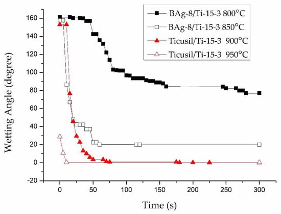
Figure 3.
Wetting angles of BAg-8 and Ticusil® on the Ti-15-3 substrate at different temperatures.
Figure 4 and Table 2 display FESEM backscattered electron images (BEIs) and chemical analysis results for the BAg-8 filler metal after wetting angle tests of the Ti-15-3 substrate at 800 and 850 °C for 300 s, respectively. In Figure 4a, the microstructures are primarily the Ag-Cu eutectic and two gray interfacial reaction layers. The darker layer 1 near the Ti-15-3 substrate, marked A, is Cu(Ti,V) intermetallics with minor white acicular Ag-rich phase, and the lighter layer 2 near the Ag-Cu eutectic phase, marked B, is Cu4Ti. The thickness of layer 1 is about 10 μm, and that of layer 2 is less than 5 μm. The interfacial reaction layers are greatly coarsened, and their compositions were changed by increasing the test temperature from 800 to 850 °C. In Figure 4b, two interfacial reaction layers can be seen. Layer 1 is mainly composed of Cu(Ti,V) intermetallic compound, marked C, mixed with a minor acicular Ag-rich phase. Layer 2 is composed of three phases: the white Ag-rich phase, marked D; the darker gray Cu4(Ti,V)3 intermetallics, marked E; and the lighter gray Cu4Ti intermetallics, marked F. The thicknesses of layer 1 and layer 2 are 25 μm and 120 μm, respectively. Based on the Ti-V phase diagram, β-Ti and V are completely soluable with each other at high temperature []. Therefore, the Cu-Ti interfacial reaction layers alloyed with a little V are presented as Cu(Ti,V) and Cu4(Ti,V)3 compounds. However, no interfacial reaction layer was observed from the Ti50Ni50 side []. Fine Ag-Cu eutectic dominates the entire cross-section. The lack of an interfacial reaction layer results in insufficient wetting of the BAg-8 melt on the Ti50Ni50 base metal, as described in the previous work [].

Figure 4.
Cross-sectional observations of FESEM BEIs of Ti-15-3 substrate after wetting test using BAg-8 filler metal at (a) 800 and (b) 850 °C for 300 s.
Table 2.
Chemical analyses in Figure 4.
Figure 5 and Table 3 present FESEM BEIs and chemical analysis results using the Ticusil® filler metal after wetting angle tests of Ti-15-3 base metal at 900 and 950 °C for 300 s, respectively, in which interfacial reaction layers between the braze and base metal are found. In Figure 5a, it can be seen that the Cu content in the braze melt reacted vigorously with Ti and formed a gray Ti-Cu-V reaction layer (marked G) next to the Ti-15-3 substrate. A very thick CuTi intermetallic layer (marked H) is also visible. In Figure 5b, the thickness of the CuTi reaction layer was decreased due to better fluidity of the braze melt at increased brazing temperature. Most of the molten melt overflowed out of the joint without reacting with the Ti-15-3 substrate.
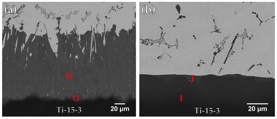
Figure 5.
Cross-sectional observations of FESEM BEIs of Ti-15-3 substrate after wetting angle test using Ticusil® filler metal at (a) 900 and (b) 950 °C for 300 s.
Table 3.
Chemical analyses in Figure 5.
3.2. Microstructures of Brazed Joints
3.2.1. Ti-15-3/BAg-8/Ti50Ni50 Joints
Figure 6a and Table 4 display the FESEM BEI and EDS chemical analysis results of a Ti-15-3/BAg-8/Ti50Ni50 specimen infrared brazed at 800 °C for 300 s. In Figure 6a, the infrared brazed joint mainly consists of Cu2Ti (marked L) and Ag-rich matrix (marked M). There are two interfacial reaction layers in the brazed joint. The interfacial layer between the braze alloy and Ti-15-3 is a Cu(Ti,V) compound, marked O, and that between the braze alloy and Ti50Ni50 is a Cu-Ni-Ti compound, marked K []. The Cu-Ni-Ti phase is expressed by (CuxNi1−x)2Ti, where x is between 0.23 and 0.75 at % []. It is obvious that the reaction between Cu and Ti plays an important role in brazing two Ti-based alloys. The interfacial Cu-Ni-Ti reaction layer results from the reaction between the Cu-Ti rich liquid and the Ti50Ni50 base metal.
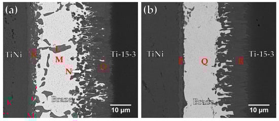
Figure 6.
FESEM BEI observations of Ti50Ni50/ BAg-8/ Ti-15-3 joints brazed at (a) 800 and (b) 850 °C for 300 s.
Table 4.
Chemical analyses in Figure 6.
Figure 6b displays FESEM BEI and EDS chemical analysis results of a Ti-15-3/BAg-8/Ti50Ni50 specimen infrared brazed at 850 °C for 300 s. Increasing the brazing temperature enhances the interfacial reaction among the braze melt and two substrates. Most of Cu in the molten braze readily react with Ti50Ni50 and Ti-15-3 substrates to form interfacial (CuxNi1−x)2Ti and Cu(Ti,V) reaction layers. According to Figure 6b, the Cu content in the molten BAg-8 braze was almost completely consumed. No Ag-Cu eutectic is visible in the figure, and only the white Ag-rich matrix, marked Q, remains in the center of the brazed joint. Meanwhile, the Cu2Ti phase disappears from the brazed joint at higher brazing temperature due to the enhanced interfacial reactions which consume Cu in the braze melt.
3.2.2. Ti-15-3/Ticusil®/Ti50Ni50 Joints
Figure 7a and Table 5 show FESEM BEI and chemical analysis results of a Ti-15-3/Ticusil®/Ti50Ni50 sample brazed at 900 °C for 300 s. The joint is mainly composed of CuNiTi (marked S) and CuTi2 (marked T) with a few Ag-rich particles (marked U). Two interfacial reaction layers were identified from the EDS analyses. A continuous CuTi2 interfacial layer (marked V and W) can be observed between the braze and Ti-15-3 substrate, and no reaction layer exists between the braze and Ti50Ni50 substrate. The CuNiTi phase belongs to the category of SMA, so it is regarded as beneficial to the shape memory effect of the brazed joint [].

Figure 7.
FESEM BEI observations of Ti50Ni50/ Ticusil®/ Ti-15-3 joints brazed at (a) 900 and (b) 950 °C for 300 s.
Table 5.
Chemical analyses in Figure 7.
Figure 7b displays FESEM BEI observation of Ti50Ni50/ Ticusil®/ Ti-15-3 joint brazing at 950 °C for 300 s. It is worth mentioning that most of the braze melt overflowed out of the joint at 950 °C. Increasing the brazing temperature to 950 °C, dissolution of Ni and Ti ingredients from Ti50Ni50 and Ti-15-3 substrates into the braze melt enhances and forms the Ti2Ni intermetallic compound in the central brazed zone. According to Figure 7b and Table 5, the central brazed region is filled with Ti2Ni intermetallic compound (marked X) and the Ti-rich phase (marked Y). Increasing the brazing temperature from 900 to 950 °C causes partial loss of Ticusil® braze melt from the joint and forms Ti2Ni intermetallic compound in the central region of the joint due to dissolution of two base metals into braze melt.
3.3. Shear Strengths of Brazed Joints
Table 6 displays the average shear strengths of joints fabricated under various brazing conditions. For the BAg-8 filler, shear strength of the joint is increased by increasing the brazing temperature because of the better wettability of the filler at higher temperature, as illustrated in Figure 3. For the Ticusil® filler, the shear strength of the brazed joints was also slightly higher for the joints brazed at higher temperature, although the Ticusil® filler has quite good wettability at both 900 °C and 950 °C. The best strength of the BAg-8 joints brazed at 850 °C for 300 s was 197 MPa while that of the Ticusil® joints brazed at 950 °C for 300 s was 230 MP. Cross-section BEIs and SEI (secondary electron image) fractographs of the fractured joints are shown in Figure 8 and Figure 9, respectively.
Table 6.
Average shear strengths of brazed joints.
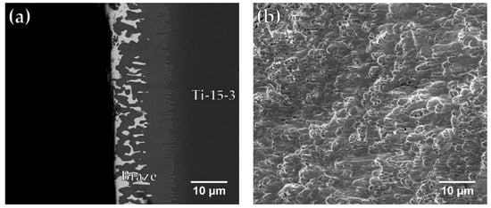
Figure 8.
FESEM (a) BEI cross section and (b) SEI fractograph of Ti-15-3/BAg-8/Ti50Ni50 joint brazed at 850 °C for 300 s after shear test.
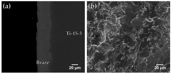
Figure 9.
FESEM (a) BEI cross section and (b) SEI fractograph of Ti-15-3/Ticusil®/Ti50Ni50 joint brazed at 950 °C for 300 s after shear test.
Figure 8a,b present an SEM BEI cross-section and a SEI fractograph of the fractured Ti-15-3/BAg-8/ Ti50Ni50 joint brazed at 850 °C for 300 s. The brazed specimen in Figure 8a fractured between the interfacial Cu(Ti,V) reaction layer and the Ag-rich matrix. The fractograph shown in Figure 8b presents quasi-cleavage fracture, and the morphology of fractured surface is mixed with ductile dimples and brittle facets. Figure 9a,b show an FESEM BEI cross-section and an SEI fractograph of the joint brazed at 950 °C for 300 s. The fracture location shown in Figure 9a is along the central brittle Ti2Ni intermetallic compound. The existence of central brittle intermetallics in the joint results in brittle cleavage fracture of the entire SEI fractograph as illustrated in Figure 9b.
Appropriate wetting ability of the braze melt on the base metal is one of the prerequisites to acquire a good joint. Alloying 4.5 wt.% Ti into the Ag-Cu eutectic, e.g., Ticusil® filler, improves its wetting on both substrates. However, alloying Ti into BAg-8 alloy increases both liquidus and brazing temperatures, which results in enhanced interfacial reaction and dissolution of both substrates. The amount of intermetallic phase in the brazed zone is significantly increased. For the Ti-15-3/Ticusil®/Ti50Ni50 joint, brazing at 950 °C for 300 s presents the best bonding strength of 230 MPa due to the presence of Ti2Ni matrix in the joint. A brittle, cleavage-dominated fractograph is observed after the shear test. In contrast, failure of interfacial reaction layers and ductile Ag-rich phase are found after the shear test of the BAg-8 brazed joint. Its average shear strength is slightly decreased to 197 MPa. The morphology of the fractured surface is mixed with ductile dimples and brittle facets.
Dissimilar infrared brazing of Ti-15-3 and Ti50Ni50 shape memory alloy using BAg-8 and Ticusil® foils have been evaluated. BAg-8 and Ticusil® fillers can effectively braze Ti50Ni50 shape memory alloy and Ti-15-3. The dissimilar infrared brazed joints show moderate average shear strengths of between 172 and 230 MPa. Dissimilar infrared brazing is faster than the traditional one. Additionally, very limited distortion of the joint was observed. It demonstrates the potential for application, e.g., the bimetal product with complex geometry which is not suitable for the cladding process.
4. Conclusions
Dissimilar infrared brazing of Ti50Ni50 SMA and Ti-15-3 β-Ti alloy with BAg-8 and Ticusil® foils have been investigated. Important conclusions are listed below.
- BAg-8 and Ticusil® brazing foils wet the Ti-15-3 substrate. The wettability of Ag-Cu eutectic is greatly ameliorated by alloying with 4.5 wt.% Ti.
- A Ti-15-3/BAg-8/Ti50Ni50 joint brazed at 800 °C for 300 s consists of Cu2Ti intermetallics in the Ag-rich matrix, and only the Ag-rich matrix remains in a joint infrared brazed at 850 °C for 300 s. An interfacial Cu(Ti,V) reaction layer next to Ti-15-3 and interfacial (CuxNi1−x)2Ti phase next to the Ti50Ni50 are attributed to the reactive wetting of both substrates.
- A Ti-15-3/Ticusil®/Ti50Ni50 joint brazed at 900 °C for 300 s consists of CuNiTi and CuTi2. A CuTi2 interfacial layer is next to the Ti-15-3 substrate. For the sample, brazing at 950 °C causes all Ag-rich melt to overflow out of the specimen, leaving the Ti2Ni matrix and Ti-rich particles in the joint.
- The best joint strengths using BAg-8 foil and Ticusil® are 197 and 230 MPa, respectively. For the BAg-8 joint, cracks propagate at the location between the interfacial Cu(Ti,V) and the Ag-rich phase. In a Ticusil® brazed joint, cracks are initiated and propagate along the central Ti2Ni intermetallic compound in the brazed zone.
- The dissimilar infrared brazed joints show moderate average shear strengths of between 172 and 230 MPa. It is a much faster process than that of the traditional furnace brazing, and very limited distortion of the joint is observed. It shows potential for future application in industry.
Author Contributions
Conceptualization, C.L., R.-K.S. and S.-K.W.; data curation, C.L. and T.-E.Y.; formal analysis, C.L.; funding acquisition, S.-K.W.; investigation, C.L., R.-K.S. and T.-E.Y.; methodology, C.L., R.-K.S. and T.-E.Y.; project administration, S.-K.W.; resources, S.-K.W.; supervision, S.-K.W.; visualization, C.L.; writing—original draft, C.L.
Funding
This research was funded by the Ministry of Science and Technology (MOST), Taiwan, with grant MOST 105-2221-E002-044-MY2 and MOST 107-2221-E-002-016-MY2.
Conflicts of Interest
There are no conflicts of interest.
References
- Otsuka, K.; Ren, X. Physical metallurgy of TiNi-based shape memory alloys. Prog. Mater. Sci. 2005, 50, 511–678. [Google Scholar] [CrossRef]
- Fili, P.; Lausmaa, J.; Musialek, J.; Mazanec, K. Structure and surface of TiNi human implants. Biomaterials 2001, 22, 2131–2138. [Google Scholar] [CrossRef]
- Firstov, G.S.; Vitchev, R.G.; Kumar, H.; Blanpain, B.; Van Humbeeck, J. Surface oxidation of NiTi shape memory alloy. Biomaterials 2002, 23, 4863–4871. [Google Scholar] [CrossRef]
- Chen, M.C.; Wu, S.K. Surface analyses and biocompatibility study of 500 °C oxidized Ni50Ti50 and Ni40Ti50Cu10 shape memory alloys. Surf. Coat. Technol. 2009, 203, 1715–1721. [Google Scholar] [CrossRef]
- Rocher, P.; El Medawar, L.; Hornez, J.C.; Traisnel, M.; Breme, J.; Hildebrand, H.F. Biocorrosion and cytocompatibility assessment of NiTi shape memory alloys. Scripta Mater. 2004, 50, 255–260. [Google Scholar] [CrossRef]
- Yoneyama, T.; Miyazaki, S. Shape Memory Alloys for Biomedical Applications; Woodhead Publishing: Cambridge, UK, 2008. [Google Scholar]
- Lecce, L.; Concilio, A. Shape Memory Alloy Engineering: For Aerospace, Structural and Biomedical Applications; Butterworth-Heinemann: Oxford, UK, 2014. [Google Scholar]
- Wang, L.; Zhang, L.C. Development and Application of Biomedical Titanium Alloys; Bentham Science Publishers: Sharjah, UAE, 2018. [Google Scholar]
- Welsch, G.; Boyer, R.; Collings, E.W. Materials Properties Handbook: Titanium Alloys; ASM International: Materials Park, OH, USA, 1993. [Google Scholar]
- Oliveira, J.P.; Miranda, R.M.; Braz Fernandes, F.M. Welding and joining of NiTi shape memory alloys: A review. Prog. Mater. Sci. 2017, 88, 412–466. [Google Scholar] [CrossRef]
- Olson, D.L.; Siewert, T.A.; Liu, S.; Edwards, G.R. ASM Handbook Volume 6: Welding, Brazing, and Soldering; ASM International: Materials Park, OH, USA, 1993. [Google Scholar]
- Li, H.M.; Sun, D.Q.; Cai, X.L.; Dong, P.; Wang, W.Q. Laser welding of TiNi shape memory alloy and stainless steel using Ni interlayer. Mater. Des. 2012, 39, 285–293. [Google Scholar] [CrossRef]
- Qiu, X.M.; Li, M.G.; Sun, D.Q.; Liu, W.H. Study on brazing of TiNi shape memory alloy with stainless steels. J. Mater. Process. Technol. 2006, 176, 8–12. [Google Scholar] [CrossRef]
- van der Eijk, C.; Sallom, Z.K.; Akselsen, O.M. Microwave brazing of NiTi shape memory alloy with Ag-Ti and Ag-Cu-Ti alloys. Scr. Mater. 2008, 58, 779–781. [Google Scholar] [CrossRef]
- Mirshekari, G.R.; Saatchi, A.; Kermanpur, A.; Sadrnezhaad, S.K. Laser welding of NiTi shape memory alloy: Comparison of the similar and dissimilar joints to AISI 304 stainless steel. Opt. Laser Technol. 2013, 54, 151–158. [Google Scholar] [CrossRef]
- Lee, S.J.; Wu, S.K.; Lin, R.Y. Infrared joining of TiAl intermetallics using Ti-15Cu-15Ni foil—i. The microstructure morphologies of joint interfaces. Acta Mater. 1998, 46, 1283–1295. [Google Scholar] [CrossRef]
- Shiue, R.K.; Wu, S.K.; Chen, S.Y. Infrared brazing of TiAl intermetallic using Bag-8 braze alloy. Acta Mater. 2003, 51, 1991–2004. [Google Scholar] [CrossRef]
- Shiue, R.K.; Wu, S.K.; Chan, C.H. The interfacial reactions of infrared brazing Cu and Ti with two silver-based braze alloys. J. Alloys Compd. 2004, 372, 148–157. [Google Scholar] [CrossRef]
- Shiue, R.K.; Wu, S.K.; Shiue, J.Y. Infrared brazing of Ti-6Al-4V and 17-4 PH stainless steel with (Ni)/Cr barrier layer(s). Mater. Sci. Eng. A 2008, 488, 186–194. [Google Scholar] [CrossRef]
- Shiue, R.K.; Chen, C.P.; Wu, S.K. Infrared brazing of Ti50Ni50 shape memory alloy and 316L stainless steel with two sliver-based fillers. Metall. Mater. Trans. A 2015, 46, 2364–2371. [Google Scholar] [CrossRef]
- Shiue, R.-K.; Wu, S.-K.; Yang, S.-H.; Liu, C.-K. Infrared dissimilar joining of Ti50Ni50 and 316L stainless steel with copper barrier layer in between two silver-based fillers. Metals 2017, 7, 276. [Google Scholar] [CrossRef]
- Shiue, R.H.; Wu, S.K. Infrared brazing of Ti50Ni50 shape memory alloy using two Ag-Cu-Ti active braze alloys. Intermetallics 2006, 14, 630–638. [Google Scholar] [CrossRef]
- Shiue, R.K.; Wu, S.K.; Chan, C.H. Infrared brazing Cu and Ti using a 95Ag-5Al braze alloy. Metall. Mater. Trans. A 2004, 35, 3177–3186. [Google Scholar] [CrossRef]
- Sandpaper-Wikipedia. Available online: https://en.wikipedia.org/wiki/Sandpaper (accessed on 4 May 2019).
- ASM International. ASM Handbook; ASM International: Materials Park, OH, USA, 1992; Volume 3. [Google Scholar]
- Shiue, R.H.; Wu, S.K. Infrared brazing Ti50Ni50 and Ti-6Al-4V using the Bag-8 braze alloy. Mater. Trans. JIM 2005, 46, 2057–2066. [Google Scholar] [CrossRef]
- Gupta, K.P. Phase Diagrams of Ternary Nickel Alloys: Ternary Systems Containing Co-Ni-X, Mn-Ni-X, Mo-Ni-X, Nb-Ni-X, Ni-Ta-X, Ni-Ti-X and Ni-V-X; Indian Institute of Metals: Kolkata, India, 1990. [Google Scholar]
© 2019 by the authors. Licensee MDPI, Basel, Switzerland. This article is an open access article distributed under the terms and conditions of the Creative Commons Attribution (CC BY) license (http://creativecommons.org/licenses/by/4.0/).